JP6179297B2 - Acoustic transducer and microphone - Google Patents
Acoustic transducer and microphoneDownload PDFInfo
- Publication number
- JP6179297B2 JP6179297B2JP2013190303AJP2013190303AJP6179297B2JP 6179297 B2JP6179297 B2JP 6179297B2JP 2013190303 AJP2013190303 AJP 2013190303AJP 2013190303 AJP2013190303 AJP 2013190303AJP 6179297 B2JP6179297 B2JP 6179297B2
- Authority
- JP
- Japan
- Prior art keywords
- electrode plate
- acoustic
- acoustic transducer
- diaphragm
- gap
- Prior art date
- Legal status (The legal status is an assumption and is not a legal conclusion. Google has not performed a legal analysis and makes no representation as to the accuracy of the status listed.)
- Active
Links
- 239000000758substrateSubstances0.000claimsdescription71
- 230000035945sensitivityEffects0.000claimsdescription24
- 230000004888barrier functionEffects0.000claimsdescription17
- 239000010409thin filmSubstances0.000claimsdescription10
- 238000004519manufacturing processMethods0.000claimsdescription5
- 239000000463materialSubstances0.000claimsdescription4
- 230000000903blocking effectEffects0.000claims1
- WABPQHHGFIMREM-UHFFFAOYSA-Nlead(0)Chemical compound[Pb]WABPQHHGFIMREM-UHFFFAOYSA-N0.000description11
- 230000004048modificationEffects0.000description11
- 238000012986modificationMethods0.000description11
- 230000002093peripheral effectEffects0.000description9
- 238000012545processingMethods0.000description9
- 238000010586diagramMethods0.000description8
- 229910021420polycrystalline siliconInorganic materials0.000description8
- 229920005591polysiliconPolymers0.000description8
- 230000007423decreaseEffects0.000description7
- 239000010408filmSubstances0.000description6
- 230000001154acute effectEffects0.000description5
- 239000003990capacitorSubstances0.000description5
- 238000000034methodMethods0.000description5
- 230000001681protective effectEffects0.000description5
- 238000001514detection methodMethods0.000description4
- 230000008859changeEffects0.000description3
- 230000008569processEffects0.000description3
- XUIMIQQOPSSXEZ-UHFFFAOYSA-NSiliconChemical compound[Si]XUIMIQQOPSSXEZ-UHFFFAOYSA-N0.000description2
- 239000000470constituentSubstances0.000description2
- 238000005516engineering processMethods0.000description2
- 238000007667floatingMethods0.000description2
- 230000001771impaired effectEffects0.000description2
- 230000003071parasitic effectEffects0.000description2
- 229910052710siliconInorganic materials0.000description2
- 239000010703siliconSubstances0.000description2
- 238000012360testing methodMethods0.000description2
- 239000011800void materialSubstances0.000description2
- 229910004298SiO 2Inorganic materials0.000description1
- 230000015572biosynthetic processEffects0.000description1
- 230000001413cellular effectEffects0.000description1
- 239000012141concentrateSubstances0.000description1
- 230000003247decreasing effectEffects0.000description1
- 238000013461designMethods0.000description1
- 238000006073displacement reactionMethods0.000description1
- 230000000694effectsEffects0.000description1
- 238000005530etchingMethods0.000description1
- 238000005259measurementMethods0.000description1
- 238000005192partitionMethods0.000description1
- 230000000149penetrating effectEffects0.000description1
- 238000000206photolithographyMethods0.000description1
- 230000009467reductionEffects0.000description1
- 230000004044responseEffects0.000description1
- 238000007789sealingMethods0.000description1
- 230000035939shockEffects0.000description1
- 230000002194synthesizing effectEffects0.000description1
- 238000009423ventilationMethods0.000description1
Images


Classifications
- H—ELECTRICITY
- H04—ELECTRIC COMMUNICATION TECHNIQUE
- H04R—LOUDSPEAKERS, MICROPHONES, GRAMOPHONE PICK-UPS OR LIKE ACOUSTIC ELECTROMECHANICAL TRANSDUCERS; DEAF-AID SETS; PUBLIC ADDRESS SYSTEMS
- H04R19/00—Electrostatic transducers
- H04R19/005—Electrostatic transducers using semiconductor materials
- H—ELECTRICITY
- H01—ELECTRIC ELEMENTS
- H01L—SEMICONDUCTOR DEVICES NOT COVERED BY CLASS H10
- H01L2224/00—Indexing scheme for arrangements for connecting or disconnecting semiconductor or solid-state bodies and methods related thereto as covered by H01L24/00
- H01L2224/01—Means for bonding being attached to, or being formed on, the surface to be connected, e.g. chip-to-package, die-attach, "first-level" interconnects; Manufacturing methods related thereto
- H01L2224/42—Wire connectors; Manufacturing methods related thereto
- H01L2224/47—Structure, shape, material or disposition of the wire connectors after the connecting process
- H01L2224/48—Structure, shape, material or disposition of the wire connectors after the connecting process of an individual wire connector
- H01L2224/481—Disposition
- H01L2224/48135—Connecting between different semiconductor or solid-state bodies, i.e. chip-to-chip
- H01L2224/48137—Connecting between different semiconductor or solid-state bodies, i.e. chip-to-chip the bodies being arranged next to each other, e.g. on a common substrate
- H—ELECTRICITY
- H01—ELECTRIC ELEMENTS
- H01L—SEMICONDUCTOR DEVICES NOT COVERED BY CLASS H10
- H01L2924/00—Indexing scheme for arrangements or methods for connecting or disconnecting semiconductor or solid-state bodies as covered by H01L24/00
- H01L2924/15—Details of package parts other than the semiconductor or other solid state devices to be connected
- H01L2924/151—Die mounting substrate
- H01L2924/1515—Shape
- H01L2924/15151—Shape the die mounting substrate comprising an aperture, e.g. for underfilling, outgassing, window type wire connections
Landscapes
- Physics & Mathematics (AREA)
- Engineering & Computer Science (AREA)
- Acoustics & Sound (AREA)
- Signal Processing (AREA)
- Electrostatic, Electromagnetic, Magneto- Strictive, And Variable-Resistance Transducers (AREA)
- Details Of Audible-Bandwidth Transducers (AREA)
- Pressure Sensors (AREA)
Description
Translated fromJapanese本発明は、音響トランスデューサ及びマイクロフォンに関する。具体的に言うと、本発明は、振動電極板(ダイアフラム)と固定電極板からなるコンデンサ構造によって構成された静電容量型の音響トランスデューサに関する。また、本発明は、該音響トランスデューサを用いたマイクロフォンに関する。特に、本発明は、MEMS(Micro Electro Mechanical System)技術を用いて製作される微小サイズの音響トランスデューサに関するものである。 The present invention relates to an acoustic transducer and a microphone. More specifically, the present invention relates to a capacitive acoustic transducer configured by a capacitor structure including a vibrating electrode plate (diaphragm) and a fixed electrode plate. The present invention also relates to a microphone using the acoustic transducer. In particular, the present invention relates to a micro-sized acoustic transducer manufactured using MEMS (Micro Electro Mechanical System) technology.
近時、マイクロフォンは、小さな音圧から大きな音圧までの音を高感度で検出することが求められている。一般に、マイクロフォンの最大入力音圧は、高調波歪み率(Total Harmonic Distortion)によって制限される。これは、大きな音圧の音をマイクロフォンで検出しようとすると、出力信号に高調波歪みが発生し、音質や精度を損ねてしまうためである。よって、高調波歪み率を小さくすることができれば、最大入力音圧を大きくしてマイクロフォンの検出音圧域(以下、ダイナミックレンジという。)を広くすることができる。 Recently, a microphone is required to detect a sound from a small sound pressure to a large sound pressure with high sensitivity. In general, the maximum input sound pressure of a microphone is limited by a harmonic distortion (Total Harmonic Distortion). This is because if a microphone with a high sound pressure is detected, harmonic distortion is generated in the output signal, and sound quality and accuracy are impaired. Therefore, if the harmonic distortion rate can be reduced, the maximum input sound pressure can be increased to widen the detected sound pressure range (hereinafter referred to as the dynamic range) of the microphone.
しかしながら、一般的なマイクロフォンでは、音響振動の検出感度向上と高調波歪み率の低減とがトレードオフの関係にあり、小音量(小音圧)から大音量(大音圧)の音まで広いダイナミックレンジを持たせることが困難である。 However, in general microphones, there is a trade-off between improving the detection sensitivity of acoustic vibration and reducing the harmonic distortion rate, and a wide dynamic range from low volume (low sound pressure) to high volume (high sound pressure). It is difficult to have a range.
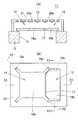
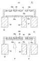
このような技術的背景のもとで、広いダイナミックレンジを有するマイクロフォンを実現する方法として、図1(A)及び図1(B)のような構造の音響センサを用いたものが提案されている。図1(A)は、従来例による音響センサ11の断面図であり、図1(B)は、そのバックプレート19を取り除いた状態の平面図である。 Under such a technical background, a method using an acoustic sensor having a structure as shown in FIGS. 1A and 1B has been proposed as a method for realizing a microphone having a wide dynamic range. . FIG. 1A is a sectional view of an
この音響センサ11では、空洞13を有する基板12の上方にスリット17で分割された第1ダイアフラム16aと第2ダイアフラム16bが配置されている。第1ダイアフラム16aは、比較的大きな面積を有していて、アンカー18aによって基板12の上面で支持されている。第2ダイアフラム16bは、比較的小さな面積を有していて、アンカー18bによって基板12の上面で支持されている。基板12の上面には、両ダイアフラム16a、16bを覆うようにしてバックプレート19が設けられ、その下面には、第1ダイアフラム16aと第2ダイアフラム16bに対向させて第1固定電極板20aと第2固定電極板20bが配置されている。バックプレート19及び固定電極板20a、20bには、多数のアコースティックホール21が開口されている。 In the
この音響センサ11においては、互いに対向した第1ダイアフラム16aと第1固定電極板20aによって小音量(小音圧)の音を検出することのできる高感度の第1音響センシング部14が構成されている。また、互いに対向した第2ダイアフラム16bと第2固定電極板20bによって大音量(大音圧)の音を検出することのできる低感度の第2音響センシング部15が構成されている。そして、音響センサ11からの出力を、音量に応じて第1音響センシング部14からの出力と、第2音響センシング部15からの出力とに切り替えるようにし、小さな音圧から大きな音圧までの音を高感度で検出するようにしている。このような音響センサとしては、たとえば特許文献1に開示されたものがある。 In the
しかし、このような静電容量型の音響センサ11では、ダイアフラム16a、16bに大きな圧力が加わると、ダイアフラム16a、16bやバックプレート19が破損することがある。ダイアフラム16a、16bに大きな圧力が加わる態様としては、たとえば音響センサ11の落下試験の場合に空洞13から入った空気の圧力がダイアフラム16a、16bに加わる場合、音響センサ11を組み込まれた携帯電話等の機器を落下させた場合、音響センサ11を組み込まれた携帯電話の送話口に強く息を吹き込んだ場合、送話口を指先などで叩いた場合などがある。これらの場合には、ダイアフラム16a、16bに数百Pa以上の圧力が加わることがある(音響センサの最大測定音圧は200Paまでである)。 However, in such a capacitive
たとえば図2は、ケーシング22に実装した音響センサ11を表している。ケーシング22には、音響センサ11の空洞13に対応させて音導入孔23を開口してあり、音響振動が音導入孔23を通って音響センサ11内に入り、第1ダイアフラム16a及び第2ダイアフラム16bで感知される構造となっている。この音響センサ11をケーシング22ごと床24に落下させた場合には、音導入孔23から入り込む空気流によって空洞13内の空気圧が高くなり、その圧力負荷によってダイアフラム16a、16bが大きく変形する。 For example, FIG. 2 shows the
このようにしてダイアフラム16a、16bに大きな圧力Pが加わると、図3(A)−図3(C)に示すように、圧力Pによってダイアフラム16a、16bが大きく撓み、ダイアフラム16a、16bがバックプレート19に衝突してバックプレート19も変形する。ここで、図3(A)、図3(B)及び図3(C)は、それぞれ図1(B)のX1−X1線に沿った概略断面図、X2−X2線に沿った概略断面図、X3−X3線に沿った概略断面図である。この結果、大きく変形することにより、あるいは衝突時の衝撃により、ダイアフラム16a、16bやバックプレート19が破損したり、亀裂が生じたりすることがあり、音響センサ11の破損耐性に問題があった。特に、図3(C)に示すように、大音量用の第2ダイアフラム16bでは、大音圧時に最適駆動するように面積を小さくし、剛性を高くしているために、急峻に変形し、大きな歪みが生じて破損しやすい。 When a large pressure P is applied to the
本発明の目的とするところは、音響振動検出時における周波数特性を維持しつつ、大きな空気圧が加わったときの振動電極板(ダイアフラム)の変形を抑制することによって応力集中や振動電極板及びバックプレートの破損を回避することのできる静電容量型の音響トランスデューサを提供することにある。 An object of the present invention is to suppress stress concentration, vibration electrode plate, and back plate by suppressing deformation of the vibration electrode plate (diaphragm) when large air pressure is applied while maintaining frequency characteristics at the time of acoustic vibration detection. It is an object of the present invention to provide a capacitive acoustic transducer capable of avoiding damage to the acoustic transducer.
本発明に係る音響トランスデューサは、空洞を有する基板と、前記基板の上方に配設された、圧力を逃がすための空隙部を有する振動電極板と、前記基板の上方において、前記振動電極板と対向するように配置された固定電極板と、前記振動電極板と前記固定電極板のうち少なくとも一方が複数領域に分割されていて、分割された各領域毎の前記振動電極板と前記固定電極板によって構成された複数のセンシング部と、前記振動電極板が変形していないときに前記空隙部を通過する空気圧の漏れを妨げ、前記振動電極板が圧力を受けて変形したときに前記空隙部が離れて前記空隙部を通過して圧力が逃げるように配置された漏れ圧調整部とを有することを特徴としている。ここで、空隙部とは、開口や窪み(切欠き)、孔、スリット状の隙間など、圧力を逃がすことができるようなものであればよい。 An acoustic transducer according to the present invention includes a substrate having a cavity, a vibrating electrode plate disposed above the substrate and having a gap for releasing pressure, and opposed to the vibrating electrode plate above the substrate. And at least one of the fixed electrode plate, the vibration electrode plate and the fixed electrode plate is divided into a plurality of regions, and the vibration electrode plate and the fixed electrode plate for each divided region The plurality of sensing units configured and the air gap passing through the gap when the vibrating electrode plate is not deformed are prevented, and the gap is separated when the vibrating electrode plate is deformed by receiving pressure. And a leakage pressure adjusting part arranged so that the pressure escapes through the gap. Here, the void portion may be anything that can release pressure, such as an opening, a depression (notch), a hole, or a slit-shaped gap.
本発明の音響トランスデューサにあっては、振動電極板に圧力を逃がすための空隙部を設けてあり、前記振動電極板が過剰な圧力によって変形していないときには漏れ圧調整部によって空隙部を通過する空気圧の漏れを妨げているので、通常の動作状態では空隙部から空気圧が逃げにくい。したがって、振動電極板に空隙部を設けているにも拘わらず、音響トランスデューサの低周波数領域における測定感度が低下しにくい。一方、振動電極板に過剰な圧力が加わって振動電極板が大きく変形すると、空隙部が開放されて空隙部から過剰な圧力(高負荷の圧力)が逃がされるので、過剰な圧力による振動電極板の変形が抑制される。そのため、音響トランスデューサを落下させたりして過剰な圧力が加わっても振動電極板が破損しにくくなる。 In the acoustic transducer according to the present invention, the vibration electrode plate is provided with a gap for releasing pressure, and when the vibration electrode plate is not deformed by excessive pressure, the gap is passed by the leak pressure adjustment unit. Since the air pressure is prevented from leaking, it is difficult for the air pressure to escape from the gap in a normal operation state. Therefore, the measurement sensitivity in the low-frequency region of the acoustic transducer is unlikely to decrease despite the provision of a gap in the vibrating electrode plate. On the other hand, if excessive pressure is applied to the vibration electrode plate and the vibration electrode plate is greatly deformed, the air gap is opened and excessive pressure (high load pressure) is released from the air gap. Is prevented from being deformed. Therefore, the vibration electrode plate is not easily damaged even if an excessive pressure is applied by dropping the acoustic transducer.
本発明に係る音響トランスデューサのある実施態様は、複数の前記センシング部は、それぞれ感度が異なる信号を出力することを特徴としている。かかる実施態様によれば、各センシング部からの信号を合成したり、切り替えたりすることにより音響トランスデューサのダイナミックレンジを広くすることができる。 An embodiment of the acoustic transducer according to the present invention is characterized in that the plurality of sensing units output signals having different sensitivities. According to this embodiment, the dynamic range of the acoustic transducer can be widened by synthesizing or switching signals from the sensing units.
本発明に係る音響トランスデューサの別な実施態様は、前記空隙部が、前記振動電極板を分割された各領域の間の隙間であることを特徴している。かかる実施態様によれば、前記振動電極板を前記隙間によって複数領域に分割することができる。したがって、空気圧を逃がすための空隙部が振動電極板を複数領域に分割させるための開口を兼ねることができ、振動電極板の構造を簡単にすることができる。また、振動電極板における総開口面積(空気圧を逃がすための空隙部の面積と振動電極板を分割するための開口の面積の和)が小さくなるので、音響トランスデューサの小型化に寄与するとともに振動電極板の強度も向上する。 Another embodiment of the acoustic transducer according to the present invention is characterized in that the gap is a gap between the regions obtained by dividing the vibration electrode plate. According to this embodiment, the vibrating electrode plate can be divided into a plurality of regions by the gap. Accordingly, the gap for releasing the air pressure can also serve as an opening for dividing the vibration electrode plate into a plurality of regions, and the structure of the vibration electrode plate can be simplified. In addition, since the total opening area in the vibrating electrode plate (the sum of the area of the gap for releasing air pressure and the area of the opening for dividing the vibrating electrode plate) is reduced, it contributes to downsizing of the acoustic transducer and the vibrating electrode The strength of the plate is also improved.
また、この実施態様においては、前記漏れ圧調整部が、変形していないときの前記振動電極板の前記隙間に納められた板状の部材であることを特徴としている。かかる態様では、通常の動作状態では隙間からの圧力の漏れを漏れ圧調整部で妨げているが、振動電極板が過剰な圧力によって大きく変形すると、振動電極板の隙間が漏れ圧調整部から離れて開かれ、圧力を逃がすことができるようになる。。 Further, in this embodiment, the leakage pressure adjusting portion is a plate-like member that is housed in the gap of the vibrating electrode plate when not deformed. In such a mode, in a normal operation state, leakage of pressure from the gap is prevented by the leakage pressure adjusting unit, but when the vibrating electrode plate is greatly deformed by excessive pressure, the gap of the vibrating electrode plate is separated from the leakage pressure adjusting unit. Open and let you relieve pressure. .
本発明に係る音響トランスデューサのさらに別な実施態様は、前記空隙部が、前記振動電極板に形成された開口であることを特徴としている。かかる実施態様における前記漏れ圧調整部は、変形していないときの前記振動電極板の前記開口に納められた板状の部材であってもよい。かかる実施態様では、通常の動作状態では開口からの圧力の漏れを漏れ圧調整部で妨げることができるが、振動電極板が過剰な圧力によって大きく変形すると、振動電極板の開口が漏れ圧調整部から離れて開かれ、開口から圧力を逃がすことができるようになる。 Yet another embodiment of the acoustic transducer according to the present invention is characterized in that the gap is an opening formed in the vibrating electrode plate. In this embodiment, the leakage pressure adjusting unit may be a plate-like member housed in the opening of the vibrating electrode plate when not deformed. In such an embodiment, in a normal operation state, the leakage of pressure from the opening can be prevented by the leakage pressure adjusting unit. However, when the vibrating electrode plate is greatly deformed by excessive pressure, the opening of the vibrating electrode plate becomes the leakage pressure adjusting unit. It can be opened away from it, allowing pressure to escape from the opening.
本発明に係る音響トランスデューサのさらに別な実施態様は、前記空隙部が、前記振動電極板の縁に形成された、振動電極板の内側へ向けて窪んだ窪みであることを特徴としている。かかる実施態様における前記漏れ圧調整部は、変形していないときの前記振動電極板の前記窪みに位置している板状の部材であってもよい。かかる実施態様では、通常の動作状態では窪みからの空気圧の漏れを漏れ圧調整部で妨げることができるが、振動電極板が過剰な圧力によって大きく変形すると、振動電極板の窪みが漏れ圧調整部から離れて開かれ、窪みから圧力を逃がすことができるようになる。 Yet another embodiment of the acoustic transducer according to the present invention is characterized in that the gap is a recess formed at an edge of the vibration electrode plate and recessed toward the inside of the vibration electrode plate. In this embodiment, the leakage pressure adjusting unit may be a plate-like member positioned in the depression of the vibrating electrode plate when not deformed. In such an embodiment, in a normal operation state, leakage of air pressure from the depression can be prevented by the leakage pressure adjustment unit, but when the vibration electrode plate is greatly deformed by excessive pressure, the depression of the vibration electrode plate becomes a leakage pressure adjustment unit. It can be opened away from it, allowing the pressure to escape from the recess.
本発明に係る音響トランスデューサのさらに別な実施態様は、前記漏れ圧調整部が、変形していない前記振動電極板の前記空隙部に位置しており、前記漏れ圧調整部の縁と前記空隙部の縁との間にスリットが形成されていることを特徴としている。漏れ圧調整部と空隙部の間にスリットが形成されていない場合には、漏れ圧調整部と振動電極板が一部で接触することになるので、振動電極板の振動が漏れ圧調整部によって妨げられ、音響トランスデューサの感度などに影響を与えるからである。また、このスリットの幅を10μm以下にすれば、音響トランスデューサの低収波数領域における感度の低下を十分に小さくできる。 Still another embodiment of the acoustic transducer according to the present invention is such that the leakage pressure adjusting portion is located in the gap portion of the vibrating electrode plate that is not deformed, and the edge of the leakage pressure adjusting portion and the gap portion It is characterized in that a slit is formed between the edges. If no slit is formed between the leakage pressure adjustment part and the gap, the leakage pressure adjustment part and the vibration electrode plate are in contact with each other, so the vibration of the vibration electrode plate is caused by the leakage pressure adjustment part. This is because it is disturbed and affects the sensitivity of the acoustic transducer. If the width of the slit is 10 μm or less, the decrease in sensitivity in the low wave number region of the acoustic transducer can be sufficiently reduced.
また、前記振動電極板を分割された各領域の間の隙間が漏れ圧調整部になっている実施態様においては、前記隙間を挟んで一方の側に位置する前記振動電極板の分割された領域と前記漏れ圧調整部の間に形成されたスリットの端と、前記隙間を挟んで他方の側に位置する前記振動電極板の分割された領域と前記漏れ圧調整部の間に形成されたスリットの端とが、90°の角度で交差していることが望ましい。かかる態様によれば、漏れ圧調整部に応力が集中しにくく、しかも隙間の一部に開口面積の大きな部分が生じるのを回避できる。 Further, in an embodiment in which a gap between the divided areas of the vibrating electrode plate is a leakage pressure adjusting unit, the divided area of the vibrating electrode plate located on one side with the gap interposed therebetween And an end of a slit formed between the leakage pressure adjusting unit, a slit formed between the divided region of the vibration electrode plate located on the other side across the gap and the leakage pressure adjusting unit It is desirable that the end of the crossing at an angle of 90 °. According to this aspect, it is difficult for stress to concentrate on the leakage pressure adjusting portion, and it is possible to avoid the occurrence of a portion having a large opening area in a part of the gap.
前記漏れ圧調整部の他の形態としては、変形していない前記振動電極板の前記空隙部の下面開口を塞ぐように位置する前記基板の上面の一部であってもよい。また、前記漏れ圧調整部は、変形していない前記振動電極板の前記空隙部の上面開口と下面開口のうち一方を塞ぐように前記振動電極板の上面側又は下面側に対向させて配置されていてもよい(なお、本願においては、漏れ圧調整部で塞ぐというときは、密閉を意味しない)。 As another form of the leakage pressure adjusting portion, it may be a part of the upper surface of the substrate positioned so as to close the lower surface opening of the gap portion of the vibration electrode plate that is not deformed. Further, the leakage pressure adjusting portion is arranged to face the upper surface side or the lower surface side of the vibration electrode plate so as to block one of the upper surface opening and the lower surface opening of the gap portion of the vibration electrode plate that is not deformed. (In this application, when it is closed with the leakage pressure adjusting portion, it does not mean sealing).
本発明に係る音響トランスデューサのさらに別な実施態様は、前記基板の上方に、前記振動電極板と対向するようにバックプレートが配置され、前記バックプレートの、前記振動電極板と対向する側の面に支持部が設けられ、前記漏れ圧調整部が、前記支持部に固定されていることを特徴としている。かかる実施態様によれば、漏れ圧調整部は過剰な圧力が加わっても変形しないので、過剰な圧力が加わったときには振動電極板の空隙部を確実に開放させることができる。 In another embodiment of the acoustic transducer according to the present invention, a back plate is disposed above the substrate so as to face the vibration electrode plate, and a surface of the back plate facing the vibration electrode plate is provided. A support portion is provided, and the leakage pressure adjusting portion is fixed to the support portion. According to such an embodiment, the leakage pressure adjusting portion does not deform even when an excessive pressure is applied. Therefore, when the excessive pressure is applied, the gap portion of the vibrating electrode plate can be reliably opened.
この場合、前記支持部の水平断面積は、前記漏れ圧調整部の面積よりも小さいことが望ましい。かかる態様によれば、支持部の外周面と振動電極板との間に圧力を逃がすための空間を確保することができる。 In this case, it is preferable that a horizontal cross-sectional area of the support portion is smaller than an area of the leak pressure adjusting portion. According to this aspect, it is possible to secure a space for releasing pressure between the outer peripheral surface of the support portion and the vibrating electrode plate.
また、前記漏れ圧調整部は、複数の前記支持部により支持されていてもよい。漏れ圧調整部を複数の支持部で支持してあれば、漏れ圧調整部の剛性が高くなるので、過剰な圧力が加わっても漏れ圧調整部が変形しにくくなる。 Further, the leakage pressure adjusting unit may be supported by a plurality of the supporting units. If the leakage pressure adjusting part is supported by a plurality of support parts, the rigidity of the leakage pressure adjusting part is increased, so that the leakage pressure adjusting part is not easily deformed even when excessive pressure is applied.
また、複数の支持部が設けられている場合には、前記支持部と前記支持部との中間において前記バックプレートに通孔を設けておいてもよい。かかる態様によれば、過剰な圧力をより効率的に外部へ逃がすことできる。 When a plurality of support portions are provided, a through hole may be provided in the back plate between the support portion and the support portion. According to this aspect, it is possible to escape the excessive pressure to the outside more efficiently.
また、前記漏れ圧調整部は、前記基板の上面に設けた支持部に固定されていてもよい。 Further, the leakage pressure adjusting part may be fixed to a support part provided on the upper surface of the substrate.
本発明に係る音響トランスデューサのさらに別な実施態様は、前記基板の上方に、前記振動電極板と対向するようにバックプレートが配置され、前記固定電極板が、前記振動電極板と対向するようにして前記バックプレートに設けられ、前記バックプレート及び前記固定電極板に複数のアコースティックホールが開口され、前記基板の上面に垂直な方向から見たとき、前記アコースティックホールの一部が前記空隙部と重なり合っていることを特徴としている。かかる実施態様によれば、過剰な圧力をスムーズに外部へ逃がすことができる。 In another embodiment of the acoustic transducer according to the present invention, a back plate is disposed above the substrate so as to face the vibration electrode plate, and the fixed electrode plate faces the vibration electrode plate. Provided in the back plate, and a plurality of acoustic holes are opened in the back plate and the fixed electrode plate, and when viewed from a direction perpendicular to the upper surface of the substrate, a part of the acoustic hole overlaps the gap portion. It is characterized by having. According to such an embodiment, excessive pressure can be smoothly released to the outside.
本発明に係る音響トランスデューサのさらに別な実施態様は、前記基板の上方に、前記振動電極板と対向するようにバックプレートが配置され、前記固定電極板が、前記振動電極板と対向するようにして前記バックプレートに設けられ、前記バックプレート及び前記固定電極板に複数のアコースティックホールが開口され、前記基板の上面に垂直な方向から見たとき、前記アコースティックホールの一部が前記スリットと重なり合っていることを特徴としている。かかる実施態様によれば、過剰な圧力を逃がす経路が短くなるので、過剰な圧力をよりスムーズに外部へ逃がすことができる。 In another embodiment of the acoustic transducer according to the present invention, a back plate is disposed above the substrate so as to face the vibration electrode plate, and the fixed electrode plate faces the vibration electrode plate. Provided in the back plate, and a plurality of acoustic holes are opened in the back plate and the fixed electrode plate, and when viewed from a direction perpendicular to the upper surface of the substrate, a part of the acoustic hole overlaps the slit. It is characterized by being. According to such an embodiment, the path through which excess pressure is released is shortened, so that excess pressure can be released to the outside more smoothly.
本発明に係る音響トランスデューサのさらに別な実施態様は、前記基板の上方に、前記振動電極板と対向するようにバックプレートが配置され、前記固定電極板が、前記振動電極板と対向するようにして前記バックプレートに設けられ、前記バックプレート及び前記固定電極板に複数のアコースティックホールが開口され、前記基板の上面に垂直な方向から見たとき、前記漏れ圧調整部の幅が前記アコースティックホール間の距離よりも大きいことを特徴としている。かかる実施態様によれば、漏れ圧調整部の上方に位置するアコースティックホールが振動電極板で塞がれにくくなり、過剰な圧力を確実に排出させることが可能になる。 In another embodiment of the acoustic transducer according to the present invention, a back plate is disposed above the substrate so as to face the vibration electrode plate, and the fixed electrode plate faces the vibration electrode plate. Provided in the back plate, and a plurality of acoustic holes are opened in the back plate and the fixed electrode plate, and when viewed from a direction perpendicular to the upper surface of the substrate, the width of the leakage pressure adjusting portion is between the acoustic holes. It is characterized by being larger than the distance. According to such an embodiment, the acoustic hole located above the leakage pressure adjusting unit is not easily blocked by the vibrating electrode plate, and it is possible to reliably discharge excess pressure.
本発明に係る音響トランスデューサのさらに別な実施態様は、前記基板の上方に、前記振動電極板と対向するようにバックプレートが配置され、前記固定電極板が、前記振動電極板と対向するようにして、かつ、前記漏れ圧調整部と対向しないようにして前記バックプレートに設けられていることを特徴としている。かかる実施態様によれば、漏れ圧調整部と固定電極板との間の寄生容量を小さくすることができる。 In another embodiment of the acoustic transducer according to the present invention, a back plate is disposed above the substrate so as to face the vibration electrode plate, and the fixed electrode plate faces the vibration electrode plate. In addition, the back plate is provided so as not to face the leakage pressure adjusting portion. According to such an embodiment, the parasitic capacitance between the leakage pressure adjusting unit and the fixed electrode plate can be reduced.
本発明に係る音響トランスデューサのさらに別な実施態様は、前記固定電極板が複数の領域に分割されており、分割された前記固定電極板の領域間に、電気的な信号の漏れを遮断するためのバリア電極を設けたことを特徴としている。かかる実施態様によれば、隣り合うセンシング部間で信号が漏れたり、ノイズが伝わったりすることを防止することができる。 In another embodiment of the acoustic transducer according to the present invention, the fixed electrode plate is divided into a plurality of regions, and electrical signal leakage is blocked between the divided regions of the fixed electrode plate. The barrier electrode is provided. According to this embodiment, it is possible to prevent signals from leaking or noise from being transmitted between adjacent sensing units.
本発明に係る音響トランスデューサのさらに別な実施態様は、前記基板の上方に、前記振動電極板と対向するようにバックプレートが配置され、前記振動電極板の、前記空隙部に隣接する領域に対向させて、前記バックプレートに突起を設けたことを特徴としている。かかる実施態様によれば、振動電極板が大きく変形した場合、突起に妨げられて振動電極板が固定電極板に固着しにくくなる。 In another embodiment of the acoustic transducer according to the present invention, a back plate is disposed above the substrate so as to face the vibration electrode plate, and faces a region adjacent to the gap portion of the vibration electrode plate. The back plate is provided with a protrusion. According to this embodiment, when the vibration electrode plate is greatly deformed, the vibration electrode plate is hardly fixed to the fixed electrode plate due to the protrusion.
本発明に係る音響トランスデューサのさらに別な実施態様は、前記振動電極板の、分割された各領域と前記漏れ圧調整部は、同一平面上にあり、かつ、同一材料によって形成されていることを特徴としている。かかる実施態様によれば、振動電極板と漏れ圧調整部を同一プロセスにより同時に作製することが可能になる。 Still another embodiment of the acoustic transducer according to the present invention is that each of the divided regions of the vibrating electrode plate and the leakage pressure adjusting unit are on the same plane and are formed of the same material. It is a feature. According to such an embodiment, the vibrating electrode plate and the leakage pressure adjusting unit can be simultaneously manufactured by the same process.
本発明に係る音響トランスデューサは、マイクロフォンに応用することができる。 The acoustic transducer according to the present invention can be applied to a microphone.
なお、本発明における前記課題を解決するための手段は、以上説明した構成要素を適宜組み合せた特徴を有するものであり、本発明はかかる構成要素の組合せによる多くのバリエーションを可能とするものである。 The means for solving the above-described problems in the present invention has a feature in which the above-described constituent elements are appropriately combined, and the present invention enables many variations by combining such constituent elements. .
以下、添付図面を参照しながら本発明の好適な実施形態を説明する。但し、本発明は以下の実施形態に限定されるものでなく、本発明の要旨を逸脱しない範囲において種々設計変更することができる。 Hereinafter, preferred embodiments of the present invention will be described with reference to the accompanying drawings. However, the present invention is not limited to the following embodiments, and various design changes can be made without departing from the gist of the present invention.
(実施形態1)
以下、図4−7を参照して本発明の実施形態1による音響センサの構造を説明する。図4は、本発明の実施形態1による音響トランスデューサ、すなわち音響センサ31の分解斜視図である。図5は、音響センサ31の断面図である。図6は、音響センサ31の平面図である。図7は、バックプレート38や保護膜50などを除いた音響センサ31の平面図であって、基板32の上方でダイアフラム33(振動電極板)と固定電極板39が重なった様子を表している。(Embodiment 1)
Hereinafter, the structure of the acoustic sensor according to the first embodiment of the present invention will be described with reference to FIGS. FIG. 4 is an exploded perspective view of the acoustic transducer, that is, the
この音響センサ31は、MEMS技術を利用して作製された静電容量型素子である。図4及び図5に示すように、この音響センサ31は、シリコン基板等の基板32の上面にアンカー36a、36bを介してダイアフラム33を設け、ダイアフラム33の上方に微小なエアギャップ40(空隙)を介して天蓋部34を配し、天蓋部34を基板32の上面に固定したものである。 The
基板32には、表面から裏面に貫通した空洞35(フロントチャンバ、バックチャンバ)が開口されている。図示の空洞35は、基板32の上面に垂直な面によって囲まれているが、空洞35の壁面は基板32の上面に対して傾いた面であってもよい。 In the
ダイアフラム33は、空洞35の上方を覆うようにして基板32の上方に配置されている。図4及び図7に示すように、ダイアフラム33は、略矩形状に形成されている。ダイアフラム33は、導電性を有するポリシリコン薄膜によって形成されていてダイアフラム33自体が振動電極板となっている。ダイアフラム33には、圧力を逃がすための空隙部、すなわちダイアフラム33の短辺と平行な方向に延びた開口33cが設けられており、ダイアフラム33は開口33cによって第1ダイアフラム33aと第2ダイアフラム33bに分割されている。第1ダイアフラム33aと第2ダイアフラム33bは、ダイアフラム33の一方の長辺で部分的につながっている。第1ダイアフラム33aと第2ダイアフラム33bはいずれも略矩形状となっているが、第1ダイアフラム33aは、第2ダイアフラム33bより大きな面積を有している。 The
第1ダイアフラム33aは、基板32の上面で、各コーナー部に設けられた脚片46をアンカー36aによって支持されており、基板32の上面から浮かせて支持されている。隣接するアンカー36a間において、第1ダイアフラム33aの外周部下面と基板32の上面との間には、音響振動を通過させるための狭いベントホール42aが形成されている。 The
第2ダイアフラム33bは、基板32の上面で、その両短辺をアンカー36bによって支持されており、基板32の上面から浮かせて支持されている。第2ダイアフラム33bの長辺下面と基板32の上面との間には、音響振動を通過させるための狭いベントホール42bが形成されている。ベントホール42aとベントホール42bは等しい高さの隙間となっている。 The
第1ダイアフラム33aと第2ダイアフラム33bの間の開口33cには、ポリシリコン薄膜からなる漏れ圧調整部37(以下、単に調整部37という。)が設けられている。調整部37は、図5に示すように、後述のバックプレート38から下方へ延出された複数本の支持部48により、バックプレート38の下方で水平に支持されている。調整部37の全周にはスリット状の隙間、すなわちスリット47(開口33cの一部)が形成されており、調整部37はスリット47によって第1ダイアフラム33aと完全に分離され、またスリット47によって第2ダイアフラム33bと完全に分離されている。 The
ダイアフラム33には、基板32の上面に設けられた引出配線49aが接続される。さらに、基板32の上面には、ダイアフラム33を囲むようにして帯状の土台部41が形成されている。アンカー36a、36b及び土台部41は、SiO2によって形成されている。A
図5に示すように、天蓋部34は、SiNからなるバックプレート38の下面に導電性を有するポリシリコン薄膜からなる固定電極板39を設けたものである。天蓋部34は、ドーム状に形成されていてその下に空洞部分を有しており、その空洞部分でダイアフラム33を覆っている。固定電極板39の下面とダイアフラム33の上面との間には微小なエアギャップ40(空隙)が形成されている。 As shown in FIG. 5, the
固定電極板39は、第1ダイアフラム33aと対向する第1固定電極板39aと、第2ダイアフラム33bと対向する第2固定電極板39bとに分割されていて、固定電極板39a、39bどうしは電気的に分離している。第1固定電極板39aは、第2固定電極板39bよりも大きな面積を有している。第1固定電極板39aからは引出配線49bが引き出されており、第2固定電極板39bからは引出配線49cが引き出されている。 The fixed
エアギャップ40を挟んで対向する第1ダイアフラム33aと第1固定電極板39aによってコンデンサ構造の第1音響センシング部43aが形成されている。また、エアギャップ40を挟んで対向する第2ダイアフラム33bと第2固定電極板39bによってコンデンサ構造の第2音響センシング部43bが形成されている。第1音響センシング部43aにおけるエアギャップ40のギャップ距離と、第2音響センシング部43bにおけるエアギャップ40のギャップ距離は等しい。 A first
バックプレート38と固定電極板39には、上面から下面に貫通するようにして、音響振動を通過させるためのアコースティックホール44(音響孔)が多数穿孔されている。なお、図示例においては、第1音響センシング部43aと第2音響センシング部43bで、アコースティックホール44の孔径とピッチが等しくなっているが、両音響センシング部43a、43bでアコースティックホール44の孔径やピッチが異なっている場合もある。 A large number of acoustic holes 44 (acoustic holes) are formed in the
図6及び図7に示すように、アコースティックホール44は、両音響センシング部43a、43bにおいて、それぞれ規則的に配列されている。図示例では、アコースティックホール44は、互いに120°の角度を成す3方向に沿って三角形状に配列されているが、矩形状や同心円状などに配置されていてもよい。 As shown in FIGS. 6 and 7, the
図5に示すように、第1音響センシング部43aでも第2音響センシング部43bでも、天蓋部34の下面には、円柱状をした微小なストッパ45(突起)が突出している。ストッパ45は、バックプレート38の下面から一体に突出しており、第1及び第2固定電極板39a、39bを貫通して天蓋部34の下面に突出している。ストッパ45はバックプレート38と同じくSiNからなるので、絶縁性を有する。このストッパ45は、静電気力によって各ダイアフラム33a、33bが各固定電極板39a、39bに固着して離れなくなるのを防ぐためのものである。また、調整部37と対向する箇所からは、前記のように複数本の支持部48が下方へ向けて延出されており、支持部48の下端には調整部37が水平に支持されている。 As shown in FIG. 5, in both the first
天蓋状をしたバックプレート38の外周縁からは、全周にわたって保護膜50が連続的に延出している。保護膜50は、土台部41とその外側のシリコン基板表面を覆っている。 From the outer peripheral edge of the canopy-shaped
保護膜50の上面には、共通電極パッド51、第1電極パッド52a、第2電極パッド52b及び接地電極パッド53が設けられている。ダイアフラム33に接続された引出配線49aの他端は、共通電極パッド51に接続されている。第1固定電極板39aから引き出された引出配線49bは、第1電極パッド52aに接続され、第2固定電極板39bから引き出された引出配線49cは、第2電極パッド52bに接続されている。また、接地電極パッド53は、基板32に接続されていて、接地電位に保たれる。 A
つぎに、音響センサ31が音響振動を感知しているときの動作と、ダイアフラム33に高負荷の大きな圧力が加わったときの音響センサ31の動作を説明する。図5は、音響センサ31の、ダイアフラム33に高負荷の圧力が加わっていない状態を示す断面図である。図9は、音響センサ31の、ダイアフラム33に高負荷の圧力が加わっている状態を示す概略断面図である。 Next, the operation when the
音響センサ31に高負荷の大きな圧力が加わっておらず、音響振動だけを感知している場合には、ダイアフラム33は図5のような平らな状態を中心として小さな振幅で上下に振動する。空洞35から音響センサ31内に入った音響振動に感応して各ダイアフラム33a、33bが振動すると、第1固定電極板39aと第1ダイアフラム33aによって構成される可変コンデンサの静電容量(第1音響センシング部43aの静電容量)が変化し、また第2固定電極板39bと第2ダイアフラム33bによって構成される可変コンデンサの静電容量(第2音響センシング部43bの静電容量)が変化する。この結果、各音響センシング部43a、43bにおいては、各ダイアフラム33a、33bが感知している音響振動(音圧の変化)がそれぞれの静電容量の変化となり、それぞれ感度の異なる電気的な信号として出力される。 When a large pressure with a high load is not applied to the
また、第2ダイアフラム33bの面積は第1ダイアフラム33aの面積よりも小さくなっているので、第2音響センシング部43bは中音量〜大音量までの音圧域用の低感度の音響センサとなっており、第1音響センシング部43aは小音量〜中音量までの音圧域用の高感度の音響センサとなっている。したがって、両音響センシング部43a、43bをハイブリッド化して処理回路によって信号を出力させることにより音響センサ31のダイナミックレンジを広げることができる。たとえば、第1音響センシング部43aのダイナミックレンジを約30−120dBとし、第2音響センシング部43bのダイナミックレンジを約50−140dBとすれば、両音響センシング部43a、43bを組み合わせることでダイナミックレンジを約30−140dBに広げることができる。また、音響センサ31を小音量〜中音量までの第1音響センシング部43aと中音量〜大音量までの第2音響センシング部43bに分けてあれば、第1音響センシング部43aの出力を大音量では使用しないようにでき、第1音響センシング部43aは大きな音圧域で高調波歪みが大きくなっても差し支えない。よって、第1音響センシング部43aの小音量に対する感度を高くすることができる。 Further, since the area of the
さらに、この音響センサ31では、第1音響センシング部43aと第2音響センシング部43bが同一基板上に形成されている。しかも、第1音響センシング部43aと第2音響センシング部43bが、ダイアフラム33を分割した第1ダイアフラム33a及び第2ダイアフラム33bと、固定電極板39を分割した第1固定電極板39a及び第2固定電極板39bとによって構成されている。すなわち、本来1つのセンシング部となるものを2つに分割して第1音響センシング部43aと第2音響センシング部43bをハイブリッド化しているので、1つの基板に独立した2つのセンシング部を設けた従来の音響センサや別々の基板にそれぞれセンシング部を設けた従来の音響センサに比較して、第1音響センシング部43aと第2音響センシング部43bは、検出感度に関するバラツキが類似することになる。その結果、両音響センシング部43a、43b間の検出感度バラツキを小さくできる。また、両音響センシング部43a、43bは、ダイアフラムと固定電極板を共用しているので、周波数特性、位相などの音響特性に関するミスマッチングを抑制することができる。 Furthermore, in this
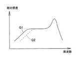
つぎに、調整部37と音響センサ31の周波数特性との関係について説明する。調整部37が存在しないと仮定すると、第1ダイアフラム33aと第2ダイアフラム33bの間に開口33cがあいた状態となるので、音響振動は狭いベントホール42a、42bを通るよりも開口33cを通り抜ける。そのため、ダイアフラム33の上面側と下面側との間の音響抵抗が小さくなる。ダイアフラム33に開口33cがあいていない場合の音響センサの周波数特性が図8に実線で示すカーブQ1であったとすると、開口があいている場合には、音響抵抗が小さくなるために図8に破線で示すカーブQ2のように低周波数領域で音響センサの感度が低下する。 Next, the relationship between the
本実施形態の音響センサ31では、第1ダイアフラム33aと第2ダイアフラム33bの間に開口33cがあけられているが、音響振動を感知する通常モードでは開口33cが調整部37によってほぼ塞がれているので、調整部37によって空気圧の漏れが妨げられて音響抵抗が低下しにくく、低周波数領域における音響センサの感度が低下しにくい。 In the
もっとも、両ダイアフラム33a、33bと調整部37とが接触していると、ダイアフラム33a、33bの振動が調整部37によって妨げられ、音響センサ31の感度が低下したり、S/N比が低下したりする恐れがある。そのため、調整部37の面積は開口33cの開口面積よりも若干小さくなっていて、ダイアフラム33a、33bと調整部37が分離されている。すなわち、開口33cの内周面と調整部37の外周面との間にはほぼ一定の幅wのスリット47が設けられている。 However, if the
一方、スリット47の幅wが広過ぎると、ベンチレーションの効果が強くなり、スリット47を介しての空気圧の抜けが大きくなり過ぎて、ロールオフ周波数の低下が発生し、低周波数特性が悪化する恐れがある。この点について以下に詳述する。 On the other hand, if the width w of the
前記図8は、MEMSマイクロフォンにおける典型的な周波数特性を示しており、同図の横軸は音響振動の周波数(単位:Hz)であり、縦軸は相対感度(単位:dB/dB)である。図8おいて、グラフが水平である範囲は、相対感度が音波の周波数に依存しない範囲であるので、音波を良好に検出できる範囲となる。この範囲の下限の周波数はロールオフ周波数froll-offと呼ばれる。 FIG. 8 shows a typical frequency characteristic in the MEMS microphone. In FIG. 8, the horizontal axis represents the frequency of acoustic vibration (unit: Hz), and the vertical axis represents the relative sensitivity (unit: dB / dB). . In FIG. 8, the range in which the graph is horizontal is a range in which the relative sensitivity does not depend on the frequency of the sound wave, so that the sound wave can be detected well. The lower limit frequency of this range is called the roll-off frequency froll-off.
一般に、ロールオフ周波数froll-offは、音響振動の通路における音響抵抗Rventhollと、空洞35内の空気のコンプライアンス(空気バネ定数)Cchamberとに依存し、次式で表される。
froll-off ∝ 1/(Rventholl×Cchamber) … 数式(1)In general, the roll-off frequency froll-off depends on the acoustic resistance Rventholl in the acoustic vibration path and the air compliance (air spring constant) Cchamber in the
froll-off 1 / 1 / (Rventholl × Cchamber)… Formula (1)
音響抵抗Rventhollは、スリット47の長さによっても影響されるが、スリット47の幅wが広いと低くなる。従って、上記数式(1)より、ロールオフ周波数froll-offが上昇してしまい、その結果、低周波数特性が悪化することになる。たとえば、スリット47の幅wが10μmであれば500Hz以上にもなる。このため、スリット47の幅wが10μmを超えると、低周波特性が著しく悪化し、音質が損なわれてしまうことになる。従って、スリット47の幅wは10μm以下であることが望ましい。 The acoustic resistance Rventholl is also affected by the length of the
つぎに、この音響センサ31の第1ダイアフラム33aと第2ダイアフラム33bに高負荷の圧力が加わったときの状態を図9により説明する。この音響センサ31が落下試験に掛けられた場合、音響センサ31を組み込まれた機器を落下させた場合、音響センサ31に強く息を吹き込んだ場合などには、各ダイアフラム33a、33bに高負荷の大きな圧力Pが加わる。音響センサ31に空洞35側から大きな圧力が加わった場合、第1ダイアフラム33aと第2ダイアフラム33bは弾力性が小さくて軟らかいので、大きな圧力Pを受けると大きく変形する。これに対し、調整部37は支持部48によって支持されているので両ダイアフラム33a、33bに追従して移動することはない。また、調整部37はダイアフラム33a、33bに比べて面積が小さくて硬いので、大きな圧力を受けてもダイアフラム33a、33bに追従して調整部37が変形することもない。そのため、第1ダイアフラム33aと第2ダイアフラム33bが大きく変形すると、調整部37が開口33cから抜け出て開口33cが開放され、支持部48の外周面と開口33cの縁との間に圧力Pを通過させるための空間が生じる。その結果、図9に示すように、圧力Pは開口33cとアコースティックホール44を通って外部へ逃げ、ダイアフラム33a、33bに加わる圧力が軽減されるので、ダイアフラム33a、33bの変形が小さくなる。そのため、ダイアフラム33a、33bがバックプレート38に加える衝撃も小さくなり、ダイアフラム33a、33bやバックプレート38に大きな応力が発生しにくくなって、ダイアフラム33a、33bやバックプレート38に破損や亀裂が発生しにくくなる(すなわち、破損耐性が向上する)。 Next, a state when a high load pressure is applied to the
これに対し、特許文献1の音響センサ11でも、第1ダイアフラム16aと第2ダイアフラム16bの間にはスリット17が設けられているが、大きな圧力を逃がすことができるようにスリット17の幅を広げると、音響抵抗が小さくなって音響センサ11の低周波数特性が悪化する。 On the other hand, in the
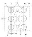
本実施形態の音響センサ31において、開口33cを通り抜けた圧力Pをアコースティックホール44から外部へスムーズに逃がすためには、図10に示すように、基板32の上面に垂直な方向から見たとき、アコースティックホール44の一部がダイアフラム33a、33bと調整部37との間のスリット47と重なり合っていることが望ましい。スリット47とアコースティックホール44が重なり合っておらず、図11(A)のように水平方向にずれている場合には、ダイアフラム33a、33bに加わった圧力Pの逃げる通路が長くなるので、圧力Pが逃げにくくなる。これに対し、図11(B)に示すように、スリット47とアコースティックホール44が重なり合っている場合には、ダイアフラム33a、33bに加わった圧力Pの逃げる通路が短くなるので、圧力Pが逃げやすくなり、ダイアフラム33a、33bに加わる圧力を効率よく低減させることができる。 In the
また、調整部37は、図10に示すように、その長さ方向に沿って配列された複数本の支持部48によってバックプレート38から吊り下げられている。さらに、バックプレート38には、支持部48と支持部48の間の各位置にそれぞれ1つ又は複数の通孔54を設けている。この通孔54は、アコースティックホール44の一部であってもよい。調整部37を複数本の支持部48によって支持すれば、調整部37の剛性を高めることができ、高負荷の圧力Pによって調整部37が変形しにくくなる。調整部37が圧力Pによって変形すると、調整部37とダイアフラム33a、33bの間の通路が狭くなるが、調整部37の剛性を高めて変形しにくくすれば、圧力Pの通路を確保することができる。しかも、支持部48と支持部48の間に通孔54を設けることにより、圧力Pをより効率的に逃がすことができるようになる。 Further, as shown in FIG. 10, the
また、支持部48の断面積は調整部37の面積よりも小さくなっており、特に支持部48の直径は調整部37の幅よりも短くなっている。このような構成によれば、図9に示すように、変形した第1ダイアフラム33a及び第2ダイアフラム33bの縁と支持部48の外周面との間に形成される、圧力Pを逃がすための通路を広くすることができる。さらに、図12(A)に示すように、調整部37の幅Dは、アコースティックホール44どうしの間の距離(縁どうしの距離)dよりも大きくなっている。図12(B)のように調整部37の幅Dがアコースティックホール44どうしの間の距離(縁どうしの距離)dよりも小さいとアコースティックホール44がダイアフラム33a。33bの縁で塞がれて圧力Pを逃がすための通路が塞がれるからである。 Further, the cross-sectional area of the
また、図13は、図7のZ部の拡大図である。第1ダイアフラム33aの縁と調整部37の間に形成されたスリット47の端部と、第2ダイアフラム33bの縁と調整部37の間に形成されたスリット47の端部との交差角度θは、図13のようにほぼ90°であることが望ましい。スリット47どうしの交差箇所が、図14(A)のように鋭角になっている場合には、音響センサ31の製造プロセスにおいてダイアフラム33や調整部37となるポリシリコン薄膜の残留応力により、製造プロセス中におけるポリシリコン薄膜や犠牲層などとの薄膜積層構造を破壊する可能性がある。また、ポリシリコン薄膜の応力集中を緩和させるために、図14(B)に示すように、図14(A)において鋭角となっている箇所にアールを施した場合には、スリット47中に開口面積の大きな箇所55が生じ、ここから音響振動が漏れ易くなり、音響センサ31の低周波数領域における特性が劣化する。これに対し、図13のように各スリット47を徐々に湾曲させながらスリット47の端部どうしが約90°の角度で交差するようにしてあれば、音響センサ31の低周波数領域における特性を劣化させることなく、ポリシリコン薄膜(調整部37)における応力集中を緩和させることができる。 FIG. 13 is an enlarged view of a Z portion in FIG. The crossing angle θ between the edge of the
つぎに、図5又は図9に示されているように、基板32の上面に垂直な方向から見たとき調整部37と重なり合う領域には、第1固定電極板39aも第2固定電極板39bも設けないことが望ましい。調整部37と固定電極板39が対向していると、両者の間に発生する寄生容量が大きくなるからである。 Next, as shown in FIG. 5 or FIG. 9, the first fixed
また、この実施形態では、第1ダイアフラム33aと第2ダイアフラム33bの中間に調整部37を配置しているので、第1音響センシング部43aと第2音響センシング部43bの間の距離を長くすることができる。特に、第1ダイアフラム33aと第2固定電極板39bとの距離や、第2ダイアフラム33bと第1固定電極板39aの距離を大きくすることができる。その結果、第1音響センシング部43aと第2音響センシング部43bの信号の相互干渉を低減させることができ、音響センサ31の高調波歪み率を小さくできる。さらに、第1ダイアフラム33aと第2ダイアフラム33bの中間に調整部37を配置しているので、調整部37を配置する開口33cがダイアフラム33a、33bどうしを分離させるための開口を兼ねることができ、高負荷の圧力Pを逃がすための開口33cの面積を大きくすることを可能にしつつも、開口33cの合理的な配置によって音響センサ31の小型化が可能になる。しかも、第1ダイアフラム33aや第2ダイアフラム33bの面積(電極面積)を大きく減少させることなく調整部37又は開口33cを配置することができるので、音響センサ31のサイズが同一であっても音響センサ31の感度低下を小さくできる。 Moreover, in this embodiment, since the
また、この実施形態では、ダイアフラム33が変形していない状態では、ダイアフラム33と調整部37が同一平面上にあって、スリット47で分離されているだけであるので、ダイアフラム33と調整部37を同一材料により、また同一の成膜プロセスによって作製することができ、製造プロセスを簡略化することができる。さらに、1回のフォトリソグラフィと1回のエッチングでスリット47を形成することができるので、幅の狭いスリット47を形成することができ、音響抵抗を小さくできる。 Further, in this embodiment, when the
さらに、バックプレート38の下面においては、第1ダイアフラム33aと第2ダイアフラム33bの縁部(特に、変位の大きな箇所)と対向する領域に、一部のストッパ45を配置している。この位置にストッパ45を設けることで、大きな圧力Pで大きく変形したダイアフラム33a、33bが固定電極板39a、39bに固着して離れなくなるのを防ぐことができる。 Further, on the lower surface of the
(実施形態1の変形例)
図15−図18により、本発明の実施形態1の変形例を説明する。図15(A)は、本発明の実施形態1の変形例による音響センサの、バックプレートを取り除いた状態を示す平面図である。この変形例では、第1ダイアフラム33aのほぼ中央部に円形の開口33cを設けている。第1ダイアフラム33aが変形していないときには、バックプレート38から垂下した支持部48の下端に設けられた円形の調整部37は、開口33c内に位置していて開口33cを塞いでいる。なお、スリット状開口56は、第1ダイアフラム33aと第2ダイアフラム33bを分割するためのものであって、ダイアフラム33の短辺方向と平行に延びている。(Modification of Embodiment 1)
A modification of the first embodiment of the present invention will be described with reference to FIGS. FIG. 15A is a plan view showing a state in which the back plate of the acoustic sensor according to the modification of the first embodiment of the present invention is removed. In this modification, a
図15(A)のような変形例では、ダイアフラム33に高負荷の圧力が加わると第1ダイアフラム33aと第2ダイアフラム33bが大きく変形するが、第1ダイアフラム33aが変形することで調整部37が開口33cから抜け出る。そのため開口33cから圧力Pが逃げ、第1ダイアフラム33aはもちろん第2ダイアフラム33bの変形も抑制される。 15A, when a high load pressure is applied to the
また、開口33c及び調整部37は、図15(B)に示す別な変形例のように、第2ダイアフラム33bのほぼ中央部に設けてもよい。あるいは、図示しないが、第1ダイアフラム33aと第2ダイアフラム33bの双方にそれぞれ開口33cと調整部37を設けても差し支えない。 Moreover, the
また、開口33c及び調整部37は、図16(A)に示すさらに別な変形例のように、矩形状又は多角形状であってもよい。なお、このとき開口33c及び調整部37の角部にアールを施しておけば、応力集中を緩和させてダイアフラム33や調整部37の破損を防ぐことができる。 Moreover, the
さらに、図16(B)に示すように、スリット状開口56と平行な方向に延びた、一方向に長い開口33cと調整部37をスリット状開口56の近傍に設けてもよい。 Further, as shown in FIG. 16B, an
図15(A)、図15(B)、図16(A)及び図16(B)のように第1ダイアフラム33a又は第2ダイアフラム33bの内部に開口33cを設けるようにすれば、ダイアフラム33の面積をより小さくできるので、音響センサ31の小型化に寄与できる。 If the
図7に示したダイアフラム33では、第1ダイアフラム33aと第2ダイアフラム33bは、図の下方で部分的につながっていたが、図17(A)に示すように、第1ダイアフラム33aと第2ダイアフラム33bが図の上方で部分的につながっていてもよい。また、図17(B)に示すように、は、第1ダイアフラム33aと第2ダイアフラム33bが図の上方及び下方で部分的につながっていてもよい。 In the
また、図18に示すように、第1ダイアフラム33aと第2ダイアフラム33bは、機械的及び電気的に完全に分離されていてもよい。この場合には、第1固定電極板39aと第2固定電極板39bは連続していても差し支えない。 Further, as shown in FIG. 18, the
(実施形態2)
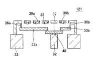
図19(A)は、本発明の実施形態2に係る音響センサ61の、バックプレート38を取り除いた状態を示す平面図である。図19(B)は、音響センサ61に高負荷の圧力Pが加わった状態を示す概略断面図である。実施形態2の音響センサ61では、図19(A)に示すように、ダイアフラム33の縁辺(外周部)に、ダイアフラム33の内側へ向けて切欠き状に窪んだ窪み62(圧力を逃がすための空隙部)を形成している。すなわち、第1ダイアフラム33aの、第2ダイアフラム33bと隣接していない縁辺において、脚片46と脚片46の間の領域に窪み62を設けている。あるいは、第2ダイアフラム33bの、第1ダイアフラム33aと隣接していない長辺に窪み62を設けてもよく、第1ダイアフラム33aと第2ダイアフラム33bの双方の縁辺に窪み62を設けてもよい。窪み62は、空洞35の近傍まで届いていることが好ましく、さらには空洞35の上方まで達していてもよい。そして、各窪み62には、調整部37が嵌り込むように位置している。調整部37は、ダイアフラム33と同じ高さに位置しており、ダイアフラム33a、33bとはスリット63によって分離されている。その他の構造や変形例については、実施形態1と同様である。たとえば、スリット63の幅が10μm以下であること、スリット63の真上に重なるようにアコースティックホール44が開口されていること、調整部37の鋭角となる部分にはアールを施すことが好ましいことなどである。(Embodiment 2)
FIG. 19A is a plan view showing a state where the
音響センサ61でも、空洞35側からダイアフラム33に高負荷の圧力Pが加わると、図19(B)に示すように、第1ダイアフラム33aや第2ダイアフラム33bの縁辺も浮き上がり、窪み62の位置に圧力を逃がすための空間が生じる。したがって、高負荷の圧力Pを逃がすことで第1ダイアフラム33aや第2ダイアフラム33bの変形を小さくでき、ダイアフラム33a、33bやバックプレート38の破損を回避できる。 Also in the
また、この実施形態では、第1ダイアフラム33aや第2ダイアフラム33bの電極として主要な働きをする領域(中央部)から外れた箇所に窪み62を設けているので、音響センサ61の感度に対する負の影響が小さくなる。ただし、この実施形態では、一つの窪み62の面積をあまり大きくすることができないので、窪み62を複数箇所に分けて設けることが望ましい。 Further, in this embodiment, since the
(実施形態3)
図20(A)は、本発明の実施形態3に係る音響センサ71の概略断面図である。図20(B)は、音響センサ71の、バックプレート38を取り除いた状態における平面図である。実施形態3の音響センサ71においては、バックプレート38の下面において、調整部37と対向する領域にバリア電極72を設けている。バリア電極72は、導電性を有するポリシリコン薄膜によって形成されており、音響センサ71の製造プロセスにおいては、第1固定電極板39a及び第2固定電極板39bと同一材料によって同一プロセスで作製される。バリア電極72は、第1ダイアフラム33aと第2ダイアフラム33bの境界に沿って、すなわち調整部37の長さ方向に沿ってほぼ端から端まで延びている。なお、バリア電極72はグランドに接続されていてもよく、またある電位に保たれていてもよい。(Embodiment 3)
FIG. 20A is a schematic cross-sectional view of an
このようなバリア電極72を設けてあれば、第1固定電極板39aから第2固定電極板39bへ、あるいは第2固定電極板39bから39aにノイズや信号が伝わるのを防止することができ、第1音響センシング部43aや第2音響センシング部43bのS/N比が低下したり、クロストークが生じるのを防ぐことができる。また、基板32の上面に垂直な方向から見たとき、バリア電極72と調整部37が重なり合うように設けることで、バリア電極72と調整部37を合理的に配置することができ、音響センサ71のサイズを小さくできる。 If such a
また、バリア電極72は、図21(A)及び図21(B)に示すように、調整部37から外れた位置において、調整部37と平行に設けてもよい。 Further, as shown in FIGS. 21A and 21B, the
(実施形態4)
上記各実施形態の音響センサでは、ダイアフラム33を第1ダイアフラム33aと第2ダイアフラム33bの2つの領域に分割していたが、ダイアフラム33は3つ以上の領域に分割されていてもよい。図22は、本発明の実施形態4に係る音響センサの、バックプレートを取り除いた状態における平面図であって、ダイアフラム33が3つの領域に分割されている。固定電極板39もダイアフラム33に応じて3つの領域に分割されており、その結果、音響センサは3つの音響センシング部を有している。(Embodiment 4)
In the acoustic sensor of each of the embodiments described above, the
図22に示すダイアフラム33では、最も面積の大きな第1ダイアフラム33aと、最も面積の小さな第2ダイアフラム33bと、中間の大きさの面積を有する第3ダイアフラム33dに分割されている。第1ダイアフラム33aと第2ダイアフラム33bは開口33cによって分割されており、第1ダイアフラム33aと第3ダイアフラム33dは開口33e(圧力を逃がすための空隙部)によって分割されている。各開口33c、33eには調整部37が納められており、各調整部37の周囲にはスリット47が形成されている。図示しないが、調整部37はいずれも、実施形態1の場合と同様に、バックプレート38から下方へ垂下された支持部48の下端で水平に支持されている。 The
最も面積の大きな第1ダイアフラム33aは、対応する固定電極板とペアになって、小音量用の高感度のセンシング部を構成する。最も面積の小さな第2ダイアフラム33bは、対応する固定電極板とペアになって、大音量用の低感度のセンシング部を構成する。中間の大きさの面積を有する第3ダイアフラム33dは、対応する固定電極板とペアになって、中音量用の中感度のセンシング部を構成する。よって、この実施形態によれば、音響センサに広いダイナミックレンジを持たせることができる。 The
この音響センサでも、たとえば音響センサを落下させてダイアフラム33a、33b、33dが変形すると、開口33c、33eが開いて高負荷の圧力が逃げ、ダイアフラム33a、33b、33dの変形が抑制され、ダイアフラム33a、33b、33dやバックプレート38の破損が防止される。 Even in this acoustic sensor, for example, when the acoustic sensor is dropped and the
(実施形態5)
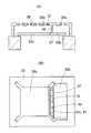
図23は、本発明の実施形態5に係る音響センサ81の断面図であって、固定電極板39a、39bの上方にダイアフラム33a、33bを設けたことを特徴としている。音響センサ81では、基板32の上面に絶縁層82を介して平板状のバックプレート38を設けている。バックプレート38の上面には、固定電極板39a、39bが形成されている。空洞35の上方において、バックプレート38及び固定電極板39a、39bには複数のアコースティックホール44が開口されている。また、バックプレート38の上方には、固定電極板39a、39bと対向させるようにしてダイアフラム33a、33bが配設されている。ダイアフラム33a、33bは、バックプレート38の上面に設けられたアンカー36a、36bによって支持されている。(Embodiment 5)
FIG. 23 is a cross-sectional view of an
ダイアフラムは、たとえば実施形態1の音響センサ31に用いられているダイアフラム33と同じ構造を有している。すなわち、ダイアフラムは第1ダイアフラム33aと第2ダイアフラム33bに分割されており、第1ダイアフラム33aと第2ダイアフラム33bの間には開口33cが設けられている。この開口33c内には調整部37が納められており、調整部37は、バックプレート38の上面に立てられた支持部48の上端に固定されている。 The diaphragm has the same structure as the
(実施形態6)
上記各実施形態では、通常の動作状態においては、ダイアフラム33に設けた開口33cが調整部37でほぼ塞がれるようにしているが、圧力を逃がすための空隙部である開口33cを基板32の上面で覆って開口33cにおける空気圧の漏れを妨げるようにすることも可能である。(Embodiment 6)
In each of the above embodiments, in a normal operation state, the
図24(A)は、本発明の実施形態6に係る音響センサ91の概略断面図である。図24(B)は、音響センサ91において、両ダイアフラムに下方から高負荷の大きな圧力が加わったときの状態を示す概略断面図である。また、図25(A)は、音響センサ91の、バックプレートを取り除いた状態における平面図である。図25(B)は、音響センサ91に用いられている基板32の平面図である。 FIG. 24A is a schematic cross-sectional view of an
この音響センサ91においては、図25(A)に示すように、ダイアフラム33が第1ダイアフラム33aと第2ダイアフラム33bに分割され、両ダイアフラム33a、33bの間に開口33cが形成されている。一方、基板32の空洞35内には、図25(B)に示すように、開口33cの長さ方向と平行に仕切壁状又は梁状の張出部92が設けられており、開口33cの下面を基板32の上面、すなわち張出部92の上面で塞いでいる。したがって、この基板32の上面の一部、すなわち張出部92の上面が調整部37となっている。 In the
この音響センサ91では、通常の音響振動を感知している場合には、図24(A)のように開口33cにおける空気圧の漏れが基板32(張出部92)の上面で妨げられているので、音響センサ91の音響抵抗が低下しにくく、音響センサ91の低周波数領域における特性を維持することができる。これに対し、ダイアフラム33に下方から高負荷の圧力Pが加わった場合には、図24(B)のようにダイアフラム33a、33bが上方へ浮き上がるので、開口33cが開放されて開口33cから圧力Pが逃げるようになる。 In this
(実施形態7)
図26(A)は、本発明の実施形態7の変形例による音響センサ101の概略断面図である。図26(B)は、音響センサ101の、バックプレートを取り除いた状態における平面図である。この音響センサ101では、開口33c内に位置する調整部37を基板32の上面、すなわち張出部92の上面に設けた支持部48の上面に固定している。また、ダイアフラム33の脚片46や第2ダイアフラム33bの両端部は、バックプレート38の下面から下方へ向けて延出されたアンカー36a、36bの下端に固定されている。(Embodiment 7)
FIG. 26A is a schematic cross-sectional view of an
(実施形態8)
電極部分は矩形状のものに限らず、円形のものであってもよい。図27は、本発明の実施形態8に係る音響センサ111を示す平面図である。図28は、音響センサ111の断面図である。図29(A)は、音響センサ111においてバックプレート38の下面に設けられた固定電極板39a、39bとバリア電極72を示す平面図である。図29(B)は、音響センサ111に用いられるダイアフラム33の平面図である。(Embodiment 8)
The electrode portion is not limited to a rectangular shape, and may be a circular shape. FIG. 27 is a plan view showing an
この音響センサ111にあっては、図28に示すように、基板32の上面に円板状のダイアフラム33を設けている。円形のダイアフラム33の外周部からは1本の脚片46が延出されており、ダイアフラム33はアンカー36によって支持された脚片46によって片持ち状に支持されている。ダイアフラム33の中央部には、図29(B)に示すように開口33cが開口されている。また、図27及び図29(B)に示すように、脚片46からは引出配線49aが延出され、引出配線49aは共通電極パッド51に接続されている。ダイアフラム33の開口33c内には調整部37が配置されていて、開口33cが調整部37によって塞がれている。ただし、ダイアフラム33と調整部37が接触して干渉を起こさないよう、両者の間にはスリット47が形成されている。調整部37は、たとえばバックプレート38から下方へ延びた支持部48によって水平に支持されている。 In the
一方、図28及び図29(A)に示すように、バックプレート38の下面中央部には円板状の第1固定電極板39aが設けられている。第1固定電極板39aの外側には、第1固定電極板39aと接触しないようにして円環状のバリア電極72が設けられている。バリア電極72の外側には、バリア電極72と接触しないようにして、円環状の第2固定電極板39bが設けられている。図27及び図29(A)に示すように、第1固定電極板39aの外周部からは、引出配線49bが延出され、引出配線49bは第1電極パッド52aに接続されている。第2固定電極板39bからは、引出配線49cが延出され、引出配線49cは第2電極パッド52bに接続されている。 On the other hand, as shown in FIGS. 28 and 29A, a disc-shaped first fixed
この音響センサ111では、ダイアフラム33の中央部と第1固定電極板39aによって円形をした小音量・高感度の音響センシング部が構成されている。また、ダイアフラム33の外周部と第2固定電極板39bによって円環状をした大音量・低感度の音響センシング部が構成されている。 In the
また、音響センサ111でも、ダイアフラム33に高負荷の圧力が加わった場合には、ダイアフラム33が大きく変形して開口33cが開放され、開口33cから高負荷の圧力が逃がされる。 In the
(実施形態9)
図30は、本発明の実施形態9による音響センサ121の構造を示す概略断面図である。実施形態6(図24)の音響センサ91では、基板32の上面を空隙部(開口33c)の下面開口に対向させて空気圧の漏れを妨げていたが、基板とは別部材の漏れ圧調整部37を用いてもよい。すなわち、板状または薄膜状の漏れ圧調整部37を変形していないダイアフラム33の空隙部の上面開口と下面開口のうち一方をほぼ塞ぐようにダイアフラム33の上面側又は下面側に対向させて配置してもよい。図30の図示例では、基板32の上面に設けた支持部48によって漏れ圧調整部37を固定し、漏れ圧調整部37で第1ダイアフラム33aと第2ダイアフラム33bの間の開口33cを下面側から遮っている。(Embodiment 9)
FIG. 30 is a schematic sectional view showing the structure of the
(マイクロフォンへの応用)
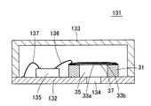
図31は、本発明に係る音響センサ、たとえば実施形態1の音響センサ31を内蔵したボトムポート型のマイクロフォン131の概略断面図である。このマイクロフォン131は、回路基板132とカバー133からなるパッケージ内に音響センサ31と回路部である信号処理回路135(ASIC)とを内蔵したものである。音響センサ31と信号処理回路135は、回路基板132の上面に実装されている。回路基板132には、音響センサ31内に音響振動を導き入れるための音導入孔134が開口されている。音響センサ31は、空洞35の下面開口を音導入孔134に合わせ、音導入孔134を覆うようにして回路基板132の上面に実装されている。したがって、音響センサ31の空洞35がフロントチャンバとなり、パッケージ内の空間がバックチャンバとなる。(Application to microphone)
FIG. 31 is a schematic cross-sectional view of a bottom
音響センサ31と信号処理回路135は、ボンディングワイヤ136によって接続されている。さらに、信号処理回路135は、ボンディングワイヤ137によって回路基板132に接続されている。なお、信号処理回路135は、音響センサ31へ電源を供給する機能や、音響センサ31の容量変化信号を外部へ出力する機能を有する。 The
回路基板132の上面には、音響センサ31及び信号処理回路135を覆うようにしてカバー133が取り付けられる。パッケージは電磁シールドの機能を有しており、外部からの電気的な外乱や機械的な衝撃から音響センサ31や信号処理回路135を保護している。 A
こうして、音導入孔134から空洞35内に入った音響振動は、音響センサ31によって検出され、信号処理回路135によって増幅及び信号処理された後に出力される。このマイクロフォン131では、パッケージ内の空間をバックチャンバとしているので、バックチャンバの容積を大きくでき、マイクロフォン131を高感度化することができる。 Thus, the acoustic vibration that has entered the
なお、このマイクロフォン131においては、パッケージ内に音響振動を導き入れるための音導入孔134をカバー133の上面に開口していてもよい。この場合には、音響センサ31の空洞35がバックチャンバとなり、パッケージ内の空間がフロントチャンバとなる。 In the
31、61、71、81、91、101、111 音響センサ
32 基板
33 ダイアフラム
33a 第1ダイアフラム
33b 第2ダイアフラム
33d 第3ダイアフラム
33c、33e 開口
35 空洞
37 調整部(漏れ圧調整部)
38 バックプレート
39 固定電極板
39a 第1固定電極板
39b 第2固定電極板
43a 第1音響センシング部
43b 第2音響センシング部
44 アコースティックホール
45 ストッパ
47 スリット
48 支持部
54 通孔
62 窪み
63 スリット
72 バリア電極
92 張出部
131 マイクロフォン31, 61, 71, 81, 91, 101, 111
38
Claims (28)
Translated fromJapanese前記基板の上方に配設された、圧力を逃がすための空隙部を有する振動電極板と、
前記基板の上方において、前記振動電極板と対向するように配置された固定電極板と、
前記振動電極板と前記固定電極板のうち少なくとも一方が複数領域に分割されていて、分割された各領域毎の前記振動電極板と前記固定電極板によって構成された複数のセンシング部と、
前記振動電極板が変形していないときに前記空隙部を通過する空気圧の漏れを妨げ、前記振動電極板が圧力を受けて変形したときに前記空隙部が離れて前記空隙部を通過して圧力が逃げるように配置された漏れ圧調整部と、
を有することを特徴とする音響トランスデューサ。A substrate having a cavity;
A vibrating electrode plate disposed above the substrate and having a gap for releasing pressure;
Above the substrate, a fixed electrode plate disposed to face the vibrating electrode plate;
At least one of the vibration electrode plate and the fixed electrode plate is divided into a plurality of regions, and a plurality of sensing units configured by the vibration electrode plate and the fixed electrode plate for each divided region,
When the vibrating electrode plate is not deformed, air pressure leakage through the gap is prevented, and when the vibrating electrode plate is deformed by pressure, the gap is separated and passes through the gap. A leakage pressure adjusting portion arranged to escape,
An acoustic transducer comprising:
前記漏れ圧調整部の縁と前記空隙部の縁との間にスリットが形成されていることを特徴とする、請求項1に記載の音響トランスデューサ。The leakage pressure adjusting portion is located in the gap portion of the vibrating electrode plate that is not deformed;
The acoustic transducer according to claim 1, wherein a slit is formed between an edge of the leakage pressure adjusting unit and an edge of the gap.
前記バックプレートの、前記振動電極板と対向する側の面に支持部が設けられ、
前記漏れ圧調整部が、前記支持部に固定されていることを特徴とする、請求項1に記載の音響トランスデューサ。A back plate is disposed above the substrate so as to face the vibration electrode plate,
A support portion is provided on a surface of the back plate that faces the vibration electrode plate,
The acoustic transducer according to claim 1, wherein the leakage pressure adjusting unit is fixed to the support unit.
前記固定電極板が、前記振動電極板と対向するようにして前記バックプレートに設けられ、
前記バックプレート及び前記固定電極板に複数のアコースティックホールが開口され、
前記基板の上面に垂直な方向から見たとき、前記アコースティックホールの一部が前記空隙部と重なり合っていることを特徴とする、請求項1に記載の音響トランスデューサ。A back plate is disposed above the substrate so as to face the vibration electrode plate,
The fixed electrode plate is provided on the back plate so as to face the vibration electrode plate;
A plurality of acoustic holes are opened in the back plate and the fixed electrode plate,
2. The acoustic transducer according to claim 1, wherein when viewed from a direction perpendicular to the upper surface of the substrate, a part of the acoustic hole overlaps the gap portion.
前記固定電極板が、前記振動電極板と対向するようにして前記バックプレートに設けられ、
前記バックプレート及び前記固定電極板に複数のアコースティックホールが開口され、
前記基板の上面に垂直な方向から見たとき、前記アコースティックホールの一部が前記スリットと重なり合っていることを特徴とする、請求項10に記載の音響トランスデューサ。A back plate is disposed above the substrate so as to face the vibration electrode plate,
The fixed electrode plate is provided on the back plate so as to face the vibration electrode plate;
A plurality of acoustic holes are opened in the back plate and the fixed electrode plate,
The acoustic transducer according to claim 10, wherein when viewed from a direction perpendicular to the upper surface of the substrate, a part of the acoustic hole overlaps the slit.
前記固定電極板が、前記振動電極板と対向するようにして前記バックプレートに設けられ、
前記バックプレート及び前記固定電極板に複数のアコースティックホールが開口され、
前記基板の上面に垂直な方向から見たとき、前記漏れ圧調整部の幅が前記アコースティックホール間の距離よりも大きいことを特徴とする、請求項1に記載の音響トランスデューサ。A back plate is disposed above the substrate so as to face the vibration electrode plate,
The fixed electrode plate is provided on the back plate so as to face the vibration electrode plate;
A plurality of acoustic holes are opened in the back plate and the fixed electrode plate,
2. The acoustic transducer according to claim 1, wherein when viewed from a direction perpendicular to the upper surface of the substrate, the width of the leakage pressure adjusting unit is larger than a distance between the acoustic holes.
前記固定電極板が、前記振動電極板と対向するようにして、かつ、前記漏れ圧調整部と対向しないようにして前記バックプレートに設けられていることを特徴とする、請求項1に記載の音響トランスデューサ。A back plate is disposed above the substrate so as to face the vibration electrode plate,
2. The back plate according to claim 1, wherein the fixed electrode plate is provided on the back plate so as to face the vibration electrode plate and not to face the leakage pressure adjusting unit. Acoustic transducer.
分割された前記固定電極板の領域間に、電気的な信号の漏れを遮断するためのバリア電極が設けられていることを特徴とする、請求項1に記載の音響トランスデューサ。The fixed electrode plate is divided into a plurality of regions;
The acoustic transducer according to claim 1, wherein a barrier electrode for blocking leakage of an electrical signal is provided between the divided fixed electrode plate regions.
前記振動電極板の、前記空隙部に隣接する領域に対向させて、前記バックプレートに突起を設けていることを特徴とする、請求項1に記載の音響トランスデューサ。A back plate is disposed above the substrate so as to face the vibration electrode plate,
The acoustic transducer according to claim 1, wherein a projection is provided on the back plate so as to face a region adjacent to the gap portion of the vibrating electrode plate.
Priority Applications (3)
| Application Number | Priority Date | Filing Date | Title |
|---|---|---|---|
| JP2013190303AJP6179297B2 (en) | 2013-09-13 | 2013-09-13 | Acoustic transducer and microphone |
| CN201410444586.0ACN104469640B (en) | 2013-09-13 | 2014-09-03 | Sound converter and microphone |
| US14/482,693US9549263B2 (en) | 2013-09-13 | 2014-09-10 | Acoustic transducer and microphone |
Applications Claiming Priority (1)
| Application Number | Priority Date | Filing Date | Title |
|---|---|---|---|
| JP2013190303AJP6179297B2 (en) | 2013-09-13 | 2013-09-13 | Acoustic transducer and microphone |
Publications (2)
| Publication Number | Publication Date |
|---|---|
| JP2015056833A JP2015056833A (en) | 2015-03-23 |
| JP6179297B2true JP6179297B2 (en) | 2017-08-16 |
Family
ID=52668003
Family Applications (1)
| Application Number | Title | Priority Date | Filing Date |
|---|---|---|---|
| JP2013190303AActiveJP6179297B2 (en) | 2013-09-13 | 2013-09-13 | Acoustic transducer and microphone |
Country Status (3)
| Country | Link |
|---|---|
| US (1) | US9549263B2 (en) |
| JP (1) | JP6179297B2 (en) |
| CN (1) | CN104469640B (en) |
Cited By (1)
| Publication number | Priority date | Publication date | Assignee | Title |
|---|---|---|---|---|
| US12219311B2 (en) | 2021-07-27 | 2025-02-04 | Samsung Electronics Co., Ltd. | Electronic device having plurality of acoustic ducts |
Families Citing this family (37)
| Publication number | Priority date | Publication date | Assignee | Title |
|---|---|---|---|---|
| CA2900661A1 (en)* | 2013-03-13 | 2014-09-18 | Rolls-Royce North American Technologies, Inc. | Gas turbine engine and electrical system |
| KR101463429B1 (en)* | 2014-08-20 | 2014-11-20 | 한국지질자원연구원 | Apparatus of detecting infrasound |
| US9807532B2 (en)* | 2015-05-22 | 2017-10-31 | Kathirgamasundaram Sooriakumar | Acoustic apparatus, system and method of fabrication |
| JP6582274B2 (en)* | 2015-09-28 | 2019-10-02 | 新日本無線株式会社 | MEMS element |
| CN105357617B (en)* | 2015-11-30 | 2019-08-09 | 歌尔股份有限公司 | A kind of MEMS microphone chip and its manufacturing method and MEMS microphone |
| US9998820B2 (en)* | 2016-01-19 | 2018-06-12 | Donald Pierce Bearden | Acoustic resonator for audio headphones |
| GB2546827B (en)* | 2016-01-28 | 2020-01-29 | Cirrus Logic Int Semiconductor Ltd | MEMS device and process |
| JP6658126B2 (en) | 2016-03-10 | 2020-03-04 | オムロン株式会社 | Capacitive transducer and acoustic sensor |
| JP6701825B2 (en)* | 2016-03-10 | 2020-05-27 | オムロン株式会社 | Capacitive transducer and acoustic sensor |
| JP6645278B2 (en) | 2016-03-10 | 2020-02-14 | オムロン株式会社 | Capacitive transducer and acoustic sensor |
| CN107548000B (en)* | 2016-06-29 | 2019-12-03 | 中芯国际集成电路制造(北京)有限公司 | A kind of MEMS microphone and preparation method thereof |
| CN106375912B (en)* | 2016-08-31 | 2020-03-17 | 歌尔股份有限公司 | Vibrating diaphragm in MEMS microphone and MEMS microphone |
| KR101916052B1 (en)* | 2016-09-09 | 2018-11-07 | 현대자동차 주식회사 | Microphone, manufacturing method and control method therefor |
| IT201600121533A1 (en)* | 2016-11-30 | 2018-05-30 | St Microelectronics Srl | MEMS INTEGRATED ELECTROACOUSTIC TRANSDUCER WITH IMPROVED SENSITIVITY AND RELATIVE PROCESS OF MANUFACTURING |
| JP6930101B2 (en)* | 2016-12-12 | 2021-09-01 | オムロン株式会社 | Acoustic sensors and capacitive transducers |
| CN108632689A (en)* | 2017-03-24 | 2018-10-09 | 中芯国际集成电路制造(上海)有限公司 | Microphone and production method |
| GB2560774B (en) | 2017-03-24 | 2019-11-13 | Cirrus Logic Int Semiconductor Ltd | MEMS devices and processes |
| IT201700103511A1 (en)* | 2017-09-15 | 2019-03-15 | St Microelectronics Srl | MICROELECTRONIC DEVICE EQUIPPED WITH PROTECTED CONNECTIONS AND RELATIVE PROCESS OF MANUFACTURE |
| CN108650606B (en)* | 2018-06-25 | 2020-05-29 | 歌尔股份有限公司 | Microphone (CN) |
| JP2020036215A (en)* | 2018-08-30 | 2020-03-05 | Tdk株式会社 | MEMS microphone |
| JP2020036214A (en)* | 2018-08-30 | 2020-03-05 | Tdk株式会社 | MEMS microphone |
| CN209218393U (en)* | 2018-09-26 | 2019-08-06 | 瑞声声学科技(深圳)有限公司 | MEMS microphone |
| US11206494B2 (en) | 2018-10-05 | 2021-12-21 | Knowles Electronics, Llc | Microphone device with ingress protection |
| WO2020072938A1 (en) | 2018-10-05 | 2020-04-09 | Knowles Electronics, Llc | Methods of forming mems diaphragms including corrugations |
| WO2020072904A1 (en)* | 2018-10-05 | 2020-04-09 | Knowles Electronics, Llc | Acoustic transducers with a low pressure zone and diaphragms having enhanced compliance |
| CN110784814A (en)* | 2019-10-30 | 2020-02-11 | 歌尔股份有限公司 | Microphone and electronic equipment |
| TWI770543B (en)* | 2020-06-29 | 2022-07-11 | 美律實業股份有限公司 | Microphone structure |
| CN111757228A (en)* | 2020-07-06 | 2020-10-09 | 瑞声科技(南京)有限公司 | MEMS microphone |
| US12240748B2 (en) | 2021-03-21 | 2025-03-04 | Knowles Electronics, Llc | MEMS die and MEMS-based sensor |
| US11528546B2 (en) | 2021-04-05 | 2022-12-13 | Knowles Electronics, Llc | Sealed vacuum MEMS die |
| US11540048B2 (en) | 2021-04-16 | 2022-12-27 | Knowles Electronics, Llc | Reduced noise MEMS device with force feedback |
| US11649161B2 (en) | 2021-07-26 | 2023-05-16 | Knowles Electronics, Llc | Diaphragm assembly with non-uniform pillar distribution |
| US11772961B2 (en) | 2021-08-26 | 2023-10-03 | Knowles Electronics, Llc | MEMS device with perimeter barometric relief pierce |
| US11780726B2 (en) | 2021-11-03 | 2023-10-10 | Knowles Electronics, Llc | Dual-diaphragm assembly having center constraint |
| CN114234543B (en)* | 2021-12-22 | 2022-12-23 | 珠海格力电器股份有限公司 | Shelf assembly and refrigerator |
| US20240114286A1 (en)* | 2022-10-03 | 2024-04-04 | Sound Devices Llc | Digital lavalier microphone |
| TWI863292B (en)* | 2023-05-22 | 2024-11-21 | 星瑞半導體股份有限公司 | Micro-electro-mechanical system device |
Family Cites Families (17)
| Publication number | Priority date | Publication date | Assignee | Title |
|---|---|---|---|---|
| EP0294102B1 (en)* | 1987-06-04 | 1994-10-12 | Seiko Instruments Inc. | Travelling-wave motor |
| US6088463A (en)* | 1998-10-30 | 2000-07-11 | Microtronic A/S | Solid state silicon-based condenser microphone |
| US7346178B2 (en)* | 2004-10-29 | 2008-03-18 | Silicon Matrix Pte. Ltd. | Backplateless silicon microphone |
| JP4539450B2 (en)* | 2004-11-04 | 2010-09-08 | オムロン株式会社 | Capacitive vibration sensor and manufacturing method thereof |
| WO2006123263A1 (en)* | 2005-05-17 | 2006-11-23 | Nxp B.V. | Improved membrane for a mems condenser microphone |
| US7804969B2 (en)* | 2006-08-07 | 2010-09-28 | Shandong Gettop Acoustic Co., Ltd. | Silicon microphone with impact proof structure |
| US7903835B2 (en)* | 2006-10-18 | 2011-03-08 | The Research Foundation Of State University Of New York | Miniature non-directional microphone |
| US20080192962A1 (en)* | 2007-02-13 | 2008-08-14 | Sonion Nederland B.V. | Microphone with dual transducers |
| US8625824B2 (en)* | 2007-09-04 | 2014-01-07 | Industrial Technology Research Institute | Flat speaker unit and speaker device therewith |
| JP5070026B2 (en)* | 2007-12-17 | 2012-11-07 | 新日本無線株式会社 | Condenser microphone and manufacturing method thereof |
| DE102009026677A1 (en)* | 2009-06-03 | 2010-12-09 | Robert Bosch Gmbh | Semiconductor component with a micromechanical microphone structure |
| US20110030035A1 (en)* | 2009-07-31 | 2011-02-03 | Chih-Hsiang Wu | Method of managing authorization of private node b in a wireless communication system and related device |
| CN201663687U (en)* | 2009-10-29 | 2010-12-01 | 苏州敏芯微电子技术有限公司 | Capacitance type micro-silicon microphone |
| JP5872163B2 (en)* | 2011-01-07 | 2016-03-01 | オムロン株式会社 | Acoustic transducer and microphone using the acoustic transducer |
| US8351625B2 (en)* | 2011-02-23 | 2013-01-08 | Omron Corporation | Acoustic sensor and microphone |
| JP4924853B1 (en)* | 2011-02-23 | 2012-04-25 | オムロン株式会社 | Acoustic sensor and microphone |
| GB2506174A (en)* | 2012-09-24 | 2014-03-26 | Wolfson Microelectronics Plc | Protecting a MEMS device from excess pressure and shock |
- 2013
- 2013-09-13JPJP2013190303Apatent/JP6179297B2/enactiveActive
- 2014
- 2014-09-03CNCN201410444586.0Apatent/CN104469640B/enactiveActive
- 2014-09-10USUS14/482,693patent/US9549263B2/enactiveActive
Cited By (1)
| Publication number | Priority date | Publication date | Assignee | Title |
|---|---|---|---|---|
| US12219311B2 (en) | 2021-07-27 | 2025-02-04 | Samsung Electronics Co., Ltd. | Electronic device having plurality of acoustic ducts |
Also Published As
| Publication number | Publication date |
|---|---|
| US20150078593A1 (en) | 2015-03-19 |
| US9549263B2 (en) | 2017-01-17 |
| JP2015056833A (en) | 2015-03-23 |
| CN104469640A (en) | 2015-03-25 |
| CN104469640B (en) | 2017-12-05 |
Similar Documents
| Publication | Publication Date | Title |
|---|---|---|
| JP6179297B2 (en) | Acoustic transducer and microphone | |
| JP6149628B2 (en) | Acoustic transducer and microphone | |
| CN105191352B (en) | Capacitive sensors, acoustic sensors, and microphones | |
| JP6028479B2 (en) | Capacitive sensor, acoustic sensor and microphone | |
| JP5252104B1 (en) | Capacitive sensor, acoustic sensor and microphone | |
| JP4924853B1 (en) | Acoustic sensor and microphone | |
| CN106688246B (en) | Capacitance type converter and acoustic sensor | |
| JP5928163B2 (en) | Capacitive sensor, acoustic sensor and microphone | |
| JP5987572B2 (en) | Acoustic transducer | |
| KR20120130310A (en) | Acoustic sensor and microphone | |
| JP6288410B2 (en) | Capacitive transducer, acoustic sensor and microphone | |
| US9560454B2 (en) | Acoustic transducer | |
| US20170118561A1 (en) | Mems device and process | |
| JP6930101B2 (en) | Acoustic sensors and capacitive transducers |
Legal Events
| Date | Code | Title | Description |
|---|---|---|---|
| A621 | Written request for application examination | Free format text:JAPANESE INTERMEDIATE CODE: A621 Effective date:20160804 | |
| A977 | Report on retrieval | Free format text:JAPANESE INTERMEDIATE CODE: A971007 Effective date:20170614 | |
| TRDD | Decision of grant or rejection written | ||
| A01 | Written decision to grant a patent or to grant a registration (utility model) | Free format text:JAPANESE INTERMEDIATE CODE: A01 Effective date:20170620 | |
| A61 | First payment of annual fees (during grant procedure) | Free format text:JAPANESE INTERMEDIATE CODE: A61 Effective date:20170703 | |
| R150 | Certificate of patent or registration of utility model | Ref document number:6179297 Country of ref document:JP Free format text:JAPANESE INTERMEDIATE CODE: R150 | |
| S111 | Request for change of ownership or part of ownership | Free format text:JAPANESE INTERMEDIATE CODE: R313111 | |
| R350 | Written notification of registration of transfer | Free format text:JAPANESE INTERMEDIATE CODE: R350 |