JP6178949B1 - Unmanned aerial vehicle - Google Patents
Unmanned aerial vehicleDownload PDFInfo
- Publication number
- JP6178949B1 JP6178949B1JP2017521607AJP2017521607AJP6178949B1JP 6178949 B1JP6178949 B1JP 6178949B1JP 2017521607 AJP2017521607 AJP 2017521607AJP 2017521607 AJP2017521607 AJP 2017521607AJP 6178949 B1JP6178949 B1JP 6178949B1
- Authority
- JP
- Japan
- Prior art keywords
- rotor
- aerial vehicle
- unmanned aerial
- multicopter
- horizontal
- Prior art date
- Legal status (The legal status is an assumption and is not a legal conclusion. Google has not performed a legal analysis and makes no representation as to the accuracy of the status listed.)
- Active
Links
Images


Landscapes
- Toys (AREA)
Abstract
Translated fromJapaneseDescription
Translated fromJapanese本発明は、無人航空機に関する。 The present invention relates to unmanned aerial vehicles.
従来、産業用無人ヘリコプターに代表される小型の無人航空機は、機体が高価で入手困難なうえ、安定して飛行させるためには操作に熟練が必要とされるものであった。しかし近年、無人航空機の姿勢制御や自律飛行に用いられるセンサ類およびソフトウェアの改良、低価格化が進み、これにより無人航空機の操作性が飛躍的に向上した。特に小型のマルチコプターについては、ヘリコプターに比べてローター構造が簡単であり、設計およびメンテナンスが容易であることから、趣味目的だけでなく、広範な産業分野における種々のミッションへの応用が試行されている。 Conventionally, a small unmanned aerial vehicle represented by an industrial unmanned helicopter has been expensive and difficult to obtain, and requires skill to operate in order to fly stably. However, in recent years, the sensor and software used for attitude control and autonomous flight of unmanned aircraft have been improved and the price has been reduced, which has dramatically improved the operability of unmanned aircraft. Especially for small multicopters, the rotor structure is simpler than helicopters, and the design and maintenance is easy. Therefore, not only for hobby purposes but also for various missions in a wide range of industrial fields. Yes.
マルチコプターなどの無人航空機は、空中を飛行するというその性質から、地上に置かれた車両などと比べて、空間中の位置を安定させることが難しいという課題がある。例えば、作業員が高所作業車のバケットやゴンドラに乗って行っていた構造物の表面検査などを、無人航空機を用いて行なおうとする場合、特に橋桁の下やビルの壁面近傍などでは乱流が生じやすいことから、一般的な無人航空機では検査面との距離を一定に保ちながら飛行することは困難である。 An unmanned aerial vehicle such as a multicopter has a problem that it is difficult to stabilize the position in space compared to a vehicle placed on the ground due to its nature of flying in the air. For example, when an operator uses an unmanned aerial vehicle to perform surface inspections of structures that have been carried on a bucket or gondola of an aerial work vehicle, it is particularly disturbing under a bridge girder or near the wall of a building. Since a flow tends to occur, it is difficult for a general unmanned aerial vehicle to fly while maintaining a constant distance from the inspection surface.
このような問題に鑑み、無人航空機の機体よりも大きな直径の車輪を機体の両側に取り付け、これら車輪を検査面に押し付けながら飛行することにより、検査面と機体との間隔を一定に保つ機体も検討されている。しかし、マルチコプターなど、機体を傾斜させて移動する無人航空機では、機体の上方にある検査面に対して車輪を押し付け続けることは困難である。 In view of such problems, there are also aircraft that keep the distance between the inspection surface and the aircraft constant by attaching wheels with a diameter larger than that of the unmanned aircraft to both sides of the aircraft and flying while pressing these wheels against the inspection surface. It is being considered. However, it is difficult for an unmanned aerial vehicle such as a multicopter that moves while tilting the aircraft to keep pressing the wheel against the inspection surface above the aircraft.
上記問題に鑑み、本発明が解決しようとする課題は、構造物の面に対して機体を安全に接近させることができ、かつ、これらの間隔を一定に保ったまま構造物の面上を移動可能な無人航空機を提供することにある。 In view of the above problems, the problem to be solved by the present invention is that the airframe can be safely approached to the surface of the structure, and moves on the surface of the structure while keeping the distance between them constant. To provide a possible unmanned aerial vehicle.
上記課題を解決するため、本発明の無人航空機は、一又は複数の回転翼と、駆動源を有する複数の回転体と、を備え、前記各回転体は、その回転径方向における少なくとも一部が、前記回転翼の回転面の位置よりも該回転翼の吸気側に延出しており、前記回転翼の吸気側に生じる負圧で機体を構造物の面に吸い付かせ、その状態で前記複数の回転体を駆動することにより該面上を走行可能であることを特徴とする。 In order to solve the above-described problem, an unmanned aerial vehicle according to the present invention includes one or a plurality of rotor blades and a plurality of rotors having a drive source, and each rotor has at least a part in the rotational radial direction. Extending from the position of the rotating surface of the rotor blade to the intake side of the rotor blade, and the airframe is attracted to the surface of the structure by the negative pressure generated on the intake side of the rotor blade, and the plurality of It is possible to run on the surface by driving the rotating body.
回転体が回転翼よりもその吸気側に延出していることにより、回転翼の吸気側にある構造物に機体を接近させたときに、回転翼よりも先に回転体が構造物に接触することとなる。そのため、回転翼に対して複数の回転体を適切に配置することにより、構造物と回転翼との衝突を物理的に生じ得なくすることができ、機体を安全に構造物に接近させることが可能となる。ここで、本発明の「回転体」としては、タイヤなどの車輪だけではなく、クローラや履帯などとよばれる無限軌道を用いることもできる。かかる構成を備えることにより、本発明の無人航空機は、回転翼の吸気側に生じる負圧で機体を構造物の面に吸い付かせ、その状態で複数の回転体を駆動することにより、構造物と機体との間隔を一定に保ったまま構造物の面上を走行することができる。 Since the rotating body extends to the intake side of the rotor blade, when the airframe approaches the structure on the intake side of the rotor blade, the rotor contacts the structure before the rotor blade. It will be. For this reason, by appropriately arranging a plurality of rotating bodies with respect to the rotor blades, it is possible to prevent physical collision between the structure and the rotor blades, and to allow the aircraft to safely approach the structure. It becomes possible. Here, as the “rotating body” of the present invention, not only wheels such as tires but also endless tracks called crawlers and crawler tracks can be used. By providing such a configuration, the unmanned aerial vehicle according to the present invention causes the airframe to be attracted to the surface of the structure by the negative pressure generated on the intake side of the rotor, and the plurality of rotating bodies are driven in that state, thereby It is possible to travel on the surface of the structure while keeping the distance between the aircraft and the aircraft constant.
また、本発明の無人航空機は、複数の前記回転翼を備え、前記複数の回転翼は、回転軸の配置方向が交差する水平回転翼および垂直回転翼を有しており、前記複数の回転体は、前記水平回転翼の回転面の位置よりも該水平回転翼の吸気側に延出した前記回転体と、前記垂直回転翼の回転面の位置よりも該垂直回転翼の吸気側に延出した前記回転体と、を有していることが好ましい。 The unmanned aerial vehicle of the present invention includes a plurality of the rotary wings, and the plurality of rotary wings includes a horizontal rotary wing and a vertical rotary wing whose arrangement directions of rotation axes intersect, and the plurality of rotary bodies. The rotating body extends to the intake side of the horizontal rotary blade from the position of the rotary surface of the horizontal rotary blade, and extends to the intake side of the vertical rotary blade from the position of the rotary surface of the vertical rotary blade. It is preferable that the rotating body is included.
本発明の無人航空機が水平回転翼と垂直回転翼とを備え、これら各回転翼のそれぞれに対してその吸気側に延出した回転体が配置されていることにより、例えば橋桁の下面のような天井面だけでなく、ビルや橋脚の壁面などの垂直面に対しても機体を容易に吸い付かせることができる。これにより、天井面から垂直面への移動およびその逆方向の移動を連続的に行うことが可能となる。 The unmanned aerial vehicle of the present invention includes a horizontal rotary wing and a vertical rotary wing, and a rotary body extending to the intake side of each of the rotary wings is arranged, for example, as a lower surface of a bridge girder. The aircraft can be easily attracted not only to the ceiling surface but also to vertical surfaces such as the walls of buildings and piers. Thereby, the movement from the ceiling surface to the vertical surface and the movement in the opposite direction can be continuously performed.
また、本発明の無人航空機は、前記回転翼を間に挟んで配置された前記各回転体を互いに逆方向へ回転させることにより、前記面上における機体の向きを変更可能であることが好ましい。 In the unmanned aerial vehicle of the present invention, it is preferable that the direction of the airframe on the surface can be changed by rotating the rotating bodies arranged with the rotary wings interposed therebetween in opposite directions.
回転体にステアリング機構を別途備えることなく、各回転体の回転方向を制御することで構造物の面上における機体の向きを変更可能とすることにより、機体構造を単純化することができる。さらに、本構成によれば、例えば機体の前後の向きをその場で入れ替えるような動作も可能となり、構造物の面上をより柔軟かつ自由に移動することが可能となる。 The structure of the airframe can be simplified by making it possible to change the orientation of the airframe on the surface of the structure by controlling the rotation direction of each rotating body without separately providing a steering mechanism in the rotating body. Furthermore, according to this configuration, for example, an operation of changing the front-rear direction of the airframe on the spot is possible, and the surface of the structure can be moved more flexibly and freely.
また、前記回転翼および前記複数の回転体は、パイプ材で構成された枠体に支持されており、前記枠体は、下辺を構成する前記パイプ材が、上辺を構成する前記パイプ材よりも水平方向外側に配置された側面を有している構成としてもよい。 In addition, the rotor blades and the plurality of rotating bodies are supported by a frame body made of a pipe material, and the frame body has a pipe material that forms a lower side of the pipe material that forms an upper side. It is good also as a structure which has the side surface arrange | positioned in the horizontal direction outer side.
枠体の側面の下辺を構成するパイプ材が上辺を構成するパイプ材よりも水平方向外側に配置されていることにより、その側面をビルや橋脚の壁面などの垂直面に当接させたときに、枠体とともに回転翼がその垂直面側に傾斜することとなる。そして、回転翼の推力のうち、垂直面側に向かう分力により、機体を垂直面に押し付けることが可能となる。これにより、回転面が水平となる回転翼しか備えていない機体でも、垂直面との距離を安定して一定に保つことが可能となる。なお、この場合、当該側面には、その四隅に上記回転体や他の車輪などを配置することが好ましい。 When the pipe material that forms the lower side of the side surface of the frame body is arranged on the outer side in the horizontal direction than the pipe material that forms the upper side, the side surface is brought into contact with a vertical surface such as a wall surface of a building or a pier. The rotor blades are inclined to the vertical plane side together with the frame body. And it becomes possible to press an airframe to a vertical surface by the component force which goes to the vertical surface side among the thrust of a rotary blade. This makes it possible to maintain a stable and constant distance from the vertical plane even with an airframe having only a rotary wing whose horizontal plane of rotation. In this case, it is preferable to arrange the rotating body and other wheels at the four corners of the side surface.
また、前記複数の回転翼および前記複数の回転体は、パイプ材で構成された枠体に支持されており、前記枠体は側面視略L字形に形成されていることが好ましい。 The plurality of rotor blades and the plurality of rotors are supported by a frame body made of a pipe material, and the frame body is preferably formed in a substantially L shape in a side view.
側面視略L字形の枠体に水平回転翼および垂直回転翼を配置することにより、水平回転翼を用いて天井面に機体を吸い付かせるときや、垂直回転翼を用いて垂直面に機体を吸い付かせるときに、他方の回転翼がその妨げになることを防ぐことができる。 The horizontal rotor blades and the vertical rotor blades are arranged in a frame that is substantially L-shaped when viewed from the side, so that the aircraft body is attracted to the ceiling surface using the horizontal rotor blades, or the airframe is attached to the vertical surface using the vertical rotor blades. It is possible to prevent the other rotor blade from obstructing it when sucking.
また、本発明の無人航空機は、固定翼をさらに備え、水平飛行時には前記垂直回転翼を推力として用いる構成としても良い。 Moreover, the unmanned aerial vehicle of the present invention may further include a fixed wing and use the vertical rotary wing as a thrust during horizontal flight.
水平回転翼および垂直回転翼を備えていることにより、垂直回転翼を水平飛行時の推力としても用いることができる。 By including the horizontal rotary wing and the vertical rotary wing, the vertical rotary wing can also be used as thrust during horizontal flight.
また、本発明の無人航空機は、先端に鉤部が形成されたアームをさらに備え、前記アームを塀状の構造物の上に伸ばし、前記鉤部を該塀状の構造物の背面に係合させることにより、該アームで機体を支持可能である構成としても良い。 The unmanned aerial vehicle according to the present invention further includes an arm having a hook part formed at a tip thereof, the arm is extended on the hook-like structure, and the hook part is engaged with the back surface of the hook-like structure. It is good also as a structure which can support an airframe by this arm.
例えば本発明の無人航空機に荷物を載せ、集合住宅のベランダにその荷物を宅配するときに、住人が荷物を受け取るまでベランダの塀に機体を吸い付かせておくことは、バッテリー効率の点から好ましくない。また、回転翼は鋭利であるため、回転翼を回しながら荷物を受け渡した場合、住人がけがをするおそれもある。本発明の無人航空機が鉤付きアームを備え、そのアームで塀状の構造物に機体を係止可能とすることにより、回転翼を停止した状態で住人に荷物を受け渡すことができ、また、荷物の受け渡しに時間を要した場合でも、帰巣のための電力を確保しておくことができる。 For example, it is preferable from the viewpoint of battery efficiency that when loading a baggage on the unmanned aircraft of the present invention and delivering the baggage to the veranda of the apartment house, the aircraft is sucked to the veranda cage until the resident receives the baggage. Absent. In addition, since the rotor blades are sharp, if a package is delivered while the rotor blades are rotated, the resident may be injured. The unmanned aerial vehicle of the present invention is equipped with a hooked arm, and by allowing the body to be locked to a hook-like structure with the arm, it is possible to deliver a package to a resident with the rotary wing stopped, Even if it takes time to deliver the package, it is possible to secure power for homing.
このように、本発明の無人航空機によれば、構造物の面に対して機体を安全に接近させることができ、かつ、これらの間隔を一定に保ったまま構造物の面上を移動させることができる。 As described above, according to the unmanned aerial vehicle of the present invention, the aircraft can be safely approached to the surface of the structure, and can be moved on the surface of the structure while maintaining a constant distance therebetween. Can do.
以下、本発明の無人航空機の実施形態について図面を用いて説明する。以下に説明する実施形態は、複数の回転翼を備える無人航空機の一種であるマルチコプターについての例である。以下の説明における「上」、「下」とは、図1における上下方向をいい、図1の座標軸表示に示されるZ軸方向に平行な方向をいう。また、「水平」とは、同座標軸表示に示されるXY平面方向をいう。「前」および「後ろ」とは、図1における前後方向をいい、図1の座標軸表示に示されるX軸方向に平行な方向をいう。「右」および「左」とは、読み手から見た図1の左右方向をいい、図1の座標軸表示に示されるY軸方向に平行な方向をいう。 Embodiments of the unmanned aerial vehicle of the present invention will be described below with reference to the drawings. Embodiment described below is an example about the multicopter which is a kind of unmanned aerial vehicle provided with a some rotary wing. In the following description, “upper” and “lower” refer to the vertical direction in FIG. 1 and the direction parallel to the Z-axis direction shown in the coordinate axis display of FIG. Further, “horizontal” refers to the XY plane direction shown in the same coordinate axis display. “Front” and “back” refer to the front-rear direction in FIG. 1 and the direction parallel to the X-axis direction shown in the coordinate axis display of FIG. “Right” and “Left” refer to the horizontal direction of FIG. 1 as viewed from the reader, and refer to the direction parallel to the Y-axis direction shown in the coordinate axis display of FIG.
[第1実施形態]
(構成概要)
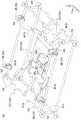
図1は、第1実施形態にかかるマルチコプター101の外観を示す斜視図であり、図2はマルチコプター101の外観を示す側面図である。[First Embodiment]
(Configuration overview)
FIG. 1 is a perspective view showing the appearance of the
マルチコプター101は複数のローターRを備えており、これらローターRは、4基の水平回転翼HR、および2基の垂直回転翼VRにより構成されている。水平回転翼HRおよび垂直回転翼VRは、互いに回転軸の配置方向が直交するように配置されている。4基の水平回転翼HRは水平に並べられており、左右および前後に2列に配置されている。2基の垂直回転翼VRは、その吸気側を前方に向けて左右に並べて配置されている。水平回転翼HRおよび垂直回転翼VRはいずれも、その周囲がダクト400によって覆われたダクテッドファンである。なお、本発明の「水平回転翼」とは、回転面が水平または略水平となるように配置された回転翼をいい、「垂直回転翼」とは回転面が鉛直または略鉛直となるように配置された回転翼をいう。 The
水平回転翼HRおよび垂直回転翼VRは、パイプ材で構成された側面視略L字形の枠体510に支持されている。枠体510にはさらに、回転体である6個のタイヤ243が支持されている。6個のタイヤ243はいずれも、駆動源であるモータ242を備えた駆動輪である。6個のタイヤ243は、その回転軸の軸線方向が、水平回転翼HRおよび垂直回転翼VRの回転軸の配置方向と直交する方向に向けられている。 The horizontal rotating blades HR and the vertical rotating blades VR are supported by a
6個のタイヤ243は、4基の水平回転翼HRを間に挟んでその左右に配置された天井面用タイヤHW、および2基の垂直回転翼VRを間に挟んでその左右に配置された垂直面用タイヤVWにより構成されている。天井面用タイヤHWは、そのタイヤ径方向における上端が、水平回転翼HRの回転面の位置よりも水平回転翼HRの吸気側(上方)にあり、さらに、水平回転翼HRが備えるダクト400の吸気側端部よりも吸気側(上方)に延出している。また、垂直面用タイヤVWは、そのタイヤ径方向における前方端部が、垂直回転翼VRの回転面の位置よりも垂直回転翼VRの吸気側(前方)にあり、さらに、垂直回転翼VRが備えるダクト400の吸気側端部よりも吸気側(前方)に延出している。なお、側面から見た枠体510の、その略L字形状の角部に配置されたタイヤ243は、天井面用タイヤHWおよび垂直面用タイヤVWを兼ねている。 The six
枠体510の後部には、マルチコプター101の制御装置などが収容されたケース体であるコントロールボックス590が配置されている。また、枠体510の後部には、着陸時における枠体510の後部を支持するパイプ材であるスタンド511が接続されている。また、枠体510の前面を構成するパイプ材のうち、その下辺を構成するパイプ材には、4基の水平回転翼HRの中央部を支持するT字形のパイプ材である補強部512が接続されている。 A
枠体510の前面を構成するパイプ材のうち、その上辺を構成するパイプ材には、カメラ300が固定されるカメラ台310が取り付けられている。カメラ台310には、その長手方向における両端部に、カメラ300を固定する固定部310a,310bが設けられている。前方を撮影するカメラ300は、カメラ台310の上側の固定部310aに固定される。上方を撮影するカメラ300は、カメラ台310の前側の固定部310bに固定される。これにより、撮影対象とカメラ300との適切な距離を確保することが可能とされている。なお、天井面用タイヤHWは、固定部310aに固定されるカメラ300よりも上方に延出しており、垂直面用タイヤVWは、固定部310bに固定されるカメラ300よりも前方に延出している。 A
(壁面走行動作)
マルチコプター101は、ローターRの回転面の位置よりもそのローターRの吸気側にタイヤ243の一部が延出している。そのため、ローターRの吸気側にある構造物Sに機体を接近させたときには、ローターRよりも先にタイヤ243が構造物Sに接触する。つまり、マルチコプター101は、構造物SとローターRとの衝突が物理的に生じ得ない構成とされており、これにより、機体を安全に構造物Sに接近させることが可能とされている。(Wall running operation)
In the
また、マルチコプター101は上記構成を備えていることにより、ローターRの吸気側に生じる負圧で機体を構造物Sの面に吸い付かせ、その状態でタイヤ243を駆動することにより、構造物Sと機体との間隔を一定に保ったまま構造物Sの面上を走行することが可能とされている。さらに、上でも述べたように、本実施形態のローターRは全てダクテッドファンであるため、ローターRの翼端に生じる渦流がダクト400により軸線方向の気流に整流され、ダクト400の吸気側の負圧が高められるとともに安定する。これにより、構造物Sに対してより強固に機体を吸い付かせることが可能とされている。 Further, since the
図3は、水平面および垂直面におけるマルチコプター101の壁面走行の様子を示す模式図である。本実施形態のマルチコプター101は、水平回転翼HRと垂直回転翼VRとを備え、さらに、これら水平回転翼HRおよび垂直回転翼VRのそれぞれに対して、その吸気側に延出した天井面用タイヤHWおよび垂直面用タイヤVWを備えていることにより、例えば橋桁の下面のような天井面HSだけでなく、ビルや橋脚の壁面などの垂直面VSに対しても機体を容易に吸い付かせることができる。これにより、図3に示すように、天井面HSから垂直面VSへの移動およびその逆方向の移動を連続的に行うことが可能とされている。 FIG. 3 is a schematic diagram showing the state of the wall traveling of the
また、マルチコプター101は、ローターRおよびタイヤ243が側面視略L字形の枠体510に配置されていることにより、水平回転翼HRを用いて天井面HSに機体を吸い付かせるときや、垂直回転翼VRを用いて垂直面VSに機体を吸い付かせるときに、他方のローターRがその妨げになることが防止されている。 Further, the
また、本実施形態のマルチコプター101は、天井面HSまたは垂直面VSにおいて、水平回転翼HRの左右に配置された個々の天井面用タイヤHW、または、垂直回転翼VRの左右に配置された個々の垂直面用タイヤVWの回転数や回転方向を制御することにより、機体の向きや進行方向を変更することができる。タイヤ243にステアリング機構を別途備えることなく、各タイヤ243の回転数や回転方向により構造物Sの面上における機体の向きを変更可能とすることにより、マルチコプター101はその機体構造が単純化されている。さらに、本構成によれば、例えば機体の前後の向きをその場で入れ替えるような動作も可能となり、構造物Sの面上をより柔軟かつ自由に移動することができる。 Further, the
(飛行機能)
図4はマルチコプター101の機能構成を示すブロック図である。マルチコプター101の飛行機能は、主に、フライトコントローラFC、回転翼である複数のローターR、ローターRごとに備えられたESC141(Electric Speed Controller)、およびこれらに電力を供給するバッテリー190により構成されている。以下、マルチコプター101の基本的な飛行機能について説明する。(Flight function)
FIG. 4 is a block diagram showing a functional configuration of the
各ローターRは、モータ142と、その出力軸に連結されたブレード143とにより構成されている。ESC141は、ローターRのモータ142に接続されており、フライトコントローラFCから指示された速度でモータ142を回転させる。 Each rotor R is composed of a
フライトコントローラFCは、オペレータ(送信器110)からの操縦信号を受信する受信器131と、受信器131が接続されたマイクロコントローラである制御装置120を備えている。制御装置120は、中央処理装置であるCPU121、ROMやRAMなどの記憶装置であるメモリ122、および、ESC141を介して各モータ142の回転数を制御するPWM(Pulse Width Modulation)コントローラ123を有している。 The flight controller FC includes a
フライトコントローラFCはさらに、飛行制御センサ群132およびGPS受信器133(以下、これらを総称して「センサ等」ともいう。)を備えており、これらは制御装置120に接続されている。本実施形態におけるマルチコプター101の飛行制御センサ群132には、3軸加速度センサ、3軸角速度センサ、気圧センサ(高度センサ)、地磁気センサ(方位センサ)などが含まれている。制御装置120は、これらセンサ等により、機体の傾きや回転のほか、飛行中の緯度経度、高度、および機首の方位角を含む自機の位置情報を取得可能とされている。 The flight controller FC further includes a flight
制御装置120のメモリ122には、マルチコプター101の飛行時における姿勢や基本的な飛行動作を制御するアルゴリズムが実装されたプログラムである飛行制御プログラムFCPが記憶されている。飛行制御プログラムFCPは、オペレータからの指示に従い、センサ等から取得した情報を基に、個々のローターRの回転数を調節し、機体の姿勢や位置の乱れを補正しながらマルチコプター101を飛行させる。 The
マルチコプター101の操縦は、オペレータが送信器110を用いて手動で行うほか、マルチコプター101の飛行経路や速度、高度などのパラメータである飛行計画FPを自律飛行プログラムAPPに予め登録しておき、マルチコプター101を目的地へ自律的に飛行させることも可能である(以下、このような自律飛行のことを「オートパイロット」という。)。 The operation of the
このように、本実施形態におけるマルチコプター101は高度な飛行制御機能を備えている。ただし、本発明における無人航空機はマルチコプター101の形態には限定されず、例えばセンサ等から一部のセンサが省略された機体や、オートパイロット機能を備えず手動操縦のみにより飛行可能な機体を用いることもできる。 Thus, the
(壁面走行機能)
マルチコプター101はさらに、オペレータ(送信器110)からの操縦信号を受信する受信器231と、受信器231が接続されたマイクロコントローラである制御装置220とを備えている。制御装置220は、中央処理装置であるCPU221、ROMやRAMなどの記憶装置であるメモリ222、並びに、ESC241を介して各モータ242およびタイヤ243の回転数を制御するPWMコントローラ223を有している。制御装置220のメモリ222には、構造物Sの面上における機体の走行動作を制御するプログラムである走行制御プログラムDCPが記憶されている。(Wall running function)
The
マルチコプター101の壁面走行機能は、上記飛行機能、および走行制御プログラムDCPにより実現されている。飛行制御プログラムFCPは、マルチコプター101が構造物Sの天井面HSまたは垂直面VSに到達した後は、これら天井面HSおよび垂直面VSに機体を吸い付かせることにのみ水平回転翼HRおよび垂直回転翼VRを駆動する。そして、走行制御プログラムDCPは、オペレータからの指示に従ってタイヤ243を駆動させ、構造物Sの面上でマルチコプター101を移動させる。 The wall traveling function of the
なお、本実施形態では、走行制御プログラムDCPは飛行制御プログラムFCPとは別体の制御装置220に配置されているが、制御装置120の処理能力に余裕があれば、走行制御プログラムDCPおよびPWMコントローラ223を制御装置120に配置して、制御装置220や受信器231の構成を省略することもできる。また、本実施形態のマルチコプター101では、構造物Sの面上におけるマルチコプター101の移動は、基本的にオペレータが手動で行うことを想定しているが、マルチコプター101の走行経路や速度などのパラメータを予め設定しておき、または構造物Sの面とマルチコプター101の状態を見ながらこれらパラメータを都度設定することにより、構造物Sの面上でマルチコプター101を自律的または半自律的に走行させる機能を実装してもよい。 In this embodiment, the travel control program DCP is arranged in the
[第2実施形態]
以下に、本発明の無人航空機の第2実施形態について図面を用いて説明する。以下の説明では、先の実施形態と同一または同様の機能を有する構成については、先の実施形態と同一の符号を付してその詳細な説明を省略する。[Second Embodiment]
Below, 2nd Embodiment of the unmanned aerial vehicle of this invention is described using drawing. In the following description, components having the same or similar functions as those of the previous embodiment are denoted by the same reference numerals as those of the previous embodiment, and detailed description thereof is omitted.
図5は第2実施形態にかかるマルチコプター102の外観を示す斜視図である。マルチコプター102はローターRとして4基の水平回転翼HRのみを備える機体である。これら水平回転翼HRの吸気側(上方)には、モータ242を備えるタイヤ243である4個の天井面用タイヤHWが配置されている。 FIG. 5 is a perspective view showing an appearance of the
マルチコプター102は、水平回転翼HRおよび天井面用タイヤHWを支持する枠体520を有している。枠体520は、パイプ材により構成された略直方体形状の枠体である外枠521と、連結パイプ522により外枠521の内側に支持された、同じくパイプ材からなる略矩形状の内枠523とを有している。内枠523にはマルチコプター102のコントロールボックス590およびカメラ300が支持されている。また、外枠521の各頂点に相当する部位には、駆動源を備えないタイヤ245が配置されている。 The
外枠521の前面(X軸方向における図5視左側の面)を構成するパイプ材は、その下辺を構成するパイプ材521bが、上辺を構成するパイプ材521aよりも水平方向外側に配置されている。これにより、外枠521の前面を垂直面VSに当接させたときに、枠体520とともに水平回転翼HRがその垂直面VS側に傾斜することとなる。そして、水平回転翼HRの推力のうち、垂直面VS側に向かう分力により、機体が垂直面VSに押し付けられる。これにより、マルチコプター102は、天井面HSにおける壁面走行が可能であるとともに、垂直面VSとの距離を安定して一定に保つことも可能とされている。 The pipe material constituting the front surface of the outer frame 521 (the surface on the left side in FIG. 5 in the X-axis direction) is such that the
[第3実施形態]
以下に、本発明の無人航空機の第3実施形態について図面を用いて説明する。以下の説明では、先の実施形態と同一または同様の機能を有する構成については、先の実施形態と同一の符号を付してその詳細な説明を省略する。[Third Embodiment]
Below, 3rd Embodiment of the unmanned aerial vehicle of this invention is described using drawing. In the following description, components having the same or similar functions as those of the previous embodiment are denoted by the same reference numerals as those of the previous embodiment, and detailed description thereof is omitted.
図6は、第3実施形態にかかるマルチコプター103を用いて、一般的な集合住宅のベランダに荷物Lを宅配する方法を示す模式図である。荷物Lはマルチコプター103の上部に固定されている。なお、以下に説明するマルチコプター103の特徴を除き、マルチコプター103の基本的な構成や機能はマルチコプター101と同様である。 FIG. 6 is a schematic diagram showing a method for delivering a package L to a veranda of a general apartment house using the
本実施形態のマルチコプター103は、GPS受信器133を用いて宅配先の集合住宅の所在地へと向かう。マルチコプター103は固定翼700を備えており、集合住宅への移動時には、垂直回転翼VRを水平方向への推力として利用する。 The
集合住宅の各戸のベランダには、予めLEDやBluetooth(登録商標) Low Energyビーコンなどの信号発信機Bが取り付けられている。マルチコプター103が集合住宅に十分に接近した後は、マルチコプター103は、撮影手段や近距離無線通信手段により信号発信機Bの信号を受信し、荷物Lの宛先である一戸のベランダを特定する。また、マルチコプター103は、ベランダの塀Fに機体を吸い付かせるときも、信号発信機Bの取り付け位置を基準として、機体を最適な位置に調節する。 A signal transmitter B such as LED or Bluetooth (registered trademark) Low Energy beacon is attached in advance to the veranda of each house of the apartment house. After the
図7は、ベランダの塀Fにアーム600で機体を係止する様子を示す模式側面図である。マルチコプター103は、垂直回転翼VRでベランダの塀Fに吸い付き、さらにアーム600をベランダの塀Fの上に伸ばして、アーム600の鉤部610を塀Fの背面に係合させる。そして垂直回転翼VRおよび水平回転翼HRを停止し、アーム600で機体を支持する。なお、鉤部610は、塀Fの厚み応じてその位置を調節することができる。住人が荷物Lを受け取ると、マルチコプター103は感圧センサなどによりそれを検知し、一定時間の待機の後、アーム600を塀Fから外し、ベランダを離れる。 FIG. 7 is a schematic side view showing a state in which the airframe is locked by the
マルチコプター103に荷物Lを載せ、集合住宅のベランダに荷物Lを宅配するときに、住人が荷物Lを受け取るまでベランダの塀Fに機体を吸い付かせておくことは、バッテリー効率の点から好ましくない。また、ローターRは鋭利であるため、ローターRを回しながら荷物Lを受け渡した場合、住人がけがをするおそれもある。マルチコプター103が鉤付きアーム600を備え、そのアーム600でベランダの塀Fに機体を係止することにより、ローターRを停止した状態で住人に荷物Lを受け渡すことができる。また、荷物の受け渡しに時間を要した場合でも、帰巣のための電力を確保しておくことができる。 From the viewpoint of battery efficiency, it is preferable to place the aircraft on the veranda wall F until the resident receives the package L when the package L is loaded on the
以上、本発明の実施の形態について説明したが、本発明は上記各実施の形態に限定されるものではなく、本発明の要旨を逸脱しない範囲で種々の改変が可能である。例えば、上記実施形態のマルチコプター101,102,103はいずれも複数のローターRを備えているが、本発明の無人航空機は、水平回転翼HRが一つだけの機体であってもよい。また、上記実施形態の水平回転翼HRおよび垂直回転翼VRは、互いに回転軸の配置方向が直交するように配置されているが、これらは常に直交配置されている必要はなく、天井面HSと垂直面VSの両方に吸い付きやすいように、回転軸を交差させて配置されていればよい。また、本発明の「回転体」としては、タイヤ273などの車輪だけではなく、クローラや履帯などとよばれる無限軌道を用いることもできる。
Although the embodiments of the present invention have been described above, the present invention is not limited to the above embodiments, and various modifications can be made without departing from the scope of the present invention. For example, although the
Claims (7)
Translated fromJapanese前記各回転翼の周囲を覆うダクトと、
駆動源を有する複数の回転体と、を備え、
前記各回転体は、その回転径方向における少なくとも一部が、前記ダクトの筒軸方向における吸気側端部の位置よりも該吸気側に延出しており、
前記ダクトの吸気側に生じる負圧で機体を構造物の面に吸い付かせ、その状態で前記複数の回転体を駆動することにより該面上を走行可能であることを特徴とする無人航空機。One or more rotor blades;
A duct covering the periphery of each rotor blade;
A plurality of rotating bodies having a drive source,
Each of the rotating bodies has at least a part thereof in the rotational radial direction extending to the intake side from the position of the intake side end in the cylindrical axis direction of the duct,
An unmanned aerial vehicle characterized in that the unmanned aerial vehicle can travel on a surface of the structure by attracting the airframe to the surface of the structure with negative pressure generated on the intake side of the duct and driving the plurality of rotating bodies in this state.
駆動源を有する複数の回転体と、を備え、
前記複数の回転翼は、回転軸の配置方向が交差する水平回転翼および垂直回転翼を有しており、
前記複数の回転体は、その回転径方向における少なくとも一部が、前記水平回転翼の回転面の位置よりも該水平回転翼の吸気側に延出した前記回転体と、前記垂直回転翼の回転面の位置よりも該垂直回転翼の吸気側に延出した前記回転体と、を有しており、
前記回転翼の吸気側に生じる負圧で機体を構造物の面に吸い付かせ、その状態で前記複数の回転体を駆動することにより該面上を走行可能であることを特徴とする無人航空機。A plurality of rotor blades,
A plurality of rotating bodies having a drive source,
The plurality of rotary blades have a horizontal rotary blade and a vertical rotary blade whose arrangement directions of the rotation axes intersect,
The plurality of rotators are configured such that at least a part of the rotator in the radial direction extends from the position of the rotating surface of the horizontal rotor to the intake side of the horizontal rotor, and the rotation of the vertical rotor The rotating body extending to the intake side of the vertical rotary blade from the position of the surface, and
An unmanned aerial vehicle capable of traveling on a surface of the structure by attracting the airframe to a surface of a structure with a negative pressure generated on an intake side of the rotor and driving the plurality of rotors in that state. .
前記枠体は、下辺を構成する前記パイプ材が、上辺を構成する前記パイプ材よりも水平方向外側に配置された側面を有していることを特徴とする請求項1に記載の無人航空機。The rotor blades and the plurality of rotors are supported by a frame body made of a pipe material,
2. The unmanned aerial vehicle according to claim 1, wherein the frame body has a side surface in which the pipe material constituting the lower side is disposed on the outer side in the horizontal direction than the pipe material constituting the upper side.
前記枠体は側面視略L字形に形成されていることを特徴とする請求項2に記載の無人航空機。The plurality of rotor blades and the plurality of rotors are supported by a frame body made of a pipe material,
The unmanned aerial vehicle according to claim 2, wherein the frame is formed in a substantially L shape in a side view.
水平飛行時には前記垂直回転翼を推力として用いることを特徴とする請求項2に記載の無人航空機。A fixed wing,
The unmanned aerial vehicle according to claim 2, wherein the vertical rotary wing is used as a thrust during horizontal flight.
前記アームを塀状の構造物の上に伸ばし、前記鉤部を該塀状の構造物の背面に係合させることにより、該アームで機体を支持可能であることを特徴とする請求項1に記載の無人航空機。It further comprises an arm with a buttock formed at the tip,
The aircraft can be supported by the arm by extending the arm over a bowl-like structure and engaging the hook with a back surface of the bowl-like structure. The unmanned aircraft described.
Applications Claiming Priority (5)
| Application Number | Priority Date | Filing Date | Title |
|---|---|---|---|
| JP2016083269 | 2016-04-19 | ||
| JP2016083269 | 2016-04-19 | ||
| JP2016091332 | 2016-04-28 | ||
| JP2016091332 | 2016-04-28 | ||
| PCT/JP2016/076151WO2017183219A1 (en) | 2016-04-19 | 2016-09-06 | Unmanned aerial vehicle |
Publications (2)
| Publication Number | Publication Date |
|---|---|
| JP6178949B1true JP6178949B1 (en) | 2017-08-09 |
| JPWO2017183219A1 JPWO2017183219A1 (en) | 2018-04-26 |
Family
ID=59559241
Family Applications (1)
| Application Number | Title | Priority Date | Filing Date |
|---|---|---|---|
| JP2017521607AActiveJP6178949B1 (en) | 2016-04-19 | 2016-09-06 | Unmanned aerial vehicle |
Country Status (1)
| Country | Link |
|---|---|
| JP (1) | JP6178949B1 (en) |
Cited By (13)
| Publication number | Priority date | Publication date | Assignee | Title |
|---|---|---|---|---|
| CN108100256A (en)* | 2017-12-13 | 2018-06-01 | 中国科学院重庆绿色智能技术研究院 | A kind of collapsible six rotors plant protection unmanned vehicle |
| WO2019046263A1 (en)* | 2017-08-28 | 2019-03-07 | Saudi Arabian Oil Company | Thruster based locomotion for perched unmanned aerial vehicles |
| CN109552615A (en)* | 2018-12-22 | 2019-04-02 | 酷黑科技(北京)有限公司 | A kind of stealthy unmanned plane and unmanned plane cluster job system |
| CN110065632A (en)* | 2019-03-28 | 2019-07-30 | 南京航空航天大学 | A kind of absorption type variant rotor craft |
| CN110871857A (en)* | 2019-11-15 | 2020-03-10 | 武汉理工大学 | Flying wall-climbing robot capable of automatically climbing wall and using method thereof |
| CN112829846A (en)* | 2021-03-03 | 2021-05-25 | 广东省科学院智能制造研究所 | A wall-climbing robot and its wall transition method |
| CN113148117A (en)* | 2021-06-01 | 2021-07-23 | 台州学院 | Jet-suction air foot rest of rotor unmanned aerial vehicle |
| CN113665698A (en)* | 2021-09-30 | 2021-11-19 | 南昌航空大学 | Wall surface detection system and detection method based on mechanical arm |
| CN113771979A (en)* | 2021-09-27 | 2021-12-10 | 北京理工大学 | Reverse thrust adsorption wall-climbing robot |
| JP2022055032A (en)* | 2020-09-28 | 2022-04-07 | 公益財団法人鉄道総合技術研究所 | Small unmanned aircraft |
| CN114537548A (en)* | 2022-03-04 | 2022-05-27 | 哈尔滨工业大学重庆研究院 | Adsorption type flying robot |
| CN116001938A (en)* | 2022-12-28 | 2023-04-25 | 北京理工大学 | Crawler-type double-rotor wall climbing robot |
| JP7534780B2 (en) | 2020-12-16 | 2024-08-15 | 株式会社プロドローン | Unmanned Aerial Vehicles |
Families Citing this family (1)
| Publication number | Priority date | Publication date | Assignee | Title |
|---|---|---|---|---|
| JP7658130B2 (en)* | 2021-03-24 | 2025-04-08 | 株式会社デンソー | Inspection Equipment |
Citations (3)
| Publication number | Priority date | Publication date | Assignee | Title |
|---|---|---|---|---|
| US8794564B2 (en)* | 2012-08-02 | 2014-08-05 | Neurosciences Research Foundation, Inc. | Vehicle capable of in-air and on-ground mobility |
| WO2016069169A1 (en)* | 2014-10-29 | 2016-05-06 | Qualcomm Incorporated | Unmanned aerial vehicle |
| WO2017051732A1 (en)* | 2015-09-25 | 2017-03-30 | 株式会社日本自動車部品総合研究所 | Flight device |
- 2016
- 2016-09-06JPJP2017521607Apatent/JP6178949B1/enactiveActive
Patent Citations (3)
| Publication number | Priority date | Publication date | Assignee | Title |
|---|---|---|---|---|
| US8794564B2 (en)* | 2012-08-02 | 2014-08-05 | Neurosciences Research Foundation, Inc. | Vehicle capable of in-air and on-ground mobility |
| WO2016069169A1 (en)* | 2014-10-29 | 2016-05-06 | Qualcomm Incorporated | Unmanned aerial vehicle |
| WO2017051732A1 (en)* | 2015-09-25 | 2017-03-30 | 株式会社日本自動車部品総合研究所 | Flight device |
Cited By (16)
| Publication number | Priority date | Publication date | Assignee | Title |
|---|---|---|---|---|
| WO2019046263A1 (en)* | 2017-08-28 | 2019-03-07 | Saudi Arabian Oil Company | Thruster based locomotion for perched unmanned aerial vehicles |
| US11077935B2 (en) | 2017-08-28 | 2021-08-03 | Saudi Arabian Oil Company | Thruster based locomotion for perched unmanned aerial vehicles |
| CN108100256A (en)* | 2017-12-13 | 2018-06-01 | 中国科学院重庆绿色智能技术研究院 | A kind of collapsible six rotors plant protection unmanned vehicle |
| CN109552615A (en)* | 2018-12-22 | 2019-04-02 | 酷黑科技(北京)有限公司 | A kind of stealthy unmanned plane and unmanned plane cluster job system |
| CN110065632A (en)* | 2019-03-28 | 2019-07-30 | 南京航空航天大学 | A kind of absorption type variant rotor craft |
| CN110871857A (en)* | 2019-11-15 | 2020-03-10 | 武汉理工大学 | Flying wall-climbing robot capable of automatically climbing wall and using method thereof |
| JP7365308B2 (en) | 2020-09-28 | 2023-10-19 | 公益財団法人鉄道総合技術研究所 | small unmanned aircraft |
| JP2022055032A (en)* | 2020-09-28 | 2022-04-07 | 公益財団法人鉄道総合技術研究所 | Small unmanned aircraft |
| JP7534780B2 (en) | 2020-12-16 | 2024-08-15 | 株式会社プロドローン | Unmanned Aerial Vehicles |
| CN112829846A (en)* | 2021-03-03 | 2021-05-25 | 广东省科学院智能制造研究所 | A wall-climbing robot and its wall transition method |
| CN112829846B (en)* | 2021-03-03 | 2024-01-30 | 广东省科学院智能制造研究所 | Wall climbing robot and wall transition method thereof |
| CN113148117A (en)* | 2021-06-01 | 2021-07-23 | 台州学院 | Jet-suction air foot rest of rotor unmanned aerial vehicle |
| CN113771979A (en)* | 2021-09-27 | 2021-12-10 | 北京理工大学 | Reverse thrust adsorption wall-climbing robot |
| CN113665698A (en)* | 2021-09-30 | 2021-11-19 | 南昌航空大学 | Wall surface detection system and detection method based on mechanical arm |
| CN114537548A (en)* | 2022-03-04 | 2022-05-27 | 哈尔滨工业大学重庆研究院 | Adsorption type flying robot |
| CN116001938A (en)* | 2022-12-28 | 2023-04-25 | 北京理工大学 | Crawler-type double-rotor wall climbing robot |
Also Published As
| Publication number | Publication date |
|---|---|
| JPWO2017183219A1 (en) | 2018-04-26 |
Similar Documents
| Publication | Publication Date | Title |
|---|---|---|
| JP6178949B1 (en) | Unmanned aerial vehicle | |
| WO2017183219A1 (en) | Unmanned aerial vehicle | |
| US11591083B2 (en) | Spherical VTOL aerial vehicle | |
| AU2019257690B2 (en) | Counter-rotating propellers for aerial vehicle | |
| JP7374517B2 (en) | Unmanned aerial vehicle with crash-resistant propulsion and controller | |
| KR101827308B1 (en) | A multicopter type smart drone using tilt rotor | |
| KR100812756B1 (en) | Quadcopter with easy yawing control | |
| CN107531325A (en) | Unmanned vehicle | |
| JP7089735B2 (en) | Unmanned aerial vehicle | |
| JP2018144627A (en) | Pilotless aircraft | |
| JP6592680B1 (en) | Unmanned aerial vehicle | |
| WO2016163482A1 (en) | Mobile unit | |
| JP2018134908A (en) | Unmanned aircraft | |
| KR102245397B1 (en) | Multi rotor unmanned aerial vehicle | |
| JP2017074868A (en) | Rotorcraft | |
| JP6561272B1 (en) | Rotorcraft | |
| JP2018090095A (en) | Unmanned flight device, shipment transporting method and program | |
| JP6661136B1 (en) | Unmanned aerial vehicle | |
| US20220274701A1 (en) | Aerial vehicle and flying method of aerial vehicle | |
| Cetinsoy | Design and simulation of a holonomic quadrotor UAV with sub-rotor control surfaces | |
| Watanabe et al. | Attitude control of a camera mounted-type tethered quadrotor for infrastructure inspection | |
| Cai et al. | QuadRotary: Design and Control of In-Flight Transition Between Quadcopter and Rotary-Wing | |
| CN109533331A (en) | Miniature drone | |
| Noda et al. | Mechanism and control of four rotor flying robot | |
| NL1040979B1 (en) | Air vehicle. |
Legal Events
| Date | Code | Title | Description |
|---|---|---|---|
| A975 | Report on accelerated examination | Free format text:JAPANESE INTERMEDIATE CODE: A971005 Effective date:20170607 | |
| TRDD | Decision of grant or rejection written | ||
| A01 | Written decision to grant a patent or to grant a registration (utility model) | Free format text:JAPANESE INTERMEDIATE CODE: A01 Effective date:20170620 | |
| A61 | First payment of annual fees (during grant procedure) | Free format text:JAPANESE INTERMEDIATE CODE: A61 Effective date:20170714 | |
| R150 | Certificate of patent or registration of utility model | Ref document number:6178949 Country of ref document:JP Free format text:JAPANESE INTERMEDIATE CODE: R150 | |
| S531 | Written request for registration of change of domicile | Free format text:JAPANESE INTERMEDIATE CODE: R313531 | |
| R350 | Written notification of registration of transfer | Free format text:JAPANESE INTERMEDIATE CODE: R350 | |
| R250 | Receipt of annual fees | Free format text:JAPANESE INTERMEDIATE CODE: R250 | |
| R250 | Receipt of annual fees | Free format text:JAPANESE INTERMEDIATE CODE: R250 | |
| S533 | Written request for registration of change of name | Free format text:JAPANESE INTERMEDIATE CODE: R313533 | |
| R350 | Written notification of registration of transfer | Free format text:JAPANESE INTERMEDIATE CODE: R350 |