JP6178796B2 - LIGHTING DEVICE AND ROAD LIGHTING EQUIPMENT HAVING THE LIGHTING DEVICE - Google Patents
LIGHTING DEVICE AND ROAD LIGHTING EQUIPMENT HAVING THE LIGHTING DEVICEDownload PDFInfo
- Publication number
- JP6178796B2 JP6178796B2JP2014541774AJP2014541774AJP6178796B2JP 6178796 B2JP6178796 B2JP 6178796B2JP 2014541774 AJP2014541774 AJP 2014541774AJP 2014541774 AJP2014541774 AJP 2014541774AJP 6178796 B2JP6178796 B2JP 6178796B2
- Authority
- JP
- Japan
- Prior art keywords
- lighting device
- axis
- road
- lighting
- parabolic curve
- Prior art date
- Legal status (The legal status is an assumption and is not a legal conclusion. Google has not performed a legal analysis and makes no representation as to the accuracy of the status listed.)
- Expired - Fee Related
Links
- 230000003287optical effectEffects0.000claimsdescription18
- 238000005286illuminationMethods0.000claimsdescription17
- 238000000034methodMethods0.000claimsdescription9
- 150000001875compoundsChemical class0.000claimsdescription5
- 230000004313glareEffects0.000description6
- 230000000694effectsEffects0.000description5
- 230000004907fluxEffects0.000description4
- 230000002411adverseEffects0.000description3
- 239000000919ceramicSubstances0.000description3
- 238000010586diagramMethods0.000description3
- 101100067993Saccharomyces cerevisiae (strain ATCC 204508 / S288c) ASC1 geneProteins0.000description2
- 101100067991Schizosaccharomyces pombe (strain 972 / ATCC 24843) rkp1 geneProteins0.000description2
- 229910052736halogenInorganic materials0.000description2
- 150000002367halogensChemical class0.000description2
- 238000009434installationMethods0.000description2
- 238000012423maintenanceMethods0.000description2
- 239000002184metalSubstances0.000description2
- 101100067989Neurospora crassa (strain ATCC 24698 / 74-OR23-1A / CBS 708.71 / DSM 1257 / FGSC 987) cpc-2 geneProteins0.000description1
- 206010052143Ocular discomfortDiseases0.000description1
- 230000006872improvementEffects0.000description1
- 229910001507metal halideInorganic materials0.000description1
- 150000005309metal halidesChemical class0.000description1
- 238000012986modificationMethods0.000description1
- 230000004048modificationEffects0.000description1
- 230000002265preventionEffects0.000description1
Images


Classifications
- F—MECHANICAL ENGINEERING; LIGHTING; HEATING; WEAPONS; BLASTING
- F21—LIGHTING
- F21S—NON-PORTABLE LIGHTING DEVICES; SYSTEMS THEREOF; VEHICLE LIGHTING DEVICES SPECIALLY ADAPTED FOR VEHICLE EXTERIORS
- F21S8/00—Lighting devices intended for fixed installation
- F21S8/08—Lighting devices intended for fixed installation with a standard
- F—MECHANICAL ENGINEERING; LIGHTING; HEATING; WEAPONS; BLASTING
- F21—LIGHTING
- F21V—FUNCTIONAL FEATURES OR DETAILS OF LIGHTING DEVICES OR SYSTEMS THEREOF; STRUCTURAL COMBINATIONS OF LIGHTING DEVICES WITH OTHER ARTICLES, NOT OTHERWISE PROVIDED FOR
- F21V7/00—Reflectors for light sources
- F21V7/04—Optical design
- F21V7/06—Optical design with parabolic curvature
- F—MECHANICAL ENGINEERING; LIGHTING; HEATING; WEAPONS; BLASTING
- F21—LIGHTING
- F21S—NON-PORTABLE LIGHTING DEVICES; SYSTEMS THEREOF; VEHICLE LIGHTING DEVICES SPECIALLY ADAPTED FOR VEHICLE EXTERIORS
- F21S8/00—Lighting devices intended for fixed installation
- F21S8/08—Lighting devices intended for fixed installation with a standard
- F21S8/081—Lighting devices intended for fixed installation with a standard of low-built type, e.g. landscape light
- F—MECHANICAL ENGINEERING; LIGHTING; HEATING; WEAPONS; BLASTING
- F21—LIGHTING
- F21S—NON-PORTABLE LIGHTING DEVICES; SYSTEMS THEREOF; VEHICLE LIGHTING DEVICES SPECIALLY ADAPTED FOR VEHICLE EXTERIORS
- F21S8/00—Lighting devices intended for fixed installation
- F21S8/08—Lighting devices intended for fixed installation with a standard
- F21S8/085—Lighting devices intended for fixed installation with a standard of high-built type, e.g. street light
- F21S8/086—Lighting devices intended for fixed installation with a standard of high-built type, e.g. street light with lighting device attached sideways of the standard, e.g. for roads and highways
- F—MECHANICAL ENGINEERING; LIGHTING; HEATING; WEAPONS; BLASTING
- F21—LIGHTING
- F21V—FUNCTIONAL FEATURES OR DETAILS OF LIGHTING DEVICES OR SYSTEMS THEREOF; STRUCTURAL COMBINATIONS OF LIGHTING DEVICES WITH OTHER ARTICLES, NOT OTHERWISE PROVIDED FOR
- F21V7/00—Reflectors for light sources
- F21V7/04—Optical design
- F21V7/09—Optical design with a combination of different curvatures
- F—MECHANICAL ENGINEERING; LIGHTING; HEATING; WEAPONS; BLASTING
- F21—LIGHTING
- F21Y—INDEXING SCHEME ASSOCIATED WITH SUBCLASSES F21K, F21L, F21S and F21V, RELATING TO THE FORM OR THE KIND OF THE LIGHT SOURCES OR OF THE COLOUR OF THE LIGHT EMITTED
- F21Y2115/00—Light-generating elements of semiconductor light sources
- F21Y2115/10—Light-emitting diodes [LED]
- Y—GENERAL TAGGING OF NEW TECHNOLOGICAL DEVELOPMENTS; GENERAL TAGGING OF CROSS-SECTIONAL TECHNOLOGIES SPANNING OVER SEVERAL SECTIONS OF THE IPC; TECHNICAL SUBJECTS COVERED BY FORMER USPC CROSS-REFERENCE ART COLLECTIONS [XRACs] AND DIGESTS
- Y02—TECHNOLOGIES OR APPLICATIONS FOR MITIGATION OR ADAPTATION AGAINST CLIMATE CHANGE
- Y02B—CLIMATE CHANGE MITIGATION TECHNOLOGIES RELATED TO BUILDINGS, e.g. HOUSING, HOUSE APPLIANCES OR RELATED END-USER APPLICATIONS
- Y02B20/00—Energy efficient lighting technologies, e.g. halogen lamps or gas discharge lamps
- Y02B20/72—Energy efficient lighting technologies, e.g. halogen lamps or gas discharge lamps in street lighting
- Y—GENERAL TAGGING OF NEW TECHNOLOGICAL DEVELOPMENTS; GENERAL TAGGING OF CROSS-SECTIONAL TECHNOLOGIES SPANNING OVER SEVERAL SECTIONS OF THE IPC; TECHNICAL SUBJECTS COVERED BY FORMER USPC CROSS-REFERENCE ART COLLECTIONS [XRACs] AND DIGESTS
- Y10—TECHNICAL SUBJECTS COVERED BY FORMER USPC
- Y10T—TECHNICAL SUBJECTS COVERED BY FORMER US CLASSIFICATION
- Y10T29/00—Metal working
- Y10T29/49—Method of mechanical manufacture
- Y10T29/49826—Assembling or joining
Landscapes
- Engineering & Computer Science (AREA)
- General Engineering & Computer Science (AREA)
- Non-Portable Lighting Devices Or Systems Thereof (AREA)
Description
Translated fromJapanese本発明は、道路照明に関し、詳細には、照明装置、及び該照明装置を備えた道路照明器具に関する。 The present invention relates to road lighting, and more particularly, to a lighting device and a road lighting apparatus including the lighting device.
都市化の速度に起因して、より多くの陸橋又は高架交差路が、元々道路である場所の上に建設されている。そのような場所において使用される照明により満たされるべき様々な特別の特性又は要件が存在する。そのような特性又は要件として、取付及び維持の容易さ、建造物の全体的な美的デザインとの調和、防振に関する考慮などがある。同時に、グレア(glare)がないこと、輝度の均一性、平均的な輝度レベルなど、一般的な道路照明要件が満たされるべきである。 Due to the speed of urbanization, more overpasses or overpasses are being built on places that were originally roads. There are various special characteristics or requirements that must be met by the lighting used in such locations. Such characteristics or requirements include ease of installation and maintenance, harmony with the overall aesthetic design of the building, and anti-vibration considerations. At the same time, general road lighting requirements such as absence of glare, brightness uniformity, average brightness level should be met.
高いマストの照明、及び側壁に埋め込まれた照明器具を含め、陸橋及び高架交差路の利用に際し、いくつかの照明ソリューション(lighting solution)が利用可能である。 Several lighting solutions are available for the use of overpasses and elevated crossings, including high mast lighting and luminaires embedded in the sidewalls.
高架交差路を明るくするために、これまで高いマストの照明が広く一般に使用されているが、高いマストの照明は、いくつかのデメリットを有する。このようなデメリットとして、極度の高光束出力によって生じる強力なグレア、難しく費用のかかる取付及び維持、高架交差路による影に起因する地面の避けられない死角、高架交差路の適用に際した低い利用率などがある。さらに、道路脇の繁茂する木々が、マストにおける道路照明器具からの光を遮り、全体的な輝度レベル及び輝度の均一性に悪影響を与え、それにより、運転の安全性が低下する、という運転手及び道路照明管理者からの不満がある。 Up to now, high mast lighting has been widely used to brighten the elevated crossroads, but high mast lighting has several disadvantages. These disadvantages include strong glare caused by extremely high luminous flux output, difficult and costly installation and maintenance, unavoidable blind spots on the ground due to shadows from elevated intersections, and low utilization rates when applying elevated intersections and so on. In addition, the trees on the side of the road block the light from the road lighting fixtures on the mast, adversely affecting the overall brightness level and brightness uniformity, thereby reducing driving safety. And there are complaints from road lighting managers.
側壁に埋め込まれた照明器具が、別の照明オプション(lighting option)として、一般的に使用されている。側壁に埋め込まれた照明器具は、一般に、光源として蛍光灯を使用し、低い取付高さで側壁のフェンスに埋め込まれている。側壁に埋め込まれた照明器具も、いくつかのデメリットを有する。このようなデメリットとして、運転の安全性に関する照度レベルが不十分であること、及び照度の均一性が悪いことなどがある。 Luminaires embedded in the side walls are commonly used as another lighting option. The luminaire embedded in the side wall generally uses a fluorescent lamp as a light source, and is embedded in the side wall fence at a low mounting height. Lighting fixtures embedded in the side walls also have some disadvantages. Such disadvantages include an insufficient illuminance level related to driving safety and poor uniformity of illuminance.
最近、Thorn Lighting社が、Orusという商標名の低高度型取付照明器具(low-height mounted luminaire)を発売した。これは、出入道路又は橋に対して、グレアを防止する照明ソリューションを提供するよう主張されている。この照明器具は、光源としてセラミック金属ハロゲンランプ(ceramic metal halide lamp)を使用し、その光学的構造は、主に、円筒形状の反射鏡(reflector)から成っており、これは、道路表面に均一な照度を実現するよう主張されている。しかしながら、本発明の発明者らは、このような照明器具の次のようなデメリットを発見した。 Recently, Thorn Lighting has released a low-height mounted luminaire under the trade name Orus. This is claimed to provide lighting solutions for glare prevention for access roads or bridges. This luminaire uses a ceramic metal halide lamp as the light source, and its optical structure mainly consists of a cylindrical reflector, which is uniform on the road surface It is insisted to achieve a good illuminance. However, the inventors of the present invention have discovered the following disadvantages of such a lighting fixture.
光源として、セラミック金属ハロゲンランプは、サイズ及び形状が大きいため、光学的設計上、光強度及び/又は配光を制御することは難しい。さらに、発光面が非常にまぶしい。そのため、照明器具から自動車の運転手への直接的な強力な光放射は避けられず、これが、運転手の目に、ちらつきなどの視覚的不快感を生じさせ、したがって、安全性の問題を引き起こす。 As a light source, a ceramic metal halogen lamp has a large size and shape, and therefore it is difficult to control light intensity and / or light distribution in terms of optical design. Furthermore, the light emitting surface is very dazzling. Therefore, direct strong light emission from the luminaire to the car driver is unavoidable, which causes visual discomfort such as flickering in the driver's eyes and thus causes safety issues .
現実に配置される場合において、このような照明器具は、満足するレベルの輝度の均一性を道路表面に提供することができない。 In real-world arrangements, such luminaires cannot provide a satisfactory level of brightness uniformity on the road surface.
さらに、このような照明器具の全体は、サイズがかなり大きく、側壁のフェンスから突出し、歩行者及び/又は通過する車に悪影響を及ぼす。 Furthermore, the whole of such a luminaire is quite large in size and protrudes from the side wall fence, adversely affecting pedestrians and / or passing cars.
本発明は、現在利用可能な道路照明器具に対する改良である。 The present invention is an improvement over currently available road lighting fixtures.
グレアによる悪影響を効果的に低減又は排除することができる道路照明器具を提供することは、有用であろう。道路表面における輝度の均一性を満たすことを実現することができる道路照明器具を提供することは、さらに有用であろう。道路の木々により引き起こされる影による悪影響を低減又は排除することができる道路照明器具を提供することは、有用であろう。上述の効果を実現するよう、道路照明器具のための適切な光学的構造及び/又は機械的構造を提供することも望ましい。 It would be useful to provide a road lighting fixture that can effectively reduce or eliminate the negative effects of glare. It would be further useful to provide a road luminaire that can be achieved to meet brightness uniformity on the road surface. It would be useful to provide a road luminaire that can reduce or eliminate the negative effects of shadows caused by road trees. It would also be desirable to provide suitable optical and / or mechanical structures for road lighting equipment to achieve the effects described above.
こうした問題の1以上により良く対処するために、本発明の第1の側面において、道路照明器具用の照明装置が提供される。本照明装置は、反射鏡を備える。反射鏡は、第1の軸の周りに所定の角度だけ放物曲線(parabolic curve)を回転することにより形成された反射面を有する。放物曲線は、頂点(vertex)において開口を有する。第1の軸は、放物曲線と同一平面にあり、放物曲線の対称軸と実質的に垂直であり、放物曲線の開口に、又は開口の外側に位置する。本照明装置は、LED光源をさらに備える。LED光源は、反射面の入口(entry)に配置される。入口は、放物曲線の開口に対応する。すなわち、所定の角度だけ放物曲線を回転して反射面を形成する場合において、放物曲線の開口は、反射面の入口を形成する。 In order to better address one or more of these problems, in a first aspect of the present invention, a lighting device for a road lighting fixture is provided. The illumination device includes a reflecting mirror. The reflector has a reflecting surface formed by rotating a parabolic curve about a first axis by a predetermined angle. The parabolic curve has an opening at the vertex. The first axis is coplanar with the parabolic curve, is substantially perpendicular to the axis of symmetry of the parabolic curve, and is located at or outside the opening of the parabolic curve. The illumination device further includes an LED light source. The LED light source is disposed at the entry of the reflecting surface. The inlet corresponds to the opening of the parabolic curve. That is, when the reflecting surface is formed by rotating the parabolic curve by a predetermined angle, the opening of the parabolic curve forms the entrance of the reflecting surface.
このような反射面により、光は、所定の角度の範囲内にある第1の軸を含む任意の平面において、同様に制御することができる。というのは、反射面と第1の軸を含む任意の平面との交線が、同じ放物曲線であるからである。さらに、光源は、放物曲線の頂点に隣接して配置されるので、所定の角度の範囲内にある回転方向に沿った任意の位置で、ほとんど同一の光制御を実現することができる。 With such a reflective surface, the light can be similarly controlled in any plane including the first axis within a predetermined angle range. This is because the intersection line between the reflecting surface and an arbitrary plane including the first axis is the same parabolic curve. Furthermore, since the light source is disposed adjacent to the apex of the parabolic curve, almost the same light control can be realized at an arbitrary position along the rotation direction within a predetermined angle range.
さらに、第1の軸を含む任意の平面における光分布は、状況に応じて放物曲線を設計することにより、望むように制御することができる。例えば、第1の軸に沿った出力ビームの幅は、放物曲線の最大出口角(maximum exit angle)によって決まる。 Furthermore, the light distribution in any plane including the first axis can be controlled as desired by designing a parabolic curve according to the situation. For example, the width of the output beam along the first axis is determined by the maximum exit angle of the parabolic curve.
放物曲線は、放物線の任意のカーブ、又は放物線のようなカーブを指す。好ましくは、放物曲線は、1以上の円錐曲線セグメント(conic curve segment)を含む。円錐曲線セグメントは、放物線、双曲線、円、楕円などのセグメントであってよい。一実施形態では、放物曲線は、いわゆる複合放物集光器型曲線(CPC:Compound Parabolic Concentrator)である。 A parabola curve refers to any curve of a parabola or a parabola-like curve. Preferably, the parabolic curve includes one or more conic curve segments. A conic segment may be a parabola, hyperbola, circle, ellipse, or other segment. In one embodiment, the parabolic curve is a so-called compound parabolic concentrator (CPC).
一実施形態に従うと、所定の角度は、[90°,180°]の範囲内である。所定の角度が大きいほど、同一の光制御を実現することができる範囲が広くなる。一実施形態において、所定の角度は、180°である。 According to one embodiment, the predetermined angle is in the range [90 °, 180 °]. The larger the predetermined angle, the wider the range in which the same light control can be realized. In one embodiment, the predetermined angle is 180 °.
一実施形態に従うと、放物曲線の最大出口角は、5°内である。放物曲線の最大出口角は、放物曲線の対称軸に関して放物曲線の頂点に配置された光源からの光の最大出口角を指す。 According to one embodiment, the maximum exit angle of the parabolic curve is within 5 °. The maximum exit angle of a parabolic curve refers to the maximum exit angle of light from a light source located at the apex of the parabolic curve with respect to the axis of symmetry of the parabolic curve.
このようにして、第1の軸に沿った出力ビームの幅は、比較的小さくなるよう制御することができる。すなわち、出力ビームは、良好な指向性を実現する。 In this way, the width of the output beam along the first axis can be controlled to be relatively small. That is, the output beam realizes good directivity.
SON、蛍光灯、セラミック金属ハロゲンランプなどの光源と比較すると、LED光源は、サイズが小さく、長寿命を有する。 Compared with light sources such as SON, fluorescent lamps, and ceramic metal halogen lamps, LED light sources are small in size and have a long life.
LED光源の小さなサイズに起因して、反射鏡のサイズが小さい場合でも、LED光源は、反射面の入口に配置することができる。上述したように、LED光源が、反射面の入口に配置される場合、すなわち、放物曲線の頂点に配置される場合、所定の角度の範囲内にある回転方向に沿った任意の位置で、ほとんど同一の光制御を実現することができる。したがって、LED光源が良好な照度の均一性を提供する限り、光モジュールの出力ビームは、所定の角度の範囲内にある回転方向に沿って、良好な照度の均一性を有する。さらに、光源の輝く発光面は、発光面の小さなサイズに起因して、反射鏡内にうまく隠すことができ、それにより、グレアによる悪影響を低減することができる。 Due to the small size of the LED light source, the LED light source can be placed at the entrance of the reflecting surface even when the size of the reflector is small. As described above, when the LED light source is disposed at the entrance of the reflection surface, that is, when disposed at the apex of the parabolic curve, at an arbitrary position along the rotation direction within a predetermined angle range, Almost the same light control can be realized. Therefore, as long as the LED light source provides good illuminance uniformity, the output beam of the optical module has good illuminance uniformity along the direction of rotation within a predetermined angle range. In addition, the luminescent surface of the light source can be well hidden in the reflector due to the small size of the luminescent surface, thereby reducing the negative effects of glare.
一実施形態において、LED光源は、複数チップLEDを含む。単一チップLEDと比較すると、複数チップLEDは、高光束を実現することができる。それにより、照明装置は、運転の安全性のために、十分な輝度強度を提供することができる。 In one embodiment, the LED light source includes a multi-chip LED. Compared to single-chip LEDs, multi-chip LEDs can achieve high luminous flux. Thereby, the lighting device can provide sufficient luminance intensity for driving safety.
一実施形態において、LED光源は、複数のLEDモジュールを含む。したがって、1つのモジュールの故障が、照明装置全体の故障をもたらさないので、照明装置は、堅牢である。 In one embodiment, the LED light source includes a plurality of LED modules. Thus, the lighting device is robust because a failure of one module does not result in a failure of the entire lighting device.
別の実施形態に従うと、本照明装置は、反射鏡及びLED光源を保持するための保持ユニットと、ベース(base)とをさらに備える。保持ユニットは、保持ユニットが第2の軸の周りを回転可能なように、ベースに対して回転可能に接続され、第2の軸は、照明装置により生成されるビームの光軸、及び第1の軸の両方に垂直である。 According to another embodiment, the lighting device further comprises a holding unit for holding the reflector and the LED light source, and a base. The holding unit is rotatably connected to the base such that the holding unit can rotate about the second axis, the second axis being the optical axis of the beam generated by the illumination device, and the first Perpendicular to both axes.
このように、第2の軸の周りに保持ユニットを回転させることにより、照明装置により生成されるビームの光軸の方向は、ベースに対して調整可能である。 Thus, by rotating the holding unit around the second axis, the direction of the optical axis of the beam generated by the illumination device can be adjusted with respect to the base.
本発明の第2の側面において、道路照明器具が提供される。本道路照明器具は、道路に沿って取り付けられる支持物体(support)と、前述の照明装置であって、照明装置の第2の軸が道路の路肩と平行になるように、支持物体に取り付けられる照明装置とを備える。第2の軸は、照明装置により生成されるビームの光軸、及び第1の軸の両方に垂直である。 In a second aspect of the invention, a road lighting fixture is provided. The road luminaire is a support object that is attached along the road and the above-described illumination device, and is attached to the support object so that the second axis of the illumination device is parallel to the shoulder of the road. And a lighting device. The second axis is perpendicular to both the optical axis of the beam produced by the illumination device and the first axis.
上述したように、照明装置は、回転方向に沿って、良好な照度の均一性を提供することができる。すなわち、照明装置は、第2の軸に沿って、良好な照度の均一性を提供することができる。照明装置は、第2の軸が道路の路肩と平行になるように取り付けられるので、道路照明器具は、道路の路肩に沿って、良好な照度の均一性を提供することができる。それにより、大きな幅にわたって、道路表面に良好な照度の均一性を提供することができる。 As described above, the lighting device can provide good illuminance uniformity along the rotation direction. That is, the lighting device can provide good illuminance uniformity along the second axis. Since the lighting device is mounted so that the second axis is parallel to the road shoulder, the road lighting device can provide good illuminance uniformity along the road shoulder. Thereby, good illuminance uniformity can be provided on the road surface over a large width.
一実施形態において、照明装置は、道路の表面から所定の高さに取り付けられ、所定の高さは、1.2m以下である。好ましくは、所定の高さは、おおよそ1.0mである。 In one embodiment, the lighting device is mounted at a predetermined height from the road surface, and the predetermined height is 1.2 m or less. Preferably, the predetermined height is approximately 1.0 m.
このように、光源は、運転手の目の通常の高さよりも低い位置に取り付けられる。さらに、照明装置が、照明装置により生成されるビームの光軸が水平方向上方を延びて向かわないように取り付けられる限り、運転手の視線の下に、光をうまく制御することができる。したがって、直接的なグレアによる悪影響を排除することができる。 Thus, the light source is mounted at a position lower than the normal height of the driver's eyes. Furthermore, as long as the illuminating device is mounted so that the optical axis of the beam generated by the illuminating device does not extend upward in the horizontal direction, the light can be well controlled under the driver's line of sight. Therefore, adverse effects due to direct glare can be eliminated.
別の実施形態において、照明装置は、照明装置により生成されるビームの光軸が道路の中央に向かうように、取り付けられる。したがって、道路表面を効果的に照らすことができる。 In another embodiment, the lighting device is mounted such that the optical axis of the beam generated by the lighting device is toward the center of the road. Therefore, the road surface can be effectively illuminated.
本発明の第3の側面において、上述した照明装置を取り付ける方法が提供される。本方法は、照明装置の第2の軸が道路の路肩と平行になるように、道路の脇に照明装置を取り付けるステップを含む。第2の軸は、照明装置により生成されるビームの光軸、及び第1の軸の両方に垂直である。 In a third aspect of the present invention, a method for attaching the lighting device described above is provided. The method includes attaching the lighting device to the side of the road such that the second axis of the lighting device is parallel to the road shoulder. The second axis is perpendicular to both the optical axis of the beam produced by the illumination device and the first axis.
一実施形態において、本方法は、道路の表面から1.2m以下である高さに、照明装置を取り付けるステップをさらに含む。好ましくは、照明装置は、道路の表面からおおよそ1.0mの高さに取り付けられる。 In one embodiment, the method further includes attaching the lighting device to a height that is no greater than 1.2 meters from the surface of the road. Preferably, the lighting device is mounted at a height of approximately 1.0 m from the road surface.
別の実施形態において、本方法は、照明装置により生成されるビームの光軸を道路の中央に向けるステップをさらに含む。 In another embodiment, the method further comprises directing the optical axis of the beam generated by the lighting device to the center of the road.
別の実施形態において、本方法は、照明装置を道路の側壁のフェンスに取り付けるステップをさらに含む。 In another embodiment, the method further comprises the step of attaching the lighting device to a fence on the side wall of the road.
本発明は、請求項中に記載された特徴の全ての可能な組合せに関連することに留意されたい。 It should be noted that the invention relates to all possible combinations of the features recited in the claims.
本発明の他の特徴、目的、及び効果は、添付の図面と併せて検討される非限定的な例示的実施形態の以下の詳細な説明から明らかになるであろう。 Other features, objects, and advantages of the present invention will become apparent from the following detailed description of non-limiting exemplary embodiments considered in conjunction with the accompanying drawings.
同一の又は類似する参照符号は、同一の又は類似する装置(モジュール)を示す。 The same or similar reference numerals indicate the same or similar apparatus (module).
添付の図面を参照しながら、本発明の詳細な説明を以下で提供する。 A detailed description of the present invention is provided below with reference to the accompanying drawings.
図1は、本発明の一実施形態に従った、反射鏡の反射面のベースカーブ(base curve)の図を示している。 FIG. 1 shows a diagram of a base curve of a reflecting surface of a reflector according to one embodiment of the present invention.
本発明の一実施形態に従うと、道路照明器具用の照明装置が提供される。この照明装置は、第1の軸yの周りに所定の角度だけベースカーブを回転することにより形成された反射面を有する反射鏡を備える。このベースカーブは、図1に示される放物曲線1である。 According to one embodiment of the present invention, a lighting device for a road lighting fixture is provided. This illuminating device includes a reflecting mirror having a reflecting surface formed by rotating a base curve about a first axis y by a predetermined angle. This base curve is the parabolic curve 1 shown in FIG.
図1を参照すると、放物曲線1は、開口102に加え、その頂点において、開口101を有する。一般に、開口101は、開口102よりも小さい。以降、頂点における開口101を、入口開口(entry aperture)と呼び、開口102を、出口開口(exit aperture)と呼び、角度θmaxを、放物曲線1の最大出口角と呼ぶ。Referring to FIG. 1, the parabolic curve 1 has an
第1の軸yは、放物曲線1と同一平面にある、すなわち、放物曲線1を含む同一の平面に位置する。第1の軸yは、放物曲線1の対称軸である軸xと実質的に垂直である。さらに、第1の軸yは、開口101に、又は開口101の外側に位置する。一例では、第1の軸yは、図1に示されるように、開口101に正確に位置することができる。別の例では、第1の軸yは、開口101の外側に位置してもよい、すなわち、図1において開口101の左側に位置してもよい。 The first axis y is in the same plane as the parabolic curve 1, that is, is located in the same plane including the parabolic curve 1. The first axis y is substantially perpendicular to the axis x which is the symmetry axis of the parabolic curve 1. Further, the first axis y is located at the
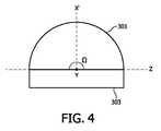
いくつかの他の実施形態では、放物曲線1は、軸xに関して、必ずしも完全に対称である必要はない。例えば、放物曲線1の上方半分103は、所望の光学的要件を満たすように、下方半分104とは異なるように設計することができる。 In some other embodiments, the parabolic curve 1 does not necessarily have to be completely symmetrical about the axis x. For example, the
よく知られているように、放物曲線は、放物線の任意のカーブ、又は放物線のようなカーブを指す。放物曲線は、1以上の円錐曲線セグメントを含む。円錐曲線セグメントは、放物線、双曲線、円、楕円などのセグメントであってよい。一実施形態では、放物曲線1は、いわゆる複合放物集光器型曲線(CPC)である。 As is well known, a parabola curve refers to any curve of a parabola, or a parabola-like curve. A parabolic curve includes one or more conic curve segments. A conic segment may be a parabola, hyperbola, circle, ellipse, or other segment. In one embodiment, parabolic curve 1 is a so-called compound parabolic concentrator curve (CPC).
図2は、本発明の一実施形態に従った、ベースカーブとしての複合放物集光器型曲線(CPC)の図を示している。 FIG. 2 shows a diagram of a compound parabolic concentrator curve (CPC) as a base curve, according to one embodiment of the present invention.
図2を参照すると、CPC2は、2つの傾いた放物線203、204を含み、2つの開口、すなわち、入口開口201及び出口開口202を有する。CPCは、その許容角度(acceptance angle)θmax、及び、その横方向焦点シフト(lateral focal shift)aにより特徴付けられる。図2に示される極座標系では、CPC2は、許容角度θmax及び横方向焦点シフトaの関数として、表すことができる。すなわち、CPC2は、Referring to FIG. 2, CPC 2 includes two

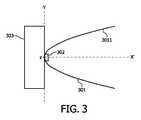
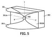
図3〜図5は、本発明の一実施形態に従った、道路照明器具用の照明装置を示しており、図3は、その照明装置の側面図、図4は、その照明装置の上面図、図5は、その照明装置の斜視図を示している。照明装置の向きは、軸x’、軸y、及び軸zにより示されている。詳細には、軸yは、照明装置内における反射鏡の反射面を形成するための放物曲線の第1の軸であり、軸x’は、出力ビーム(すわなち、照明装置により生成されるビーム)の光軸であり、軸zは、軸x’及び軸yの両方に垂直な軸である。 3 to 5 show a lighting device for a road lighting apparatus according to an embodiment of the present invention, FIG. 3 is a side view of the lighting device, and FIG. 4 is a top view of the lighting device. FIG. 5 shows a perspective view of the illumination device. The orientation of the illuminating device is indicated by the axes x ', y and z. Specifically, the axis y is the first axis of the parabola for forming the reflecting surface of the reflector in the illuminator, and the axis x ′ is the output beam (ie, generated by the illuminator). The axis z is an axis perpendicular to both the axis x ′ and the axis y.
図3〜図5を参照すると、照明装置3は、反射面3011を有する反射鏡301、及びLED光源302を備える。反射面3011は、第1の軸yの周りに所定の角度Ωだけ図1に示される放物曲線を回転することにより形成される。LED光源302は、反射面の入口に配置される。この入口は、放物曲線の入口開口に対応する。 Referring to FIGS. 3 to 5, the illumination device 3 includes a reflecting
この実施形態では、所定の角度Ωは、図4に示されるように、180°である。いくつかの他の実施形態では、所定の角度Ωは、他の値であってもよい。好ましくは、所定の角度Ωは、例えば、120°、150°など、[90°,180°]の範囲内である。 In this embodiment, the predetermined angle Ω is 180 ° as shown in FIG. In some other embodiments, the predetermined angle Ω may be other values. Preferably, the predetermined angle Ω is within a range of [90 °, 180 °], such as 120 °, 150 °, and the like.
図3又は図5に示されるように、反射面3011により、LED光源からの光は、所定の角度Ωの範囲内にある第1の軸yを含む任意の平面を指す垂直平面(vertical plane)において、同様に制御される。これは、反射面と垂直平面との交線が、同じ放物曲線であるからである。 As shown in FIG. 3 or FIG. 5, due to the
したがって、垂直平面における出力ビームの出口ビーム角(exit beam angle)は、放物曲線の最大出口角によって決まる。放物曲線の最大出口角が大きいほど、垂直平面における出口ビーム角は大きくなる。例えば、出口ビーム角は、±5°の範囲内に設定することができる。 Thus, the exit beam angle of the output beam in the vertical plane is determined by the maximum exit angle of the parabolic curve. The greater the maximum exit angle of the parabolic curve, the greater the exit beam angle in the vertical plane. For example, the exit beam angle can be set within a range of ± 5 °.
さらに、照明装置3の出力ビームは、第1の軸yと垂直な平面を指す水平平面(horizontal plane)において、ランベルト分布に従う。 Furthermore, the output beam of the illumination device 3 follows a Lambertian distribution in a horizontal plane that points to a plane perpendicular to the first axis y.
LED光源302は、1以上のLEDモジュールを含むことができる。1以上のLEDモジュールの各々は、単一チップLED又は複数チップLEDのいずれかとすることができる。一実施形態において、LED光源302は、単一のLEDモジュールにより高光束を実現するように、複数チップLEDを含むことができる。例えば、6×6mm2の効果的な発光領域を有する複数チップLEDは、30Wの電力により駆動される場合、3000Lux以上の光束をサポートすることができる。The LED
さらに図3〜図5を参照すると、照明装置3は、ヒートシンク及び電気ボックスとして機能するボックス303をさらに備える。ボックス303は、LED光源302の後方に配置される。 3 to 5, the lighting device 3 further includes a
いくつかの他の実施形態では、反射鏡301は、反射面3011に加えて、他の反射面を含むことができる。例えば、反射鏡301は、さらなる反射面3012を含むことができる。反射面3012は、2つの部分3012a、3012bを含み、その一方は、回転が開始する場所において放物曲線1と同一平面にあり、他方は、回転が終了する場所において放物曲線1と同一平面にある。さらに、LED光源302は、図5に示されるように、反射面3012の前方に配置される。 In some other embodiments, the
図6は、本発明の一実施形態に従った照明装置を取り付けるための概略図を示している。照明装置の向きは、軸x’、軸y、及び軸zにより示されるが、これらは、図3〜図5の軸と同一である。 FIG. 6 shows a schematic diagram for mounting a lighting device according to an embodiment of the present invention. The orientation of the illuminating device is indicated by axis x ', axis y and axis z, which are the same as the axes of Figs.
図6を参照すると、照明装置41は、幅Wを有する道路を照らすために、使用される。照明装置41は、道路脇の支持物体42に取り付けられる。支持物体42は、ポールであってもよいし、側壁のフェンスであってもよい。図6に示されるように、照明装置41は、照明装置41の軸zが道路の路肩と平行になる向きで、支持物体42に取り付けられる。 Referring to FIG. 6, the
好ましくは、照明装置41は、道路表面43の上方1.2m以下の高さhに取り付けられる。例えば、取付高さhは、道路表面43から1mとすることができる。 Preferably, the
さらに、照明装置41は、出力ビームの光軸x’が道路の中央に向かうように、角度γだけ傾けられる。 Further, the illuminating
そのような傾きを容易にするために、照明装置は、傾き角度γを調整可能な調整手段をさらに備えることができる。例えば、照明装置は、反射鏡及びLED光源を保持するための保持ユニットと、ベースとをさらに備えてもよく、保持ユニットが軸zの周りを回転可能なように、保持ユニットはベースに対して回転可能に接続される。 In order to facilitate such tilting, the lighting device can further include an adjusting means capable of adjusting the tilt angle γ. For example, the lighting device may further include a holding unit for holding the reflecting mirror and the LED light source, and a base, and the holding unit is relative to the base so that the holding unit can rotate about the axis z. Connected to be rotatable.
本発明の一実施形態に従うと、道路照明器具が提供される。道路照明器具は、道路に沿って取り付けられる支持物体と、照明装置の軸zが道路の路肩と平行になるように支持物体に取り付けられる照明装置とを備える。さらに、照明装置は、道路の表面から1.2m以下の高さに取り付けられる。照明装置は、照明装置の光軸x’が道路の中央に向かうように、取り付けることができる。 According to one embodiment of the present invention, a road lighting fixture is provided. The road luminaire includes a support object attached along the road and an illumination device attached to the support object so that the axis z of the illumination device is parallel to the road shoulder. Furthermore, the lighting device is mounted at a height of 1.2 m or less from the road surface. The lighting device can be mounted such that the optical axis x 'of the lighting device is directed toward the center of the road.
当業者は、本発明が上述した好適な実施形態に限定されないことを認識するであろう。そうではなく、多くの変更形態及び変形形態が、添付の特許請求の範囲内で可能である。上述した実施形態は、本発明を限定するものではなく例示するものであって、当業者は、添付の特許請求の範囲から逸脱することなく、代替的実施形態を設計することができることに留意すべきである。請求項中、括弧の間に配置されるいかなる参照符号も請求項を限定するものと解釈されてはならない。用語「備える(comprise)」は、請求項に列挙した以外の要素又はステップの存在を除外しない。ある要素に先行する用語「a」又は「an」は、このような要素の複数の存在を除外しない。第1の、第2の、及び、第3の、といった用語の使用は、順序を示すものではない。これらの用語は、名称として解釈されるべきである。明確に示されない限り、動作について特定の順序を求めることは意図しない。 Those skilled in the art will recognize that the present invention is not limited to the preferred embodiments described above. Rather, many modifications and variations are possible within the scope of the appended claims. The above-described embodiments are illustrative rather than limiting, and one skilled in the art can design alternative embodiments without departing from the scope of the appended claims. Should. In the claims, any reference signs placed between parentheses shall not be construed as limiting the claim. The term “comprise” does not exclude the presence of elements or steps other than those listed in a claim. The term “a” or “an” preceding an element does not exclude the presence of a plurality of such elements. The use of the terms first, second, and third does not indicate an order. These terms should be interpreted as names. It is not intended to require a specific order of operation unless explicitly indicated.
Claims (13)
Translated fromJapanese第1の軸の周りに所定の角度だけ放物曲線を回転することにより形成された反射面を有する反射鏡であって、前記放物曲線は、頂点において開口を有し、前記第1の軸は、前記放物曲線と同一平面にあり、前記放物曲線の対称軸と実質的に垂直であり、前記放物曲線の前記開口に、又は前記開口の外側に位置する、反射鏡と、
前記反射面の入口に配置されたLED光源であって、前記入口は、前記放物曲線の前記開口に対応する、LED光源と、
前記反射鏡及び前記LED光源を保持するための保持ユニットと、
ベースと、
を備え、
前記保持ユニットは、前記保持ユニットが第2の軸の周りを回転可能なように、前記ベースに対して回転可能に接続され、前記第2の軸は、前記照明装置により生成されるビームの光軸、及び前記第1の軸の両方に垂直である、照明装置。A lighting device for road lighting equipment,
A reflecting mirror having a reflecting surface formed by rotating a parabolic curve about a first axis by a predetermined angle, the parabolic curve having an opening at a vertex, and the first axis A reflector that is coplanar with the parabolic curve, substantially perpendicular to the axis of symmetry of the parabolic curve, and located at or outside the opening of the parabolic curve;
An LED light source disposed at an entrance of the reflective surface, the entrance corresponding to the opening of the parabolic curve; and
A holding unit for holding the reflecting mirror and the LED light source;
Base and
Equipped witha,
The holding unit is rotatably connected to the base such that the holding unit is rotatable about a second axis, the second axis being a beam of light generated by the illumination device An illumination devicethat is perpendicular to both the axis and the first axis .
放物線のセグメント;
双曲線のセグメント;
円のセグメント;及び
楕円のセグメント;
のうち少なくとも1つを含む、請求項2記載の照明装置。The one or more conic segments are
Parabolic segment;
Hyperbolic segments;
A circle segment; and an oval segment;
The lighting device according to claim 2, comprising at least one of the following.
請求項1乃至7いずれか一項記載の照明装置であって、前記照明装置は、前記照明装置の第2の軸が前記道路の路肩と平行になるように、前記支持物体に取り付けられ、前記第2の軸は、前記照明装置により生成される前記ビームの前記光軸、及び前記第1の軸の両方に垂直である、照明装置と、
を備えた、道路照明器具。A supporting object attached along the road;
The lighting device according to any one of claims 1 to7 , wherein the lighting device is attached to the supporting object so that a second axis of the lighting device is parallel to a shoulder of the road, second axis,the optical axis ofthe beam generated by the lighting device, and is perpendicular to both said first axis, an illumination device,
With road lighting equipment.
The road illuminator according to claim8 , wherein the lighting device is mounted such that the optical axis of the beam generated by the lighting device is directed toward the center of the road.
前記照明装置の第2の軸が道路の路肩と平行になるように、前記道路の脇に前記照明装置を取り付けるステップであって、前記第2の軸は、前記照明装置により生成される前記ビームの前記光軸、及び前記第1の軸の両方に垂直である、取り付けるステップ
を含む、方法。A method for attaching the lighting device according to any one of claims 1 to7 ,
As the second axis of the lighting device is parallel to the shoulder of a road, comprising the steps of attaching the lighting device on the side of the road, said second axis,said beam generated by said illumination devicethe optical axis of, and is perpendicular to both said first axis, including the step of attaching method.
をさらに含む、請求項11記載の方法。The method of claim11 , further comprising: attaching the lighting device to a height that is 1.2 m or less from the surface of the road.
をさらに含む、請求項11記載の方法。The method of claim11 , further comprising directing the optical axis of the beam generated by the illuminating device toward a center of the road.
Applications Claiming Priority (3)
| Application Number | Priority Date | Filing Date | Title |
|---|---|---|---|
| CN2011082610 | 2011-11-22 | ||
| CNPCT/CN2011/082610 | 2011-11-22 | ||
| PCT/IB2012/055823WO2013076597A1 (en) | 2011-11-22 | 2012-10-23 | A lighting device and a road lighting luminaire comprising the lighting device. |
Publications (2)
| Publication Number | Publication Date |
|---|---|
| JP2014533874A JP2014533874A (en) | 2014-12-15 |
| JP6178796B2true JP6178796B2 (en) | 2017-08-09 |
Family
ID=47557404
Family Applications (1)
| Application Number | Title | Priority Date | Filing Date |
|---|---|---|---|
| JP2014541774AExpired - Fee RelatedJP6178796B2 (en) | 2011-11-22 | 2012-10-23 | LIGHTING DEVICE AND ROAD LIGHTING EQUIPMENT HAVING THE LIGHTING DEVICE |
Country Status (7)
| Country | Link |
|---|---|
| US (1) | US9395064B2 (en) |
| EP (1) | EP2748524B1 (en) |
| JP (1) | JP6178796B2 (en) |
| BR (1) | BR112014011980A8 (en) |
| IN (1) | IN2014CN03725A (en) |
| RU (1) | RU2627728C2 (en) |
| WO (1) | WO2013076597A1 (en) |
Families Citing this family (2)
| Publication number | Priority date | Publication date | Assignee | Title |
|---|---|---|---|---|
| JP6277604B2 (en)* | 2013-05-31 | 2018-02-14 | 岩崎電気株式会社 | lighting equipment |
| CN105020636B (en)* | 2015-08-20 | 2017-09-19 | 山东交通学院 | A low-level lighting fixture for a tunnel |
Family Cites Families (19)
| Publication number | Priority date | Publication date | Assignee | Title |
|---|---|---|---|---|
| US5055984A (en)* | 1989-08-11 | 1991-10-08 | The Brinkmann Corporation | Solar rechargeable light |
| RU2076284C1 (en)* | 1993-03-01 | 1997-03-27 | Борис Николаевич Гроздов | Steel hot-water boiler "farmer" |
| JP3992160B2 (en)* | 1996-05-07 | 2007-10-17 | 東芝ライテック株式会社 | Illumination control method for horizont light |
| JP2003344958A (en)* | 2002-05-27 | 2003-12-03 | Canon Inc | Optical element and lighting device having the same |
| EP1692430A4 (en)* | 2003-12-08 | 2008-05-21 | Coleman Co | Eliptical reflector and curved lens system for a portable light |
| JP4564917B2 (en)* | 2005-12-12 | 2010-10-20 | 株式会社東亜製作所 | LED lighting |
| CN2937789Y (en) | 2006-08-09 | 2007-08-22 | 贵州首朗新能源有限公司 | Low-altitude illumination LED high-efficiency energy-saving street lamps |
| US7828461B2 (en)* | 2007-07-16 | 2010-11-09 | Lumination Llc | LED luminaire for generating substantially uniform illumination on a target plane |
| ES2376371T3 (en)* | 2007-07-25 | 2012-03-13 | Intav S.R.L. | LIGHTING DEVICE, IN PARTICULAR SUPPLEMENTARY LIGHT SIGNALING DEVICE FOR PRIORITY RESCUE AND EMERGENCY VEHICLES. |
| CN201110482Y (en)* | 2007-09-04 | 2008-09-03 | 索恩照明(天津)有限公司 | Embedded type low glare road lighting lamp |
| US7828456B2 (en)* | 2007-10-17 | 2010-11-09 | Lsi Industries, Inc. | Roadway luminaire and methods of use |
| JP5263658B2 (en) | 2007-11-30 | 2013-08-14 | 東芝ライテック株式会社 | Lighting device |
| CN101619823A (en) | 2008-07-02 | 2010-01-06 | 富士迈半导体精密工业(上海)有限公司 | LED street lamp |
| JP5407054B2 (en)* | 2008-08-01 | 2014-02-05 | 日亜化学工業株式会社 | Lighting device |
| US8622569B1 (en)* | 2009-07-17 | 2014-01-07 | Musco Corporation | Method, system and apparatus for controlling light distribution using swivel-mount led light sources |
| CN102086989A (en)* | 2009-12-07 | 2011-06-08 | 北京通力环电气股份有限公司 | Light emitting diode (LED) lamp and street lamp using same |
| JP5356273B2 (en)* | 2010-02-05 | 2013-12-04 | シャープ株式会社 | LIGHTING DEVICE AND LIGHTING DEVICE PROVIDED WITH THE LIGHTING DEVICE |
| JP5527529B2 (en)* | 2010-03-25 | 2014-06-18 | スタンレー電気株式会社 | Lighting device |
| CN102168831B (en) | 2011-03-22 | 2014-04-02 | 王剑波 | Low-position acute angle road illuminating lamp and illuminating and installation method thereof |
- 2012
- 2012-10-23JPJP2014541774Apatent/JP6178796B2/ennot_activeExpired - Fee Related
- 2012-10-23EPEP12813971.4Apatent/EP2748524B1/ennot_activeNot-in-force
- 2012-10-23ININ3725CHN2014patent/IN2014CN03725A/enunknown
- 2012-10-23USUS14/359,628patent/US9395064B2/ennot_activeExpired - Fee Related
- 2012-10-23BRBR112014011980Apatent/BR112014011980A8/ennot_activeIP Right Cessation
- 2012-10-23RURU2014125199Apatent/RU2627728C2/enactive
- 2012-10-23WOPCT/IB2012/055823patent/WO2013076597A1/enactiveApplication Filing
Also Published As
| Publication number | Publication date |
|---|---|
| RU2627728C2 (en) | 2017-08-11 |
| EP2748524B1 (en) | 2016-10-19 |
| EP2748524A1 (en) | 2014-07-02 |
| US20140313736A1 (en) | 2014-10-23 |
| WO2013076597A1 (en) | 2013-05-30 |
| BR112014011980A8 (en) | 2017-07-11 |
| US9395064B2 (en) | 2016-07-19 |
| IN2014CN03725A (en) | 2015-07-03 |
| RU2014125199A (en) | 2015-12-27 |
| BR112014011980A2 (en) | 2017-05-30 |
| JP2014533874A (en) | 2014-12-15 |
Similar Documents
| Publication | Publication Date | Title |
|---|---|---|
| JP5257609B2 (en) | Optical module and lighting fixture | |
| US8419215B2 (en) | LED lamp and street lamp using the same | |
| JP5020035B2 (en) | Lighting fixture with support | |
| CN101561087A (en) | LED flat light source structure | |
| JP6178796B2 (en) | LIGHTING DEVICE AND ROAD LIGHTING EQUIPMENT HAVING THE LIGHTING DEVICE | |
| JP6518893B2 (en) | Light distribution and dispersion control type LED lighting device | |
| US7213949B2 (en) | Four segment reflector | |
| CN202032384U (en) | Reflection-type LED cyclorama light | |
| KR101741146B1 (en) | LED lighting device | |
| JP2015506538A (en) | Spatial lighting method | |
| CN103370571A (en) | A lighting device and a luminaire comprising the lighting device | |
| JP5797241B2 (en) | Street light | |
| CN102080792B (en) | Reflection type light-emitting diode (LED) cyclorama light | |
| JP2003281910A (en) | Luminaire | |
| CN103032746B (en) | A kind of LED light source module and LED light source thereof | |
| JP2014503111A (en) | Lighting device and lighting fixture having the lighting device | |
| CN202040632U (en) | LED plane light source device | |
| CN103946628B (en) | Lighting equipment and road lighting fixtures including lighting equipment | |
| CN220792855U (en) | Anti-glare underground lamp for wide-angle light emitting | |
| JPWO2013183205A1 (en) | Lighting fixture unit | |
| KR101049834B1 (en) | LED lighting device with LED glare and LED lighting device for easy glare prevention and light distribution control | |
| KR101283361B1 (en) | LED lighting system | |
| Schmidt | 3.7 Luminaire Designs | |
| TW200540365A (en) | Lighting fixture | |
| CN106641916A (en) | Lighting fixture for sports venue |
Legal Events
| Date | Code | Title | Description |
|---|---|---|---|
| RD02 | Notification of acceptance of power of attorney | Free format text:JAPANESE INTERMEDIATE CODE: A7422 Effective date:20150612 | |
| A621 | Written request for application examination | Free format text:JAPANESE INTERMEDIATE CODE: A621 Effective date:20151020 | |
| A977 | Report on retrieval | Free format text:JAPANESE INTERMEDIATE CODE: A971007 Effective date:20160831 | |
| A131 | Notification of reasons for refusal | Free format text:JAPANESE INTERMEDIATE CODE: A131 Effective date:20160907 | |
| A711 | Notification of change in applicant | Free format text:JAPANESE INTERMEDIATE CODE: A711 Effective date:20160927 | |
| TRDD | Decision of grant or rejection written | ||
| A01 | Written decision to grant a patent or to grant a registration (utility model) | Free format text:JAPANESE INTERMEDIATE CODE: A01 Effective date:20170619 | |
| A61 | First payment of annual fees (during grant procedure) | Free format text:JAPANESE INTERMEDIATE CODE: A61 Effective date:20170714 | |
| R150 | Certificate of patent or registration of utility model | Ref document number:6178796 Country of ref document:JP Free format text:JAPANESE INTERMEDIATE CODE: R150 | |
| S531 | Written request for registration of change of domicile | Free format text:JAPANESE INTERMEDIATE CODE: R313531 | |
| S533 | Written request for registration of change of name | Free format text:JAPANESE INTERMEDIATE CODE: R313533 | |
| R350 | Written notification of registration of transfer | Free format text:JAPANESE INTERMEDIATE CODE: R350 | |
| R250 | Receipt of annual fees | Free format text:JAPANESE INTERMEDIATE CODE: R250 | |
| R250 | Receipt of annual fees | Free format text:JAPANESE INTERMEDIATE CODE: R250 | |
| R250 | Receipt of annual fees | Free format text:JAPANESE INTERMEDIATE CODE: R250 | |
| LAPS | Cancellation because of no payment of annual fees |