Movatterモバイル変換


[0]ホーム

URL:


JP6178533B1 - Indwelling needle puncture device - Google Patents

Indwelling needle puncture device
Download PDF

Info

Publication number
JP6178533B1
JP6178533B1JP2017055710AJP2017055710AJP6178533B1JP 6178533 B1JP6178533 B1JP 6178533B1JP 2017055710 AJP2017055710 AJP 2017055710AJP 2017055710 AJP2017055710 AJP 2017055710AJP 6178533 B1JP6178533 B1JP 6178533B1
Authority
JP
Japan
Prior art keywords
inner needle
needle
restriction
restricting
restricting portion
Prior art date
Legal status (The legal status is an assumption and is not a legal conclusion. Google has not performed a legal analysis and makes no representation as to the accuracy of the status listed.)
Expired - Fee Related
Application number
JP2017055710A
Other languages
Japanese (ja)
Other versions
JP2018157890A (en
Inventor
今井 孝典
孝典 今井
廣田 淳
淳 廣田
Current Assignee (The listed assignees may be inaccurate. Google has not performed a legal analysis and makes no representation or warranty as to the accuracy of the list.)
FORCE ENGINEERING CO., LTD.
Original Assignee
FORCE ENGINEERING CO., LTD.
Priority date (The priority date is an assumption and is not a legal conclusion. Google has not performed a legal analysis and makes no representation as to the accuracy of the date listed.)
Filing date
Publication date
Application filed by FORCE ENGINEERING CO., LTD.filedCriticalFORCE ENGINEERING CO., LTD.
Priority to JP2017055710ApriorityCriticalpatent/JP6178533B1/en
Application grantedgrantedCritical
Publication of JP6178533B1publicationCriticalpatent/JP6178533B1/en
Publication of JP2018157890ApublicationCriticalpatent/JP2018157890A/en
Expired - Fee Relatedlegal-statusCriticalCurrent
Anticipated expirationlegal-statusCritical

Links

Images

Landscapes

Abstract

Translated fromJapanese

【課題】留置針穿刺具において第1規制部及び第2規制部の配置の自由度を高める。【解決手段】留置針穿刺具1は、操作部13が中間部を支点13aとして揺動操作可能であり、該揺動操作に伴う一端部及び他端部の背反方向の変位を利用して第1規制部11及び第2規制部12による規制を解除することで、同方向の変位に基づいて第1規制部11及び第2規制部12による規制を解除する場合に比べ、第1規制部11と第2規制部12とを離間して配置するなど、第1規制部11及び第2規制部12の配置の自由度が高められる。【選択図】図1In an indwelling needle puncture device, the degree of freedom of arrangement of a first restricting portion and a second restricting portion is increased. In an indwelling needle puncture device, an operation portion can be swung with an intermediate portion as a fulcrum 13a. By releasing the restriction by the first restricting part 11 and the second restricting part 12, the first restricting part 11 is compared with the case of releasing the restriction by the first restricting part 11 and the second restricting part 12 based on the displacement in the same direction. The degree of freedom of arrangement of the first restricting portion 11 and the second restricting portion 12 is increased, for example, by disposing the first restricting portion 12 and the second restricting portion 12 apart from each other. [Selection] Figure 1

Description

Translated fromJapanese

本発明は、生体組織に留置針を穿刺するための留置針穿刺具に関する。  The present invention relates to an indwelling needle puncture device for piercing a living tissue with an indwelling needle.

生体組織に穿刺され、かつ生体組織に留置される外針と、外針の基部に連結される外針ハブと、外針の内部に基端側から挿通され、かつ外針の前端から突出する先端に鋭利な刃先部を有する内針と、内針の基部に連結される内針ハブと、を備える留置針穿刺具が知られている。  An outer needle that is punctured and placed in the living tissue, an outer needle hub that is connected to the base of the outer needle, and an inner needle that is inserted from the proximal end side and protrudes from the front end of the outer needle There is known an indwelling needle puncture device including an inner needle having a sharp cutting edge at a distal end and an inner needle hub connected to a base portion of the inner needle.

例えば、特許文献1に示される留置針穿刺具は、内針ハブをスライド可能に支持するケースと、内針ハブを内針がケース内に引き込まれる方向に付勢する引き込み用バネと、ケースの先端部から内針の刃先方向に突出可能に設けられる筒状の突出カバーと、突出カバーを突出方向に付勢する突出用バネと、引き込み用バネによる内針の引き込みを規制する第1規制部と、突出用バネによる突出カバーの突出を規制する第2規制部と、所定の操作に応じて、第1規制部及び第2規制部による規制を解除する操作部と、を備え、第1規制部及び第2規制部による規制の解除に応じて、内針の基端側をケース内に引き込みつつ、突出カバーを突出させて内針の先端側を覆うように構成されている。このような留置針穿刺具によれば、たとえ長い内針であっても、留置針穿刺作業後に操作部を操作するだけで、内針を突出カバー及びケースで覆い安全に廃棄することが可能になる。  For example, an indwelling needle puncture device shown inPatent Document 1 includes a case that slidably supports an inner needle hub, a retracting spring that biases the inner needle hub in a direction in which the inner needle is pulled into the case, A cylindrical projecting cover provided so as to be able to project from the distal end portion toward the cutting edge of the inner needle, a projecting spring that urges the projecting cover in the projecting direction, and a first regulating unit that regulates the retraction of the inner needle by the retracting spring. And a second restriction part for restricting the protrusion of the protrusion cover by the protrusion spring, and an operation part for releasing the restriction by the first restriction part and the second restriction part according to a predetermined operation. In response to the release of the restriction by the part and the second restricting part, the base cover side of the inner needle is pulled into the case, and the protruding cover is protruded to cover the distal end side of the inner needle. According to such an indwelling needle puncture device, even if it is a long inner needle, it is possible to cover the inner needle with the protruding cover and case and safely dispose of it only by operating the operation part after the indwelling needle puncturing operation. Become.

特開2002−126090公報JP 2002-126090 A

しかしながら、特許文献1に示される留置針穿刺具では、操作部の操作に応じて、第1規制部及び第2規制部を同方向に変位させ、該変位に基づいて第1規制部及び第2規制部による規制を解除するので、第1規制部及び第2規制部の配置の自由度が低いだけでなく、各規制部の規制解除操作ストロークや規制解除操作力を個別に設定することが困難であり、操作性に改善の余地があった。  However, in the indwelling needle puncture tool shown inPatent Document 1, the first restricting portion and the second restricting portion are displaced in the same direction according to the operation of the operation portion, and the first restricting portion and the second restricting portion are based on the displacement. Since the restriction by the restriction part is released, the degree of freedom of arrangement of the first restriction part and the second restriction part is low, and it is difficult to individually set the restriction release operation stroke and the restriction release operation force of each restriction part. There was room for improvement in operability.

本発明は、上記の如き実情に鑑みこれらの課題を解決することを目的として創作されたものであって、請求項1の発明は、生体組織に穿刺され、かつ生体組織に留置される外針と、前記外針の基部に連結される外針ハブと、前記外針の内部に基端側から挿通され、かつ前記外針の前端から突出する先端に鋭利な刃先部を有する内針と、前記内針の基部に連結される内針ハブと、前記内針ハブをスライド可能に支持するケースと、前記内針ハブを前記内針が前記ケース内に引き込まれる方向に付勢する引き込み用バネと、前記ケースの先端部から前記内針の刃先方向に突出可能に設けられる筒状の突出カバーと、前記突出カバーを突出方向に付勢する突出用バネと、前記引き込み用バネによる前記内針の引き込みを規制する第1規制部と、前記突出用バネによる前記突出カバーの突出を規制する第2規制部と、所定の操作に応じて、前記第1規制部及び前記第2規制部による規制を解除する操作部と、を備え、前記第1規制部及び前記第2規制部による規制の解除に応じて、前記内針の基端側を前記ケース内に引き込みつつ、前記突出カバーを突出させて前記内針の先端側を覆う留置針穿刺具であって、前記操作部は、中間部を支点として揺動操作可能であり、該揺動操作に伴う一端部の変位に基づいて前記第1規制部による規制を解除し、かつ、該揺動操作に伴う他端部の変位に基づいて前記第2規制部による規制を解除することを特徴とする。
請求項2の発明は、請求項1に記載の留置針穿刺具であって、前記操作部は、前記支点から前記一端部までの距離と、前記支点から前記他端部までの距離と、が相違することを特徴とする。
請求項3の発明は、請求項1又は2に記載の留置針穿刺具であって、前記第1規制部及び前記第2規制部は、前記操作部と一体に形成されていることを特徴とする。
The present invention was created with the object of solving these problems in view of the above circumstances, and the invention ofclaim 1 is an outer needle that is punctured and placed in a living tissue. An outer needle hub connected to the base of the outer needle, an inner needle having a sharp cutting edge at the tip that is inserted into the outer needle from the proximal end and protrudes from the front end of the outer needle, An inner needle hub connected to the base of the inner needle; a case for slidably supporting the inner needle hub; and a retracting spring for biasing the inner needle hub in a direction in which the inner needle is pulled into the case. A cylindrical projecting cover provided to project from the tip of the case in the direction of the cutting edge of the inner needle, a projecting spring for biasing the projecting cover in the projecting direction, and the inner needle by the retracting spring A first restricting portion for restricting the pull-in of A second restricting portion for restricting the protrusion of the protruding cover by the spring for delivery; and an operation portion for releasing the restriction by the first restricting portion and the second restricting portion according to a predetermined operation, Indwelling needle puncture covering the distal end side of the inner needle by projecting the projecting cover while pulling the proximal end side of the inner needle into the case in response to the release of the regulation by the first regulating portion and the second regulating portion The operating portion can be swung with the intermediate portion as a fulcrum, and the restriction by the first restricting portion is released based on the displacement of the one end accompanying the swinging operation, and the rocking The restriction by the second restriction part is released based on the displacement of the other end part accompanying the moving operation.
Invention ofClaim 2 is the indwelling needle puncture device ofClaim 1, Comprising: The said operation part has the distance from the said fulcrum to the said one end part, and the distance from the said fulcrum to the said other end part. It is characterized by being different.
Invention ofClaim 3 is the indwelling needle puncture device ofClaim 1 or 2, Comprising: The said 1st control part and the said 2nd control part are integrally formed with the said operation part, It is characterized by the above-mentioned. To do.

請求項1の発明によれば、操作部は、中間部を支点として揺動操作可能であり、該揺動操作に伴う一端部及び他端部の背反方向の変位を利用して第1規制部及び第2規制部による規制を解除するので、同方向の変位に基づいて第1規制部及び第2規制部による規制を解除する場合に比べ、第1規制部と第2規制部とを離間して配置するなど、第1規制部及び第2規制部の配置の自由度を高めることができる。
請求項2の発明によれば、操作部は、支点から一端部までの距離と、支点から他端部までの距離と、が相違するので、各規制部の規制解除操作ストロークや規制解除操作力を個別に設定し、操作性を向上させることができる。
請求項3の発明によれば、第1規制部及び第2規制部は、操作部と一体に形成されているので、部品点数の増加や構造の複雑化も回避できる。
According to the first aspect of the present invention, the operation portion can be swung with the intermediate portion as a fulcrum, and the first restricting portion is utilized by utilizing the displacement in the contralateral direction of the one end and the other end accompanying the swing operation. Since the restriction by the second restriction part is released, the first restriction part and the second restriction part are separated from each other as compared with the case where the restriction by the first restriction part and the second restriction part is released based on the displacement in the same direction. The degree of freedom of arrangement of the first restricting portion and the second restricting portion can be increased.
According to the invention ofclaim 2, since the distance from the fulcrum to the one end is different from the distance from the fulcrum to the other end, the operation part has a restriction release operation stroke and a restriction release operation force of each restriction part. Can be set individually to improve operability.
According to the invention ofclaim 3, since the first restricting portion and the second restricting portion are formed integrally with the operation portion, an increase in the number of parts and a complicated structure can be avoided.

本発明の実施形態に係る留置針穿刺具の断面図である。It is sectional drawing of the indwelling needle puncture device which concerns on embodiment of this invention.本発明の実施形態に係る留置針穿刺具の動作説明図であり、留置針穿刺作業前の状態(着脱カバーは取り外し状態)を示す断面図である。It is operation | movement explanatory drawing of the indwelling needle puncture device which concerns on embodiment of this invention, and is sectional drawing which shows the state before an indwelling needle puncture operation | work (detachable cover is a removal state).本発明の実施形態に係る留置針穿刺具の動作説明図であり、留置針穿刺作業後の状態を示す断面図である。It is operation | movement explanatory drawing of the indwelling needle puncture device which concerns on embodiment of this invention, and is sectional drawing which shows the state after an indwelling needle puncture operation | work.本発明の実施形態に係る留置針穿刺具の動作説明図であり、操作部を操作した後の状態を示す断面図である。It is operation | movement explanatory drawing of the indwelling needle puncture device which concerns on embodiment of this invention, and is sectional drawing which shows the state after operating an operation part.

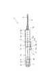
以下、本発明の実施の形態について、図面に基づいて説明する。図1に示すように、1は留置針穿刺具であって、該留置針穿刺具1は、生体組織に穿刺され、かつ生体組織に留置される外針2と、外針2の基部に連結される外針ハブ3と、外針2の内部に基端側から挿通され、かつ外針2の前端から突出する先端に鋭利な刃先部4aを有する内針4と、内針4の基部に連結される内針ハブ5と、内針ハブ5を保持する内針ハブ保持部6と、内針ハブ保持部6を介して内針ハブ5をスライド可能に支持するケース7と、内針ハブ保持部6を介して内針ハブ5を内針4がケース7内に引き込まれる方向に付勢する引き込み用バネ8と、ケース7の先端部から内針4の刃先方向に突出可能に設けられる筒状の突出カバー9と、突出カバー9を突出方向に付勢する突出用バネ10と、引き込み用バネ8による内針4の引き込みを規制する第1規制部11と、突出用バネ10による突出カバー9の突出を規制する第2規制部12と、所定の操作に応じて、第1規制部11及び第2規制部12による規制を解除する操作部13と、未使用時において外針2及び内針4を覆う着脱可能な着脱カバー14と、を備える。  Hereinafter, embodiments of the present invention will be described with reference to the drawings. As shown in FIG. 1,reference numeral 1 denotes an indwelling needle puncture device. The indwellingneedle puncture device 1 is connected to anouter needle 2 that is punctured and placed in a living tissue, and a base of theouter needle 2. Anouter needle hub 3, aninner needle 4 that is inserted into theouter needle 2 from the proximal end side and has asharp cutting edge 4 a at the distal end protruding from the front end of theouter needle 2, and a base portion of theinner needle 4. Theinner needle hub 5 to be connected, the inner needlehub holding portion 6 that holds theinner needle hub 5, the case 7 that supports theinner needle hub 5 slidably via the inner needlehub holding portion 6, and the inner needle hub A retractingspring 8 that urges theinner needle hub 5 in a direction in which theinner needle 4 is pulled into the case 7 through theholding portion 6, and a protrusion of theinner needle 4 from the distal end portion of the case 7 toward the cutting edge of theinner needle 4 are provided. Acylindrical projecting cover 9, a projectingspring 10 that biases the projectingcover 9 in the projecting direction, and aninner needle 4 by a retractingspring 8. By the first restrictingportion 11 that restricts the pull-in, the second restrictingportion 12 that restricts the protrusion of the protrudingcover 9 by the protrudingspring 10, and the first restrictingportion 11 and the second restrictingportion 12 according to a predetermined operation. Anoperation unit 13 for releasing the regulation and a detachabledetachable cover 14 that covers theouter needle 2 and theinner needle 4 when not in use are provided.

そして、留置針穿刺具1は、第1規制部11及び第2規制部12による規制の解除に応じて、内針4の基端側をケース7内に引き込みつつ、突出カバー9を突出させて内針4の先端側を覆う。これにより、たとえ長い内針4であっても、留置針穿刺作業後に操作部13を操作するだけで、内針4を突出カバー9及びケース7で覆い安全に廃棄することが可能になる。以下、本実施形態に係る留置針穿刺具1の各部について具体的に説明する。  Then, the indwellingneedle puncture device 1 causes the protrudingcover 9 to protrude while pulling the proximal end side of theinner needle 4 into the case 7 in accordance with the release of the restriction by thefirst restriction part 11 and thesecond restriction part 12. The tip side of theinner needle 4 is covered. As a result, even if theinner needle 4 is long, theinner needle 4 can be covered with the protrudingcover 9 and the case 7 and disposed of safely only by operating theoperation portion 13 after the indwelling needle puncturing operation. Hereinafter, each part of the indwellingneedle puncture device 1 according to the present embodiment will be specifically described.

ケース7は、後端部が閉じられた有底円筒形状を有し、先端部には、オスルアーを構成する中空状の外針ハブ保持部7aが突出形成されている。内針4は、硬質素材からなる中実針又は中空針であって、ケース7にスライド可能に収容される内針ハブ5から前方に延出するとともに、外針ハブ保持部7aの中空部を通ってケース7の外部に突出している。外針2は、可撓性を有する中空針であって、その内部に内針4が挿通される。外針2の基端部に連結される外針ハブ3は、メスルアーを構成し、ケース7の外針ハブ保持部7aに着脱可能に保持される。  The case 7 has a bottomed cylindrical shape whose rear end is closed, and a hollow outer needlehub holding portion 7a that constitutes a male luer protrudes from the tip. Theinner needle 4 is a solid needle or a hollow needle made of a hard material. Theinner needle 4 extends forward from theinner needle hub 5 slidably received in the case 7 and the hollow portion of the outer needlehub holding portion 7a. It passes through and protrudes outside the case 7. Theouter needle 2 is a hollow needle having flexibility, and theinner needle 4 is inserted through the inside thereof. Theouter needle hub 3 connected to the base end portion of theouter needle 2 forms a female luer and is detachably held by the outer needlehub holding portion 7a of the case 7.

ケース7の内部は、隔壁7bによって前室7cと後室7dとに分けられており、内針ハブ5及び内針ハブ保持部6は、後室7dに前後スライド可能に収容され、内針4は、隔壁7bの中央部に形成される孔7eを介して前室7c側に延出している。  The inside of the case 7 is divided into afront chamber 7c and arear chamber 7d by apartition wall 7b. Theinner needle hub 5 and the inner needlehub holding portion 6 are accommodated in therear chamber 7d so as to be slidable back and forth. Is extended to thefront chamber 7c side through ahole 7e formed in the central portion of thepartition wall 7b.

引き込み用バネ8は、引っ張りコイルスプリングであり、一端がケース7の底部に連結され、他端が内針ハブ保持部6に連結される状態で後室7dに収容されている。第1規制部11は、後室7dの前端位置で内針ハブ保持部6を係止することにより、引き込み用バネ8による内針4の引き込みを規制している。本実施形態の第1規制部11は、ケース7の外周側から、ケース7の外周部に形成される孔7fを介して、内針ハブ保持部6の外周部に形成される係合孔6aに係合する係合ピンであり、内針ハブ保持部6の係合孔6aから第1規制部11を抜くことにより、引き込み用バネ8による内針4の引き込みが許容される。  The retractingspring 8 is a tension coil spring, and is housed in therear chamber 7d with one end connected to the bottom of the case 7 and the other end connected to the inner needlehub holding part 6. Thefirst restricting portion 11 restricts the retraction of theinner needle 4 by theretraction spring 8 by locking the inner needlehub holding portion 6 at the front end position of therear chamber 7d. The first restrictingportion 11 of the present embodiment has anengagement hole 6 a formed in the outer peripheral portion of the inner needlehub holding portion 6 from the outer peripheral side of the case 7 through ahole 7 f formed in the outer peripheral portion of the case 7. By pulling out the first restrictingportion 11 from theengaging hole 6 a of the inner needlehub holding portion 6, theinner needle 4 can be retracted by the retractingspring 8.

突出カバー9は、内針4の基端側を覆う状態でケース7の前室7cに収容されるとともに、外針ハブ保持部7aの中空部を介してケース7の前端部から前方に向けて突出可能に設けられている。突出用バネ10は、圧縮コイルスプリングであり、突出カバー9の後端部に形成されるフランジ9aと隔壁7bとの間に配置されている。第2規制部12は、突出カバー9の後端部に形成されるフランジ9aを係止することにより、突出用バネ10による突出カバー9の突出を規制している。本実施形態の第2規制部12は、ケース7に対して径方向にスライド可能なプレート部材であり、フランジ9aの通過を許容するフランジ通過孔12aを備える。そして、第2規制部12は、初期状態において、フランジ通過孔12aの縁部でフランジ9aを係止することにより、突出用バネ10による突出カバー9の突出を規制する一方、押し込み操作されると、フランジ通過孔12aの縁部によるフランジ9aの係止を解除することで、突出用バネ10による突出カバー9の突出を許容する。  The protrudingcover 9 is accommodated in thefront chamber 7c of the case 7 so as to cover the proximal end side of theinner needle 4, and forwardly from the front end portion of the case 7 through the hollow portion of the outer needlehub holding portion 7a. It is provided so that it can protrude. The protrudingspring 10 is a compression coil spring, and is disposed between theflange 9a formed at the rear end portion of the protrudingcover 9 and thepartition wall 7b. The second restrictingportion 12 restricts the protrusion of theprotrusion cover 9 by theprotrusion spring 10 by locking aflange 9 a formed at the rear end portion of theprotrusion cover 9. The2nd control part 12 of this embodiment is a plate member which can be slid to radial direction with respect to case 7, and is provided with theflange passage hole 12a which accept | permits passage of theflange 9a. Then, in the initial state, the second restrictingportion 12 restricts the protrusion of theprotrusion cover 9 by theprotrusion spring 10 by locking theflange 9a at the edge of theflange passage hole 12a, while being pushed. The protrusion of theprotrusion cover 9 by theprotrusion spring 10 is allowed by releasing the locking of theflange 9a by the edge of theflange passage hole 12a.

操作部13は、中間部を支点13aとして揺動操作可能であり、該揺動操作に伴う一端部の変位に基づいて第1規制部11による規制を解除し、かつ、該揺動操作に伴う他端部の変位に基づいて第2規制部12による規制を解除するように構成されている。  Theoperation portion 13 can be swung with the intermediate portion as afulcrum 13a, and the restriction by the first restrictingportion 11 is released based on the displacement of one end accompanying the swing operation, and the swing portion is accompanied by the swing operation. Based on the displacement of the other end, the restriction by thesecond restriction part 12 is released.

具体的に説明すると、本実施形態の操作部13は、ケース7の外周面に前後方向に沿って配置されるとともに、前後方向中間部に設けられる支点13aを支点として上下揺動可能に構成されている。初期状態では、操作部13の前側がケース7の外周面から離間し、且つ操作部13の後側がケース7の外周面に近接した状態であり、操作部13の前側をケース7の外周面に近接する方向に押し込むことにより揺動操作される。操作部13の前端部13bには、第2規制部12の一端部が一体的に連結されており、操作部13の操作に伴う前端部13bの押し込み方向の変位に応じて第2規制部12による突出カバー9の突出規制が解除される。また、操作部13の後端部13cには、第1規制部11の一端部が一体的に連結されており、操作部13の操作に伴う後端部13cの引き抜き方向の変位に応じて第1規制部11による内針4の引き込み規制が解除される。  Specifically, theoperation unit 13 according to the present embodiment is arranged along the front-rear direction on the outer peripheral surface of the case 7 and is configured to be able to swing up and down with afulcrum 13a provided at the intermediate part in the front-rear direction. ing. In the initial state, the front side of theoperation unit 13 is separated from the outer peripheral surface of the case 7, and the rear side of theoperation unit 13 is close to the outer peripheral surface of the case 7. The rocking operation is performed by pushing in the approaching direction. One end portion of the second restrictingportion 12 is integrally connected to thefront end portion 13 b of theoperation portion 13, and the second restrictingportion 12 according to the displacement in the pushing direction of thefront end portion 13 b accompanying the operation of theoperation portion 13. The protrusion restriction of theprotrusion cover 9 due to is released. In addition, one end of the first restrictingportion 11 is integrally connected to therear end portion 13c of theoperation portion 13, and thefirst end portion 13c is connected to therear end portion 13c in accordance with the displacement of therear end portion 13c in accordance with the operation of theoperation portion 13. 1 Pull-in restriction of theinner needle 4 by the restrictingpart 11 is released.

操作部13は、支点13aから後端部13cまでの距離L1と、支点13aから前端部13bまでの距離L2と、が相違している。これにより、各規制部11、12の規制解除操作ストロークや規制解除操作力を個別に設定し、操作性を向上させることが可能になる。例えば、本実施形態では、引き込み用バネ8の付勢力を突出用バネ10の付勢力よりも大きくしているため、第1規制部11の規制解除操作力が第2規制部12の規制操作力よりも大きくなるが、距離L1を距離L2よりも小さくすることで、梃子の原理に基づいて第1規制部11の規制解除操作力が軽減されている。  Theoperation unit 13 is different in a distance L1 from thefulcrum 13a to therear end 13c and a distance L2 from thefulcrum 13a to thefront end 13b. As a result, it is possible to individually set the regulation release operation stroke and regulation release operation force of eachregulation unit 11 and 12 and improve operability. For example, in this embodiment, since the urging force of the retractingspring 8 is greater than the urging force of the protrudingspring 10, the restriction releasing operation force of the first restrictingportion 11 is the restricting operating force of the second restrictingportion 12. However, by making the distance L1 smaller than the distance L2, the restriction releasing operation force of the first restrictingportion 11 is reduced based on the lever principle.

つぎに、留置針穿刺具1の動作(操作手順)について、図2〜図4を参照して説明する。  Next, the operation (operation procedure) of the indwellingneedle puncture device 1 will be described with reference to FIGS.

図2に示すように、留置針穿刺具1を使用する場合は、まず、着脱カバー14を外す。これにより、外針2及び内針4を生体組織に穿刺し、外針2を生体組織に留置する留置針穿刺作業を行うことが可能になる。  As shown in FIG. 2, when using the indwellingneedle puncture device 1, first, thedetachable cover 14 is removed. This makes it possible to perform an indwelling needle puncturing operation in which theouter needle 2 and theinner needle 4 are punctured into the living tissue and theouter needle 2 is placed in the living tissue.

図3に示すように、留置針穿刺作業が終わったら、操作部13の前側を押し込み操作する。操作部13の前側を押し込み操作すると、図4に示すように、操作部13の操作に伴う前端部13bの押し込み方向の変位に応じて第2規制部12による突出カバー9の突出規制が解除されるとともに、操作部13の操作に伴う後端部13cの引き抜き方向の変位に応じて第1規制部11による内針4の引き込み規制が解除される。これにより、内針4の基端側をケース7内に引き込みつつ、突出カバー9を突出させて内針4の先端側を覆うことができ、その結果、たとえ長い内針4であっても、内針4を突出カバー9及びケース7で覆い安全に廃棄することが可能になる。  As shown in FIG. 3, when the indwelling needle puncturing operation is completed, the front side of theoperation unit 13 is pushed in. When the front side of theoperation part 13 is pushed in, as shown in FIG. 4, the protrusion restriction of theprotrusion cover 9 by thesecond restriction part 12 is released according to the displacement in the pushing direction of thefront end part 13 b accompanying the operation of theoperation part 13. At the same time, the restriction of theinner needle 4 by the first restrictingportion 11 is released according to the displacement in the pulling direction of therear end portion 13c accompanying the operation of theoperation portion 13. Thereby, while pulling the proximal end side of theinner needle 4 into the case 7, the protrudingcover 9 can be protruded to cover the distal end side of theinner needle 4. As a result, even if theinner needle 4 is long, Theinner needle 4 is covered with the protrudingcover 9 and the case 7 and can be safely discarded.

叙述の如く構成された本実施形態の留置針穿刺具1によれば、操作部13は、中間部を支点13aとして揺動操作可能であり、該揺動操作に伴う一端部及び他端部の背反方向の変位を利用して第1規制部11及び第2規制部12による規制を解除するので、同方向の変位に基づいて第1規制部11及び第2規制部12による規制を解除する場合に比べ、第1規制部11と第2規制部12とを離間して配置するなど、第1規制部11及び第2規制部12の配置の自由度を高めることができる。  According to the indwellingneedle puncture device 1 of the present embodiment configured as described above, theoperation portion 13 can be swung with the intermediate portion as afulcrum 13a, and the one end and the other end of the swivel operation are provided. Since the restriction by thefirst restriction part 11 and thesecond restriction part 12 is released using the displacement in the contralateral direction, the restriction by thefirst restriction part 11 and thesecond restriction part 12 is released based on the displacement in the same direction. Compared to the above, it is possible to increase the degree of freedom of arrangement of the first restrictingportion 11 and the second restrictingportion 12 such as arranging the first restrictingportion 11 and the second restrictingportion 12 apart from each other.

また、操作部13は、支点13aから後端部13cまでの距離L1と、支点13aから前端部13bまでの距離L2と、が相違するので、各規制部11、12の規制解除操作ストロークや規制解除操作力を個別に設定し、操作性を向上させることができる。  Moreover, since the distance L1 from thefulcrum 13a to the rear-end part 13c and the distance L2 from thefulcrum 13a to the front-end part 13b differ in theoperation part 13, the restriction release operation stroke and restriction | regulation of eachrestriction part 11 and 12 are carried out. The release operation force can be set individually to improve operability.

また、第1規制部11及び第2規制部12は、操作部13と一体に形成されているので、部品点数の増加や構造の複雑化も回避できる。  Moreover, since the1st control part 11 and the2nd control part 12 are integrally formed with theoperation part 13, the increase in a number of parts and complication of a structure can also be avoided.

また、本実施形態の留置針穿刺具1によれば、使用時には、外針2及び内針4が露出する長尺状態で良好に留置針穿刺作業を行うことができるだけでなく、使用後においては、内針4の基端側をケース7内に引き込みつつ、突出カバー9を突出させて内針4の先端側を覆うことにより、使用時よりも短尺な状態で安全に廃棄することができる。  Moreover, according to the indwellingneedle puncture device 1 of the present embodiment, in use, not only can the indwelling needle puncture work be performed satisfactorily in a long state where theouter needle 2 and theinner needle 4 are exposed, but also after use. By retracting the protrudingcover 9 and covering the distal end side of theinner needle 4 while pulling the proximal end side of theinner needle 4 into the case 7, it can be safely discarded in a shorter state than in use.

1 留置針穿刺具
2 外針
3 外針ハブ
4 内針
4a 刃先部
5 内針ハブ
6 内針ハブ保持部
6a 係合孔
7 ケース
7a 外針ハブ保持部
7b 隔壁
7c 前室
7d 後室
7e 孔
7f 孔
8 引き込み用バネ
9 突出カバー
9a フランジ
10 突出用バネ
11 第1規制部
12 第2規制部
12a フランジ通過孔
13 操作部
13a 支点
13b 前端部
13c 後端部
14 着脱カバー
L1、L2 距離
DESCRIPTION OFSYMBOLS 1 Indwellingneedle puncture tool 2Outer needle 3Outer needle hub 4Inner needle 4aCutting edge part 5Inner needle hub 6 Inner needlehub holding part 6a Engagement hole 7Case 7a Outer needlehub holding part7b Partition wall7c Front chamber7d Rear chamber 7eHole 7f Hole 8 Pull-inspring 9Protrudingcover 9a Flange 10Protruding spring 11First restricting portion 12Second restricting portion 12aFlange passage hole 13Operating portion13a Support point 13bFront end portion 13cRear end portion 14 Detachable covers L1, L2 Distance

Claims (3)

Translated fromJapanese
生体組織に穿刺され、かつ生体組織に留置される外針と、
前記外針の基部に連結される外針ハブと、
前記外針の内部に基端側から挿通され、かつ前記外針の前端から突出する先端に鋭利な刃先部を有する内針と、
前記内針の基部に連結される内針ハブと、
前記内針ハブをスライド可能に支持するケースと、
前記内針ハブを前記内針が前記ケース内に引き込まれる方向に付勢する引き込み用バネと、
前記ケースの先端部から前記内針の刃先方向に突出可能に設けられる筒状の突出カバーと、
前記突出カバーを突出方向に付勢する突出用バネと、
前記引き込み用バネによる前記内針の引き込みを規制する第1規制部と、
前記突出用バネによる前記突出カバーの突出を規制する第2規制部と、
所定の操作に応じて、前記第1規制部及び前記第2規制部による規制を解除する操作部と、を備え、前記第1規制部及び前記第2規制部による規制の解除に応じて、前記内針の基端側を前記ケース内に引き込みつつ、前記突出カバーを突出させて前記内針の先端側を覆う留置針穿刺具であって、
前記操作部は、中間部を支点として揺動操作可能であり、該揺動操作に伴う一端部の変位に基づいて前記第1規制部による規制を解除し、かつ、該揺動操作に伴う他端部の変位に基づいて前記第2規制部による規制を解除することを特徴とする留置針穿刺具。
An outer needle that is punctured and placed in the living tissue;
An outer needle hub coupled to the base of the outer needle;
An inner needle inserted into the outer needle from the proximal end side and having a sharp cutting edge at the distal end protruding from the front end of the outer needle;
An inner needle hub connected to the base of the inner needle;
A case for slidably supporting the inner needle hub;
A retracting spring that biases the inner needle hub in a direction in which the inner needle is retracted into the case;
A cylindrical projecting cover provided so as to project from the tip of the case in the direction of the cutting edge of the inner needle;
A protruding spring for urging the protruding cover in the protruding direction;
A first restricting portion for restricting retraction of the inner needle by the retraction spring;
A second restricting portion for restricting the protrusion of the protrusion cover by the protrusion spring;
An operation unit that releases the restriction by the first restriction unit and the second restriction unit according to a predetermined operation, and according to the release of the restriction by the first restriction unit and the second restriction unit, An indwelling needle puncture device that covers the distal end side of the inner needle by protruding the protruding cover while pulling the proximal end side of the inner needle into the case,
The operation portion can be swung with an intermediate portion as a fulcrum, and the restriction by the first restricting portion is released based on the displacement of one end portion accompanying the swing operation, An indwelling needle puncture device, wherein the restriction by the second restriction part is released based on the displacement of the end part.
前記操作部は、前記支点から前記一端部までの距離と、前記支点から前記他端部までの距離と、が相違することを特徴とする請求項1に記載の留置針穿刺具。  The indwelling needle puncture device according to claim 1, wherein a distance from the fulcrum to the one end is different from a distance from the fulcrum to the other end. 前記第1規制部及び前記第2規制部は、前記操作部と一体に形成されていることを特徴とする請求項1又は2に記載の留置針穿刺具。  The indwelling needle puncture device according to claim 1 or 2, wherein the first restricting portion and the second restricting portion are formed integrally with the operation portion.
JP2017055710A2017-03-222017-03-22 Indwelling needle puncture deviceExpired - Fee RelatedJP6178533B1 (en)

Priority Applications (1)

Application NumberPriority DateFiling DateTitle
JP2017055710AJP6178533B1 (en)2017-03-222017-03-22 Indwelling needle puncture device

Applications Claiming Priority (1)

Application NumberPriority DateFiling DateTitle
JP2017055710AJP6178533B1 (en)2017-03-222017-03-22 Indwelling needle puncture device

Publications (2)

Publication NumberPublication Date
JP6178533B1true JP6178533B1 (en)2017-08-09
JP2018157890A JP2018157890A (en)2018-10-11

Family

ID=59559225

Family Applications (1)

Application NumberTitlePriority DateFiling Date
JP2017055710AExpired - Fee RelatedJP6178533B1 (en)2017-03-222017-03-22 Indwelling needle puncture device

Country Status (1)

CountryLink
JP (1)JP6178533B1 (en)

Families Citing this family (1)

* Cited by examiner, † Cited by third party
Publication numberPriority datePublication dateAssigneeTitle
JP7549188B2 (en)2019-07-052024-09-11株式会社トップ Indwelling needle assembly

Citations (3)

* Cited by examiner, † Cited by third party
Publication numberPriority datePublication dateAssigneeTitle
JP2002126090A (en)*2000-10-232002-05-08Nipro CorpIndwelling needle assembler
US6626868B1 (en)*1998-10-062003-09-30Dean B. PrestidgeNeedle apparatus
US20040122373A1 (en)*1997-11-122004-06-24Botich Michael J.Catheter insertion device with retractable needle

Patent Citations (3)

* Cited by examiner, † Cited by third party
Publication numberPriority datePublication dateAssigneeTitle
US20040122373A1 (en)*1997-11-122004-06-24Botich Michael J.Catheter insertion device with retractable needle
US6626868B1 (en)*1998-10-062003-09-30Dean B. PrestidgeNeedle apparatus
JP2002126090A (en)*2000-10-232002-05-08Nipro CorpIndwelling needle assembler

Also Published As

Publication numberPublication date
JP2018157890A (en)2018-10-11

Similar Documents

PublicationPublication DateTitle
JP5007793B2 (en) Indwelling needle
US7905898B2 (en)Adjustable lancet device and method
CN106859669B (en)Disposable safety blood taking needle, assembling method and using method
JP2009160151A (en) Intraocular lens insertion device
JP2005137888A (en)Intravenous catheter introducing device
JP2013179951A (en)Hair transplantation needle member
JP2013517056A (en) Puncture device with improved guidance mechanism
JP6178533B1 (en) Indwelling needle puncture device
JP5601741B1 (en) Feathered needle
JP2011182986A (en)Insertion assist tool for organ fixation device
JP2017080316A5 (en)
JP2010246945A (en) Puncture device
JP2001078991A (en)Puncture instrument
JP2017080316A (en)Medical dilation instrument
US10905360B2 (en)Push-to-charge lancing device
JP2005342325A (en) Puncture needle cartridge
JP2009261316A (en)Fishing hook remover
JP6263056B2 (en) Puncture device
JP4736042B2 (en) Indwelling needle
JP2014226157A (en)Guide device
JP4736041B2 (en) Indwelling needle
US9226700B2 (en)Detection element for determining the position of a lancet element in a lancing device
WO2016072034A1 (en)Structure for preventing buckling of piercing needle, and piercing implement provided therewith
JP5859612B2 (en) Insertion aid for organ fixation
JP4500109B2 (en) Puncture tool

Legal Events

DateCodeTitleDescription
A621Written request for application examination

Free format text:JAPANESE INTERMEDIATE CODE: A621

Effective date:20170509

A871Explanation of circumstances concerning accelerated examination

Free format text:JAPANESE INTERMEDIATE CODE: A871

Effective date:20170509

A975Report on accelerated examination

Free format text:JAPANESE INTERMEDIATE CODE: A971005

Effective date:20170627

TRDDDecision of grant or rejection written
A01Written decision to grant a patent or to grant a registration (utility model)

Free format text:JAPANESE INTERMEDIATE CODE: A01

Effective date:20170706

A61First payment of annual fees (during grant procedure)

Free format text:JAPANESE INTERMEDIATE CODE: A61

Effective date:20170713

R150Certificate of patent or registration of utility model

Ref document number:6178533

Country of ref document:JP

Free format text:JAPANESE INTERMEDIATE CODE: R150

R250Receipt of annual fees

Free format text:JAPANESE INTERMEDIATE CODE: R250

R250Receipt of annual fees

Free format text:JAPANESE INTERMEDIATE CODE: R250

LAPSCancellation because of no payment of annual fees

[8]ページ先頭

©2009-2025 Movatter.jp