JP6174017B2 - In vivo vascular seal end effector and in vivo robotic device - Google Patents
In vivo vascular seal end effector and in vivo robotic deviceDownload PDFInfo
- Publication number
- JP6174017B2 JP6174017B2JP2014514927AJP2014514927AJP6174017B2JP 6174017 B2JP6174017 B2JP 6174017B2JP 2014514927 AJP2014514927 AJP 2014514927AJP 2014514927 AJP2014514927 AJP 2014514927AJP 6174017 B2JP6174017 B2JP 6174017B2
- Authority
- JP
- Japan
- Prior art keywords
- end effector
- ablation
- shaft
- motor
- cautery
- Prior art date
- Legal status (The legal status is an assumption and is not a legal conclusion. Google has not performed a legal analysis and makes no representation as to the accuracy of the status listed.)
- Active
Links
Images


Classifications
- A—HUMAN NECESSITIES
- A61—MEDICAL OR VETERINARY SCIENCE; HYGIENE
- A61B—DIAGNOSIS; SURGERY; IDENTIFICATION
- A61B18/00—Surgical instruments, devices or methods for transferring non-mechanical forms of energy to or from the body
- A61B18/04—Surgical instruments, devices or methods for transferring non-mechanical forms of energy to or from the body by heating
- A61B18/12—Surgical instruments, devices or methods for transferring non-mechanical forms of energy to or from the body by heating by passing a current through the tissue to be heated, e.g. high-frequency current
- A61B18/14—Probes or electrodes therefor
- A61B18/1442—Probes having pivoting end effectors, e.g. forceps
- A61B18/1445—Probes having pivoting end effectors, e.g. forceps at the distal end of a shaft, e.g. forceps or scissors at the end of a rigid rod
- A—HUMAN NECESSITIES
- A61—MEDICAL OR VETERINARY SCIENCE; HYGIENE
- A61B—DIAGNOSIS; SURGERY; IDENTIFICATION
- A61B17/00—Surgical instruments, devices or methods
- A61B17/28—Surgical forceps
- A61B17/29—Forceps for use in minimally invasive surgery
- A61B2017/2901—Details of shaft
- A61B2017/2906—Multiple forceps
- A—HUMAN NECESSITIES
- A61—MEDICAL OR VETERINARY SCIENCE; HYGIENE
- A61B—DIAGNOSIS; SURGERY; IDENTIFICATION
- A61B18/00—Surgical instruments, devices or methods for transferring non-mechanical forms of energy to or from the body
- A61B2018/00315—Surgical instruments, devices or methods for transferring non-mechanical forms of energy to or from the body for treatment of particular body parts
- A61B2018/00345—Vascular system
- A—HUMAN NECESSITIES
- A61—MEDICAL OR VETERINARY SCIENCE; HYGIENE
- A61B—DIAGNOSIS; SURGERY; IDENTIFICATION
- A61B18/00—Surgical instruments, devices or methods for transferring non-mechanical forms of energy to or from the body
- A61B2018/00571—Surgical instruments, devices or methods for transferring non-mechanical forms of energy to or from the body for achieving a particular surgical effect
- A61B2018/00595—Cauterization
- A—HUMAN NECESSITIES
- A61—MEDICAL OR VETERINARY SCIENCE; HYGIENE
- A61B—DIAGNOSIS; SURGERY; IDENTIFICATION
- A61B18/00—Surgical instruments, devices or methods for transferring non-mechanical forms of energy to or from the body
- A61B2018/00571—Surgical instruments, devices or methods for transferring non-mechanical forms of energy to or from the body for achieving a particular surgical effect
- A61B2018/0063—Sealing
- A—HUMAN NECESSITIES
- A61—MEDICAL OR VETERINARY SCIENCE; HYGIENE
- A61B—DIAGNOSIS; SURGERY; IDENTIFICATION
- A61B18/00—Surgical instruments, devices or methods for transferring non-mechanical forms of energy to or from the body
- A61B18/04—Surgical instruments, devices or methods for transferring non-mechanical forms of energy to or from the body by heating
- A61B18/12—Surgical instruments, devices or methods for transferring non-mechanical forms of energy to or from the body by heating by passing a current through the tissue to be heated, e.g. high-frequency current
- A61B18/14—Probes or electrodes therefor
- A61B18/1442—Probes having pivoting end effectors, e.g. forceps
- A61B2018/1452—Probes having pivoting end effectors, e.g. forceps including means for cutting
- A61B2018/1455—Probes having pivoting end effectors, e.g. forceps including means for cutting having a moving blade for cutting tissue grasped by the jaws
- A—HUMAN NECESSITIES
- A61—MEDICAL OR VETERINARY SCIENCE; HYGIENE
- A61B—DIAGNOSIS; SURGERY; IDENTIFICATION
- A61B34/00—Computer-aided surgery; Manipulators or robots specially adapted for use in surgery
- A61B34/30—Surgical robots
- A61B2034/301—Surgical robots for introducing or steering flexible instruments inserted into the body, e.g. catheters or endoscopes
- A—HUMAN NECESSITIES
- A61—MEDICAL OR VETERINARY SCIENCE; HYGIENE
- A61B—DIAGNOSIS; SURGERY; IDENTIFICATION
- A61B34/00—Computer-aided surgery; Manipulators or robots specially adapted for use in surgery
- A61B34/30—Surgical robots
Landscapes
- Health & Medical Sciences (AREA)
- Surgery (AREA)
- Engineering & Computer Science (AREA)
- Life Sciences & Earth Sciences (AREA)
- Biomedical Technology (AREA)
- Molecular Biology (AREA)
- Nuclear Medicine, Radiotherapy & Molecular Imaging (AREA)
- Plasma & Fusion (AREA)
- Physics & Mathematics (AREA)
- Heart & Thoracic Surgery (AREA)
- Medical Informatics (AREA)
- Otolaryngology (AREA)
- Animal Behavior & Ethology (AREA)
- General Health & Medical Sciences (AREA)
- Public Health (AREA)
- Veterinary Medicine (AREA)
- Surgical Instruments (AREA)
- Manipulator (AREA)
Description
Translated fromJapanese(政府支援)
本発明は、国防総省内の遠隔医療応用研究センタ(Telemedicine and Advanced Technology Research Center)によって認められた認可番号第26−1112−0123−002号、および米航空宇宙局の競争的研究触発実験的プログラム(Experimental Program to Stimulate Competitive Research)によって認められた認可番号第26−1112−0118−001号の下で、政府支援によってなされた。したがって、米国政府は本発明において一定の権利を有するものとする。
(技術分野)
本明細書に開示する実施形態は、ロボット医療装置および/または生体内(in vivo)医療装置ならびに関連するコンポーネントを含む、さまざまな医療装置コンポーネントおよび関連するコンポーネントに関する。より詳細には、いくつかの実施形態は、「エンドエフェクタ」または「操作コンポーネント」と呼ばれることが多い、さまざまな医療装置付属部品および制御コンポーネントを含む。本明細書に開示するいくつかのエンドエフェクタ実施形態は、血管シール装置および切断装置、特に切断コンポーネントが組み込まれている双極性焼灼装置を含む。本明細書に開示する他のエンドエフェクタ実施形態は、さまざまなデュアルエンドエフェクタコンポーネントを含み、こうしたコンポーネントは2つ以上のエンドエフェクタを有している。さらなる実施形態は、上記コンポーネントを操作するシステムおよび方法に関する。(Government support)
The present invention relates to grant number 26-1112-0123-002 approved by the Telemedicine and Advanced Technology Research Center within the Department of Defense, and a competitive research-inspired experimental program of the United States Aeronautics and Space Administration. It was made with government support under grant number 26-1112-0118-001 approved by (Experimental Program to Stimulative Competitive Research). Accordingly, the US government has certain rights in this invention.
(Technical field)
Embodiments disclosed herein relate to various medical device components and related components, including robotic medical devices and / or in vivo medical devices and related components. More particularly, some embodiments include various medical device accessories and control components, often referred to as “end effectors” or “operational components”. Some end effector embodiments disclosed herein include vascular seal devices and cutting devices, particularly bipolar cautery devices that incorporate cutting components. Other end effector embodiments disclosed herein include various dual end effector components, such components having more than one end effector. Further embodiments relate to systems and methods for operating the above components.
侵襲性外科手術処置は、さまざまな病状に対処するのに必須である。可能な場合、腹腔鏡検査等の低侵襲性処置が好ましい。
しかしながら、腹腔鏡検査等の既知の低侵襲性技術は、一部には、アクセスポートのサイズのために、外科手術器具を交換する時に外科手術ツールを取り除いて新たな外科手術ツールを体腔内に挿入する必要があるため、範囲および複雑性の点で限られている。ダ・ヴィンチ(登録商標)サージカルシステム(da Vinci Surgical System)(カリフォルニア州サニーベールに所在するインテュイティブ・サージカル社(Intuitive Surgical,Inc.)から入手可能)等の既知のロボットシステムもまた、医療専門家が外科手術用ツールを取り除き新たな外科手術用ツールを腹腔内に挿入する必要があるアクセスポートにより制限され、また非常に大型かつ非常に高価であり、大部分の病院では利用することができず、知覚能力および移動能力が限られているというさらなる不都合を有する。Invasive surgical procedures are essential to address a variety of medical conditions. Where possible, minimally invasive procedures such as laparoscopy are preferred.
However, known minimally invasive techniques such as laparoscopy, in part due to the size of the access port, remove the surgical tool when replacing the surgical instrument and place a new surgical tool in the body cavity. Limited in scope and complexity because of the need to insert. Known robotic systems such as the Da Vinci® Surgical System (available from Intuitive Surgical, Inc., Sunnyvale, Calif.) Are also known to medical professionals. Limited by access ports that require surgical tools to be removed and new surgical tools inserted into the abdominal cavity, and are very large and very expensive and are not available in most hospitals , With the additional disadvantage of limited perception and mobility.
本技術分野において、改善された外科手術方法、システムおよび装置が必要とされている。 There is a need in the art for improved surgical methods, systems and devices.
本明細書では、ロボット生体内装置を含む外科手術用装置で使用されるさまざまな外科手術用エンドエフェクタ(いくつかの焼灼エンドエフェクタおよびいくつかのデュアルエンドエフェクタを含む)について考察する。 This specification discusses various surgical end effectors (including several ablation end effectors and several dual end effectors) used in surgical devices including robotic in-vivo devices.
例1では、生体内血管シール装置は、装置本体と、装置本体に動作可能に結合された双極性血管焼灼部とを備えている。装置本体は、焼灼部作動モータ、切断部作動モータ、顎作動モータ、および本体内に配置されかつ顎作動モータに動作可能に結合された焼灼部シャフトを有している。焼灼部は、焼灼部シャフトの遠位端に結合された固定顎、焼灼部シャフトの遠位端に枢動可能に連結された可動顎、および切断部作動モータに動作可能に結合された切断部を有している。さらに、焼灼部は、焼灼部作動モータに動作可能に結合されている。 In Example 1, the in-vivo blood vessel sealing device includes a device main body and a bipolar blood vessel cauterization unit operably coupled to the device main body. The apparatus body has a cautery section actuation motor, a cutting section actuation motor, a jaw actuation motor, and a cautery section shaft disposed within the body and operably coupled to the jaw actuation motor. The cautery section includes a fixed jaw coupled to the distal end of the cautery shaft, a movable jaw pivotally coupled to the distal end of the cautery shaft, and a cutting section operably coupled to the cutting section actuation motor. have. Further, the cautery section is operably coupled to the cautery section actuation motor.
例2は、焼灼部が、シャフトに対して平行な軸を中心に回転可能である、例1によるシール装置に関する。
例3は、装置本体の全長が約7.6cm(約3インチ)未満である、例1によるシール装置に関する。Example 2 relates to a sealing device according to example 1 in which the cautery part is rotatable about an axis parallel to the shaft.
Example 3 relates to a sealing device according to Example 1 wherein the overall length of the device body is less than about 7.6 cm (about 3 inches).
例4は、焼灼部の全長が約3.8cm(約1.5インチ)未満である、例1によるシール装置に関する。
例5は、生体内ロボット装置のアームに結合されたエンドエフェクタである、例1によるシール装置に関する。Example 4 relates to a sealing device according to Example 1 in which the total length of the cautery is less than about 3.8 cm (about 1.5 inches).
Example 5 relates to a sealing device according to Example 1, which is an end effector coupled to an arm of an in-vivo robotic device.
例6は、少なくとも1つのアームに動作可能に結合された装置本体を備える生体内ロボット装置であって、例1のシール装置が少なくとも1つのアームに動作可能に結合されている、生体内ロボット装置に関する。 Example 6 is an in-vivo robot apparatus comprising a device body operably coupled to at least one arm, wherein the seal apparatus of Example 1 is operably coupled to at least one arm. About.
例7では、生体内焼灼装置によって患者の組織を焼灼する方法は、生体内焼灼装置を組織の近くに配置するステップと、焼灼部を、焼灼部作動モータによって組織に対して回転可能に配置するステップと、顎作動モータによって可動顎を開放し、組織が可動顎と固定顎との間に配置されるように焼灼部を配置するステップとを含む。本方法は、顎作動モータによって可動顎を閉鎖するステップと、可動顎および固定顎を介して組織に電流を印加し、それにより組織を焼灼するステップと、切断部作動モータによって切断部を遠位方向に付勢し、それにより可動顎と固定顎との間に配置された焼灼された組織を切断するステップとをさらに含む。 In Example 7, a method of cauterizing a patient's tissue with an in-vivo ablation device includes disposing the in-vivo ablation device near the tissue, and disposing the ablation unit so as to be rotatable with respect to the tissue by an ablation unit operation motor. And opening the movable jaw with a jaw actuating motor and positioning the ablation so that the tissue is positioned between the movable jaw and the fixed jaw. The method includes the steps of closing a movable jaw with a jaw actuation motor, applying an electrical current to the tissue through the movable and fixed jaws, thereby cauterizing the tissue, and distally cutting the cut with a cutting actuator actuation motor. Biasing in a direction, thereby cutting the cauterized tissue disposed between the movable jaw and the fixed jaw.
例8では、生体内外科手術装置用の操作コンポーネントは、少なくとも1つのアクチュエータを備えたアクチュエータハウジングと、アクチュエータハウジングに動作可能に結合されたエンドエフェクタハウジングとを備えている。エンドエフェクタハウジングは、エンドエフェクタハウジングに回転可能に連結された第1エンドエフェクタ、およびエンドエフェクタハウジングに回転可能に連結された第2エンドエフェクタを備えている。 In Example 8, an operating component for an in-vivo surgical device includes an actuator housing with at least one actuator and an end effector housing operably coupled to the actuator housing. The end effector housing includes a first end effector that is rotatably connected to the end effector housing, and a second end effector that is rotatably connected to the end effector housing.
複数の実施形態が開示されているが、本発明のさらに他の実施形態が、本発明の例示的な実施形態を図示し記載する以下の詳細な説明から、当業者には明らかとなろう。理解されるように、本発明は、すべて本発明の趣旨および範囲から逸脱しないさまざまな明らかな態様での変更が可能である。したがって、図面および詳細な説明は、限定するものではなく本質的に例示するものとしてみなされるべきである。 While multiple embodiments are disclosed, still other embodiments of the present invention will become apparent to those skilled in the art from the following detailed description, which illustrates and describes exemplary embodiments of the invention. As will be realized, the invention is capable of modifications in various obvious aspects, all without departing from the spirit and scope of the present invention. Accordingly, the drawings and detailed description are to be regarded as illustrative in nature and not as restrictive.
本明細書に開示するさまざまなシステムおよび装置は、医療処置および医療システムで使用される装置に関する。より詳細には、さまざまな実施形態は、さまざまな処置装置および処置システムで使用することができるエンドエフェクタ装置に関する。たとえば、いくつかの実施形態は、血管シールエンドエフェクタ装置に関し、他の実施形態は、ロボット医療装置および/または生体内医療装置に組み込まれるかまたはそれとともに使用されるデュアルエンドエフェクタコンポーネントに関する。本明細書で用いる「デュアルエンドエフェクタ」という用語は、2つ以上の交換可能なエンドエフェクタを有する操作コンポーネントを意味するものとする。 The various systems and devices disclosed herein relate to devices used in medical procedures and systems. More particularly, the various embodiments relate to end effector devices that can be used in various treatment devices and treatment systems. For example, some embodiments relate to vascular seal end effector devices, and other embodiments relate to dual end effector components that are incorporated into or used with robotic medical devices and / or in vivo medical devices. As used herein, the term “dual end effector” shall mean an operating component having two or more interchangeable end effectors.
本明細書に開示するエンドエフェクタ装置またはコンポーネントのさまざまな実施形態を、本明細書で定義するようなロボット装置または生体内装置を含むがそれらに限定されない他のあらゆる既知の医療装置、システムおよび方法に組み込むかまたはそれらとともに使用することができることが理解される。 Various embodiments of the end effector devices or components disclosed herein may be any other known medical devices, systems, and methods, including but not limited to robotic devices or in-vivo devices as defined herein. It is understood that can be incorporated into or used with them.
たとえば、本明細書に開示するさまざまな実施形態を、同時係属米国特許出願第11/932,441号明細書(2007年10月31日に出願され「外科手術用途のロボット(Robot for Surgical Applications)」と題する)、同第11/695,944号明細書(2007年4月3日に出願され「外科手術用途のロボット(Robot for Surgical Applications)」と題する)、同第11/947,097号明細書(2007年11月27日に出願され「薬剤送達コンポーネントを備えたロボット装置および関連方法(Robotic Devices with Agent Delivery Components and Related Methods)」と題する)、同第11/932,516号明細書(2007年10月31日に出願され「外科手術用途のロボット(Robot for Surgical Applications)」と題する)、同第11/766,683号明細書(2007年6月21日に出願され「磁気結合型ロボット装置および関連方法(Magnetically Coupleable Robotic Devices and Related Methods)」と題する)、同第11/766,720号明細書(2007年6月21日に出願され「磁気結合型外科手術用ロボット装置および関連方法(Magnetically Coupleable Surgical Robotic Devices and Related Methods)」と題する)、同第11/966,741号明細書(2007年12月28日に出願され「外科手術用視覚化および装置操作方法、システムおよび装置(Methods,Systems,and Devices for Surgical Visualization and Device Manipulation)」と題する)、同第12/171,413号明細書(2008年7月11日に出願され「ロボット装置における作動の方法およびシステム(Methods and Systems of Actuation in Robotic Devices)」と題する)、同第12/192,663号明細書(2008年8月15日に出願され「医療用膨張、取付および送達装置ならびに関連方法(Medical Inflation,Attachment,and Delivery Devices and Related Methods)」と題する)、同第12/192,779号明細書(2008年8月15日に出願され「モジュール式および協働型医療装置および関連システム(Modular and Cooperative Medical Devices and Related Systems)」と題する)、同第12/324,364号明細書(2008年11月26日出願され「ロボット装置用の多機能操作コンポーネント(Multifunctional Operational Component for Robotic Devices)」と題する)、同第61/030,588号明細書(2008年2月22日に出願され位置決め可能なカメラを有する医療装置(Medical Devices having a Psitionable Camera)と題する)、同第12/971,917号明細書(2010年12月17日に出願され「モジュール式および協働型医療装置ならびに関連システムおよび方法(Modular and Cooperative Medical Devices and Related Systems and Methods)」と題する)、同第61/506,384号明細書(2011年7月11日に出願され「ロボット外科手術装置、システムおよび関連方法(Robotic Surgical Devices,Systems,and Related Methods)」と題する)、同第61/542,543号明細書(2011年10月3日に出願され「ロボット外科手術装置、システムおよび関連方法(Robotic Surgical Devices,Systems,and Related Methods)」と題する)、同第61/584,947号明細書(2012年1月10日に出願され「外科手術アクセスおよび挿入方法、システムおよび装置(Methods,Systems,and Devices,for Surgical Access and Insertion)と題する)および同第61/640,879号明細書(2012年5月1日に出願され「単孔式ロボット装置ならびに関連システムおよび方法(Single Site Robotic Device and Related Systems and Methods)」と題する)に開示されている医療装置のいずれかに組み込むかまたはそれとともに使用することができ、これら出願はすべて、全体として参照により本明細書に組み込まれる。 For example, the various embodiments disclosed herein can be found in co-pending US patent application Ser. No. 11 / 932,441 (filed Oct. 31, 2007, “Robot for Surgical Applications”). No. 11 / 695,944 (filed Apr. 3, 2007 and entitled “Robot for Surgical Applications”), No. 11 / 947,097. Description (Robotic Devices with Agent Delivery Components and Related Methods, filed Nov. 27, 2007) No. 11 / 932,516 (filed Oct. 31, 2007 entitled “Robot for Surgical Applications”), No. 11 / 766,683 (2007). No. 11 / 766,720 (filed Jun. 21, 2007), filed on Jun. 21, 2007, entitled “Magnetically Coupleable Robotics and Related Methods”. Entitled "Magnetically Coupleable Surgical Robotic Devices and Related Methods"), No. 11 / 966,741 (filed Dec. 28, 2007 and entitled “Surgical Visualization and Device Operation Methods, Systems and Devices”). No. 12 / 171,413 (titled “Methods and Systems of Actuation in Robotic Devices” filed July 11, 2008), 12 / 171,413. No. 192,663 (filed on Aug. 15, 2008, “Medical Inflation, Attachment and Delivery Device and Related Methods (Medical Inflation, A (tachment, and Delivery Devices and Related Methods), 12 / 192,779 (filed Aug. 15, 2008, “Modular and Cooperative Medical Devices and Related Systems”). No. 12 / 324,364 (filed Nov. 26, 2008 and entitled “Multifunctional Operational Components for Robotic Devices”). No. 61 / 030,588 (filed on February 22, 2008 for positioning) Medical device having a camera (Medical Devices having a Positionable Camera), No. 12 / 971,917 (filed on Dec. 17, 2010, “Modular and collaborative medical devices and related systems” And the method (Modular and Cooperative Medical Devices and Related Systems and Methods), 61 / 506,384 (filed Jul. 11, 2011, "Robot Surgical Apparatus, System and Related Methods ( Robotic Surgical Devices, Systems, and Related Methods), 61 / 542,543. No. 61 / 584,947 (2012, filed Oct. 3, 2011, entitled “Robotic Surgical Devices, Systems, and Related Methods)”. Filed Jan. 10, entitled “Surgical Access and Insertion Methods, Systems and Devices (Methods, Systems, and Devices, for Surgical Access and Insertion)” and 61 / 640,879 (May 2012). "Single-hole robotic device and related system and method" (Single Site Robotic Device and Related Systems and Can be incorporated into or used in conjunction with any of the medical devices disclosed under "Methods"), all of which are incorporated herein by reference in their entirety.
いくつかの例示的な実施形態によれば、本明細書に開示するさまざまな実施形態のいずれも、NOTES装置等の、経管腔的内視鏡手術(natural orifice translumenal endoscopic surgical)装置に組み込むかまたはそれとともに使用することができる。当業者は、本技術分野において既知である特徴とともに本明細書に開示する特徴を含む特徴のさまざまな組合せが利用可能であることを、認識し理解するであろう。 In accordance with some exemplary embodiments, any of the various embodiments disclosed herein may be incorporated into a transluminal endoscopic surgical device, such as a NOTES device. Or can be used with it. Those skilled in the art will recognize and appreciate that various combinations of features are available including features disclosed herein as well as features known in the art.
患者の体腔内に、内腔壁に接してまたは実質的に隣接して配置することができるいくつかの装置および関連システムを含む、上に列挙した出願に開示されているいくつかの装置実施態様を配置することができる。本明細書で用いる「生体内装置」は、患者の体腔内に配置されている間に少なくとも部分的に使用者が配置し、操作しまたは制御することができるあらゆる装置を意味し、患者の体腔の壁に実質的に接してまたは隣接して配置されるあらゆる装置を含み、内部で駆動される(いかなる外部原動力源も持たない)あらゆる装置をさらに含み、外科手術処置中に腹腔鏡下でまたは内視鏡下で使用することができるあらゆる装置をさらに含む。本明細書で用いる「ロボット」および「ロボット装置」という用語は、自動でまたは命令に応じてタスクを実行することができるあらゆる装置を指すものとする。 Several device embodiments disclosed in the above listed applications, including several devices and associated systems that can be placed in or adjacent to a lumen wall within a patient's body cavity Can be arranged. As used herein, “in vivo device” means any device that can be placed, operated or controlled at least in part by a user while placed in a patient's body cavity, Including any device that is positioned substantially in contact with or adjacent to the wall of the device, and further includes any device that is driven internally (without any external motive power source), and laparoscopically during a surgical procedure or It further includes any device that can be used under an endoscope. As used herein, the terms “robot” and “robot device” are intended to refer to any device capable of performing a task automatically or in response to a command.
さらに、さまざまなエンドエフェクタ実施形態を、アポロ・エンドサージェリー社(Apollo Endosurgery,Inc.)、ハンセン・メディカル社(Hansen Medical,Inc.)、インテュイティブ・サージカル社から入手可能なもの等、外部から駆動されるさまざまなロボット医療装置システム、および本明細書において別の場所で本明細書に組み込まれている出願に開示されている装置のいずれか等、他の同様のシステムに組み込むことができる。 In addition, various end effector embodiments are driven externally, such as those available from Apollo Endosurgy, Inc., Hansen Medical, Inc., Intuitive Surgical. Can be incorporated into other similar systems, such as any of the various robotic medical device systems that are described, and any of the devices disclosed in the applications incorporated herein elsewhere herein.
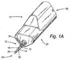
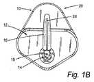
上述したさまざまな処置装置実施形態のいずれかと組み合わせて使用されるいくつかの実施形態を含む、本明細書に開示するいくつかの実施形態は、血管をシールするのに使用されるエンドエフェクタ装置に関する。1つのこうした実施形態は焼灼装置である。図1A〜図1Cは、近位端30および遠位端40を有する焼灼装置10の一実施形態を示す。図1A〜図1Cに示す焼灼装置10では、装置10は、遠位端40に双極性焼灼部12を備えた本体20を有している。 Some embodiments disclosed herein, including some embodiments used in combination with any of the various treatment device embodiments described above, relate to an end effector device used to seal a blood vessel. . One such embodiment is a cautery device. 1A-1C illustrate one embodiment of an
既知の低侵襲性生体内焼灼装置は、単極フック焼灼部を使用する。対照的に、本明細書に開示する実施形態は、より高精度でかつ周囲組織に対してより少ない損傷で血管を焼灼し切断する異なる装置を提供する。 Known minimally invasive in-vivo ablation devices use monopolar hook ablation. In contrast, the embodiments disclosed herein provide different devices that cauterize and cut blood vessels with greater accuracy and less damage to surrounding tissue.
図1A〜図1Cに最もよく示されるように、本明細書において「焼灼エンドエフェクタ」とも呼ばれる双極性焼灼部12は、固定顎部14と、血管(たとえば静脈または動脈)を留めて焼灼する可動顎部16と、焼灼された血管を切断する切断部18とを備え、したがって3機能エンドエフェクタ12を提供する。固定顎部14および可動顎部16は一対の顎のような構造となっており、固定顎部14は、焼灼プロセス中に固定されたままであり、血管を支持する実質的に剛性かつ安定した基部を提供するように構成されている。可動顎部16は、固定顎部14に対して顎のように移動することができ、それにより、可動顎部16は、固定顎部14と可動顎部16との間に配置された血管と最終的に接触して、顎14、16の間で血管を留めることができる。 As best shown in FIGS. 1A-1C, a
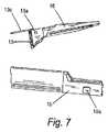
図6および図7に最もよく示されるように、一実施形態によれば、可動顎16はピボット部13をさらに備え、それは、可動顎16の近位端から側方に突出し、ピン13bを受け入れる受け口13aを有している。ピボット部13は、概して、外側シェル15の開口部内に嵌合するようにペグ状またはくさび状であり、後述するように可動顎16の移動を促進する。固定顎14は、受け口13と整列しピン13bを受け入れるように構成された開口部14aを有している。 As best shown in FIGS. 6 and 7, according to one embodiment, the
図1A〜図1Cに戻ると、固定顎部14および可動顎部16の各々は、電流源(図示せず)に接続されており、それにより、顎14、16は双極電極として機能し、電流が印加されると、一方の顎は陰極として機能し、もう一方の顎は陽極として機能する。いくつかの実施態様では、電流源は、モータに電力を供給する電気とは別個に電流を提供する発電機(図示せず)である。いくつかの実施形態では、発電機は、別個の構成要素として装置10の外側に位置している。使用時、顎14、16を流れる電気により、顎14、16間に留められた血管を焼灼する熱が発生する。いくつかの実施形態では、電流は、手術者により、たとえば発電機のボタンを押すかまたはスイッチを入れることによって別個に印加される。 Returning to FIGS. 1A-1C, each of the fixed
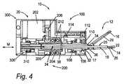
図4に最もよく示されるように、双極性焼灼エンドエフェクタ12の固定顎14はシャフト32に取り付けられており、シャフト32は、固定顎14から近位方向に延在しかつ本体20内に配置されている。切断部18は、(図1A〜図1Cおよび図4に示すように)顎14、16の間に配置され、シャフト32を通って延在している。シャフト32は溝穴39を有し、溝穴39は、シャフト32の頂部34側または底部36側のいずれかまたは両方に切り込まれ、シャフト32の長さの一部に沿って長手方向に延在して(図4に示すように)ピン38を収容し、ピン38は、溝穴39を通って延在し、切断部に結合されるように、切断部18に取り付けられるかまたはそれを通って延在している。したがって、ピン38および切断部18は一緒に、溝穴39に沿って略近位の第1位置から切断部18とともにより遠位の第2位置まで摺動することができる。図5に最もよく示されるように、いくつかの実施形態では、固定顎14および可動顎16の一方または両方はチャネル26、28を有し、チャネル26、28内で、切断部18は第1位置から第2位置まで移動する。 As best shown in FIG. 4, the fixed
図4に示す実施形態では、切断部18は、実質的に細長く、近位端24および遠位端25を有している。切断部18は、遠位端25に切断面22を有し、それにより、切断部18が略近位の第1位置からより遠位の第2位置まで移動する時、焼灼装置10の顎14、16間に封入された、焼灼された血管は、焼灼箇所で切断される。 In the embodiment shown in FIG. 4, the
説明および理解を容易にするために、本明細書に記載されているような焼灼装置10は、図2に示すように3つの部分100、200、300を有している。この実施形態では、各部分は、概して、本体20内の焼灼装置10の機能を制御するように構成された複数のコンポーネントを画定している。すなわち、第1部分100は、上述したように顎14、16への電流の印加と双極性焼灼エンドエフェクタ12の回転とを制御する。第2部分200は、切断部18の位置決めを制御する。最後に、第3部分300は、双極性焼灼エンドエフェクタ12の顎14、16の開放および閉鎖を制御する。図示される実施形態は3つの部分を利用するが、この各部分の識別および分け方は、単に説明および理解を容易にするために提供されている。これらの部分を、より多いかあるいは少ない部分となるように、結合または分割してもよいことも理解される。たとえば、第1部分100を、電流およびエンドエフェクタ回転を別個に制御する2つの部分に分割してもよい。 For ease of explanation and understanding, the
いくつかの実施形態によれば、部分は、第1部分100が双極性焼灼エンドエフェクタ12に対して近位であり、第3部分300が装置10の近位端30の最も近くに位置し、第2部分200が第1部分100と第3部分300との間に位置するように、構成されかつ配置されている。いくつかの実施形態では、それらの部分は、焼灼装置10の形状が遠位端に向かってより細くなるように構成されかつ配置されている。しかしながら、それらの部分を、装置の適切な機能に対して好適なあらゆる方法で構成するかまたは配置することができ、それらの部分は、機能的利点、審美的利点および/または製造上の利点を提供するあらゆる変更を含むことができることが理解されるべきである。こうした利点としては、限定されないが、双極性焼灼エンドエフェクタ12の可視性、サイズ低減、材料コストの低減等が挙げられる。 According to some embodiments, the portion is such that the
本明細書に記載するような装置10のさまざまな機能に関する力は、図4および図5に最もよく示されるように、モータ102、202、302によって提供される。モータ102、202、302用の電流は、電源(図示せず)によって提供される。一実施態様によれば、電源は、装置10に対して外部に配置されている。別法として、電源を装置内に配置することができる。いくつかの実施形態では、モータ102、202、302用の電源は制御装置(図示せず)も有し、制御装置は、モータ102、202、302を制御しかつ/またはモータ102、202、302の状態(たとえば位置)を検知するコンポーネントを有している。たとえば、制御装置を、使用者によって操作されるように構成された外部制御装置とすることができる。いくつかの実施形態では、モータ102、202、302用の電流源は、制御装置とは別個である。他の実施形態では、各モータ102、202、302は、互いに別個に制御されかつ/または電力が供給される。いくつかの実施形態では、モータ102、202、302用の電気は、顎14、16に提供される電流と同じ電源によって提供される。 Forces related to various functions of the
図5に最もよく示されるように、モータ102、202、302のうちの1つまたは複数は、エンコーダ、たとえば102a、302a(モータ202に対しては図示せず)を有し、それは、制御装置に接続されて、制御装置から制御命令を受け取り、制御装置にモータ102、202、302の状態に関するデータを提供する。いくつかの実施形態では、1つまたは複数のモータ102、202、302はまた、ギヤヘッド、たとえば102b、302b(モータ202に対しては図示せず)も有している。ギヤヘッド102b、302b(モータ202に対しては図示せず)は、固定式でもよいし、いくつかの実施形態では、複数の歯車比を提供するように取外し可能かつ交換可能なものとしてもよい。 As best shown in FIG. 5, one or more of the
一実施態様によれば、双極性焼灼エンドエフェクタ12の電気的性質のために、駆動系(装置の第1部分100、第2部分200および第3部分300を含む)は、モータ102、202、302によって駆動される非導電性歯車を使用することにより、モータ102、202、302から電気的に絶縁される。一実施形態では、非導電性歯車はナイロンから作製される。別法として、歯車を、歯車に使用することができるあらゆる既知の非導電性材料から作製することができる。非導電性歯車は、電流が駆動系を伝わって顎14、16まで流れ、モータ102、202、302と制御装置との間の通信に影響を与える電気的干渉をもたらすのを阻止する。いくつかの実施形態では、導電性歯車および非導電性歯車の両方が使用される。たとえば、一実施態様では、図4および図5に最もよく示されるように、歯車106、208、306は非導電性材料から作製され、歯車104、206、308は導電性材料から作製される。別の実施態様によれば、電気的干渉の影響を、非導電性歯車を使用する代りにまたはそれに加えて、制御装置またはエンコーダ102a、302aに干渉低減ソフトウェアおよび/またはコンポーネントを使用することによって低減することができる。 According to one embodiment, due to the electrical nature of the bipolar
図3Aおよび図5に最もよく示されるように、焼灼装置10の第1部分100は、双極性焼灼エンドエフェクタ12に動作可能に結合されて双極性焼灼エンドエフェクタ12の回転を制御する第1部分モータ102を含む。いくつかの実施形態では、第1部分モータ102は、双極性焼灼エンドエフェクタ12に直接結合され、または第1部分モータ102を、1つあるいは複数の結合手段によって双極性焼灼エンドエフェクタ12に間接的に結合することができる。たとえば、図3Aおよび図3Bに示す実施形態では、第1部分モータ102は、第1歯車104および第2歯車106によって双極性焼灼エンドエフェクタ12に結合されており、第2歯車106は、図5に最もよく示されるように、金属製連結器108を介して双極性焼灼エンドエフェクタ12のシャフト32に取り付けられており、それにより、第1部分モータ102によってもたらされる回転移動が、図3Aに示す軸Aを中心とする双極性焼灼エンドエフェクタ12の回転移動に伝達される。いくつかの実施形態では、金属製連結器108は、外側シェル15を介して双極性焼灼エンドエフェクタ12に結合されている。図6および図7に最もよく示されるように、外側シェル15は、金属製連結器108から遠位方向に突出し、開口部15aを有し、その開口部15aを通って、可動顎16のピボット部13が突出し、連結器108の回転移動をシャフト32に変換する。 As best shown in FIGS. 3A and 5, the
第2歯車106は、たとえば接着剤(たとえばUV硬化接着剤)を使用して、金属製連結器108に固定することができる。いくつかの実施形態では、第2歯車106および金属製連結器108は、各構成部品の形状によって第2歯車106が金属製連結器108に対して移動しないように構成されている(すなわち非円形形状)。たとえば、金属製連結器108を、第2歯車106の略正方形の穴に嵌合するように略正方形とすることができる。 The
図4に戻ると、第1部分100は、顎14、16に電流を印加するコンポーネントをさらに含む。この実施形態では、第1部分100は、可動顎16用の電気接続部110を有している。電気接続部110は、第1スリップリング112への摺動接触を可能にするように構成され、第1スリップリング112は、電流源(図示せず)に直接または間接的に接続されている。スリップリング112は略U字型またはC字型であり、それにより、電気接続部110がシャフト36とともに回転する時に電気接続部110との接触を維持する。接続部110に電気接続を提供するためにワイヤではなくスリップリング112を使用することにより、接続部110が回転する際の駆動系を中心とするワイヤのねじれが防止される。可動顎16は、図7に示すワイヤ13cのような導体または他の適切な導体を介して接続部110に電気的に接続されている。電気接続部110は、接続部110と固定顎14との間に非導電性(たとえばプラスチック)リング17を含めることにより、固定顎14から電気的に絶縁される。第1部分はまた、固定顎14に関連する第2スリップリング114も含み、それは、回転中にシャフト36との電気的接触を維持することにより、第1スリップリング112と同様に機能する。顎16、14に電流を別個に提供するスリップリング112、114の使用により、電流が印加される時に、それぞれ、一方の顎が陰極として機能し、もう一方の顎が陽極として機能することができる。いくつかの実施形態では、顎14、16間の電気的連絡を制限するかまたは集中させるように追加の構成部品または変更を含むことが望ましい場合がある。 Returning to FIG. 4, the
図4に示す実施形態の第2部分200は第2部分モータ202を含み、それは、切断部18に動作可能に結合されて、移動線Mに沿った切断部18の第1位置から第2位置までの移動を制御する。第2部分モータ202は、直接または結合手段を介して間接的にねじ切りカラー204に結合されている。図4に示す実施形態では、第2部分モータ202をねじ切りカラー204に結合する結合手段は、第2部分モータ202を第2歯車208に接続する第1歯車206を含み、第2歯車208は、上述したように、たとえば接着剤(たとえばUV硬化接着剤)または非円形形状を用いてねじ切りカラー204に取り付けられている。切断部18に取り付けられるかまたはそれを通って延在するピン38の端部は、ねじきりカラー204のねじ山212に位置し、それにより、第2部分モータ202によってもたらされる回転移動は、Mに沿ったピン38およびそれにより切断部18の側方(水平)移動に変換される。第2部分は、Mに沿った切断部18の移動が、顎14、16間に留められた血管を切断するために約1.27cm(約0.5インチ)から約2.54cm(約1.0インチ)までの範囲の距離であるように構成されている。別法として、距離は、約1.78cm(約0.7インチ)から約2.54cm(約1.0インチ)の範囲である。しかしながら、この距離は血管サイズおよび焼灼装置10の所定の構成に関して適切に調整することができる。一実施形態では、可動顎16のピボット部13は開口部を有し、切断部18は移動する時にその開口部を通過する。血管を切断するために使用されていない時、切断部18は、可動顎16を開放するかまたは閉鎖することができるように、顎14、16に近接した位置まで後退する。 The
図4および図5に示す第3部分300は、可動顎16に動作可能に結合されて顎14、16の開閉を制御する第3部分モータ302を含む。いくつかの実施形態では、第3部分モータ302は、シャフト32に直接結合されており、または第3部分モータ302を、1つあるいは複数の結合手段によってシャフト32に間接的に結合することができる。たとえば、図4および図5に示す実施形態では、第3部分モータ302は、第1歯車308および第2歯車306によってシャフト32に結合されており、第2歯車306は、たとえば接着剤(たとえばUV硬化接着剤)または非円形形状を用いてカラー310に取り付けられている。いくつかの実施形態では、シャフト32およびカラー310は、モータ302によってもたらされる回転が、Mに沿ったシャフト32およびそれにより外側シェル15に対する顎14、16の側方移動に変換されるようにねじ切りされている。図6に最もよく示されるように、開口部15aは、外側シェル15に対し、可動顎16のピボット部13がMに沿って側方に移動するのを制限し、それにより、可動顎16はMに沿ったシャフト32の側方並進により開口部15aにおいてピボット部13を介してピン13bの周囲で枢動することで、開放または閉鎖する。 The
代替実施形態では、固定顎14を、第2可動顎に置き換えることができる。この実施形態では、第2可動顎は、シャフト32に枢動可能に取り付けられ、ピボット部13と同様のピボット部を有している。この実施形態では、外側シェル15は、開口部15aに類似する第2開口部を有するように構成されており、第2開口部は、第2可動顎のピボット部の側方移動を制限し、それにより第2可動顎が、可動顎16と同様にMに沿ったシャフト32の並進を介して開閉する。 In an alternative embodiment, the fixed
第3部分300は、顎14、16の間に留められた血管の厚さを検出する手段をさらに含むことができる。血管厚さを、たとえば、可動顎16を閉鎖するために必要なMに沿ったシャフト32の側方並進の量または固定顎14に対する可動顎16の位置に基づいて、計算することができる。いくつかの実施形態では、固定顎14に対する可動顎16の位置は、たとえば、顎14、16間の電気的インピーダンスを測定することによって求められる。 The
上述したように、患者の体内で行われる処置のための装置等、小型またはより小さいサイズが望ましい装置を含む、あらゆるタイプの医療装置において、本明細書に開示する焼灼装置実施形態を利用することができる。こうした使用に対して適切な寸法の焼灼装置を達成するために、本明細書に開示するコンポーネントの寸法を、装置の全体的なサイズを制御するように調整することができる。たとえば、一実施態様では、モータ102、202、302のサイズを約8mmから約15mmの範囲とすることができ、本体の全長は約7.6cm(約3インチ)未満で維持される。幾つかの実施形態では、焼灼部の全長は約3.8cm(約1.5インチ)未満で維持される。いくつかの実施形態では、高さおよび/または幅は約5.1cm(2インチ)未満で維持される。別法として、サイズ要件、重量要件および/または可視性要件に応じて、他の寸法を使用することができる。 As described above, utilizing the ablation device embodiments disclosed herein in any type of medical device, including devices where a smaller or smaller size is desirable, such as devices for procedures performed within a patient's body. Can do. In order to achieve an appropriately dimensioned cautery device for such use, the dimensions of the components disclosed herein can be adjusted to control the overall size of the device. For example, in one embodiment, the size of the
使用時、焼灼装置20は、関節ロボットアーム等、別の場所に記載されているような相補的システムまたは装置を用いて標的血管に隣接して配置される。次に、焼灼装置20は、以下のように動作して血管を焼灼する。第1部分モータ102により焼灼エンドエフェクタ12を回転させ、顎14、16が血管を封入することができるように顎を血管と整列させて位置決めする。第3部分モータ302により可動顎16を開放するように作動させ、焼灼エンドエフェクタ12を、血管が顎14、16の間に位置するように配置する。そして、第3部分モータ302により可動顎16を、顎14、16の間に血管が配置された状態で閉鎖するように作動させ、電流源(図示せず)によって顎14、16を介して血管に電流を印加し、それにより血管を焼灼する。第2部分モータ202により切断部18を焼灼装置20の遠位端に向かって駆動して切断面22を顎14、16に封入された血管に押し通し、それによって血管を切断する。 In use, the
図8A〜図22は、上述したような種々の医療装置のうちのいずれか1つに組み込むことができるデュアルエンドエフェクタ操作コンポーネント410を示す。この実施形態では、デュアルエンドエフェクタ操作コンポーネント410は、ロボットアーム412の端部に配置されている。ロボットアーム412は、生体内装置等のあらゆるロボット医療装置の一部であり得ることがさらに理解される。図8A〜図10Bに最もよく示されるように、アーム412は、第1アームセグメント(または「上腕」)412Aおよび第2アームセグメント(または「前腕」)412Bを含む2つのアームセグメントを有している。第1アームセグメント412Aは、継手またはヒンジ(図示せず)を介して胴部モータハウジング414に回転可能に連結されている。胴部モータハウジング414は、第1アームセグメント412Aの胴部モータハウジング414に対する回転を提供するモータおよび作動機構(図示せず)を収容している。さらに、第1アームセグメント412Aは、継手416Aにおいて第2アームセグメント412Bに回転可能に連結され、第2アームセグメント412Bは、継手416Bにおいてデュアルエンドエフェクタ操作コンポーネント410に回転可能に連結されている。 8A-22 illustrate a dual end
一実施形態では、デュアルエンドエフェクタ操作コンポーネント410は、アクチュエータハウジング418およびエンドエフェクタハウジング420を有している。エンドエフェクタハウジング420は2つのエンドエフェクタ要素422、424を有している。図8A〜図10Bに示す実施形態では、一方のエンドエフェクタ要素は焼灼部422であり、第2のエンドエフェクタ要素は把持具424である。別法として、デュアルエンドエフェクタ操作コンポーネント410のエンドエフェクタ要素は、医療装置で使用されるあらゆる既知のエンドエフェクタとすることができ、たとえば鉗子、持針器、はさみ、Ligasure(登録商標)またはメス部材等が挙げられる。 In one embodiment, the dual end
図8Aおよび図8Bに最もよく示されるように、一実施形態では、両エンドエフェクタ要素422、424は動作可能なままであるが、エンドエフェクタハウジング420は、把持具424が対象組織にアクセス可能でありかつ医療処置を行うことができるように方向付けられている。 As best shown in FIGS. 8A and 8B, in one embodiment, both
図9Aおよび図9Bに最もよく示されるように、別の実施形態では、両エンドエフェクタ要素422、424は動作可能なままであるが、エンドエフェクタハウジング420は、焼灼部422が対象組織にアクセス可能でありかつ医療処置を行うことができるように方向付けられている。 As best shown in FIGS. 9A and 9B, in another embodiment, both
一実施形態では、両エンドエフェクタ要素422、424は、エンドエフェクタハウジング420に対して回転することができる。より詳細には、図9Aに最もよく示されるように、焼灼部422は、矢印AAで示されるように、線Aによって示される軸を中心にエンドエフェクタハウジング420に対して回転可能である。さらに、把持具424は、矢印BBで示されるように、線Bによって示される軸を中心にエンドエフェクタハウジング420に対して回転可能である。一実施形態によれば、把持具424はまた、開放形態と閉鎖形態(図示せず)との間で移動するようにも構成されている。代替実施形態(図示せず)では、両エンドエフェクタ要素422、424は、エンドエフェクタハウジング420に対して回転することができ、かつ両エンドエフェクタ要素422、424を、エンドエフェクタのタイプに応じて、開放形態と閉鎖形態との間で移動するように構成することができる。別の代替実施形態では、両エンドエフェクタを、開放位置と閉鎖位置との間で移動するように構成することができるように、2つのエンドエフェクタを互いに動作可能に結合することができる。 In one embodiment, both
図10Aに最もよく示されるように、一実施形態では、デュアルエンドエフェクタ操作コンポーネント410を、継手416Bと第2アームセグメント412Bに収容されている作動モータおよび歯車システム(図示せず)とを介して、第2アームセグメント412Bに対して回転させることができる。 As best shown in FIG. 10A, in one embodiment, the dual end
図10Bに最もよく示されるように、一実施形態では、デュアルエンドエフェクタ操作コンポーネント410および第2アームセグメント412Bを、継手416Aと第1アームセグメント412A内の作動モータおよび歯車システム(図示せず)とを介して、第1アームセグメント412Aに対して回転させることができる。 As best shown in FIG. 10B, in one embodiment, the dual end
図11A〜図12Bに最もよく示されるように、デュアルエンドエフェクタ410内では、前腕歯車ハウジング426は、駆動軸430に強固に結合されている作動モータ428を収容している。駆動軸430は、回転モータ平歯車432に強固に結合されている。回転モータ平歯車432は、第2アームセグメント(たとえば、図8A〜図10Bに示すような第2アームセグメント412B等)に強固に結合されている回転歯車434に回転可能に連結されている。作動モータ428の作動により、駆動軸430および回転モータ平歯車432が回転する。回転モータ平歯車432の回転により、デュアルエンドエフェクタ操作コンポーネント410が第2アームセグメント(第2アームセグメント412B等)に対して回転する。 As best shown in FIGS. 11A-12B, within the
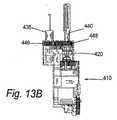
図13Aおよび図13Bに最もよく示されるように、一実施形態では、焼灼部422は、遠位焼灼先端部438に強固に取り付けられている近位焼灼ハウジング436を有している。一実施形態では、焼灼先端部438に電気を供給するワイヤ(図示せず)は、焼灼ハウジング436に封入されている。ワイヤは、デュアルエンドエフェクタ操作コンポーネント410を通って近位方向に伸びており、標準電気焼灼発電機(図示せず)等の電源にワイヤの近位端において結合されている。別の実施形態では、電源を、デュアルエンドエフェクタ操作コンポーネント410内に配置することができる。図示するような実施態様によれば、把持具424は、2つの把持要素442、444に結合された近位把持具ハウジング440を有している。 As best shown in FIGS. 13A and 13B, in one embodiment, the
図13Bに最もよく示されるように、一実施形態では、焼灼ハウジング436は、エンドエフェクタハウジング420内の焼灼回転歯車446に強固に結合されている。さらに、把持具ハウジング440は、エンドエフェクタハウジング420内の把持具回転平歯車448に強固に接続されている。 As best shown in FIG. 13B, in one embodiment, the
図14に最もよく示されるように、焼灼回転歯車446は、回転モータ平歯車450に回転可能に連結されている。回転モータ平歯車450は、回転モータ452とモータ452に結合された回転モータギヤヘッド454とによって回転可能に駆動される。回転モータ452および回転モータギヤヘッド454の作動により、回転モータ平歯車450が回転し、したがって焼灼回転歯車446および焼灼ハウジング436が回転する。焼灼ハウジング436は、焼灼回転歯車446に対して近位の2つの軸受要素456、458、すなわち遠位軸受456および近位軸受458にさらに結合されており、それらはともに、焼灼ハウジング436を支持しかつその回転摩擦を低減する。焼灼ハウジング436および近位軸受458は焼灼ハウジング予荷重ナット460にさらに結合されており、焼灼ハウジング予荷重ナット460は、焼灼ハウジング436の並進を制限し、2つの軸受要素456、458に対する予荷重または締付力を提供して、回転中に軸受要素456、458を適所に保持することにより、焼灼ハウジング436の回転中の摩擦を低減するのに役立つ。 As best shown in FIG. 14, the
一実施形態では、把持具回転平歯車448は、回転モータ平歯車450に回転可能に連結されている。回転モータ452および回転モータギヤヘッド454の作動により、回転モータ平歯車450が回転し、したがって、焼灼ハウジング436の回転と同時に把持具回転平歯車448および把持具ハウジング440が回転する。 In one embodiment, the gripper
一実施形態では、把持具回転平歯車448の近位において、把持具ハウジング440は2つの勾配座金要素、すなわち遠位勾配座金要素462および近位勾配座金要素464に結合されており、それらは、把持具に対するコンプライアンスを提供するとともに、把持具ハウジング440の回転中に移動部品間の接触を防止する。把持具ハウジング440は、2つの軸受要素、すなわち遠位軸受466および近位軸受468にさらに結合されており、それらは、把持具ハウジング440に対する支持を提供するとともに把持具ハウジング440の回転摩擦を低減する。把持具ハウジング440は遠位六角予荷重ナット470にさらに結合されており、遠位六角予荷重ナット470は、把持具ハウジング440の並進を低減し、軸受466、468に対する予荷重または締付力を提供して、回転中に軸受466、468を適所に保持することにより把持具ハウジング440の回転中の摩擦を低減するのに役立つ。 In one embodiment, proximal to the gripper
一実施形態では、作動モータ472は、2つの作動モータ取付ボルト476、478によって作動モータハウジング474に強固に結合されている。作動モータ取付ボルト476、478は、作動モータ472の作動モータハウジング474への並進および回転運動を抑制する。 In one embodiment, the
図15に最もよく示されるように、一実施形態では、作動モータ472は作動モータ平歯車480に強固に結合されている。作動モータ472の作動により作動モータ平歯車480が回転し、この回転は、駆動軸ハウジング平歯車482に変換される。 As best shown in FIG. 15, in one embodiment, the
図16に最もよく示されるように、駆動軸ハウジング平歯車482は駆動軸ハウジング484に強固に結合されており、駆動軸ハウジング484はさらに、把持具駆動軸486に回転可能に連結されている。したがって、作動モータ472および作動モータ平歯車480の作動を介する駆動軸ハウジング平歯車482の回転により、駆動軸ハウジング484が回転する。そして、駆動軸ハウジング484の回転により把持具駆動軸486が並進する。 As best shown in FIG. 16, the drive shaft
一実施形態では、駆動軸ハウジング484の回転は、近位六角予荷重ナット488、いくつかの勾配座金要素490、492、494および軸受要素496、498によって促進される。駆動軸ハウジング484は、駆動軸ハウジングねじ500にさらに強固に結合されており、駆動軸ハウジングねじ500は、駆動軸ハウジング484の近位軸受498への並進を抑制する。 In one embodiment, rotation of the
図17に最もよく示されるように、把持具回転ピン502は、把持具ハウジング440の1つの側面を貫通し、把持要素442、444の各々の穴を通してねじ込まれ、把持具ハウジング440の反対側の側面に強固に結合される。把持具駆動軸486が、駆動軸ハウジング484の回転を介して並進する際(図16に最もよく示されるように)、把持具駆動軸486を把持具要素442、444に接続するコネクタピン504は、把持具要素442、444の溝内で上下に摺動する。この並進により、さらに把持具要素442、444が開閉する。 As best shown in FIG. 17, the
図18および図19に最もよく示されるように、焼灼部442は、所望のエンドエフェクタ要素の動作およびアクセス可能性の必要に応じて伸長および収縮することができる。図18に最もよく示されるように、焼灼部422を、把持具424の動作中に伸縮式焼灼シャフト506の収縮によって収縮させることができ、それにより、焼灼部422による組織との望ましくない接触を避けることができる。図19に最もよく示されるように、焼灼部422の動作中、焼灼部422を、伸縮式焼灼シャフト506の伸長によって把持具424の近位先端部を越えて伸長させることができる。 As best shown in FIGS. 18 and 19, the
図20および図21に最もよく示されるように、焼灼部422は、回転モータ平歯車450の回転によって伸長および収縮する。回転モータ平歯車450は、上部長尺焼灼シャフト508に回転可能に連結されている。上部長尺焼灼シャフト508は、止めねじ512を介して下部長尺焼灼シャフト510に強固に結合されている。下部長尺焼灼シャフト510は、2つの軸受要素514、516によって支持されている。下部長尺焼灼シャフト510は、伸縮式焼灼シャフト506に回転可能に連結されている。 As best shown in FIGS. 20 and 21, the
図22に最もよく示されるように、下部長尺焼灼シャフト510(図20および図21に示す)の回転により、伸縮式焼灼シャフト506は、伸縮式焼灼シャフト506の雄ねじ切りとねじきり焼灼通電リング518の雌ねじ切りとを介して、収縮または伸長する。伸縮式焼灼シャフト506の雄ねじ切りにより、伸縮式焼灼シャフト506は、下部長尺焼灼シャフト510(図20および図21に示す)が回転する時に上下に並進する。電力は、通電リング518に接続されたワイヤ(図示せず)を介して焼灼部422に供給される。 As best shown in FIG. 22, with the rotation of the lower long cautery shaft 510 (shown in FIGS. 20 and 21), the
本発明を、好ましい実施形態に関して説明したが、当業者は、本発明の趣旨および範囲から逸脱することなく形態および細部に変更を行うことができることを理解するであろう。 Although the present invention has been described with reference to preferred embodiments, workers skilled in the art will recognize that changes may be made in form and detail without departing from the spirit and scope of the invention.
Claims (12)
Translated fromJapanese(a)生体内ロボット装置のアームに動作可能に結合された生体内エンドエフェクタ本体であって、前記アームおよび前記エンドエフェクタ本体は完全に患者の体腔内に配置されるように構成されており、
(i)焼灼部作動モータ、
(ii)切断部作動モータ、
(iii)顎作動モータ、
(iv)前記エンドエフェクタ本体内に配置されかつ前記顎作動モータに動作可能に結合された焼灼部シャフト、
(v)前記焼灼部シャフトに回転可能に取り付けられた電気接続部、および
(vi)前記焼灼部シャフトの回転中に前記電気接続部との電気的接触を維持するように構成された第1スリップリング
を備えるエンドエフェクタ本体と、
(b)前記エンドエフェクタ本体に動作可能に結合された双極性血管焼灼部であって、
(i)前記焼灼部シャフトの遠位端に結合された固定顎、
(ii)前記焼灼部シャフトの前記遠位端に枢動可能に連結された可動顎、および
(iii)前記切断部作動モータに動作可能に結合された切断部
を備え、
前記焼灼部が前記焼灼部作動モータに動作可能に結合されており、
前記電気接続部が前記可動顎および前記固定顎のうちの一方に電気的に接続されている、焼灼部、および
(c)前記第1スリップリングに電気的に接続された外部電源
を備える、シールエンドエフェクタ。An in vivo vascular sealend effector , wherein the sealend effector comprises:
(A)an in-vivo end effector bodyoperatively coupled to an arm of an in-vivo robotic device ,wherein the arm and the end effector body are configured to be completely disposed within a patient's body cavity;
(I) ablation unit operation motor,
(Ii) cutting section operating motor,
(Iii) jaw operating motor,
(Iv) an ablation shaft disposed within theend effector body and operatively coupled to the jaw actuation motor;
(V) an electrical connection rotatably attached to the ablation shaft; and
(Vi) anend effector body comprising afirst slip ring configured to maintain electrical contact with the electrical connection during rotation of the cautery shaft ;
(B) a bipolar vessel ablation portion operatively coupled to theend effector body,
(I) a fixed jaw coupled to the distal end of the cautery shaft;
(Ii) Preparationsexample the said distal end pivotally coupled to a movable jaw of the ablation section shaft, and (iii) the cutting part cutting portion operatively coupled to the actuationmotor,
The ablation part is operably coupled to the ablation part actuating motor;
Acautery portion,wherein the electrical connection is electrically connected to one of the movable jaw and the fixed jaw, and
(C) an external power source electrically connected to the first slip ring
A sealend effector comprising:
(i)焼灼部作動モータ、
(ii)切断部作動モータ、
(iii)顎作動モータ、
(iv)前記エンドエフェクタ本体内に配置されかつ前記顎作動モータに動作可能に結合された焼灼部シャフト、
(v)前記焼灼部シャフトに回転可能に取り付けられた電気接続部、および
(vi)前記焼灼部シャフトの回転中に前記電気接続部との電気的接触を維持するように構成された第1スリップリング
を備える、生体内ロボット装置。An in- vivo robotic devicecomprising anarm operably coupled to anend effector body ,wherein the arm and the end effector body are configured to be completely disposed within a body cavity of a patient, the end effector body Is
(I) ablation unit operation motor,
(Ii) cutting section operating motor,
(Iii) jaw operating motor,
(Iv) an ablation shaft disposed within the end effector body and operatively coupled to the jaw actuation motor;
(V) an electrical connection rotatably attached to the ablation shaft; and
(Vi) a first slip ring configured to maintain electrical contact with the electrical connection during rotation of the cautery shaft.
An in- vivo robot device comprising:
(b)前記カラーの回転により、後退位置と展開位置との間での前記切断部の軸方向の移動をもたらすように、前記切断部に固定され、かつ前記カラーに動作可能に結合された変換ピン(B) a transformation fixed to the cutting portion and operably coupled to the collar so that rotation of the collar causes an axial movement of the cutting portion between a retracted position and a deployed position. pin
を更に備える、請求項1に記載のシールエンドエフェクタ。The seal end effector of claim 1, further comprising:
(a)前記切断部作動モータに回転可能に結合された第1ねじ切りカラー、および(A) a first threaded collar rotatably coupled to the cutting section actuation motor; and
(b)前記第1ねじ切りカラーの回転により、後退位置と展開位置との間での前記切断部の軸方向の移動をもたらすように、前記切断部に固定され、かつ前記第1ねじ切りカラーに螺合された変換ピン(B) The first threading collar is fixed to the cutting part and screwed onto the first threading collar so as to cause an axial movement of the cutting part between a retracted position and a deployed position by rotation of the first threading collar. Combined conversion pin
を更に備える、請求項1に記載のシールエンドエフェクタ。The seal end effector of claim 1, further comprising:
Applications Claiming Priority (5)
| Application Number | Priority Date | Filing Date | Title |
|---|---|---|---|
| US201161495487P | 2011-06-10 | 2011-06-10 | |
| US61/495,487 | 2011-06-10 | ||
| US201161498919P | 2011-06-20 | 2011-06-20 | |
| US61/498,919 | 2011-06-20 | ||
| PCT/US2012/041911WO2013048595A1 (en) | 2011-06-10 | 2012-06-11 | Methods, systems, and devices relating to surgical end effectors |
Publications (2)
| Publication Number | Publication Date |
|---|---|
| JP2014523769A JP2014523769A (en) | 2014-09-18 |
| JP6174017B2true JP6174017B2 (en) | 2017-08-02 |
Family
ID=47677994
Family Applications (1)
| Application Number | Title | Priority Date | Filing Date |
|---|---|---|---|
| JP2014514927AActiveJP6174017B2 (en) | 2011-06-10 | 2012-06-11 | In vivo vascular seal end effector and in vivo robotic device |
Country Status (5)
| Country | Link |
|---|---|
| US (6) | US9060781B2 (en) |
| EP (4) | EP2717796B1 (en) |
| JP (1) | JP6174017B2 (en) |
| CA (1) | CA2838637C (en) |
| WO (1) | WO2013048595A1 (en) |
Families Citing this family (53)
| Publication number | Priority date | Publication date | Assignee | Title |
|---|---|---|---|---|
| US7960935B2 (en) | 2003-07-08 | 2011-06-14 | The Board Of Regents Of The University Of Nebraska | Robotic devices with agent delivery components and related methods |
| US9579088B2 (en) | 2007-02-20 | 2017-02-28 | Board Of Regents Of The University Of Nebraska | Methods, systems, and devices for surgical visualization and device manipulation |
| US8679096B2 (en) | 2007-06-21 | 2014-03-25 | Board Of Regents Of The University Of Nebraska | Multifunctional operational component for robotic devices |
| WO2007149559A2 (en) | 2006-06-22 | 2007-12-27 | Board Of Regents Of The University Of Nebraska | Magnetically coupleable robotic devices and related methods |
| US8343171B2 (en) | 2007-07-12 | 2013-01-01 | Board Of Regents Of The University Of Nebraska | Methods and systems of actuation in robotic devices |
| JP2010536435A (en) | 2007-08-15 | 2010-12-02 | ボード オブ リージェンツ オブ ザ ユニバーシティ オブ ネブラスカ | Medical inflation, attachment and delivery devices and associated methods |
| CA2695619C (en) | 2007-08-15 | 2015-11-24 | Board Of Regents Of The University Of Nebraska | Modular and cooperative medical devices and related systems and methods |
| WO2011075693A1 (en) | 2009-12-17 | 2011-06-23 | Board Of Regents Of The University Of Nebraska | Modular and cooperative medical devices and related systems and methods |
| EP2600758A1 (en) | 2010-08-06 | 2013-06-12 | Board of Regents of the University of Nebraska | Methods and systems for handling or delivering materials for natural orifice surgery |
| WO2012047939A2 (en)* | 2010-10-04 | 2012-04-12 | Ind Platforms Llc | Expandable devices, rail systems, and motorized devices |
| JP6174017B2 (en) | 2011-06-10 | 2017-08-02 | ボード オブ リージェンツ オブ ザ ユニバーシティ オブ ネブラスカ | In vivo vascular seal end effector and in vivo robotic device |
| WO2013009887A1 (en) | 2011-07-11 | 2013-01-17 | Board Of Regents Of The University Of Nebraska | Robotic surgical devices, systems and related methods |
| WO2013052137A2 (en) | 2011-10-03 | 2013-04-11 | Board Of Regents Of The University Of Nebraska | Robotic surgical devices, systems and related methods |
| WO2013106569A2 (en) | 2012-01-10 | 2013-07-18 | Board Of Regents Of The University Of Nebraska | Methods, systems, and devices for surgical access and insertion |
| US10179033B2 (en) | 2012-04-26 | 2019-01-15 | Bio-Medical Engineering (HK) Limited | Magnetic-anchored robotic system |
| US8891924B2 (en) | 2012-04-26 | 2014-11-18 | Bio-Medical Engineering (HK) Limited | Magnetic-anchored robotic system |
| EP2844181B1 (en) | 2012-05-01 | 2021-03-10 | Board of Regents of the University of Nebraska | Single site robotic device and related systems |
| EP3189948B1 (en) | 2012-06-22 | 2018-10-17 | Board of Regents of the University of Nebraska | Local control robotic surgical devices |
| RU2686954C2 (en)* | 2012-06-28 | 2019-05-06 | Конинклейке Филипс Н.В. | Navigation by optical fiber sensor for visualization and monitoring of vessels |
| EP2882331A4 (en) | 2012-08-08 | 2016-03-23 | Univ Nebraska | ROBOTIC SURGICAL SYSTEMS AND DEVICES, AND ASSOCIATED METHODS |
| US12295680B2 (en) | 2012-08-08 | 2025-05-13 | Board Of Regents Of The University Of Nebraska | Robotic surgical devices, systems and related methods |
| US9770305B2 (en) | 2012-08-08 | 2017-09-26 | Board Of Regents Of The University Of Nebraska | Robotic surgical devices, systems, and related methods |
| US20140066900A1 (en)* | 2012-09-06 | 2014-03-06 | Corindus, Inc. | System for guide catheter control |
| CA2905948C (en) | 2013-03-14 | 2022-01-11 | Board Of Regents Of The University Of Nebraska | Methods, systems, and devices relating to robotic surgical devices, end effectors, and controllers |
| CA2906672C (en) | 2013-03-14 | 2022-03-15 | Board Of Regents Of The University Of Nebraska | Methods, systems, and devices relating to force control surgical systems |
| CA2906772C (en)* | 2013-03-15 | 2021-09-21 | Board Of Regents Of The University Of Nebraska | Robotic surgical devices, systems and related methods |
| US10966700B2 (en) | 2013-07-17 | 2021-04-06 | Virtual Incision Corporation | Robotic surgical devices, systems and related methods |
| CA2961213A1 (en) | 2014-09-12 | 2016-03-17 | Board Of Regents Of The University Of Nebraska | Quick-release end effectors and related systems and methods |
| EP3217890B1 (en) | 2014-11-11 | 2020-04-08 | Board of Regents of the University of Nebraska | Robotic device with compact joint design |
| WO2016133631A1 (en) | 2015-02-16 | 2016-08-25 | Covidien Lp | Robotic surgical assemblies and electrosurgical instruments thereof |
| WO2017024081A1 (en) | 2015-08-03 | 2017-02-09 | Board Of Regents Of The University Of Nebraska | Robotic surgical devices systems and related methods |
| CN108289713B (en)* | 2015-09-25 | 2021-07-27 | 柯惠Lp公司 | Robotic surgical components and their electromechanical instruments |
| US20170258519A1 (en) | 2016-03-10 | 2017-09-14 | RELIGN Corporation | Arthroscopic devices and methods |
| US11207119B2 (en) | 2016-03-11 | 2021-12-28 | RELIGN Corporation | Arthroscopic devices and methods |
| US10595889B2 (en) | 2016-04-11 | 2020-03-24 | RELIGN Corporation | Arthroscopic devices and methods |
| US11172953B2 (en) | 2016-04-11 | 2021-11-16 | RELIGN Corporation | Arthroscopic devices and methods |
| CA3024623A1 (en) | 2016-05-18 | 2017-11-23 | Virtual Incision Corporation | Robotic surgical devices, systems and related methods |
| WO2018008106A1 (en)* | 2016-07-06 | 2018-01-11 | オリンパス株式会社 | Medical instrument holding device, medical system, medical instrument holding device operating method, and medical system operating method |
| CA3034671A1 (en) | 2016-08-25 | 2018-03-01 | Shane Farritor | Quick-release tool coupler and related systems and methods |
| WO2018045036A1 (en)* | 2016-08-30 | 2018-03-08 | Board Of Regents Of The University Of Nebraska | Robotic device with compact joint design and an additional degree of freedom and related systems and methods |
| CN115337111B (en) | 2016-11-22 | 2025-04-25 | 内布拉斯加大学董事会 | Improved coarse positioning device and related system and method |
| CN115553922A (en) | 2016-11-29 | 2023-01-03 | 虚拟切割有限公司 | User controller with user presence detection and related systems and methods |
| US10717166B2 (en)* | 2016-12-02 | 2020-07-21 | General Electric Company | Motorized apparatus for use with rotary machines |
| WO2018112199A1 (en) | 2016-12-14 | 2018-06-21 | Virtual Incision Corporation | Releasable attachment device for coupling to medical devices and related systems and methods |
| JP2020534931A (en)* | 2017-09-26 | 2020-12-03 | リライン コーポレーション | Arthroscopic device and method |
| CN117017492A (en)* | 2017-09-27 | 2023-11-10 | 虚拟切割有限公司 | Robotic surgical device with tracking camera technology and related systems and methods |
| WO2019089305A1 (en)* | 2017-10-30 | 2019-05-09 | Ethicon Llc | Surgical suturing instrument configured to manipulate tissue using mechanical and electrical power |
| CA3087672A1 (en) | 2018-01-05 | 2019-07-11 | Board Of Regents Of The University Of Nebraska | Single-arm robotic device with compact joint design and related systems and methods |
| CN108742782B (en)* | 2018-04-09 | 2022-05-31 | 杭州康亚医疗器械有限公司 | Multifunctional surgical grasping forceps for laparoscopy |
| WO2020146348A1 (en) | 2019-01-07 | 2020-07-16 | Virtual Incision Corporation | Robotically assisted surgical system and related devices and methods |
| WO2020261208A2 (en)* | 2019-06-28 | 2020-12-30 | Auris Health, Inc. | Patient introducer for a robotic system |
| JP2023532977A (en) | 2020-07-06 | 2023-08-01 | バーチャル インシジョン コーポレイション | Surgical robotic positioning system and related apparatus and methods |
| GB2599101B (en)* | 2020-09-23 | 2025-02-12 | Cmr Surgical Ltd | Arrangement of end effector elements |
Family Cites Families (470)
| Publication number | Priority date | Publication date | Assignee | Title |
|---|---|---|---|---|
| US3870264A (en) | 1973-03-26 | 1975-03-11 | William I Robinson | Stand |
| DE2339827B2 (en) | 1973-08-06 | 1977-02-24 | A6 In 3-02 | DENTAL EQUIPMENT |
| JPS5115425A (en) | 1974-07-29 | 1976-02-06 | Yashica Co Ltd | DENJIRERIIZUSHIKISUCHIIRUKAMERANIOKERU MOOTADORAIBUSOCHI |
| US4258716A (en) | 1978-02-06 | 1981-03-31 | The University Of Melbourne | Microsurgical instruments |
| JPS5519124A (en) | 1978-07-27 | 1980-02-09 | Olympus Optical Co | Camera system for medical treatment |
| US4246661A (en) | 1979-03-15 | 1981-01-27 | The Boeing Company | Digitally-controlled artificial hand |
| JPS58132490A (en) | 1982-01-29 | 1983-08-06 | 株式会社日立製作所 | Angle transmission mechanism |
| JPS5959371A (en) | 1982-09-30 | 1984-04-05 | フアナツク株式会社 | Industrial robot |
| US5307447A (en) | 1982-10-29 | 1994-04-26 | Kabushiki Kaisha Toshiba | Control system of multi-joint arm robot apparatus |
| GB2130889B (en) | 1982-11-26 | 1986-06-18 | Wolf Gmbh Richard | Rectoscope |
| JPS6076986A (en) | 1983-09-30 | 1985-05-01 | 株式会社東芝 | Robot |
| DE3337797C1 (en) | 1983-10-18 | 1985-04-11 | Jean Walterscheid Gmbh, 5204 Lohmar | Pull lock that can be locked in open position |
| DE3536747A1 (en) | 1984-10-15 | 1986-04-24 | Tokico Ltd., Kawasaki, Kanagawa | Joint mechanism |
| DE3525806A1 (en) | 1985-07-19 | 1987-01-29 | Kuka Schweissanlagen & Roboter | TRANSMISSION HEAD FOR MANIPULATORS |
| JPS6268293A (en) | 1985-09-20 | 1987-03-28 | 株式会社明電舎 | Manipulator shoulder mechanism |
| DE3545068A1 (en) | 1985-12-19 | 1987-06-25 | Kuka Schweissanlagen & Roboter | TRANSMISSION HEAD FOR MANIPULATORS |
| DE3612498A1 (en) | 1986-04-14 | 1987-10-29 | Norske Stats Oljeselskap | SELF-DRIVING VEHICLE FOR PIPELINES |
| US4787270A (en) | 1987-02-11 | 1988-11-29 | Cincinnati Milacron Inc. | Robotic manipulator |
| JP2591968B2 (en) | 1987-12-28 | 1997-03-19 | 株式会社日立製作所 | Industrial robot wrist |
| US5187796A (en) | 1988-03-29 | 1993-02-16 | Computer Motion, Inc. | Three-dimensional vector co-processor having I, J, and K register files and I, J, and K execution units |
| US5019968A (en) | 1988-03-29 | 1991-05-28 | Yulan Wang | Three-dimensional vector processor |
| US5108140A (en) | 1988-04-18 | 1992-04-28 | Odetics, Inc. | Reconfigurable end effector |
| US4896015A (en) | 1988-07-29 | 1990-01-23 | Refractive Laser Research & Development Program, Ltd. | Laser delivery system |
| US4897014A (en) | 1988-09-06 | 1990-01-30 | Harbor Branch Oceanographic Institution, Inc. | Device for interchange of tools |
| US5271384A (en) | 1989-09-01 | 1993-12-21 | Mcewen James A | Powered surgical retractor |
| US5201325A (en) | 1989-09-01 | 1993-04-13 | Andronic Devices Ltd. | Advanced surgical retractor |
| US5562448A (en) | 1990-04-10 | 1996-10-08 | Mushabac; David R. | Method for facilitating dental diagnosis and treatment |
| JP2914388B2 (en) | 1990-04-17 | 1999-06-28 | 株式会社ユアサコーポレーション | Polymer solid electrolyte |
| IT1241621B (en) | 1990-10-04 | 1994-01-25 | Comau Spa | ARTICULATED ROBOT |
| IT1241622B (en) | 1990-10-04 | 1994-01-25 | Comau Spa | ROBOT WRIST |
| JPH04144533A (en) | 1990-10-05 | 1992-05-19 | Olympus Optical Co Ltd | Endoscope |
| US5176649A (en) | 1991-01-28 | 1993-01-05 | Akio Wakabayashi | Insertion device for use with curved, rigid endoscopic instruments and the like |
| US5217003A (en) | 1991-03-18 | 1993-06-08 | Wilk Peter J | Automated surgical system and apparatus |
| US5172639A (en) | 1991-03-26 | 1992-12-22 | Gas Research Institute | Cornering pipe traveler |
| US5632761A (en) | 1991-05-29 | 1997-05-27 | Origin Medsystems, Inc. | Inflatable devices for separating layers of tissue, and methods of using |
| JP3307392B2 (en) | 1991-05-29 | 2002-07-24 | オリジン・メドシステムズ・インク | Endoscope retraction device for surgery |
| US5370134A (en) | 1991-05-29 | 1994-12-06 | Orgin Medsystems, Inc. | Method and apparatus for body structure manipulation and dissection |
| US5417210A (en) | 1992-05-27 | 1995-05-23 | International Business Machines Corporation | System and method for augmentation of endoscopic surgery |
| JPH05184535A (en)* | 1991-07-24 | 1993-07-27 | Olympus Optical Co Ltd | Multifunctional treating-implement |
| US5284096A (en) | 1991-08-06 | 1994-02-08 | Osaka Gas Company, Limited | Vehicle for use in pipes |
| US5674030A (en) | 1991-08-27 | 1997-10-07 | Sika Equipment Ag. | Device and method for repairing building branch lines in inacessible sewer mains |
| JP2526537B2 (en) | 1991-08-30 | 1996-08-21 | 日本電装株式会社 | Pipe energy supply system |
| JPH05115425A (en) | 1991-10-25 | 1993-05-14 | Olympus Optical Co Ltd | Endoscope |
| CA2128606C (en) | 1992-01-21 | 2008-07-22 | Philip S. Green | Teleoperator system and method with telepresence |
| US5631973A (en) | 1994-05-05 | 1997-05-20 | Sri International | Method for telemanipulation with telepresence |
| US6731988B1 (en) | 1992-01-21 | 2004-05-04 | Sri International | System and method for remote endoscopic surgery |
| US5624380A (en) | 1992-03-12 | 1997-04-29 | Olympus Optical Co., Ltd. | Multi-degree of freedom manipulator |
| US5263382A (en) | 1992-04-13 | 1993-11-23 | Hughes Aircraft Company | Six Degrees of freedom motion device |
| US5297443A (en) | 1992-07-07 | 1994-03-29 | Wentz John D | Flexible positioning appendage |
| US5762458A (en) | 1996-02-20 | 1998-06-09 | Computer Motion, Inc. | Method and apparatus for performing minimally invasive cardiac procedures |
| US5754741A (en) | 1992-08-10 | 1998-05-19 | Computer Motion, Inc. | Automated endoscope for optimal positioning |
| US5657429A (en) | 1992-08-10 | 1997-08-12 | Computer Motion, Inc. | Automated endoscope system optimal positioning |
| US7074179B2 (en) | 1992-08-10 | 2006-07-11 | Intuitive Surgical Inc | Method and apparatus for performing minimally invasive cardiac procedures |
| US5515478A (en) | 1992-08-10 | 1996-05-07 | Computer Motion, Inc. | Automated endoscope system for optimal positioning |
| US5524180A (en) | 1992-08-10 | 1996-06-04 | Computer Motion, Inc. | Automated endoscope system for optimal positioning |
| US5588442A (en) | 1992-08-12 | 1996-12-31 | Scimed Life Systems, Inc. | Shaft movement control apparatus and method |
| US5458131A (en) | 1992-08-25 | 1995-10-17 | Wilk; Peter J. | Method for use in intra-abdominal surgery |
| US5297536A (en) | 1992-08-25 | 1994-03-29 | Wilk Peter J | Method for use in intra-abdominal surgery |
| US5769640A (en) | 1992-12-02 | 1998-06-23 | Cybernet Systems Corporation | Method and system for simulating medical procedures including virtual reality and control method and system for use therein |
| US5353807A (en) | 1992-12-07 | 1994-10-11 | Demarco Thomas J | Magnetically guidable intubation device |
| CA2112271A1 (en) | 1992-12-28 | 1994-06-29 | Kiichi Suyama | Intrapipe work robot apparatus and method of measuring position of intrapipe work robot |
| EP0683684B1 (en) | 1993-01-07 | 2001-08-08 | Medical Innovations Corporation | Gastrostomy catheter system |
| US5462546A (en) | 1993-02-05 | 1995-10-31 | Everest Medical Corporation | Bipolar electrosurgical forceps |
| US6346074B1 (en) | 1993-02-22 | 2002-02-12 | Heartport, Inc. | Devices for less invasive intracardiac interventions |
| US6832996B2 (en) | 1995-06-07 | 2004-12-21 | Arthrocare Corporation | Electrosurgical systems and methods for treating tissue |
| US5363935A (en) | 1993-05-14 | 1994-11-15 | Carnegie Mellon University | Reconfigurable mobile vehicle with magnetic tracks |
| US5791231A (en) | 1993-05-17 | 1998-08-11 | Endorobotics Corporation | Surgical robotic system and hydraulic actuator therefor |
| JP3349197B2 (en) | 1993-06-30 | 2002-11-20 | テルモ株式会社 | Trocar tube |
| US5792165A (en) | 1993-07-21 | 1998-08-11 | Charles H. Klieman | Endoscopic instrument with detachable end effector |
| US5441494A (en) | 1993-07-29 | 1995-08-15 | Ethicon, Inc. | Manipulable hand for laparoscopy |
| CA2103626A1 (en) | 1993-08-09 | 1995-02-10 | Septimiu Edmund Salcudean | Motion scaling tele-operating system with force feedback suitable for microsurgery |
| US5728599A (en) | 1993-10-28 | 1998-03-17 | Lsi Logic Corporation | Printable superconductive leadframes for semiconductor device assembly |
| JP3476878B2 (en) | 1993-11-15 | 2003-12-10 | オリンパス株式会社 | Surgical manipulator |
| US5876325A (en) | 1993-11-02 | 1999-03-02 | Olympus Optical Co., Ltd. | Surgical manipulation system |
| US5458598A (en)* | 1993-12-02 | 1995-10-17 | Cabot Technology Corporation | Cutting and coagulating forceps |
| US5522669A (en) | 1993-12-13 | 1996-06-04 | Recker; Florian B. | Torque transmitting coupling device |
| AU7601094A (en) | 1993-12-15 | 1995-07-03 | Computer Motion, Inc. | Automated endoscope system for optimal positioning |
| US5436542A (en) | 1994-01-28 | 1995-07-25 | Surgix, Inc. | Telescopic camera mount with remotely controlled positioning |
| US5471515A (en) | 1994-01-28 | 1995-11-28 | California Institute Of Technology | Active pixel sensor with intra-pixel charge transfer |
| JP3226710B2 (en) | 1994-05-10 | 2001-11-05 | 株式会社東芝 | Inspection image processing device and method |
| US5620417A (en) | 1994-07-07 | 1997-04-15 | Cardiovascular Imaging Systems Incorporated | Rapid exchange delivery catheter |
| US5623582A (en) | 1994-07-14 | 1997-04-22 | Immersion Human Interface Corporation | Computer interface or control input device for laparoscopic surgical instrument and other elongated mechanical objects |
| US6646541B1 (en) | 1996-06-24 | 2003-11-11 | Computer Motion, Inc. | General purpose distributed operating room control system |
| US6463361B1 (en) | 1994-09-22 | 2002-10-08 | Computer Motion, Inc. | Speech interface for an automated endoscopic system |
| US7053752B2 (en) | 1996-08-06 | 2006-05-30 | Intuitive Surgical | General purpose distributed operating room control system |
| US5797538A (en) | 1994-10-05 | 1998-08-25 | United States Surgical Corporation | Articulating apparatus for applying surgical fasteners to body tissue |
| US6071274A (en) | 1996-12-19 | 2000-06-06 | Ep Technologies, Inc. | Loop structures for supporting multiple electrode elements |
| US5672168A (en) | 1994-10-07 | 1997-09-30 | De La Torre; Roger A. | Laparoscopic access port for surgical instruments or the hand |
| US5653705A (en) | 1994-10-07 | 1997-08-05 | General Surgical Innovations, Inc. | Laparoscopic access port for surgical instruments or the hand |
| US5645520A (en) | 1994-10-12 | 1997-07-08 | Computer Motion, Inc. | Shape memory alloy actuated rod for endoscopic instruments |
| US5814062A (en) | 1994-12-22 | 1998-09-29 | Target Therapeutics, Inc. | Implant delivery assembly with expandable coupling/decoupling mechanism |
| JP3610110B2 (en) | 1995-02-23 | 2005-01-12 | オリンパス株式会社 | Medical manipulator |
| GB2301187B (en) | 1995-05-22 | 1999-04-21 | British Gas Plc | Method of and apparatus for locating an anomaly in a duct |
| DE69637531D1 (en) | 1995-06-07 | 2008-06-26 | Stanford Res Inst Int | Surgical manipulator for a remote-controlled robot system |
| US5657584A (en) | 1995-07-24 | 1997-08-19 | Rensselaer Polytechnic Institute | Concentric joint mechanism |
| US6714841B1 (en) | 1995-09-15 | 2004-03-30 | Computer Motion, Inc. | Head cursor control interface for an automated endoscope system for optimal positioning |
| US5825982A (en) | 1995-09-15 | 1998-10-20 | Wright; James | Head cursor control interface for an automated endoscope system for optimal positioning |
| US6283951B1 (en) | 1996-10-11 | 2001-09-04 | Transvascular, Inc. | Systems and methods for delivering drugs to selected locations within the body |
| US5624398A (en) | 1996-02-08 | 1997-04-29 | Symbiosis Corporation | Endoscopic robotic surgical tools and methods |
| US5855583A (en) | 1996-02-20 | 1999-01-05 | Computer Motion, Inc. | Method and apparatus for performing minimally invasive cardiac procedures |
| US6436107B1 (en) | 1996-02-20 | 2002-08-20 | Computer Motion, Inc. | Method and apparatus for performing minimally invasive surgical procedures |
| US5971976A (en) | 1996-02-20 | 1999-10-26 | Computer Motion, Inc. | Motion minimization and compensation system for use in surgical procedures |
| US6063095A (en) | 1996-02-20 | 2000-05-16 | Computer Motion, Inc. | Method and apparatus for performing minimally invasive surgical procedures |
| US6699177B1 (en) | 1996-02-20 | 2004-03-02 | Computer Motion, Inc. | Method and apparatus for performing minimally invasive surgical procedures |
| US5895417A (en) | 1996-03-06 | 1999-04-20 | Cardiac Pathways Corporation | Deflectable loop design for a linear lesion ablation apparatus |
| US6400835B1 (en) | 1996-05-15 | 2002-06-04 | Jerome H. Lemelson | Taillight mounted vehicle security system employing facial recognition using a reflected image |
| US5792135A (en) | 1996-05-20 | 1998-08-11 | Intuitive Surgical, Inc. | Articulated surgical instrument for performing minimally invasive surgery with enhanced dexterity and sensitivity |
| US5797900A (en) | 1996-05-20 | 1998-08-25 | Intuitive Surgical, Inc. | Wrist mechanism for surgical instrument for performing minimally invasive surgery with enhanced dexterity and sensitivity |
| US6652480B1 (en) | 1997-03-06 | 2003-11-25 | Medtronic Ave., Inc. | Methods for reducing distal embolization |
| US6544276B1 (en) | 1996-05-20 | 2003-04-08 | Medtronic Ave. Inc. | Exchange method for emboli containment |
| US5807377A (en) | 1996-05-20 | 1998-09-15 | Intuitive Surgical, Inc. | Force-reflecting surgical instrument and positioning mechanism for performing minimally invasive surgery with enhanced dexterity and sensitivity |
| JP3794594B2 (en) | 1996-06-21 | 2006-07-05 | 本田技研工業株式会社 | Assembly work auxiliary table |
| US6911916B1 (en) | 1996-06-24 | 2005-06-28 | The Cleveland Clinic Foundation | Method and apparatus for accessing medical data over a network |
| US6496099B2 (en) | 1996-06-24 | 2002-12-17 | Computer Motion, Inc. | General purpose distributed operating room control system |
| US6642836B1 (en) | 1996-08-06 | 2003-11-04 | Computer Motion, Inc. | General purpose distributed operating room control system |
| US6364888B1 (en) | 1996-09-09 | 2002-04-02 | Intuitive Surgical, Inc. | Alignment of master and slave in a minimally invasive surgical apparatus |
| CA2266016C (en) | 1996-09-13 | 2004-06-01 | Schering Corporation | Tricyclic inhibitors of farnesyl protein transferase |
| US6520951B1 (en) | 1996-09-13 | 2003-02-18 | Scimed Life Systems, Inc. | Rapid exchange catheter with detachable hood |
| IT1285533B1 (en) | 1996-10-22 | 1998-06-08 | Scuola Superiore Di Studi Universitari E Di Perfezionamento Sant Anna | ENDOSCOPIC ROBOT |
| US6286514B1 (en) | 1996-11-05 | 2001-09-11 | Jerome Lemelson | System and method for treating select tissue in a living being |
| US6293282B1 (en) | 1996-11-05 | 2001-09-25 | Jerome Lemelson | System and method for treating select tissue in living being |
| US6058323A (en) | 1996-11-05 | 2000-05-02 | Lemelson; Jerome | System and method for treating select tissue in a living being |
| US5845646A (en) | 1996-11-05 | 1998-12-08 | Lemelson; Jerome | System and method for treating select tissue in a living being |
| US6132441A (en) | 1996-11-22 | 2000-10-17 | Computer Motion, Inc. | Rigidly-linked articulating wrist with decoupled motion transmission |
| US5993467A (en) | 1996-11-27 | 1999-11-30 | Yoon; Inbae | Suturing instrument with rotatably mounted spreadable needle holder |
| US6132368A (en) | 1996-12-12 | 2000-10-17 | Intuitive Surgical, Inc. | Multi-component telepresence system and method |
| US6331181B1 (en) | 1998-12-08 | 2001-12-18 | Intuitive Surgical, Inc. | Surgical robotic tools, data architecture, and use |
| US5910129A (en) | 1996-12-19 | 1999-06-08 | Ep Technologies, Inc. | Catheter distal assembly with pull wires |
| US6332880B1 (en) | 1996-12-19 | 2001-12-25 | Ep Technologies, Inc. | Loop structures for supporting multiple electrode elements |
| US6086529A (en) | 1997-05-13 | 2000-07-11 | Wisconsin Medical, Inc. | Bronchoscopic manifold with compressible diaphragmatic valve for simultaneous airway instrumentation |
| US6066090A (en) | 1997-06-19 | 2000-05-23 | Yoon; Inbae | Branched endoscope system |
| ATE253111T1 (en) | 1997-08-20 | 2003-11-15 | Univ California | NUCLEIC ACID SEQUENCES ENCODING THE CAPSAICIN RECEPTOR AND POLYPEPTIDES SIMILAR TO THE CAPSAICIN RECEPTOR AND USE THEREOF |
| US6714839B2 (en) | 1998-12-08 | 2004-03-30 | Intuitive Surgical, Inc. | Master having redundant degrees of freedom |
| US6139563A (en) | 1997-09-25 | 2000-10-31 | Allegiance Corporation | Surgical device with malleable shaft |
| US5913874A (en) | 1997-09-25 | 1999-06-22 | Cabot Technology Corporation | Cartridge for a surgical instrument |
| JP3342021B2 (en) | 1997-10-17 | 2002-11-05 | サーコン コーポレーション | Medical device system that penetrates tissue |
| US6240312B1 (en) | 1997-10-23 | 2001-05-29 | Robert R. Alfano | Remote-controllable, micro-scale device for use in in vivo medical diagnosis and/or treatment |
| FR2771280B1 (en) | 1997-11-26 | 2001-01-26 | Albert P Alby | RESILIENT VERTEBRAL CONNECTION DEVICE |
| US6949106B2 (en) | 1998-02-24 | 2005-09-27 | Endovia Medical, Inc. | Surgical instrument |
| US6810281B2 (en) | 2000-12-21 | 2004-10-26 | Endovia Medical, Inc. | Medical mapping system |
| US7090683B2 (en) | 1998-02-24 | 2006-08-15 | Hansen Medical, Inc. | Flexible instrument |
| US6692485B1 (en) | 1998-02-24 | 2004-02-17 | Endovia Medical, Inc. | Articulated apparatus for telemanipulator system |
| US20020095175A1 (en) | 1998-02-24 | 2002-07-18 | Brock David L. | Flexible instrument |
| US6309403B1 (en) | 1998-06-01 | 2001-10-30 | Board Of Trustees Operating Michigan State University | Dexterous articulated linkage for surgical applications |
| US6030365A (en) | 1998-06-10 | 2000-02-29 | Laufer; Michael D. | Minimally invasive sterile surgical access device and method |
| US6352503B1 (en) | 1998-07-17 | 2002-03-05 | Olympus Optical Co., Ltd. | Endoscopic surgery apparatus |
| WO2000007503A1 (en) | 1998-08-04 | 2000-02-17 | Intuitive Surgical, Inc. | Manipulator positioning linkage for robotic surgery |
| US6659939B2 (en) | 1998-11-20 | 2003-12-09 | Intuitive Surgical, Inc. | Cooperative minimally invasive telesurgical system |
| US6398726B1 (en) | 1998-11-20 | 2002-06-04 | Intuitive Surgical, Inc. | Stabilizer for robotic beating-heart surgery |
| US6951535B2 (en) | 2002-01-16 | 2005-10-04 | Intuitive Surgical, Inc. | Tele-medicine system that transmits an entire state of a subsystem |
| US6554790B1 (en) | 1998-11-20 | 2003-04-29 | Intuitive Surgical, Inc. | Cardiopulmonary bypass device and method |
| US6459926B1 (en) | 1998-11-20 | 2002-10-01 | Intuitive Surgical, Inc. | Repositioning and reorientation of master/slave relationship in minimally invasive telesurgery |
| US6852107B2 (en) | 2002-01-16 | 2005-02-08 | Computer Motion, Inc. | Minimally invasive surgical training using robotics and tele-collaboration |
| US6468265B1 (en) | 1998-11-20 | 2002-10-22 | Intuitive Surgical, Inc. | Performing cardiac surgery without cardioplegia |
| US6162171A (en) | 1998-12-07 | 2000-12-19 | Wan Sing Ng | Robotic endoscope and an autonomous pipe robot for performing endoscopic procedures |
| USD441862S1 (en) | 1998-12-08 | 2001-05-08 | Intuitive Surgical, Inc. | Portion of an interface for a medical instrument |
| US6522906B1 (en) | 1998-12-08 | 2003-02-18 | Intuitive Surgical, Inc. | Devices and methods for presenting and regulating auxiliary information on an image display of a telesurgical system to assist an operator in performing a surgical procedure |
| US6770081B1 (en) | 2000-01-07 | 2004-08-03 | Intuitive Surgical, Inc. | In vivo accessories for minimally invasive robotic surgery and methods |
| USD441076S1 (en) | 1998-12-08 | 2001-04-24 | Intuitive Surgical, Inc. | Adaptor for a medical instrument |
| US6493608B1 (en) | 1999-04-07 | 2002-12-10 | Intuitive Surgical, Inc. | Aspects of a control system of a minimally invasive surgical apparatus |
| USD438617S1 (en) | 1998-12-08 | 2001-03-06 | Intuitive Surgical, Inc. | Portion of an adaptor for a medical instrument |
| US6720988B1 (en) | 1998-12-08 | 2004-04-13 | Intuitive Surgical, Inc. | Stereo imaging system and method for use in telerobotic systems |
| USD444555S1 (en) | 1998-12-08 | 2001-07-03 | Intuitive Surgical, Inc. | Interface for a medical instrument |
| US6620173B2 (en) | 1998-12-08 | 2003-09-16 | Intuitive Surgical, Inc. | Method for introducing an end effector to a surgical site in minimally invasive surgery |
| US6309397B1 (en) | 1999-12-02 | 2001-10-30 | Sri International | Accessories for minimally invasive robotic surgery and methods |
| US6799065B1 (en) | 1998-12-08 | 2004-09-28 | Intuitive Surgical, Inc. | Image shifting apparatus and method for a telerobotic system |
| US7125403B2 (en) | 1998-12-08 | 2006-10-24 | Intuitive Surgical | In vivo accessories for minimally invasive robotic surgery |
| US6451027B1 (en) | 1998-12-16 | 2002-09-17 | Intuitive Surgical, Inc. | Devices and methods for moving an image capture device in telesurgical systems |
| US6394998B1 (en) | 1999-01-22 | 2002-05-28 | Intuitive Surgical, Inc. | Surgical tools for use in minimally invasive telesurgical applications |
| US8636648B2 (en) | 1999-03-01 | 2014-01-28 | West View Research, Llc | Endoscopic smart probe |
| US6159146A (en) | 1999-03-12 | 2000-12-12 | El Gazayerli; Mohamed Mounir | Method and apparatus for minimally-invasive fundoplication |
| JP3596340B2 (en) | 1999-03-18 | 2004-12-02 | 株式会社日立製作所 | Surgical insertion device |
| US6565554B1 (en) | 1999-04-07 | 2003-05-20 | Intuitive Surgical, Inc. | Friction compensation in a minimally invasive surgical apparatus |
| US6594552B1 (en) | 1999-04-07 | 2003-07-15 | Intuitive Surgical, Inc. | Grip strength with tactile feedback for robotic surgery |
| US6424885B1 (en) | 1999-04-07 | 2002-07-23 | Intuitive Surgical, Inc. | Camera referenced control in a minimally invasive surgical apparatus |
| US6820653B1 (en) | 1999-04-12 | 2004-11-23 | Carnegie Mellon University | Pipe inspection and repair system |
| US6292678B1 (en) | 1999-05-13 | 2001-09-18 | Stereotaxis, Inc. | Method of magnetically navigating medical devices with magnetic fields and gradients, and medical devices adapted therefor |
| US7637905B2 (en) | 2003-01-15 | 2009-12-29 | Usgi Medical, Inc. | Endoluminal tool deployment system |
| US6788018B1 (en) | 1999-08-03 | 2004-09-07 | Intuitive Surgical, Inc. | Ceiling and floor mounted surgical robot set-up arms |
| US6454775B1 (en) | 1999-12-06 | 2002-09-24 | Bacchus Vascular Inc. | Systems and methods for clot disruption and retrieval |
| US6661571B1 (en) | 1999-09-21 | 2003-12-09 | Olympus Optical Co., Ltd. | Surgical microscopic system |
| US6936001B1 (en) | 1999-10-01 | 2005-08-30 | Computer Motion, Inc. | Heart stabilizer |
| US6817972B2 (en) | 1999-10-01 | 2004-11-16 | Computer Motion, Inc. | Heart stabilizer |
| US7217240B2 (en) | 1999-10-01 | 2007-05-15 | Intuitive Surgical, Inc. | Heart stabilizer |
| US6206903B1 (en) | 1999-10-08 | 2001-03-27 | Intuitive Surgical, Inc. | Surgical tool with mechanical advantage |
| US6491691B1 (en) | 1999-10-08 | 2002-12-10 | Intuitive Surgical, Inc. | Minimally invasive surgical hook apparatus and method for using same |
| US6312435B1 (en) | 1999-10-08 | 2001-11-06 | Intuitive Surgical, Inc. | Surgical instrument with extended reach for use in minimally invasive surgery |
| JP3326472B2 (en) | 1999-11-10 | 2002-09-24 | 独立行政法人 航空宇宙技術研究所 | Articulated robot |
| US6702805B1 (en) | 1999-11-12 | 2004-03-09 | Microdexterity Systems, Inc. | Manipulator |
| US6548982B1 (en) | 1999-11-19 | 2003-04-15 | Regents Of The University Of Minnesota | Miniature robotic vehicles and methods of controlling same |
| US6591239B1 (en) | 1999-12-09 | 2003-07-08 | Steris Inc. | Voice controlled surgical suite |
| US6817975B1 (en) | 2000-01-14 | 2004-11-16 | Intuitive Surgical, Inc. | Endoscope |
| AU2001233098A1 (en) | 2000-01-27 | 2001-08-07 | Sterilis, Inc. | Cavity enlarger method and apparatus |
| US7039453B2 (en) | 2000-02-08 | 2006-05-02 | Tarun Mullick | Miniature ingestible capsule |
| US6428539B1 (en) | 2000-03-09 | 2002-08-06 | Origin Medsystems, Inc. | Apparatus and method for minimally invasive surgery using rotational cutting tool |
| WO2001074260A1 (en) | 2000-03-24 | 2001-10-11 | Johns Hopkins University | Peritoneal cavity device and method |
| US6974411B2 (en) | 2000-04-03 | 2005-12-13 | Neoguide Systems, Inc. | Endoscope with single step guiding apparatus |
| US6468203B2 (en) | 2000-04-03 | 2002-10-22 | Neoguide Systems, Inc. | Steerable endoscope and improved method of insertion |
| US6837846B2 (en) | 2000-04-03 | 2005-01-04 | Neo Guide Systems, Inc. | Endoscope having a guide tube |
| US8517923B2 (en) | 2000-04-03 | 2013-08-27 | Intuitive Surgical Operations, Inc. | Apparatus and methods for facilitating treatment of tissue via improved delivery of energy based and non-energy based modalities |
| US6610007B2 (en) | 2000-04-03 | 2003-08-26 | Neoguide Systems, Inc. | Steerable segmented endoscope and method of insertion |
| US6984203B2 (en) | 2000-04-03 | 2006-01-10 | Neoguide Systems, Inc. | Endoscope with adjacently positioned guiding apparatus |
| US6508413B2 (en) | 2000-04-06 | 2003-01-21 | Siemens Westinghouse Power Corporation | Remote spray coating of nuclear cross-under piping |
| US6450104B1 (en) | 2000-04-28 | 2002-09-17 | North Carolina State University | Modular observation crawler and sensing instrument and method for operating same |
| DE10025285A1 (en) | 2000-05-22 | 2001-12-06 | Siemens Ag | Fully automatic, robot-assisted camera guidance using position sensors for laparoscopic interventions |
| US6645196B1 (en) | 2000-06-16 | 2003-11-11 | Intuitive Surgical, Inc. | Guided tool change |
| JP2002000524A (en) | 2000-06-20 | 2002-01-08 | Hitachi Ltd | Electric vacuum cleaner |
| FR2812067B1 (en) | 2000-07-18 | 2003-05-16 | Commissariat Energie Atomique | MOBILE ROBOT ABLE TO WORK IN PIPES OR OTHER NARROW PASSAGES |
| US6746443B1 (en) | 2000-07-27 | 2004-06-08 | Intuitive Surgical Inc. | Roll-pitch-roll surgical tool |
| US6902560B1 (en) | 2000-07-27 | 2005-06-07 | Intuitive Surgical, Inc. | Roll-pitch-roll surgical tool |
| US6726699B1 (en) | 2000-08-15 | 2004-04-27 | Computer Motion, Inc. | Instrument guide |
| US6860877B1 (en) | 2000-09-29 | 2005-03-01 | Computer Motion, Inc. | Heart stabilizer support arm |
| US6475215B1 (en) | 2000-10-12 | 2002-11-05 | Naim Erturk Tanrisever | Quantum energy surgical device and method |
| US6601468B2 (en) | 2000-10-24 | 2003-08-05 | Innovative Robotic Solutions | Drive system for multiple axis robot arm |
| DE10055293A1 (en) | 2000-11-03 | 2002-05-29 | Storz Karl Gmbh & Co Kg | Device for holding and positioning an endoscopic instrument |
| EP1339326B1 (en) | 2000-11-27 | 2013-03-06 | Covidien LP | Tissue sampling and removal apparatus |
| US6478681B1 (en) | 2000-11-27 | 2002-11-12 | Duke University | Magnetic couplings for imparting simultaneous rotary and longitudinal oscillations |
| WO2002043569A2 (en) | 2000-11-28 | 2002-06-06 | Intuitive Surgical, Inc. | Endoscopic beating-heart stabilizer and vessel occlusion fastener |
| AU2002218518A1 (en) | 2000-12-06 | 2002-06-18 | Honda Giken Kogyo Kabushiki Kaisha | Multi-finger hand device |
| JP4655175B2 (en) | 2000-12-19 | 2011-03-23 | ソニー株式会社 | MANIPULATOR SYSTEM, MASTER MANIPULATOR, SLAVE MANIPULATOR, CONTROL METHOD THEREOF, AND RECORDING MEDIUM |
| US6840938B1 (en) | 2000-12-29 | 2005-01-11 | Intuitive Surgical, Inc. | Bipolar cauterizing instrument |
| US6934589B2 (en) | 2000-12-29 | 2005-08-23 | Medtronic, Inc. | System and method for placing endocardial leads |
| US7519421B2 (en) | 2001-01-16 | 2009-04-14 | Kenergy, Inc. | Vagal nerve stimulation using vascular implanted devices for treatment of atrial fibrillation |
| KR100380181B1 (en) | 2001-02-10 | 2003-04-11 | 한국과학기술연구원 | Micro Robot for Test the Large Intestines |
| US6871563B2 (en) | 2001-02-26 | 2005-03-29 | Howie Choset | Orientation preserving angular swivel joint |
| CA2440344C (en) | 2001-03-07 | 2007-06-26 | Carnegie Mellon University | Gas main robotic inspection system |
| US6870343B2 (en) | 2001-03-30 | 2005-03-22 | The University Of Michigan | Integrated, proportionally controlled, and naturally compliant universal joint actuator with controllable stiffness |
| US6774597B1 (en) | 2001-03-30 | 2004-08-10 | The Regents Of The University Of Michigan | Apparatus for obstacle traversion |
| US6512345B2 (en) | 2001-03-30 | 2003-01-28 | The Regents Of The University Of Michigan | Apparatus for obstacle traversion |
| EP1383416A2 (en) | 2001-04-18 | 2004-01-28 | BBMS Ltd. | Navigating and maneuvering of an in vivo vechicle by extracorporeal devices |
| US6994708B2 (en)* | 2001-04-19 | 2006-02-07 | Intuitive Surgical | Robotic tool with monopolar electro-surgical scissors |
| US7367973B2 (en) | 2003-06-30 | 2008-05-06 | Intuitive Surgical, Inc. | Electro-surgical instrument with replaceable end-effectors and inhibited surface conduction |
| US6783524B2 (en) | 2001-04-19 | 2004-08-31 | Intuitive Surgical, Inc. | Robotic surgical tool with ultrasound cauterizing and cutting instrument |
| US6687571B1 (en) | 2001-04-24 | 2004-02-03 | Sandia Corporation | Cooperating mobile robots |
| KR100413058B1 (en) | 2001-04-24 | 2003-12-31 | 한국과학기술연구원 | Micro Robotic Colonoscope with Motor Locomotion |
| KR100426613B1 (en) | 2001-05-19 | 2004-04-08 | 한국과학기술연구원 | Micro robot driving system |
| KR100402920B1 (en) | 2001-05-19 | 2003-10-22 | 한국과학기술연구원 | Micro robot |
| US7607440B2 (en) | 2001-06-07 | 2009-10-27 | Intuitive Surgical, Inc. | Methods and apparatus for surgical planning |
| US6440085B1 (en) | 2001-06-12 | 2002-08-27 | Jacek Krzyzanowski | Method of assembling a non-metallic biopsy forceps jaw and a non-metallic biopsy forceps jaw |
| US9226699B2 (en) | 2002-04-19 | 2016-01-05 | Sanofi-Aventis Deutschland Gmbh | Body fluid sampling module with a continuous compression tissue interface surface |
| AU2002322374B2 (en) | 2001-06-29 | 2006-10-26 | Intuitive Surgical, Inc. | Platform link wrist mechanism |
| US6817974B2 (en) | 2001-06-29 | 2004-11-16 | Intuitive Surgical, Inc. | Surgical tool having positively positionable tendon-actuated multi-disk wrist joint |
| US20040243147A1 (en) | 2001-07-03 | 2004-12-02 | Lipow Kenneth I. | Surgical robot and robotic controller |
| US20050083460A1 (en) | 2001-07-16 | 2005-04-21 | Nippon Sheet Glass Co., Ltd. | Semi-transmitting mirror-possessing substrate, and semi-transmitting type liquid crystal display apparatus |
| JP4744026B2 (en) | 2001-07-30 | 2011-08-10 | オリンパス株式会社 | Capsule endoscope and capsule endoscope system |
| US6676684B1 (en) | 2001-09-04 | 2004-01-13 | Intuitive Surgical, Inc. | Roll-pitch-roll-yaw surgical tool |
| US6728599B2 (en) | 2001-09-07 | 2004-04-27 | Computer Motion, Inc. | Modularity system for computer assisted surgery |
| US6764441B2 (en) | 2001-09-17 | 2004-07-20 | Case Western Reserve University | Peristaltically self-propelled endoscopic device |
| US6587750B2 (en) | 2001-09-25 | 2003-07-01 | Intuitive Surgical, Inc. | Removable infinite roll master grip handle and touch sensor for robotic surgery |
| EP1437977B1 (en) | 2001-10-02 | 2014-05-21 | ArthroCare Corporation | Apparatus for electrosurgical removal and digestion of tissue |
| US6835173B2 (en) | 2001-10-05 | 2004-12-28 | Scimed Life Systems, Inc. | Robotic endoscope |
| US7182025B2 (en) | 2001-10-17 | 2007-02-27 | William Marsh Rice University | Autonomous robotic crawler for in-pipe inspection |
| AU2002356817A1 (en) | 2001-10-17 | 2003-04-28 | William Marsh Rice University | Autonomous robotic crawler for in-pipe inspection |
| US6730021B2 (en) | 2001-11-07 | 2004-05-04 | Computer Motion, Inc. | Tissue spreader with force measurement, force indication or force limitation |
| KR100417163B1 (en) | 2001-11-12 | 2004-02-05 | 한국과학기술연구원 | Micro capsule robot |
| US7294146B2 (en) | 2001-12-03 | 2007-11-13 | Xtent, Inc. | Apparatus and methods for delivery of variable length stents |
| US6839612B2 (en) | 2001-12-07 | 2005-01-04 | Institute Surgical, Inc. | Microwrist system for surgical procedures |
| US6793653B2 (en) | 2001-12-08 | 2004-09-21 | Computer Motion, Inc. | Multifunctional handle for a medical robotic system |
| US20030114731A1 (en) | 2001-12-14 | 2003-06-19 | Cadeddu Jeffrey A. | Magnetic positioning system for trocarless laparoscopic instruments |
| US6780191B2 (en) | 2001-12-28 | 2004-08-24 | Yacmur Llc | Cannula system |
| US6676660B2 (en) | 2002-01-23 | 2004-01-13 | Ethicon Endo-Surgery, Inc. | Feedback light apparatus and method for use with an electrosurgical instrument |
| US7967816B2 (en) | 2002-01-25 | 2011-06-28 | Medtronic, Inc. | Fluid-assisted electrosurgical instrument with shapeable electrode |
| US7637919B2 (en) | 2002-01-30 | 2009-12-29 | Olympus Corporation | Anastomosis system for performing anastomosis in body |
| WO2003068055A2 (en) | 2002-02-11 | 2003-08-21 | Arthrocare Corporation | Electrosurgical apparatus and methods for laparoscopy |
| DE50304179D1 (en) | 2002-03-05 | 2006-08-24 | Wagner Wilhelm Wiwa | Apparatus and method for internal coating of a pipe |
| US7831292B2 (en) | 2002-03-06 | 2010-11-09 | Mako Surgical Corp. | Guidance system and method for surgical procedures with improved feedback |
| TW200304608A (en) | 2002-03-06 | 2003-10-01 | Z Kat Inc | System and method for using a haptic device in combination with a computer-assisted surgery system |
| US8010180B2 (en) | 2002-03-06 | 2011-08-30 | Mako Surgical Corp. | Haptic guidance system and method |
| US20030179308A1 (en) | 2002-03-19 | 2003-09-25 | Lucia Zamorano | Augmented tracking using video, computed data and/or sensing technologies |
| JP3869291B2 (en) | 2002-03-25 | 2007-01-17 | オリンパス株式会社 | Capsule medical device |
| JP3917885B2 (en) | 2002-04-08 | 2007-05-23 | オリンパス株式会社 | Capsule endoscope system |
| US6860346B2 (en) | 2002-04-19 | 2005-03-01 | Regents Of The University Of Minnesota | Adjustable diameter wheel assembly, and methods and vehicles using same |
| US7674270B2 (en) | 2002-05-02 | 2010-03-09 | Laparocision, Inc | Apparatus for positioning a medical instrument |
| FR2839440B1 (en) | 2002-05-13 | 2005-03-25 | Perception Raisonnement Action | POSITIONING SYSTEM ON A PATIENT OF AN OBSERVATION AND / OR INTERVENTION DEVICE |
| US20030230372A1 (en) | 2002-06-13 | 2003-12-18 | Kurt Schmidt | Method for placing objects on the inner wall of a placed sewer pipe and device for carrying out said method |
| US6801325B2 (en) | 2002-06-25 | 2004-10-05 | Intuitive Surgical, Inc. | Method and devices for inspecting and calibrating of stereoscopic endoscopes |
| BR0313429A (en) | 2002-08-13 | 2007-07-31 | Wyeth Corp | peptides as solubilizing excipients for transforming growth factor beta proteins |
| EP1556509A2 (en) | 2002-08-19 | 2005-07-27 | Pharmacia Corporation | Antisense modulation of vegf co-regulated chemokine-1 expression |
| US6776165B2 (en) | 2002-09-12 | 2004-08-17 | The Regents Of The University Of California | Magnetic navigation system for diagnosis, biopsy and drug delivery vehicles |
| US7645510B2 (en) | 2002-09-13 | 2010-01-12 | Jds Uniphase Corporation | Provision of frames or borders around opaque flakes for covert security applications |
| JP4133188B2 (en) | 2002-10-07 | 2008-08-13 | 株式会社ハーモニック・ドライブ・システムズ | Robot hand finger unit |
| US7794494B2 (en) | 2002-10-11 | 2010-09-14 | Boston Scientific Scimed, Inc. | Implantable medical devices |
| JP3700848B2 (en) | 2002-10-23 | 2005-09-28 | Necエンジニアリング株式会社 | Micro light source position measuring device |
| US6936003B2 (en) | 2002-10-29 | 2005-08-30 | Given Imaging Ltd | In-vivo extendable element device and system, and method of use |
| JP4148763B2 (en) | 2002-11-29 | 2008-09-10 | 学校法人慈恵大学 | Endoscopic surgery robot |
| JP2004180858A (en)* | 2002-12-02 | 2004-07-02 | Olympus Corp | Surgery apparatus |
| JP3686947B2 (en) | 2002-12-09 | 2005-08-24 | 国立大学法人 東京大学 | High-rigid forceps tip structure for active forceps and active forceps including the same |
| DE602004015729D1 (en) | 2003-02-11 | 2008-09-25 | Olympus Corp | ABOUT TUBE |
| US7083615B2 (en) | 2003-02-24 | 2006-08-01 | Intuitive Surgical Inc | Surgical tool having electrocautery energy supply conductor with inhibited current leakage |
| US7105000B2 (en) | 2003-03-25 | 2006-09-12 | Ethicon Endo-Surgery, Inc. | Surgical jaw assembly with increased mechanical advantage |
| JP3752494B2 (en) | 2003-03-31 | 2006-03-08 | 株式会社東芝 | Master-slave manipulator, control device and control method thereof |
| JP4329394B2 (en) | 2003-04-30 | 2009-09-09 | 株式会社島津製作所 | Small photographing device |
| DE10323216B3 (en) | 2003-05-22 | 2004-12-23 | Siemens Ag | Endoscope apparatus has cameras which are provided at respective ends of endoscope capsule, such that one of camera is tilted or rotated to change photography range |
| US7121781B2 (en) | 2003-06-11 | 2006-10-17 | Intuitive Surgical | Surgical instrument with a universal wrist |
| JP4532188B2 (en) | 2003-06-30 | 2010-08-25 | カール−ツアイス−スチフツング | Holding device, in particular for medical optical instruments, with means for compensating the load rotational moment |
| GB0315479D0 (en) | 2003-07-02 | 2003-08-06 | Paz Adrian | Virtual ports devices |
| US20080058989A1 (en) | 2006-04-13 | 2008-03-06 | Board Of Regents Of The University Of Nebraska | Surgical camera robot |
| US7126303B2 (en) | 2003-07-08 | 2006-10-24 | Board Of Regents Of The University Of Nebraska | Robot for surgical applications |
| US7042184B2 (en) | 2003-07-08 | 2006-05-09 | Board Of Regents Of The University Of Nebraska | Microrobot for surgical applications |
| US7960935B2 (en) | 2003-07-08 | 2011-06-14 | The Board Of Regents Of The University Of Nebraska | Robotic devices with agent delivery components and related methods |
| WO2009058350A1 (en) | 2007-11-02 | 2009-05-07 | The Trustees Of Columbia University In The City Of New York | Insertable surgical imaging device |
| US20100081875A1 (en) | 2003-07-15 | 2010-04-01 | EndoRobotics Inc. | Surgical Device For Minimal Access Surgery |
| US7066879B2 (en) | 2003-07-15 | 2006-06-27 | The Trustees Of Columbia University In The City Of New York | Insertable device and system for minimal access procedure |
| US20050021069A1 (en) | 2003-07-24 | 2005-01-27 | Gerald Feuer | Inflatable apparatus for accessing body cavity and methods of making |
| JP2005074031A (en) | 2003-09-01 | 2005-03-24 | Pentax Corp | Capsule endoscope |
| JP4128504B2 (en) | 2003-09-05 | 2008-07-30 | オリンパス株式会社 | Capsule endoscope |
| JP4128505B2 (en) | 2003-09-05 | 2008-07-30 | オリンパス株式会社 | Capsule endoscope |
| US7993384B2 (en) | 2003-09-12 | 2011-08-09 | Abbott Cardiovascular Systems Inc. | Delivery system for medical devices |
| DE10343494B4 (en) | 2003-09-19 | 2006-06-14 | Siemens Ag | Magnetically navigable device for use in the field of medical endoscopy |
| US7594815B2 (en) | 2003-09-24 | 2009-09-29 | Toly Christopher C | Laparoscopic and endoscopic trainer including a digital camera |
| US7789825B2 (en) | 2003-09-29 | 2010-09-07 | Ethicon Endo-Surgery, Inc. | Handle for endoscopic device |
| US20050096502A1 (en)* | 2003-10-29 | 2005-05-05 | Khalili Theodore M. | Robotic surgical device |
| US7147650B2 (en) | 2003-10-30 | 2006-12-12 | Woojin Lee | Surgical instrument |
| WO2005046461A1 (en) | 2003-11-07 | 2005-05-26 | Carnegie Mellon University | Robot for minimally invasive interventions |
| US7429259B2 (en) | 2003-12-02 | 2008-09-30 | Cadeddu Jeffrey A | Surgical anchor and system |
| US7625338B2 (en) | 2003-12-31 | 2009-12-01 | Given Imaging, Ltd. | In-vivo sensing device with alterable fields of view |
| WO2006033671A2 (en) | 2004-04-15 | 2006-03-30 | Wilson-Cook Medical Inc. | Endoscopic surgical access devices and methods of articulating an external accessory channel |
| US7998060B2 (en) | 2004-04-19 | 2011-08-16 | The Invention Science Fund I, Llc | Lumen-traveling delivery device |
| US20070244520A1 (en) | 2004-04-19 | 2007-10-18 | Searete Llc | Lumen-traveling biological interface device and method of use |
| US8512219B2 (en) | 2004-04-19 | 2013-08-20 | The Invention Science Fund I, Llc | Bioelectromagnetic interface system |
| US8000784B2 (en) | 2004-04-19 | 2011-08-16 | The Invention Science Fund I, Llc | Lumen-traveling device |
| JP2005310640A (en) | 2004-04-23 | 2005-11-04 | Omron Corp | Connector |
| US8353897B2 (en) | 2004-06-16 | 2013-01-15 | Carefusion 2200, Inc. | Surgical tool kit |
| US7241290B2 (en) | 2004-06-16 | 2007-07-10 | Kinetic Surgical, Llc | Surgical tool kit |
| KR20070039065A (en) | 2004-06-24 | 2007-04-11 | 필립 엘. 길덴버그 | Anti-robot sealing device |
| US7892230B2 (en) | 2004-06-24 | 2011-02-22 | Arthrocare Corporation | Electrosurgical device having planar vertical electrode and related methods |
| US20050288555A1 (en) | 2004-06-28 | 2005-12-29 | Binmoeller Kenneth E | Methods and devices for illuminating, vievwing and monitoring a body cavity |
| WO2006005075A2 (en) | 2004-06-30 | 2006-01-12 | Amir Belson | Apparatus and methods for capsule endoscopy of the esophagus |
| US20060046226A1 (en) | 2004-08-27 | 2006-03-02 | Bergler Hans J | Dental imaging system and method of use |
| JP2008518731A (en) | 2004-11-08 | 2008-06-05 | ザ ジョンズ ホプキンス ユニバーシティー | Biopsy forceps |
| US8128680B2 (en) | 2005-01-10 | 2012-03-06 | Taheri Laduca Llc | Apparatus and method for deploying an implantable device within the body |
| US20060152591A1 (en) | 2005-01-13 | 2006-07-13 | Sheng-Feng Lin | Automatic focus mechanism of an image capturing device |
| US7763015B2 (en) | 2005-01-24 | 2010-07-27 | Intuitive Surgical Operations, Inc. | Modular manipulator support for robotic surgery |
| US8463439B2 (en) | 2009-03-31 | 2013-06-11 | Intuitive Surgical Operations, Inc. | Optic fiber connection for a force sensing instrument |
| US20060241570A1 (en) | 2005-04-22 | 2006-10-26 | Wilk Patent, Llc | Intra-abdominal medical method |
| US7785251B2 (en) | 2005-04-22 | 2010-08-31 | Wilk Patent, Llc | Port extraction method for trans-organ surgery |
| US20110020779A1 (en) | 2005-04-25 | 2011-01-27 | University Of Washington | Skill evaluation using spherical motion mechanism |
| US7762960B2 (en) | 2005-05-13 | 2010-07-27 | Boston Scientific Scimed, Inc. | Biopsy forceps assemblies |
| US7708687B2 (en) | 2005-05-27 | 2010-05-04 | Bern M Jonathan | Endoscope propulsion system and method |
| WO2007011654A1 (en) | 2005-07-14 | 2007-01-25 | Enhanced Medical System Llc | Robot for minimally invasive interventions |
| JP2009507617A (en) | 2005-09-14 | 2009-02-26 | ネオガイド システムズ, インコーポレイテッド | Method and apparatus for performing transluminal and other operations |
| US20070106113A1 (en) | 2005-11-07 | 2007-05-10 | Biagio Ravo | Combination endoscopic operative delivery system |
| US7761137B2 (en) | 2005-12-16 | 2010-07-20 | Suros Surgical Systems, Inc. | Biopsy site marker deployment device |
| US7762825B2 (en) | 2005-12-20 | 2010-07-27 | Intuitive Surgical Operations, Inc. | Electro-mechanical interfaces to mount robotic surgical arms |
| US7930065B2 (en) | 2005-12-30 | 2011-04-19 | Intuitive Surgical Operations, Inc. | Robotic surgery system including position sensors using fiber bragg gratings |
| US7785333B2 (en) | 2006-02-21 | 2010-08-31 | Olympus Medical Systems Corp. | Overtube and operative procedure via bodily orifice |
| EP1815949A1 (en) | 2006-02-03 | 2007-08-08 | The European Atomic Energy Community (EURATOM), represented by the European Commission | Medical robotic system with manipulator arm of the cylindrical coordinate type |
| EP1815950A1 (en) | 2006-02-03 | 2007-08-08 | The European Atomic Energy Community (EURATOM), represented by the European Commission | Robotic surgical system for performing minimally invasive medical procedures |
| US20060253109A1 (en) | 2006-02-08 | 2006-11-09 | David Chu | Surgical robotic helping hand system |
| WO2007111571A1 (en) | 2006-03-27 | 2007-10-04 | Nanyang Technological University | Surgical robotic system for flexible endoscopy |
| US8585733B2 (en) | 2006-04-19 | 2013-11-19 | Vibrynt, Inc | Devices, tools and methods for performing minimally invasive abdominal surgical procedures |
| US7862573B2 (en) | 2006-04-21 | 2011-01-04 | Darois Roger E | Method and apparatus for surgical fastening |
| CA2650474A1 (en) | 2006-04-24 | 2007-11-08 | Synecor, Llc | Natural orifice surgical system |
| US7731727B2 (en) | 2006-04-26 | 2010-06-08 | Lsi Solutions, Inc. | Medical instrument to place a pursestring suture, open a hole and pass a guidewire |
| JP2009535161A (en) | 2006-04-29 | 2009-10-01 | ボード・オブ・リージエンツ,ザ・ユニバーシテイ・オブ・テキサス・システム | Device for use in transmural and intraluminal surgery |
| KR101477133B1 (en)* | 2006-06-13 | 2014-12-29 | 인튜어티브 서지컬 인코포레이티드 | Minimally invasive surgical system |
| WO2007147232A1 (en) | 2006-06-19 | 2007-12-27 | Robarts Research Institute | Apparatus for guiding a medical tool |
| WO2007149559A2 (en) | 2006-06-22 | 2007-12-27 | Board Of Regents Of The University Of Nebraska | Magnetically coupleable robotic devices and related methods |
| US8679096B2 (en) | 2007-06-21 | 2014-03-25 | Board Of Regents Of The University Of Nebraska | Multifunctional operational component for robotic devices |
| US9579088B2 (en) | 2007-02-20 | 2017-02-28 | Board Of Regents Of The University Of Nebraska | Methods, systems, and devices for surgical visualization and device manipulation |
| CN101528146B (en)* | 2006-07-13 | 2011-06-29 | 博维医药公司 | Surgical sealing and cutting apparatus |
| US8231610B2 (en) | 2006-09-06 | 2012-07-31 | National Cancer Center | Robotic surgical system for laparoscopic surgery |
| JP4680164B2 (en)* | 2006-10-13 | 2011-05-11 | テルモ株式会社 | manipulator |
| US8551114B2 (en) | 2006-11-06 | 2013-10-08 | Human Robotics S.A. De C.V. | Robotic surgical device |
| EP2549165B1 (en) | 2006-11-13 | 2014-03-12 | Raytheon Company | Serpentine robotic crawler |
| US7935130B2 (en)* | 2006-11-16 | 2011-05-03 | Intuitive Surgical Operations, Inc. | Two-piece end-effectors for robotic surgical tools |
| EP2097029A1 (en)* | 2006-12-27 | 2009-09-09 | Boston Scientific Limited | Rf ablation probe array advancing device |
| US7655004B2 (en) | 2007-02-15 | 2010-02-02 | Ethicon Endo-Surgery, Inc. | Electroporation ablation apparatus, system, and method |
| US8700213B2 (en) | 2007-03-01 | 2014-04-15 | Tokyo Institute Of Technology | Maneuvering system having inner force sense presenting function |
| US9596980B2 (en) | 2007-04-25 | 2017-03-21 | Karl Storz Endovision, Inc. | Endoscope system with pivotable arms |
| US8591399B2 (en) | 2007-04-25 | 2013-11-26 | Karl Storz Endovision, Inc. | Surgical method utilizing transluminal endoscope and instruments |
| KR102121016B1 (en) | 2007-05-08 | 2020-06-09 | 브룩스 오토메이션 인코퍼레이티드 | Substrate transport apparatus with multiple movable arms utilizing a mechanical switch mechanism |
| US8444631B2 (en) | 2007-06-14 | 2013-05-21 | Macdonald Dettwiler & Associates Inc | Surgical manipulator |
| WO2009004616A2 (en) | 2007-07-02 | 2009-01-08 | M.S.T. Medical Surgery Technologies Ltd | System for positioning endoscope and surgical instruments |
| DE102007031957A1 (en) | 2007-07-10 | 2009-01-22 | Pierburg Gmbh | Combined non-return and control valve |
| US8343171B2 (en) | 2007-07-12 | 2013-01-01 | Board Of Regents Of The University Of Nebraska | Methods and systems of actuation in robotic devices |
| EP2626030A3 (en) | 2007-08-14 | 2017-03-08 | Koninklijke Philips N.V. | Robotic instrument systems and methods utilizing optical fiber sensors |
| JP2010536435A (en) | 2007-08-15 | 2010-12-02 | ボード オブ リージェンツ オブ ザ ユニバーシティ オブ ネブラスカ | Medical inflation, attachment and delivery devices and associated methods |
| CA2695619C (en) | 2007-08-15 | 2015-11-24 | Board Of Regents Of The University Of Nebraska | Modular and cooperative medical devices and related systems and methods |
| AU2008302043B2 (en) | 2007-09-21 | 2013-06-27 | Covidien Lp | Surgical device |
| GB2454017A (en) | 2007-10-26 | 2009-04-29 | Prosurgics Ltd | A control assembly |
| JP5364255B2 (en)* | 2007-10-31 | 2013-12-11 | テルモ株式会社 | Medical manipulator |
| US8758342B2 (en)* | 2007-11-28 | 2014-06-24 | Covidien Ag | Cordless power-assisted medical cauterization and cutting device |
| US20100262162A1 (en) | 2007-12-28 | 2010-10-14 | Terumo Kabushiki Kaisha | Medical manipulator and medical robot system |
| AU2009215477B2 (en) | 2008-02-20 | 2014-10-23 | Mayo Foundation For Medical Education And Research | Systems, devices and methods for accessing body tissue |
| WO2009114613A2 (en) | 2008-03-11 | 2009-09-17 | Health Research Inc. | System and method for robotic surgery simulation |
| US8020741B2 (en) | 2008-03-18 | 2011-09-20 | Barosense, Inc. | Endoscopic stapling devices and methods |
| US8328802B2 (en)* | 2008-03-19 | 2012-12-11 | Covidien Ag | Cordless medical cauterization and cutting device |
| US8641663B2 (en) | 2008-03-27 | 2014-02-04 | St. Jude Medical, Atrial Fibrillation Division, Inc. | Robotic catheter system input device |
| US9895813B2 (en) | 2008-03-31 | 2018-02-20 | Intuitive Surgical Operations, Inc. | Force and torque sensing in a surgical robot setup arm |
| US8727966B2 (en) | 2008-03-31 | 2014-05-20 | Intuitive Surgical Operations, Inc. | Endoscope with rotationally deployed arms |
| US8343034B2 (en)* | 2008-05-13 | 2013-01-01 | Olympus Medical Systems Corp. | Electric medical instrument fitting which is attached to a medical instrument holding device |
| US8562513B2 (en) | 2008-05-20 | 2013-10-22 | Olympus Medical Systems Corp. | Endoscope device |
| WO2009144729A1 (en) | 2008-05-28 | 2009-12-03 | Technion Research & Development Foundation Ltd. | Laparoscopic camera array |
| US9265567B2 (en) | 2008-06-30 | 2016-02-23 | Intuitive Surgical Operations, Inc. | Vessel sealing instrument with stepped jaw |
| US20100010294A1 (en) | 2008-07-10 | 2010-01-14 | Ethicon Endo-Surgery, Inc. | Temporarily positionable medical devices |
| US8771270B2 (en)* | 2008-07-16 | 2014-07-08 | Intuitive Surgical Operations, Inc. | Bipolar cautery instrument |
| WO2010009292A1 (en) | 2008-07-18 | 2010-01-21 | Boston Scientific Scimed, Inc. | Endoscope with guide |
| US8500728B2 (en) | 2008-08-18 | 2013-08-06 | Encision, Inc. | Enhanced control systems including flexible shielding and support systems for electrosurgical applications |
| GB2462828B (en) | 2008-08-19 | 2012-12-05 | Soutter Medical Ltd De | A medical device |
| US20100069710A1 (en) | 2008-09-02 | 2010-03-18 | Ken Yamatani | treatment method |
| US8834353B2 (en) | 2008-09-02 | 2014-09-16 | Olympus Medical Systems Corp. | Medical manipulator, treatment system, and treatment method |
| WO2010030850A2 (en) | 2008-09-12 | 2010-03-18 | Ethicon Endo-Surgery, Inc. | Ultrasonic device for fingertip control |
| JP5115425B2 (en) | 2008-09-24 | 2013-01-09 | 豊田合成株式会社 | Group III nitride semiconductor light emitting device |
| WO2010042611A1 (en) | 2008-10-07 | 2010-04-15 | The Trustees Of Columbia University In The City Of New York | Systems, devices, and method for providing insertable robotic sensory and manipulation platforms for single port surgery |
| ITFI20080201A1 (en) | 2008-10-20 | 2010-04-21 | Scuola Superiore Di Studi Universit Ari E Di Perfe | ENDOLUMINAL ROBOTIC SYSTEM |
| KR101075363B1 (en) | 2008-10-31 | 2011-10-19 | 정창욱 | Surgical Robot System Having Tool for Minimally Invasive Surgery |
| US8858547B2 (en) | 2009-03-05 | 2014-10-14 | Intuitive Surgical Operations, Inc. | Cut and seal instrument |
| US8418073B2 (en) | 2009-03-09 | 2013-04-09 | Intuitive Surgical Operations, Inc. | User interfaces for electrosurgical tools in robotic surgical systems |
| US8423182B2 (en) | 2009-03-09 | 2013-04-16 | Intuitive Surgical Operations, Inc. | Adaptable integrated energy control system for electrosurgical tools in robotic surgical systems |
| US20100286480A1 (en) | 2009-05-06 | 2010-11-11 | Peine William J | Surgical instrument |
| EP2286756B1 (en) | 2009-08-21 | 2013-04-03 | Novineon Healthcare Technology Partners Gmbh | Surgical manipulator means |
| JP2011045500A (en) | 2009-08-26 | 2011-03-10 | Terumo Corp | Medical manipulator |
| US20110054462A1 (en) | 2009-08-28 | 2011-03-03 | Ellman Alan G | Electrosurgical instrument with multi-function handpiece |
| US8465476B2 (en) | 2009-09-23 | 2013-06-18 | Intuitive Surgical Operations, Inc. | Cannula mounting fixture |
| US8545515B2 (en) | 2009-09-23 | 2013-10-01 | Intuitive Surgical Operations, Inc. | Curved cannula surgical system |
| US8888687B2 (en) | 2009-10-28 | 2014-11-18 | Boston Scientific Scimed, Inc. | Method and apparatus related to a flexible assembly at a distal end portion of a medical device |
| EP2467065B1 (en)* | 2009-11-13 | 2020-01-08 | Intuitive Surgical Operations, Inc. | End effector with redundant closing mechanisms |
| US8870759B2 (en) | 2009-12-04 | 2014-10-28 | Covidien Lp | Suspension system for minimally invasive surgery |
| WO2011075693A1 (en) | 2009-12-17 | 2011-06-23 | Board Of Regents Of The University Of Nebraska | Modular and cooperative medical devices and related systems and methods |
| CN102821918A (en) | 2010-03-24 | 2012-12-12 | 株式会社安川电机 | Robot hand and robot device |
| US20110238080A1 (en) | 2010-03-25 | 2011-09-29 | Date Ranjit | Robotic Surgical Instrument System |
| US9498298B2 (en) | 2010-04-23 | 2016-11-22 | Kenneth I. Lipow | Ring form surgical effector |
| IT1399603B1 (en) | 2010-04-26 | 2013-04-26 | Scuola Superiore Di Studi Universitari E Di Perfez | ROBOTIC SYSTEM FOR MINIMUM INVASIVE SURGERY INTERVENTIONS |
| JP5311294B2 (en) | 2010-04-28 | 2013-10-09 | 株式会社安川電機 | Robot contact position detector |
| US9918787B2 (en) | 2010-05-05 | 2018-03-20 | St. Jude Medical, Atrial Fibrillation Division, Inc. | Monitoring, managing and/or protecting system and method for non-targeted tissue |
| JP5851499B2 (en) | 2010-06-25 | 2016-02-03 | マツィエイ ジェイ. チェトゥラキス, | Single-port laparoscopic access with laterally spaced virtual insertion points |
| US8437884B2 (en) | 2010-07-28 | 2013-05-07 | GM Global Technology Operations LLC | System and method for detecting vehicle motion |
| EP2600758A1 (en) | 2010-08-06 | 2013-06-12 | Board of Regents of the University of Nebraska | Methods and systems for handling or delivering materials for natural orifice surgery |
| DE102010040405B4 (en) | 2010-09-08 | 2017-07-27 | Siemens Healthcare Gmbh | Instrument system for an endoscopic robot |
| EP3964146B1 (en) | 2011-01-31 | 2023-10-18 | Boston Scientific Scimed Inc. | Medical devices having releasable coupling |
| JP6174017B2 (en)* | 2011-06-10 | 2017-08-02 | ボード オブ リージェンツ オブ ザ ユニバーシティ オブ ネブラスカ | In vivo vascular seal end effector and in vivo robotic device |
| WO2013009887A1 (en) | 2011-07-11 | 2013-01-17 | Board Of Regents Of The University Of Nebraska | Robotic surgical devices, systems and related methods |
| WO2013106569A2 (en) | 2012-01-10 | 2013-07-18 | Board Of Regents Of The University Of Nebraska | Methods, systems, and devices for surgical access and insertion |
| EP2844181B1 (en) | 2012-05-01 | 2021-03-10 | Board of Regents of the University of Nebraska | Single site robotic device and related systems |
| EP3189948B1 (en) | 2012-06-22 | 2018-10-17 | Board of Regents of the University of Nebraska | Local control robotic surgical devices |
| US9408606B2 (en) | 2012-06-28 | 2016-08-09 | Ethicon Endo-Surgery, Llc | Robotically powered surgical device with manually-actuatable reversing system |
| US9839480B2 (en) | 2012-07-09 | 2017-12-12 | Covidien Lp | Surgical adapter assemblies for use between surgical handle assembly and surgical end effectors |
| EP2882331A4 (en) | 2012-08-08 | 2016-03-23 | Univ Nebraska | ROBOTIC SURGICAL SYSTEMS AND DEVICES, AND ASSOCIATED METHODS |
| US9770305B2 (en) | 2012-08-08 | 2017-09-26 | Board Of Regents Of The University Of Nebraska | Robotic surgical devices, systems, and related methods |
| CA2905948C (en) | 2013-03-14 | 2022-01-11 | Board Of Regents Of The University Of Nebraska | Methods, systems, and devices relating to robotic surgical devices, end effectors, and controllers |
| CA2906672C (en) | 2013-03-14 | 2022-03-15 | Board Of Regents Of The University Of Nebraska | Methods, systems, and devices relating to force control surgical systems |
| CA2906772C (en) | 2013-03-15 | 2021-09-21 | Board Of Regents Of The University Of Nebraska | Robotic surgical devices, systems and related methods |
| US9797486B2 (en) | 2013-06-20 | 2017-10-24 | Covidien Lp | Adapter direct drive with manual retraction, lockout and connection mechanisms |
| US10966700B2 (en) | 2013-07-17 | 2021-04-06 | Virtual Incision Corporation | Robotic surgical devices, systems and related methods |
| US9918713B2 (en) | 2013-12-09 | 2018-03-20 | Covidien Lp | Adapter assembly for interconnecting electromechanical surgical devices and surgical loading units, and surgical systems thereof |
| CN110448377A (en) | 2013-12-12 | 2019-11-15 | 柯惠Lp公司 | Gear train for robotic surgical system |
| US10080552B2 (en) | 2014-04-21 | 2018-09-25 | Covidien Lp | Adapter assembly with gimbal for interconnecting electromechanical surgical devices and surgical loading units, and surgical systems thereof |
| US9895200B2 (en) | 2014-04-22 | 2018-02-20 | Bio-Medical Engineering (HK) Limited | Robotic devices and systems for performing single incision procedures and natural orifice translumenal endoscopic surgical procedures, and methods of configuring robotic devices and systems |
| JP2017514608A (en) | 2014-05-05 | 2017-06-08 | バイカリアス サージカル インク. | Virtual reality surgical device |
| CA2961213A1 (en) | 2014-09-12 | 2016-03-17 | Board Of Regents Of The University Of Nebraska | Quick-release end effectors and related systems and methods |
| EP3217890B1 (en) | 2014-11-11 | 2020-04-08 | Board of Regents of the University of Nebraska | Robotic device with compact joint design |
| US20160291915A1 (en) | 2015-03-31 | 2016-10-06 | Airwatch Llc | Display sharing sessions between devices |
| WO2017024081A1 (en) | 2015-08-03 | 2017-02-09 | Board Of Regents Of The University Of Nebraska | Robotic surgical devices systems and related methods |
| US9956073B2 (en) | 2015-11-18 | 2018-05-01 | Verily Life Sciences Llc | Intraocular lens system with folding features |
| CA3024623A1 (en) | 2016-05-18 | 2017-11-23 | Virtual Incision Corporation | Robotic surgical devices, systems and related methods |
| CA3034671A1 (en) | 2016-08-25 | 2018-03-01 | Shane Farritor | Quick-release tool coupler and related systems and methods |
| WO2018045036A1 (en) | 2016-08-30 | 2018-03-08 | Board Of Regents Of The University Of Nebraska | Robotic device with compact joint design and an additional degree of freedom and related systems and methods |
| CN115337111B (en) | 2016-11-22 | 2025-04-25 | 内布拉斯加大学董事会 | Improved coarse positioning device and related system and method |
| CN115553922A (en) | 2016-11-29 | 2023-01-03 | 虚拟切割有限公司 | User controller with user presence detection and related systems and methods |
| WO2018112199A1 (en) | 2016-12-14 | 2018-06-21 | Virtual Incision Corporation | Releasable attachment device for coupling to medical devices and related systems and methods |
| US10575267B2 (en) | 2017-01-05 | 2020-02-25 | Samsung Electronics Co., Ltd | System and method for providing weighted pattern demapper for Bluetooth® low energy long range |
| US10799308B2 (en) | 2017-02-09 | 2020-10-13 | Vicarious Surgical Inc. | Virtual reality surgical tools system |
| CN117017492A (en) | 2017-09-27 | 2023-11-10 | 虚拟切割有限公司 | Robotic surgical device with tracking camera technology and related systems and methods |
| CA3087672A1 (en) | 2018-01-05 | 2019-07-11 | Board Of Regents Of The University Of Nebraska | Single-arm robotic device with compact joint design and related systems and methods |
| WO2019139944A1 (en) | 2018-01-10 | 2019-07-18 | Covidien Lp | Surgical robotic arms and pulley assemblies thereof |
| WO2020146348A1 (en) | 2019-01-07 | 2020-07-16 | Virtual Incision Corporation | Robotically assisted surgical system and related devices and methods |
| CA3144616A1 (en) | 2019-06-24 | 2020-12-30 | Vicarious Surgical Inc. | Methods of inserting a surgical robot through a trocar |
| JP7306155B2 (en) | 2019-08-22 | 2023-07-11 | スズキ株式会社 | vehicle power transmission |
| JP2023532977A (en) | 2020-07-06 | 2023-08-01 | バーチャル インシジョン コーポレイション | Surgical robotic positioning system and related apparatus and methods |
- 2012
- 2012-06-11JPJP2014514927Apatent/JP6174017B2/enactiveActive
- 2012-06-11USUS13/493,725patent/US9060781B2/ennot_activeExpired - Fee Related
- 2012-06-11EPEP12836073.2Apatent/EP2717796B1/enactiveActive
- 2012-06-11EPEP21211185.0Apatent/EP3977951B1/enactiveActive
- 2012-06-11WOPCT/US2012/041911patent/WO2013048595A1/enunknown
- 2012-06-11CACA2838637Apatent/CA2838637C/enactiveActive
- 2012-06-11EPEP20159331.6Apatent/EP3714821A1/ennot_activeWithdrawn
- 2012-06-11EPEP23200253.5Apatent/EP4275634A3/enactivePending
- 2015
- 2015-06-22USUS14/745,587patent/US9757187B2/enactiveActive
- 2017
- 2017-09-11USUS15/700,713patent/US10350000B2/enactiveActive
- 2019
- 2019-07-16USUS16/512,510patent/US11065050B2/enactiveActive
- 2021
- 2021-06-21USUS17/352,817patent/US11832871B2/enactiveActive
- 2023
- 2023-11-01USUS18/499,600patent/US20240081893A1/enactivePending
Also Published As
| Publication number | Publication date |
|---|---|
| US9757187B2 (en) | 2017-09-12 |
| US20210307813A1 (en) | 2021-10-07 |
| JP2014523769A (en) | 2014-09-18 |
| US20180008340A1 (en) | 2018-01-11 |
| EP2717796B1 (en) | 2020-02-26 |
| CA2838637C (en) | 2020-11-17 |
| US11832871B2 (en) | 2023-12-05 |
| US11065050B2 (en) | 2021-07-20 |
| EP2717796A4 (en) | 2014-12-31 |
| EP4275634A2 (en) | 2023-11-15 |
| EP3977951B1 (en) | 2023-11-08 |
| WO2013048595A1 (en) | 2013-04-04 |
| EP3977951A1 (en) | 2022-04-06 |
| EP2717796A1 (en) | 2014-04-16 |
| US10350000B2 (en) | 2019-07-16 |
| US20150289926A1 (en) | 2015-10-15 |
| US20240081893A1 (en) | 2024-03-14 |
| US20190350642A1 (en) | 2019-11-21 |
| US9060781B2 (en) | 2015-06-23 |
| EP4275634A3 (en) | 2024-01-10 |
| US20130041360A1 (en) | 2013-02-14 |
| CA2838637A1 (en) | 2013-04-04 |
| WO2013048595A9 (en) | 2013-06-06 |
| EP3714821A1 (en) | 2020-09-30 |
Similar Documents
| Publication | Publication Date | Title |
|---|---|---|
| JP6174017B2 (en) | In vivo vascular seal end effector and in vivo robotic device | |
| US20210290299A1 (en) | Vessel sealing instrument with suction system | |
| US10856933B2 (en) | Surgical instrument housing incorporating a channel and methods of manufacturing the same | |
| US20230111832A1 (en) | Methods of electrosurgical instruments with otomy feature for teleoperated medical systems | |
| CN103327922B (en) | Surgical instruments for fusion and cutting and related methods | |
| US20220039885A1 (en) | Articulating blade deployment | |
| US10779880B2 (en) | Surgical forceps for grasping, treating, and/or cutting tissue | |
| US10993733B2 (en) | Surgical forceps | |
| JP2024520809A (en) | Aspiration and irrigation valves in a robotic surgical system and methods for priming same - Patents.com | |
| HK40071957A (en) | Surgical end effector | |
| HK40038366A (en) | Surgical end effector | |
| HK40071957B (en) | Surgical end effector |
Legal Events
| Date | Code | Title | Description |
|---|---|---|---|
| A621 | Written request for application examination | Free format text:JAPANESE INTERMEDIATE CODE: A621 Effective date:20150610 | |
| A977 | Report on retrieval | Free format text:JAPANESE INTERMEDIATE CODE: A971007 Effective date:20160427 | |
| A131 | Notification of reasons for refusal | Free format text:JAPANESE INTERMEDIATE CODE: A131 Effective date:20160524 | |
| A521 | Request for written amendment filed | Free format text:JAPANESE INTERMEDIATE CODE: A523 Effective date:20160822 | |
| A131 | Notification of reasons for refusal | Free format text:JAPANESE INTERMEDIATE CODE: A131 Effective date:20161206 | |
| A601 | Written request for extension of time | Free format text:JAPANESE INTERMEDIATE CODE: A601 Effective date:20170306 | |
| TRDD | Decision of grant or rejection written | ||
| A01 | Written decision to grant a patent or to grant a registration (utility model) | Free format text:JAPANESE INTERMEDIATE CODE: A01 Effective date:20170606 | |
| A61 | First payment of annual fees (during grant procedure) | Free format text:JAPANESE INTERMEDIATE CODE: A61 Effective date:20170705 | |
| R150 | Certificate of patent or registration of utility model | Ref document number:6174017 Country of ref document:JP Free format text:JAPANESE INTERMEDIATE CODE: R150 | |
| R250 | Receipt of annual fees | Free format text:JAPANESE INTERMEDIATE CODE: R250 | |
| R250 | Receipt of annual fees | Free format text:JAPANESE INTERMEDIATE CODE: R250 | |
| R250 | Receipt of annual fees | Free format text:JAPANESE INTERMEDIATE CODE: R250 | |
| R250 | Receipt of annual fees | Free format text:JAPANESE INTERMEDIATE CODE: R250 | |
| R250 | Receipt of annual fees | Free format text:JAPANESE INTERMEDIATE CODE: R250 | |
| R250 | Receipt of annual fees | Free format text:JAPANESE INTERMEDIATE CODE: R250 |