JP6173325B2 - Measuring probe and bio-optical measurement system - Google Patents
Measuring probe and bio-optical measurement systemDownload PDFInfo
- Publication number
- JP6173325B2 JP6173325B2JP2014535554AJP2014535554AJP6173325B2JP 6173325 B2JP6173325 B2JP 6173325B2JP 2014535554 AJP2014535554 AJP 2014535554AJP 2014535554 AJP2014535554 AJP 2014535554AJP 6173325 B2JP6173325 B2JP 6173325B2
- Authority
- JP
- Japan
- Prior art keywords
- fiber
- detection
- illumination
- measurement
- measurement probe
- Prior art date
- Legal status (The legal status is an assumption and is not a legal conclusion. Google has not performed a legal analysis and makes no representation as to the accuracy of the status listed.)
- Expired - Fee Related
Links
Images


Classifications
- A—HUMAN NECESSITIES
- A61—MEDICAL OR VETERINARY SCIENCE; HYGIENE
- A61B—DIAGNOSIS; SURGERY; IDENTIFICATION
- A61B5/00—Measuring for diagnostic purposes; Identification of persons
- A61B5/0059—Measuring for diagnostic purposes; Identification of persons using light, e.g. diagnosis by transillumination, diascopy, fluorescence
- A61B5/0075—Measuring for diagnostic purposes; Identification of persons using light, e.g. diagnosis by transillumination, diascopy, fluorescence by spectroscopy, i.e. measuring spectra, e.g. Raman spectroscopy, infrared absorption spectroscopy
- A—HUMAN NECESSITIES
- A61—MEDICAL OR VETERINARY SCIENCE; HYGIENE
- A61B—DIAGNOSIS; SURGERY; IDENTIFICATION
- A61B1/00—Instruments for performing medical examinations of the interior of cavities or tubes of the body by visual or photographical inspection, e.g. endoscopes; Illuminating arrangements therefor
- A61B1/00163—Optical arrangements
- A61B1/00165—Optical arrangements with light-conductive means, e.g. fibre optics
- A—HUMAN NECESSITIES
- A61—MEDICAL OR VETERINARY SCIENCE; HYGIENE
- A61B—DIAGNOSIS; SURGERY; IDENTIFICATION
- A61B1/00—Instruments for performing medical examinations of the interior of cavities or tubes of the body by visual or photographical inspection, e.g. endoscopes; Illuminating arrangements therefor
- A61B1/06—Instruments for performing medical examinations of the interior of cavities or tubes of the body by visual or photographical inspection, e.g. endoscopes; Illuminating arrangements therefor with illuminating arrangements
- A61B1/07—Instruments for performing medical examinations of the interior of cavities or tubes of the body by visual or photographical inspection, e.g. endoscopes; Illuminating arrangements therefor with illuminating arrangements using light-conductive means, e.g. optical fibres
- A—HUMAN NECESSITIES
- A61—MEDICAL OR VETERINARY SCIENCE; HYGIENE
- A61B—DIAGNOSIS; SURGERY; IDENTIFICATION
- A61B5/00—Measuring for diagnostic purposes; Identification of persons
- A61B5/0059—Measuring for diagnostic purposes; Identification of persons using light, e.g. diagnosis by transillumination, diascopy, fluorescence
- A61B5/0082—Measuring for diagnostic purposes; Identification of persons using light, e.g. diagnosis by transillumination, diascopy, fluorescence adapted for particular medical purposes
- A61B5/0084—Measuring for diagnostic purposes; Identification of persons using light, e.g. diagnosis by transillumination, diascopy, fluorescence adapted for particular medical purposes for introduction into the body, e.g. by catheters
- G—PHYSICS
- G01—MEASURING; TESTING
- G01N—INVESTIGATING OR ANALYSING MATERIALS BY DETERMINING THEIR CHEMICAL OR PHYSICAL PROPERTIES
- G01N21/00—Investigating or analysing materials by the use of optical means, i.e. using sub-millimetre waves, infrared, visible or ultraviolet light
- G01N21/17—Systems in which incident light is modified in accordance with the properties of the material investigated
- G01N21/47—Scattering, i.e. diffuse reflection
- G01N21/4738—Diffuse reflection, e.g. also for testing fluids, fibrous materials
- G01N21/474—Details of optical heads therefor, e.g. using optical fibres
- G—PHYSICS
- G01—MEASURING; TESTING
- G01N—INVESTIGATING OR ANALYSING MATERIALS BY DETERMINING THEIR CHEMICAL OR PHYSICAL PROPERTIES
- G01N21/00—Investigating or analysing materials by the use of optical means, i.e. using sub-millimetre waves, infrared, visible or ultraviolet light
- G01N21/17—Systems in which incident light is modified in accordance with the properties of the material investigated
- G01N21/47—Scattering, i.e. diffuse reflection
- G01N21/49—Scattering, i.e. diffuse reflection within a body or fluid
- G—PHYSICS
- G01—MEASURING; TESTING
- G01N—INVESTIGATING OR ANALYSING MATERIALS BY DETERMINING THEIR CHEMICAL OR PHYSICAL PROPERTIES
- G01N21/00—Investigating or analysing materials by the use of optical means, i.e. using sub-millimetre waves, infrared, visible or ultraviolet light
- G01N21/17—Systems in which incident light is modified in accordance with the properties of the material investigated
- G01N21/55—Specular reflectivity
- G—PHYSICS
- G01—MEASURING; TESTING
- G01N—INVESTIGATING OR ANALYSING MATERIALS BY DETERMINING THEIR CHEMICAL OR PHYSICAL PROPERTIES
- G01N21/00—Investigating or analysing materials by the use of optical means, i.e. using sub-millimetre waves, infrared, visible or ultraviolet light
- G01N21/17—Systems in which incident light is modified in accordance with the properties of the material investigated
- G01N21/47—Scattering, i.e. diffuse reflection
- G01N21/4738—Diffuse reflection, e.g. also for testing fluids, fibrous materials
- G01N21/474—Details of optical heads therefor, e.g. using optical fibres
- G01N2021/4742—Details of optical heads therefor, e.g. using optical fibres comprising optical fibres
- G—PHYSICS
- G01—MEASURING; TESTING
- G01N—INVESTIGATING OR ANALYSING MATERIALS BY DETERMINING THEIR CHEMICAL OR PHYSICAL PROPERTIES
- G01N21/00—Investigating or analysing materials by the use of optical means, i.e. using sub-millimetre waves, infrared, visible or ultraviolet light
- G01N21/17—Systems in which incident light is modified in accordance with the properties of the material investigated
- G01N21/55—Specular reflectivity
- G01N2021/557—Detecting specular reflective parts on sample
- G—PHYSICS
- G01—MEASURING; TESTING
- G01N—INVESTIGATING OR ANALYSING MATERIALS BY DETERMINING THEIR CHEMICAL OR PHYSICAL PROPERTIES
- G01N2201/00—Features of devices classified in G01N21/00
- G01N2201/06—Illumination; Optics
- G01N2201/061—Sources
- G—PHYSICS
- G01—MEASURING; TESTING
- G01N—INVESTIGATING OR ANALYSING MATERIALS BY DETERMINING THEIR CHEMICAL OR PHYSICAL PROPERTIES
- G01N2201/00—Features of devices classified in G01N21/00
- G01N2201/08—Optical fibres; light guides
Landscapes
- Health & Medical Sciences (AREA)
- Life Sciences & Earth Sciences (AREA)
- Physics & Mathematics (AREA)
- General Health & Medical Sciences (AREA)
- Pathology (AREA)
- Surgery (AREA)
- Biomedical Technology (AREA)
- Molecular Biology (AREA)
- Veterinary Medicine (AREA)
- Public Health (AREA)
- Biophysics (AREA)
- Engineering & Computer Science (AREA)
- Animal Behavior & Ethology (AREA)
- Heart & Thoracic Surgery (AREA)
- Medical Informatics (AREA)
- General Physics & Mathematics (AREA)
- Chemical & Material Sciences (AREA)
- Analytical Chemistry (AREA)
- Biochemistry (AREA)
- Immunology (AREA)
- Optics & Photonics (AREA)
- Nuclear Medicine, Radiotherapy & Molecular Imaging (AREA)
- Radiology & Medical Imaging (AREA)
- Spectroscopy & Molecular Physics (AREA)
- Investigating Or Analysing Materials By Optical Means (AREA)
- Endoscopes (AREA)
Description
Translated fromJapanese本発明は、生体組織の光学特性を測定する生体光学装置に着脱自在な測定プローブおよび生体光学測定システムに関する。 The present invention relates to a measurement probe and a biological optical measurement system that are detachable from a biological optical device that measures optical characteristics of biological tissue.
近年、生体組織に照明光を照射し、生体組織から反射または散乱された検出光の測定値に基づいて、生体組織の性状を推定する生体光学測定装置が知られている。生体光学測定装置は、消化器等の臓器を観察する内視鏡と組み合わせて使用される。このような生体光学測定装置として、空間コヒーレント長の短い低コヒーレントの白色光を測定プローブの照明ファイバ先端から生体組織に照射し、複数の角度の散乱光の強度分布を複数の検出ファイバを用いて測定することによって、生体組織の性状を検出するLEBS(Low-Coherence Enhanced Backscattering Spectroscopy)を用いた生体光学測定装置が提案されている(特許文献1参照)。 2. Description of the Related Art In recent years, there are known bio-optical measurement apparatuses that irradiate a living tissue with illumination light and estimate the properties of the living tissue based on measured values of detection light reflected or scattered from the living tissue. The bio-optical measurement device is used in combination with an endoscope for observing an organ such as a digestive organ. As such a bio-optical measurement device, a low-coherent white light with a short spatial coherence length is irradiated onto the living tissue from the tip of the illumination fiber of the measurement probe, and the intensity distribution of scattered light at a plurality of angles is detected using a plurality of detection fibers. A bio-optical measurement device using LEBS (Low-Coherence Enhanced Backscattering Spectroscopy) that detects the properties of a living tissue by measurement is proposed (see Patent Document 1).
測定プローブは、口金等の保持部材によって複数の光ファイバの端面を直線状に並べて保持し、この保持部材の先端にロッドレンズを接続した後、枠部材で保持部材およびロッドレンズを覆って形成される。 The measurement probe is formed by holding end faces of a plurality of optical fibers in a straight line by a holding member such as a base, connecting a rod lens to the tip of the holding member, and then covering the holding member and the rod lens with a frame member. The
ところで、上述した測定プローブは、各検出ファイバの検出効率を補正するために、先端外側から一様な強度を有する光を入射させることによって、検出効率キャリブレーション処理を行う。しかしながら、上述した測定プローブは、照明ファイバおよび各検出ファイバの光軸が互いに平行に配置されているため、キャリブレーションデータ取得時に各検出ファイバが光を検出する検出領域と、生体組織測定時に各検出ファイバが光を検出する検出領域とが異なっていた。このため、従来の測定プローブでは正確な検出効率のキャリブレーションができていなかった。 By the way, the measurement probe described above performs detection efficiency calibration processing by making light having a uniform intensity incident from the outside of the tip in order to correct the detection efficiency of each detection fiber. However, in the above-described measurement probe, since the optical axes of the illumination fiber and each detection fiber are arranged in parallel to each other, each detection fiber detects light at the time of calibration data acquisition, and each detection at the time of biological tissue measurement. The detection area where the fiber detects light was different. For this reason, the conventional measurement probe cannot accurately calibrate the detection efficiency.
本発明は、上記に鑑みてなされたものであって、正確な検出効率のキャリブレーションが実施可能な測定プローブおよび生体光学測定システムを提供することを目的とする。 The present invention has been made in view of the above, and an object of the present invention is to provide a measurement probe and a bio-optical measurement system capable of performing accurate detection efficiency calibration.
上述した課題を解決し、目的を達成するために、本発明にかかる測定プローブは、生体組織の光学測定を行う生体光学測定装置に着脱自在に接続される測定プローブであって、前記生体組織に対して照明光を照射する照明ファイバと、前記生体組織で反射および/または散乱した照明光の戻り光を検出する複数の検出ファイバと、を備え、前記照明ファイバおよび前記複数の検出ファイバそれぞれの先端から離間し、前記照明光および前記戻り光が通過可能な面において、前記複数の検出ファイバそれぞれの前記戻り光の検出領域が前記照明ファイバの照明領域の全てまたは内部に包含されることを特徴とする。 In order to solve the above-described problems and achieve the object, a measurement probe according to the present invention is a measurement probe that is detachably connected to a biological optical measurement device that performs optical measurement of biological tissue, and is attached to the biological tissue. An illumination fiber that illuminates the illumination light, and a plurality of detection fibers that detect return light of the illumination light reflected and / or scattered by the biological tissue, and the distal ends of the illumination fiber and the plurality of detection fibers, respectively The detection region of the return light of each of the plurality of detection fibers is included in all or inside of the illumination region of the illumination fiber on a surface that is separated from the surface and through which the illumination light and the return light can pass. To do.
また、本発明にかかる測定プローブは、上記発明において、円柱状をなし、前記照明ファイバおよび前記複数の検出ファイバそれぞれの先端と前記生体組織との距離を一定にするための光学素子と、前記光学素子の先端に設けられ、前記照明領域全てまたは前記照明領域の内側の領域のみを透過させ、それ以外の領域を遮蔽する絞りと、を備えたことを特徴とする。 Further, the measurement probe according to the present invention is the above-described invention, wherein the measurement probe has a cylindrical shape, the optical element for making the distance between the tip of each of the illumination fiber and the plurality of detection fibers and the living tissue constant, and the optical A stop provided at the tip of the element, which transmits all of the illumination area or only the area inside the illumination area and shields the other areas.
また、本発明にかかる測定プローブは、上記発明において、円柱状をなし、前記照明ファイバおよび前記複数の検出ファイバそれぞれの先端と前記生体組織との距離を一定にするための光学素子をさらに備え、前記光学素子は、該光学素子の外径が前記照明領域の外径と一致または前記照明領域の内側に設置されることを特徴とする。 Further, the measurement probe according to the present invention, in the above-mentioned invention, further comprises an optical element for forming a cylindrical shape, and making the distance between the tip of each of the illumination fiber and the plurality of detection fibers and the living tissue constant, The optical element has an outer diameter equal to an outer diameter of the illumination area or is installed inside the illumination area.
また、本発明にかかる測定プローブは、上記発明において、前記照明ファイバおよび前記複数の検出ファイバを保持し、前記照明領域と前記複数の検出ファイバそれぞれの前記検出領域とが略一致するように先端が球面状をなすファイバ保持部をさらに備えたことを特徴とする。 Further, in the measurement probe according to the present invention, in the above invention, the tip is held such that the illumination fiber and the plurality of detection fibers are held, and the illumination region and the detection regions of the plurality of detection fibers substantially coincide with each other. A fiber holding portion having a spherical shape is further provided.
また、本発明にかかる測定プローブは、上記発明において、前記照明ファイバおよび前記複数の検出ファイバを保持し、前記照明領域と前記複数の検出ファイバそれぞれの前記検出領域とが略一致するように先端が球面状をなすファイバ保持部をさらに備えたことを特徴とする。 Further, in the measurement probe according to the present invention, in the above invention, the tip is held such that the illumination fiber and the plurality of detection fibers are held, and the illumination region and the detection regions of the plurality of detection fibers substantially coincide with each other. A fiber holding portion having a spherical shape is further provided.
また、本発明にかかる測定プローブは、上記発明において、前記複数の検出ファイバの開口数は、前記照明ファイバの開口数より大きいことを特徴とする。 In the measurement probe according to the present invention as set forth in the invention described above, the numerical aperture of the plurality of detection fibers is larger than the numerical aperture of the illumination fiber.
また、本発明にかかる測定プローブは、上記発明において、前記複数の検出ファイバの開口数は、前記照明ファイバの開口数より大きいことを特徴とする。 In the measurement probe according to the present invention as set forth in the invention described above, the numerical aperture of the plurality of detection fibers is larger than the numerical aperture of the illumination fiber.
また、本発明にかかる測定プローブは、上記発明において、前記照明ファイバの開口数が、前記検出ファイバの開口数よりも小さいことを特徴とする。 The measurement probe according to the present invention is characterized in that, in the above-mentioned invention, the numerical aperture of the illumination fiber is smaller than the numerical aperture of the detection fiber.
また、本発明にかかる測定プローブは、上記発明において、前記複数の検出ファイバに対して応力を加える応力印加手段を備えたことを特徴とする。 The measurement probe according to the present invention is characterized in that, in the above-mentioned invention, a stress applying means for applying stress to the plurality of detection fibers is provided.
また、本発明にかかる測定プローブは、上記発明において、前記応力印加手段は、前記検出ファイバの許容曲げ半径よりも小さい径からなる外側面を有する1または複数の部材からなることを特徴とする。 In the measurement probe according to the present invention as set forth in the invention described above, the stress applying means includes one or a plurality of members having an outer surface having a diameter smaller than an allowable bending radius of the detection fiber.
また、本発明にかかる測定プローブは、上記発明において、前記照明ファイバおよび前記複数の検出ファイバを保持し、前記複数の検出ファイバのそれぞれの前記検出領域が前記照明領域と一致するように先端が球面状をなすファイバ保持部をさらに備えたことを特徴とする。 Further, the measurement probe according to the present invention is the measurement probe according to the above-mentioned invention, wherein the illumination fiber and the plurality of detection fibers are held, and a tip is spherical so that each detection region of the plurality of detection fibers coincides with the illumination region. And a fiber holding portion having a shape.
また、本発明にかかる生体光学測定システムは、上述した測定プローブと、前記測定プローブが着脱自在に接続され、前記測定プローブに照明光を供給するとともに、前記測定プローブから出射された前記戻り光を受光して前記生体組織の光学測定を行う光学測定装置と、を備えたことを特徴とする。 The biological optical measurement system according to the present invention includes the above-described measurement probe and the measurement probe which are detachably connected to supply illumination light to the measurement probe, and the return light emitted from the measurement probe. An optical measurement device that receives light and performs optical measurement of the living tissue.
本発明によれば、照明ファイバおよび複数の検出ファイバそれぞれの先端から離間し、照明ファイバが照射する照明光および生体組織で反射および/散乱した照明光の戻り光が通過可能な面における複数の検出ファイバそれぞれの照明光の戻り光の検出領域が、照明ファイバが照射する照明光および生体組織で反射および/散乱した照明光の戻り光が通過可能な面における照明ファイバの照明領域の全てまたは内部に包含されるので、正確な検出効率のキャリブレーションが実施可能になるという効果を奏する。 According to the present invention, a plurality of detections are performed on a surface that is spaced from the distal ends of the illumination fiber and the plurality of detection fibers and through which the illumination light irradiated by the illumination fiber and the return light of the illumination light reflected and / or scattered by the biological tissue can pass. The detection area of the return light of the illumination light of each fiber is in the whole or inside of the illumination area of the illumination fiber on the surface through which the illumination light irradiated by the illumination fiber and the return light of the illumination light reflected and / or scattered by the living tissue can pass. As a result, it is possible to perform accurate detection efficiency calibration.
以下、図面を参照して、本発明にかかる測定プローブおよび生体光学測定システムの好適な実施の形態を詳細に説明する。また、図面の記載において、同一の部分には同一の符号を付して説明する。また、図面は、模式的なものであり、各部材の厚みと幅との関係、各部材の比率等は、現実と異なることに留意する必要がある。また、図面の相互間においても、互いの寸法の関係や比率が異なる部分が含まれる。なお、本実施の形態によって本発明が限定されるものではない。 DESCRIPTION OF EMBODIMENTS Hereinafter, preferred embodiments of a measurement probe and a bio-optical measurement system according to the present invention will be described in detail with reference to the drawings. In the description of the drawings, the same portions are denoted by the same reference numerals for description. Further, the drawings are schematic, and it is necessary to note that the relationship between the thickness and width of each member, the ratio of each member, and the like are different from actual ones. Moreover, the part from which the relationship and ratio of a mutual dimension differ also in between drawings is contained. Note that the present invention is not limited to the present embodiment.
(実施の形態1)
図1は、本発明の実施の形態1にかかる生体光学測定システムの構成を模式的に示すブロック図である。(Embodiment 1)
FIG. 1 is a block diagram schematically showing the configuration of the biological optical measurement system according to the first embodiment of the present invention.
図1に示す生体光学測定システム1は、散乱体である生体組織等の測定対象物に対して光学測定を行って測定対象物の性状(特性)を検出する生体光学測定装置2と、生体光学測定装置2に対して着脱自在である測定プローブ3と、を備える。 A
まず、生体光学測定装置2について説明する。生体光学測定装置2は、電源20と、光源部21と、コネクタ部22と、第1検出部23と、第2検出部24と、第3検出部25と、入力部26と、出力部27と、記録部28と、制御部29と、を備える。電源20は、生体光学測定装置2の各部に電力を供給する。 First, the
光源部21は、コネクタ部22および測定プローブ3を介して測定対象物S1へ照明光を射出する。光源部21は、白色LED(Light Emitting Diode)、キセノンランプ、タングステンランプおよびハロゲンランプのようなインコヒーレント光源やレーザーなどのコヒーレント光源より構成され、さらに光学レンズと組み合わせて構成することで測定プローブ3内の光ファイバへの導光効率を向上させられる。 The
コネクタ部22は、測定プローブ3が着脱自在に接続される。コネクタ部22は、光源部21が出射した照明光を測定プローブ3へ伝播するとともに、測定プローブ3から入射した複数の光をそれぞれ第1検出部23、第2検出部24および第3検出部25へ伝播する。 The
第1検出部23は、測定プローブ3から照射された照明光が測定対象物S1で反射および/または散乱した照明光の戻り光を検出し、この検出結果を制御部29へ出力する。具体的には、第1検出部23は、測定プローブ3から入射された散乱光の(分光)強度を検出し、この検出結果を制御部29へ出力する。第1検出部23は、分光測定器または受光センサ等を用いて実現される。 The
第2検出部24は、第1検出部23と同一の構成によって実現され、測定プローブ3から照射された照明光が測定対象物S1で反射および/または散乱した照明光の戻り光強度を検出し、この検出結果を制御部29へ出力する。 The second detection unit 24 is realized by the same configuration as the
第3検出部25は、第1検出部23と同一の構成によって実現され、測定プローブ3から照射された照明光が測定対象物S1で反射および/または散乱した照明光の戻り光強度を検出し、この検出結果を制御部29へ出力する。 The
入力部26は、生体光学測定装置2の起動を指示する指示信号、生体光学測定装置2による測定対象物S1の測定の開始を指示する指示信号およびキャリブレーション処理を指示する指示信号等の入力を受け付けて制御部29へ出力する。入力部26は、プッシュ式のスイッチやタッチパネル等を用いて実現される。 The
出力部27は、制御部29の制御のもと、生体光学測定装置2における各種情報、たとえば測定対象物S1の測定結果を出力する。出力部27は、液晶または有機EL(Electro Luminescence)等の表示ディスプレイおよびスピーカ等を用いて実現される。 The
記録部28は、生体光学測定装置2を動作させるための各種プログラムおよび光学測定処理に使用される各種データや各種パラ-メタ等を記録する。記録部28は、生体光学測定装置2の処理中の情報を一時的に記録する。また、記録部28は、生体光学測定装置2による測定対象物S1の測定結果を記録する。記録部28は、揮発性メモリおよび不揮発性メモリ等を用いて実現される。なお、記録部28は、生体光学測定装置2の外部から装着されるメモリカード等を用いて構成してもよい。 The
制御部29は、生体光学測定装置2の各部に対応する指示情報やデータの転送等を行うことによって、生体光学測定装置2を統括的に制御する。制御部29は、CPU(Central Processing Unit)等を用いて構成される。制御部29は、演算部291を有する。 The
演算部291は、第1検出部23、第2検出部24および第3検出部25それぞれが検出した検出結果に基づいて、複数の演算処理を行い、測定対象物S1の性状に関する特性値を算出する。 The
つぎに、測定プローブ3について説明する。なお、以下においては、検出ファイバが3本の場合を例としてあげるが、さらに複数の検出ファイバがある場合も同様である。図1〜図3に示す測定プローブ3は、照明ファイバ31と、第1検出ファイバ32(第1受光チャンネル)と、第2検出ファイバ33(第2受光チャンネル)と、第3検出ファイバ34(第3受光チャンネル)を内部で挿通するとともに、一端で生体光学測定装置2のコネクタ部22に着脱自在に接続し、可撓性を有する管状をなす可撓部37と、可撓部37の他端に接続され、照明ファイバ31、第1検出ファイバ32、第2検出ファイバ33および第3検出ファイバ34を保持するファイバ保持部35と、ファイバ保持部35の先端に設けられるロッドレンズ36(光学素子)と、を備える。照明ファイバ31、第1検出ファイバ32、第2検出ファイバ33および第3検出ファイバ34は、可撓部37がコネクタ部22に接続されると、光源部21、第1検出部23、第2検出部24および第3検出部25とそれぞれ接続する。また、可撓部37の一端には、コネクタ部22と接続する図示しない接続機構が設けられている。 Next, the
照明ファイバ31は、光ファイバを用いて実現され、コネクタ部22を介して光源部21から入射された照明光を、ロッドレンズ36を介して測定対象物S1に照射する。照明ファイバ31は、一本または複数の光学ファイバが束ねられて構成される。 The
第1検出ファイバ32は、光ファイバを用いて実現され、ロッドレンズ36を介して測定対象物S1で反射および/または散乱した照明光の戻り光を検出(受光)して第1検出部23へ伝播する。 The
第2検出ファイバ33は、光ファイバを用いて実現され、ロッドレンズ36を介して測定対象物S1で反射および/または散乱した照明光の戻り光を検出して第2検出部24へ伝播する。 The
第3検出ファイバ34は、光ファイバを用いて実現され、ロッドレンズ36を介して測定対象物S1で反射および/または散乱した照明光の戻り光を検出して第3検出部25へ伝播する。 The
ファイバ保持部35は、照明ファイバ31、第1検出ファイバ32、第2検出ファイバ33および第3検出ファイバ34それぞれの先端を任意の配列に並べて保持する。図3においては、照明ファイバ31、第1検出ファイバ32、第2検出ファイバ33および第3検出ファイバ34を一直線上に並べた場合を示す。また、ファイバ保持部35は、照明ファイバ31、第1検出ファイバ32、第2検出ファイバ33および第3検出ファイバ34の光軸が互いに平行になるように保持する。ファイバ保持部35は、ガラス、樹脂または金属等を用いて実現される。 The
ロッドレンズ36は、ファイバ保持部35の先端に設けられる。ロッドレンズ36は、所定の透過性を有するガラスやプラスチック等を用いて実現される。具体的には、ロッドレンズ36は、光の透過性のみ持ちレンズのような光路曲げ効果を持たないガラスロッドまたはプラスチックロッド、あるいは曲率を持つ光学レンズまたは屈折率分布型レンズ(GRINレンズ)が用いられる。ロッドレンズ36でレンズを用いる場合は、照明ファイバ31、第1検出ファイバ32、第2検出ファイバ33および第3検出ファイバ34それぞれの先端にレンズの焦点面が来るように設置する。ロッドレンズ36は、照明ファイバ31、第1検出ファイバ32、第2検出ファイバ33および第3検出ファイバ34それぞれの先端と測定対象物S1との距離が一定となるように円柱状をなす。ロッドレンズ36の先端面は、照明ファイバ31から照明光がロッドレンズ36の先端面でフレネル反射して返る光が全ての検出ファイバへ直接入らないように、照明ファイバ31の光軸に対し斜めになるように構成するのが適切である。図面では説明のため、照明ファイバ31の光軸に垂直な面で表現している。また、ロッドレンズ側壁は光が十分吸収されるような、例えば黒色塗料のような素材で覆われているのが適した構成である。これらロッドレンズ36に好適な特性は、以降の発明においても共通して適した構成である。また、ロッドレンズ36の先端には、絞り361が設けられている。 The
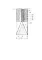
ここで、絞り361を含む測定プローブ3の先端の構成について詳細に説明する。図2は、絞り361を含む測定プローブ3の先端を長手方向に沿って切断した断面を模式的に示す図である。図3は、図1の矢視A方向からの正面図である。 Here, the configuration of the tip of the
図2および図3に示すように、絞り361は、照明ファイバ31が照射する照明領域D1以外を遮蔽する。なお、照明領域D1は、照明ファイバ31の照らす領域よりも内側に設定されても良いが、照明効率、迷光発生の観点から照明ファイバ31の照らす領域と絞り361とが一致していることが望ましい。絞り361は、光を遮蔽する遮蔽部材、たとえば合成樹脂等を用いて形成される。なお、絞り361は、ロッドレンズ36と一体的に形成してもよい。また、絞り361は、照明光のスポットが円であれば円環状が好適である。また、耐久性を増すためや構造的な段差をなくすために、絞りを透明な保護部材で覆っても良い。As shown in FIGS. 2 and 3, the
つぎに、照明ファイバ31および第1検出ファイバ32、第2検出ファイバ33および第3検出ファイバ34それぞれの先端から離間し、照明光および照明光の戻り光が通過可能な面(つまり絞り361が設置される面)における、照明領域と検出領域の関係について説明する。 Next, surfaces that are separated from the tips of the
図2に示すように、第3検出ファイバ34の開口数(NA:Numerical Aperture)で決まる受光可能角度がθ0であっても、絞り361によって第3検出ファイバ34が受光する角度は、θ1に制限されるので、第3検出ファイバ34の検出領域が検出領域D2に制限される。これによって、第3検出ファイバ34の検出領域D2は、照明ファイバ31が照射する照明領域D1に内包される。第1検出ファイバ32、第2検出ファイバ33についても同様に、検出領域は、照明ファイバ31が照射する照明領域D1に内包される。照明領域D1は、照明ファイバ31の照らす領域よりも十分内側に設定される場合に、各検出ファイバの検出領域すべてと照明領域をすべて一致させて設定させることもできる。As shown in FIG. 2, even if the receivable angle determined by the numerical aperture (NA: Numerical Aperture) of the
以上のように構成された生体光学測定システム1は、図4に示すように、内視鏡システム100の内視鏡装置101(内視鏡スコープ)に設けられた処置具チャンネル101aを介して測定プローブ3が被検体内に挿入され、照明ファイバ31が測定対象物S1に照明光を照射し、第1検出ファイバ32、第2検出ファイバ33および第3検出ファイバ34がそれぞれ測定対象物S1で反射および/または散乱した照明光の戻り光を異なる散乱角度で検出して第1検出部23、第2検出部24および第3検出部25に伝播する。その後、演算部291は、第1検出部23、第2検出部24および第3検出部25がそれぞれ検出した検出結果に基づいて、測定対象物S1の性状の特性値を演算する。 The
つぎに、上述した生体光学測定システム1のキャリブレーション処理を含む演算処理の一例について説明する。図5は、キャリブレーション用データ取得の様子を模式的に示す図である。 Next, an example of a calculation process including the calibration process of the above-described biological
図5に示すように、生体光学測定システム1は、測定プローブ3を生体光学測定装置2に接続した際に、キャリブレーション処理として測定プローブ3の先端から一様の強度の照明P1が照射される。この場合、制御部29は、第1検出部23、第2検出部24および第3検出部25がそれぞれ検出した検出結果を記録部28に記録する。 As shown in FIG. 5, when the
続いて、キャリブレーション処理時の第1検出部23の検出結果をC1、第2検出部24の検出結果をC2および第3検出部25の検出結果をC3とし、測定対象物S1の第1検出部23の検出結果をR1、第2検出部24の検出結果をR2および第3検出部25の検出結果をR3、補正後の第1検出部23、第2検出部24および第3検出部25の値をI1〜I3としたとき、演算部291は、以下の式(1)〜(3)によって測定対象物S1の測定値を算出する。
I1=R1(C1+C2+C3)/3C1 ・・・(1)
I2=R2(C1+C2+C3)/3C2 ・・・(2)
I3=R3(C1+C2+C3)/3C3 ・・・(3)
このように、演算部291は、キャリブレーション処理の検出結果と実測定時の検出結果とに基づいて、補正後の第1検出部23、第2検出部24および第3検出部25の値を演算し、この補正後の値に応じて測定対象物S1の測定値を演算する。さらに、図6に示すように、絞り361は、LEBS測定に用いる照明光の戻り光Y1のみをロッドレンズ36内に入射させ、LEBS測定に関係のない拡散光成分Y2をロッドレンズ36内に入射することを防止する。Subsequently, the detection result of the
I1 = R1 (C1 + C2 + C3 ) / 3C1 (1)
I2 = R2 (C1 + C2 + C3 ) / 3C2 (2)
I3 = R3 (C1 + C2 + C3 ) / 3C3 (3)
As described above, the
以上説明した本発明の実施の形態1では、ロッドレンズ36の先端に照明ファイバ31が照射する照明範囲外を覆う絞り361を設けたので、キャリブレーション処理時と測定対象物S1の測定時で検出領域が変化することを防止できるので、正確な検出効率のキャリブレーションに基づく測定を行うことができる。 In the first embodiment of the present invention described above, the
さらに、本発明の実施の形態1では、第1検出ファイバ32、第2検出ファイバ33および第3検出ファイバ34それぞれに対して同じ検出領域でキャリブレーション処理を実行することができるので、正確なキャリブレーション処理を実行することができる。 Furthermore, in the first embodiment of the present invention, since the calibration process can be executed in the same detection region for each of the
つまり、本発明の実施の形態1では、キャリブレーション処理時に第1検出ファイバ32、第2検出ファイバ33および第3検出ファイバ34それぞれに入射する光束の角度と、測定対象物S1の実測時に第1検出ファイバ32、第2検出ファイバ33および第3検出ファイバ34それぞれに入射する光束の角度とを一致させている。この結果、第1検出ファイバ32、第2検出ファイバ33および第3検出ファイバ34、生体光学測定装置2内の中継ファイバまたは第1検出部23、第2検出部24および第3検出部25における角度依存の個体間のばらつきをキャリブレーション処理によって確実に校正することができる。 That is, in the first embodiment of the present invention, the angle of the light beam incident on each of the
(実施の形態1の変形例1)
本発明の実施の形態1では、ロッドレンズの側壁により照明光を遮蔽することによっても実現できる。図7は、本発明の一実施の形態の変形例1にかかる測定プローブを長手方向に沿って切断した断面を模式的に示す図である。なお、上述した実施の形態と同一の構成には同一の符号を付して説明する。(
The first embodiment of the present invention can also be realized by shielding the illumination light with the side wall of the rod lens. FIG. 7 is a diagram schematically showing a cross section of the measurement probe according to the first modification of the embodiment of the present invention cut along the longitudinal direction. In addition, the same code | symbol is attached | subjected and demonstrated to the structure same as embodiment mentioned above.
図7に示す測定プローブ4は、照明ファイバ31と、第1検出ファイバ32と、第2検出ファイバ33と、第3検出ファイバ34と、ファイバ保持部35と、ロッドレンズ40と、を備える。 The measurement probe 4 shown in FIG. 7 includes an
ロッドレンズ40は、ファイバ保持部35の先端に設けられる。具体的には、ロッドレンズ40は、光の透過性のみ持ちレンズのような光路曲げ効果を持たないガラスロッドまたはプラスチックロッド、あるいは曲率を持つ光学レンズまたは屈折率分布型レンズ(GRINレンズ)が用いられる。レンズを用いる場合は、照明ファイバ31、第1検出ファイバ32、第2検出ファイバ33および第3検出ファイバ34それぞれの先端にレンズの焦点面が来るように設置する。ロッドレンズ40は、照明ファイバ31、第1検出ファイバ32、第2検出ファイバ33および第3検出ファイバ34それぞれの先端と測定対象物S1との距離が一定となるように円柱状をなす。また、ロッドレンズ40の外径は、照明ファイバ31が照射する照明領域D1と一致または照明ファイバ31が照射する照明領域D1の内側に相当する大きさに形成される。The
以上説明した本発明の実施の形態1の変形例1によれば、ロッドレンズ40の外径は、照明ファイバ31が照射する照明領域D1と一致もしくは照明ファイバ31が照射する照明領域D1の内側に相当する大きさ有する。この結果、キャリブレーション処理時と測定対象物S1の測定時との検出領域のずれを防止することができるので、精度の高い測定を行うことができる。According to the first modification of the first embodiment of the present invention described above, the outer diameter of the
(実施の形態1の変形例2)
本発明の実施の形態1では、上述の絞りやロッドレンズ外壁によって照明領域を制限した構成において、NAの大きな検出ファイバを用いてもよい。図8は、本発明の一実施の形態の変形例2にかかる測定プローブを長手方向に沿って切断した断面を模式的に示す図である。なお、上述した実施の形態と同一の構成には同一の符号を付して説明する。(
In the first embodiment of the present invention, a detection fiber having a large NA may be used in the configuration in which the illumination area is limited by the above-described stop or rod lens outer wall. FIG. 8 is a diagram schematically showing a cross section of the measurement probe according to the second modification of the embodiment of the present invention cut along the longitudinal direction. In addition, the same code | symbol is attached | subjected and demonstrated to the structure same as embodiment mentioned above.
図8に示す測定プローブ5は、照明ファイバ31と、第1検出ファイバ32と、第2検出ファイバ33と、第3検出ファイバ34と、ファイバ保持部35と、ロッドレンズ36と、絞り361と、を備える。 The
図8に示すように、第1検出ファイバ32、第2検出ファイバ33および第3検出ファイバ34それぞれの開口数(NA)が大きいことにより、照明ファイバ31が照射する照明領域D1より受光可能領域が大きい。これにより、検出ファイバの検出領域D2は照明領域D1と等しくなる。As shown in FIG. 8, the
以上説明した本発明の実施の形態1の変形例2によれば、第1検出ファイバ32、第2検出ファイバ33および第3検出ファイバ34それぞれの開口数が大きいことにより、検出ファイバの検出領域D2は照明領域D1と等しくなる。この結果、キャリブレーション処理時と測定対象物S1の測定時との検出領域のずれを防止することができるので、精度の高い検出効率のキャリブレーションに基づいた測定を行うことができる。さらに、生体組織で反射および/散乱した照明光の戻り光を効率良く検出できる。According to the second modification of the first embodiment of the present invention described above, the detection area D of the detection fiber is increased because the numerical apertures of the
(実施の形態1の変形例3)
本発明の実施の形態1では、ファイバ保持部およびロッドレンズの形状を変更してもよい。図9は、本発明の実施の形態1の変形例3にかかる測定プローブを長手方向に沿って切断した断面図を模式的に示す図である。なお、上述した実施の形態と同一の構成には同一の符号を付して説明する。(
In the first embodiment of the present invention, the shape of the fiber holding portion and the rod lens may be changed. FIG. 9 is a diagram schematically illustrating a cross-sectional view of the measurement probe according to the third modification of the first embodiment of the present invention cut along the longitudinal direction. In addition, the same code | symbol is attached | subjected and demonstrated to the structure same as embodiment mentioned above.
図9に示す測定プローブ6は、照明ファイバ31と、第1検出ファイバ32と、第2検出ファイバ33と、第3検出ファイバ34と、ファイバ保持部61と、ロッドレンズ62と、絞り361と、を備える。 The
ファイバ保持部61は、照明ファイバ31、第1検出ファイバ32、第2検出ファイバ33および第3検出ファイバ34それぞれ先端を任意の配列に並べて保持する。ファイバ保持部35は、照明ファイバ31、第1検出ファイバ32、第2検出ファイバ33および第3検出ファイバ34の光軸が互いに平行になるように保持する。また、ファイバ保持部61は、ガラス、樹脂または金属等を用いて実現される。また、ファイバ保持部61の先端は、第1検出ファイバ32、第2検出ファイバ33および第3検出ファイバ34の出射光軸を斜めにして照明ファイバ31による照明領域D1と第1検出ファイバ32、第2検出ファイバ33および第3検出ファイバ34それぞれの検出領域とが略一致するように先端がロッドレンズ62に向けて球面に形成されている。The
ロッドレンズ62は、ファイバ保持部61の先端に設けられる。ロッドレンズ62は、所定の透過性を有するガラスやプラスチック等を用いて実現される。具体的には、ロッドレンズ36は、光の透過性のみ持ちレンズのような光路曲げ効果を持たないガラスロッドまたはプラスチックロッド、あるいは曲率を持つ光学レンズまたは屈折率分布型レンズ(GRINレンズ)が用いられる。ロッドレンズ36でレンズを用いる場合は、照明ファイバ31の先端にレンズの焦点面が来るように設置する。ロッドレンズ62は、ファイバ保持部61と接続する接続面が球状に形成されている。ここで、ファイバのコア屈折率がロッドレンズ62の屈折率よりも大きい場合に、ファイバ保持部61は、ロッドレンズ62と接触する側の端面が外部に向けて凸となるように球面状をなしている。換言すれば、ファイバ保持部61は、ファイバ保持部61を略円柱としてみたとき、この円柱の中心軸を通過する平面を切断面とする断面において、端面が照明ファイバ31、第1検出ファイバ32、第2検出ファイバ33および第3検出ファイバ34の配列方向に沿って弧状をなす。また、ロッドレンズ62においても、ファイバ保持部61と接触する側の端面が、ファイバ保持部61に応じた凹形状をなしている。ファイバのコア屈折率がロッドレンズ62の屈折率よりも小さい場合は、ファイバ保持部61は、ロッドレンズ62と接触する側の端面が外部に向けて凹となるように球面状をなし、ロッドレンズ62の、ファイバ保持部61と接触する側の端面が、ファイバ保持部61に応じた凸形状をなしている。 The
以上説明した本発明の実施の形態1の変形例3によれば、ファイバ保持部61の先端は、第1検出ファイバ32、第2検出ファイバ33および第3検出ファイバ34の出射光軸を斜めにして照明ファイバ31による照明領域D1と第1検出ファイバ32、第2検出ファイバ33および第3検出ファイバ34それぞれの検出領域とが略一致するように先端がロッドレンズ62に向けて球面をなす。さらに、ロッドレンズ62の先端に絞りまたはロッドレンズ外壁で検出領域を照明領域内に制限することで、キャリブレーション処理時と測定対象物S1の測定時との検出領域のずれを防止し、第1検出ファイバ32、第2検出ファイバ33および第3検出ファイバ34の余計な受光可能範囲をなくすことによりロッドレンズ62内で発生する乱反射による迷光の影響を軽減させることができるので、精度の高い検出効率のキャリブレーションに基づく測定を行うことができる。さらに、生体組織で反射および/散乱した照明光の戻り光を効率良く検出できる。According to the third modification of the first embodiment of the present invention described above, the distal end of the
(実施の形態2)
つぎに、本発明の実施の形態2について説明する。本実施の形態2にかかる光学測定システムは、上述した実施の形態1にかかる生体光学測定システムの測定プローブの構成が異なる。このため、以下においては、本実施の形態2にかかる生体光学測定システムの測定プローブの構成を説明する。なお、上述した実施の形態1にかかる生体光学測定システム1と同様の構成には同一の符号を付して説明を省略する。(Embodiment 2)
Next, a second embodiment of the present invention will be described. The optical measurement system according to the second embodiment is different in the configuration of the measurement probe of the biological optical measurement system according to the first embodiment described above. For this reason, below, the structure of the measurement probe of the bio-optical measurement system concerning this
図10は、本実施の形態2にかかる生体光学測定システムの構成を模式的に示すブロック図である。図11は、本実施の形態2にかかる生体光学測定システムの測定プローブの先端を長手方向に沿って切断した断面を模式的に示す図である。図12は、図10の矢視A方向からの正面図である。 FIG. 10 is a block diagram schematically showing the configuration of the biological optical measurement system according to the second embodiment. FIG. 11 is a diagram schematically showing a cross section of the tip of the measurement probe of the biological optical measurement system according to the second embodiment cut along the longitudinal direction. 12 is a front view from the direction of arrow A in FIG.
図10に示す生体光学測定システム100は、散乱体である生体組織等の測定対象物に対して光学測定を行って測定対象物の性状(特性)を検出する生体光学測定装置2と、生体光学測定装置2に対して着脱自在である測定プローブ103と、を備える。 The
つぎに、測定プローブ103について説明する。なお、以下においては、検出ファイバが3本の場合を例としてあげるが、さらに複数の検出ファイバがある場合も同様である。図10〜図12に示す測定プローブ103は、照明ファイバ131、第1検出ファイバ132(第1受光チャンネル)、第2検出ファイバ133(第2受光チャンネル)および第3検出ファイバ134(第3受光チャンネル)を内部で挿通するとともに、一端で生体光学測定装置2のコネクタ部22に着脱自在に接続し、可撓性を有する管状をなす可撓部135と、可撓部135の他端に接続され、照明ファイバ131、第1検出ファイバ132、第2検出ファイバ133および第3検出ファイバ134を保持するファイバ保持部136と、ファイバ保持部136の先端に設けられるロッドレンズ137(光学素子)と、を備える。照明ファイバ131、第1検出ファイバ132、第2検出ファイバ133および第3検出ファイバ134は、可撓部135がコネクタ部22に接続されると、光源部21、第1検出部23、第2検出部24および第3検出部25とそれぞれ接続する。また、可撓部135の一端には、コネクタ部22と接続する図示しない接続機構が設けられている。 Next, the
照明ファイバ131は、光ファイバを用いて実現され、コネクタ部22を介して光源部21から入射された照明光を、ロッドレンズ137を介して測定対象物S1に照射する。照明ファイバ131は、一本または複数の光学ファイバが束ねられて構成される。 The
第1検出ファイバ132は、光ファイバを用いて実現され、ロッドレンズ137を介して測定対象物S1で反射および/または散乱した照明光の戻り光を検出(受光)して第1検出部23へ伝播する。 The
第2検出ファイバ133は、光ファイバを用いて実現され、ロッドレンズ137を介して測定対象物S1で反射および/または散乱した照明光の戻り光を検出して第2検出部24へ伝播する。 The
第3検出ファイバ134は、光ファイバを用いて実現され、ロッドレンズ137を介して測定対象物S1で反射および/または散乱した照明光の戻り光を検出して第3検出部25へ伝播する。 The
ファイバ保持部136は、照明ファイバ131、第1検出ファイバ132、第2検出ファイバ133および第3検出ファイバ134のそれぞれの先端を任意の配列に並べて保持する。図12においては、照明ファイバ131、第1検出ファイバ132、第2検出ファイバ133および第3検出ファイバ134を一直線上に並べた場合を示す。また、ファイバ保持部136は、照明ファイバ131、第1検出ファイバ132、第2検出ファイバ133および第3検出ファイバ134の光軸が互いに平行になるように保持する。ファイバ保持部136は、ガラス、樹脂または金属等を用いて実現される。 The
ロッドレンズ137は、ファイバ保持部136の先端に設けられる。ロッドレンズ137は、所定の透過性を有するガラスやプラスチック等を用いて実現される。具体的には、ロッドレンズ137は、光の透過性のみ持ちレンズのような光路曲げ効果を持たないガラスロッドまたはプラスチックロッド、あるいは曲率を持つ光学レンズまたは屈折率分布型レンズ(GRINレンズ)が用いられる。ロッドレンズ36でレンズを用いる場合は、照明ファイバ31、第1検出ファイバ32、第2検出ファイバ33および第3検出ファイバ34それぞれの先端にレンズの焦点面が来るように設置する。ロッドレンズ137は、照明ファイバ131、第1検出ファイバ132、第2検出ファイバ133および第3検出ファイバ134のそれぞれの先端と測定対象物S1との距離が一定となるように円柱状をなす。 The
図13は、本実施の形態2にかかる生体光学測定システム100の測定プローブ103による照明領域および検出領域を説明するための図である。なお、図13は、ロッドレンズ137の測定対象物S1との接触側の端面における照明領域および検出領域を示している。 FIG. 13 is a diagram for explaining an illumination area and a detection area by the
図13に示すように、照明ファイバ131の照明領域E131は、照明ファイバ131、第1検出ファイバ132、第2検出ファイバ133および第3検出ファイバ134のそれぞれの先端から離間し、照明光および戻り光が通過可能な面(ロッドレンズ137の測定対象物S1との接触側の端面)において、第1検出ファイバ132、第2検出ファイバ133および第3検出ファイバ134のそれぞれの戻り光の検出領域E132,E133,E134をそれぞれ内包する。具体的には、第1検出ファイバ132、第2検出ファイバ133および第3検出ファイバ134のそれぞれの開口数(NA)は、照明ファイバ131が照射する照明領域E131に包含されるように照明ファイバ131の開口数よりも小さい。また、第1検出ファイバ132、第2検出ファイバ133および第3検出ファイバ134それぞれの照明光の戻り光を検出する検出領域E132〜E134は、照明ファイバ131が照射する照明領域E131内に制限される。As shown in FIG. 13, the illumination region E131 of the illumination fiber131 is separated from the respective tips of the
ここで、上述した照明領域E131と検出領域E132〜E134との関係を満たすため、少なくとも照明ファイバ131の開口数が、第1検出ファイバ132、第2検出ファイバ133および第3検出ファイバ134のそれぞれの開口数より大きい。このとき、照明ファイバ131は、第1検出ファイバ132、第2検出ファイバ133および第3検出ファイバ134を形成する材料と異なる材料を用いて形成される。具体的には、ファイバーのコア素材とクラッド素材で屈折率比の異なる材料や材質により各ファイバを形成する。Here, in order to satisfy the relationship between the illumination area E131 and the detection areas E132 to E134 described above, at least the numerical aperture of the
この際、第1検出ファイバ132、第2検出ファイバ133および第3検出ファイバ134のそれぞれの開口数は、同一であってもよいし、異なっていてもよい。第1検出ファイバ132、第2検出ファイバ133および第3検出ファイバ134は、それぞれの検出領域E132〜E134が、照明領域E131に内包されていれば適用可能である。At this time, the numerical apertures of the
以上のように構成された生体光学測定システム100は、上述した図4に示すように、内視鏡システム100の内視鏡装置101(内視鏡スコープ)に設けられた処置具チャンネル101aを介して測定プローブ103が被検体内に挿入され、照明ファイバ131が測定対象物S1に照明光を照射し、第1検出ファイバ132、第2検出ファイバ133および第3検出ファイバ134がそれぞれ測定対象物S1で反射および/または散乱した照明光の戻り光を異なる散乱角度で検出して第1検出部23、第2検出部24および第3検出部25に伝播する。その後、演算部291は、第1検出部23、第2検出部24および第3検出部25がそれぞれ検出した検出結果に基づいて、測定対象物S1の性状の特性値を演算する。 As shown in FIG. 4 described above, the
以上説明した本実施の形態2によれば、ロッドレンズ137の端面において、照明ファイバ131が照射する照明領域E131が、第1検出ファイバ132、第2検出ファイバ133および第3検出ファイバ134のそれぞれの戻り光の検出領域E132〜E134をそれぞれ内包するようにしたので、キャリブレーション処理時と測定対象物の測定時との検出領域のずれを防止し、正確な検出効率のキャリブレーションに基づく測定を行うことができる。According to the second embodiment described above, the illumination region E131 irradiated by the
(実施の形態3)
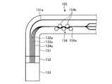
つぎに、本発明の実施の形態3について説明する。図14は、本実施の形態3にかかる光学測定システムの測定プローブを模式的に示す図である。なお、上述したものと同じ構成要素には同じ符号を付してある。上述した実施の形態2では、ファイバの材料や比率を変えて開口数を調整するものとして説明したが、本実施の形態3では、ファイバに応力を加えてファイバー内を大きな角度で伝播する光をファイバー外へ開放することにより、実質の開口数を小さく調整する。(Embodiment 3)
Next, a third embodiment of the present invention will be described. FIG. 14 is a diagram schematically illustrating a measurement probe of the optical measurement system according to the third embodiment. In addition, the same code | symbol is attached | subjected to the same component as what was mentioned above. In the second embodiment described above, the numerical aperture is adjusted by changing the fiber material and ratio. However, in the third embodiment, light that propagates in the fiber at a large angle by applying stress to the fiber is described. By opening to the outside of the fiber, the actual numerical aperture is adjusted to be small.
図14に示す測定プローブ104は、照明ファイバ131a、第1検出ファイバ132a、第2検出ファイバ133aおよび第3検出ファイバ134aを内部で挿通するとともに、一端で生体光学測定装置2のコネクタ部22に着脱自在に接続し、可撓性を有する管状をなす可撓部141と、可撓部141の他端に接続され、照明ファイバ131a、第1検出ファイバ132a、第2検出ファイバ133aおよび第3検出ファイバ134aを保持するファイバ保持部142と、ファイバ保持部142の先端に設けられるロッドレンズ143(光学素子)と、第1検出ファイバ132a、第2検出ファイバ133aおよび第3検出ファイバ134aに対して応力を加えるためのモードフィルター144(応力印加手段)と、を備える。 The
照明ファイバ131a、第1検出ファイバ132a、第2検出ファイバ133aおよび第3検出ファイバ134aは、ファイバーの元の開口数は互いに等しい。 The
ロッドレンズ143は、ファイバ保持部142の先端に設けられる。具体的には、ロッドレンズ143は、光の透過性のみ持ちレンズのような光路曲げ効果を持たないガラスロッドまたはプラスチックロッド、あるいは曲率を持つ光学レンズまたは屈折率分布型レンズ(GRINレンズ)が用いられる。レンズを用いる場合は、照明ファイバ131a、第1検出ファイバ132a、第2検出ファイバ133aおよび第3検出ファイバ134aそれぞれの先端にレンズの焦点面が来るように設置する。ロッドレンズ143は、照明ファイバ131a、第1検出ファイバ132a、第2検出ファイバ133aおよび第3検出ファイバ134aそれぞれの先端と測定対象物との距離が一定となるように円柱状をなす。 The
モードフィルター144は、略円柱状をなし、外周面に第1検出ファイバ132a、第2検出ファイバ133aおよび第3検出ファイバ134aが巻回される。第1検出ファイバ132a、第2検出ファイバ133aおよび第3検出ファイバ134aは、モードフィルター144の外周に沿って巻き付くことで、曲げ応力が加えられた状態となる。ここで、モードフィルター144の長手方向と直交する方向の径(外側面の半径)は、第1検出ファイバ132a、第2検出ファイバ133aおよび第3検出ファイバ134aにおける許容曲げ半径よりも小さい。これにより、モードフィルター144に巻き付いた第1検出ファイバ132a、第2検出ファイバ133aおよび第3検出ファイバ134aは、自身の許容曲げ半径よりも小さい曲率となるように曲げられて応力が加わった状態となっている。 The
第1検出ファイバ132a、第2検出ファイバ133aおよび第3検出ファイバ134aは、応力が加わることによって、ファイバ内部に取り込まれる光の角度範囲が狭くなる。具体的には、ファイバの屈曲部分において、所定の入射角度の光が外部に漏れることによって、検出器に到達する光の角度範囲が狭くなる。これにより、例えば図13に示す検出領域E132〜E134が縮小する。When the
第1検出ファイバ132a、第2検出ファイバ133aおよび第3検出ファイバ134aのモードフィルター144に対する巻き付け態様(巻回数や締め付け強度など)を調節することで、照明ファイバ131aの照明領域(例えば照明領域E131)に各検出領域(例えば検出領域E132〜E134)を内包させることができる。The illumination area (for example, illumination area E131 ) of the
以上説明した本実施の形態3によれば、ロッドレンズ143の端面において、照明ファイバ131aが照射する照明領域が、第1検出ファイバ132a、第2検出ファイバ133aおよび第3検出ファイバ134aのそれぞれの戻り光の各検出領域をそれぞれ内包するようにしたので、キャリブレーション処理時と測定対象物の測定時との検出領域のずれを防止し、正確な検出効率のキャリブレーションに基づく測定を行うことができる。 According to the third embodiment described above, the illumination area irradiated by the
(実施の形態3の変形例)
図15は、本実施の形態3の変形例にかかる光学測定システムの測定プローブを模式的に示す図である。(Modification of Embodiment 3)
FIG. 15 is a diagram schematically illustrating a measurement probe of the optical measurement system according to the modification of the third embodiment.
図15に示す測定プローブ105は、上述した照明ファイバ131a、第1検出ファイバ132a、第2検出ファイバ133aおよび第3検出ファイバ134aを内部で挿通するとともに、一端で生体光学測定装置2のコネクタ部22に着脱自在に接続し、可撓性を有する管状をなす可撓部151と、可撓部151の他端に接続され、照明ファイバ131a、第1検出ファイバ132a、第2検出ファイバ133aおよび第3検出ファイバ134aを保持するファイバ保持部152と、ファイバ保持部152の先端に設けられるロッドレンズ153(光学素子)と、第1検出ファイバ132a、第2検出ファイバ133aおよび第3検出ファイバ134aに対して応力を加えるためのモードフィルター154と、を備える。 The
モードフィルター154は、略円柱状をなす三つの第1柱状部材154aと、略円柱状をなす二つの第2柱状部材154bと、を有する。三つの第1柱状部材154aは、それぞれの中心軸方向が平行となるように配列されてなる。二つの第2柱状部材154bは、それぞれの中心軸方向が平行となるように配列されてなる。また、二つの第2柱状部材154bは、三つの第1柱状部材154aの間に位置するように配設されている。ここで、第1柱状部材154aの半径をR1、第2柱状部材54bの半径をR2、三つの第1柱状部材154aのそれぞれの中心軸を通過する平面と二つの第2柱状部材154bのそれぞれの中心軸を通過する平面との間の距離をDとしたとき、D<R1+R2の関係を満たしている。The
第1検出ファイバ132a、第2検出ファイバ133aおよび第3検出ファイバ134aは、三つの第1柱状部材154aと二つの第2柱状部材154bとの間を通過する。このとき、第1検出ファイバ132a、第2検出ファイバ133aおよび第3検出ファイバ134aは、第1柱状部材154aおよび第2柱状部材154bの側面の一部と接触し、第1柱状部材154aおよび第2柱状部材154bの外周の曲率に合わせて屈曲された状態となる。第1柱状部材154aおよび第2柱状部材154bの外周の曲率を各ファイバの許容曲げ半径よりも小さくすることにより、ファイバ内部に取り込まれる光の角度範囲を狭くすることができる。 The
本実施の形態3の変形例1では、第1柱状部材154aおよび第2柱状部材154bの外周の曲率や、三つの第1柱状部材154aのそれぞれの中心軸を通過する平面と二つの第2柱状部材154bのそれぞれの中心軸を通過する平面との間の距離(D)を調整することにより、第1検出ファイバ132a、第2検出ファイバ133aおよび第3検出ファイバ134aの各検出領域の大きさを調整することが可能となる。 In the first modification of the third embodiment, the curvature of the outer periphery of the
なお、第1柱状部材154aおよび第2柱状部材154bに限らず、櫛状をなす二つの部材によって、第1検出ファイバ132a、第2検出ファイバ133aおよび第3検出ファイバ134aを挟み込んで応力を加えるものであっても適用可能である。 In addition, the
(実施の形態4)
つぎに、本発明の実施の形態4について説明する。図16は、本実施の形態4にかかる光学測定システムの測定プローブを模式的に示す図である。なお、上述したものと同じ構成要素には同じ符号を付してある。上述した実施の形態2では、ファイバの材料や比率を変えて開口数を調整するものとして説明したが、本実施の形態4では、ファイバの端面を傾斜させて照射領域および検出領域を調整する。(Embodiment 4)
Next, a fourth embodiment of the present invention will be described. FIG. 16 is a diagram schematically illustrating a measurement probe of the optical measurement system according to the fourth embodiment. In addition, the same code | symbol is attached | subjected to the same component as what was mentioned above. In the second embodiment described above, the numerical aperture is adjusted by changing the fiber material and ratio, but in the fourth embodiment, the irradiation area and the detection area are adjusted by inclining the end face of the fiber.
図16に示す測定プローブ106の先端は、照明ファイバ131b、第1検出ファイバ132b、第2検出ファイバ133bおよび第3検出ファイバ134bを内部で挿通するとともに、一端で生体光学測定装置2のコネクタ部22に着脱自在に接続し、可撓性を有する管状をなす可撓部161と、可撓部161の他端に接続され、照明ファイバ131b、第1検出ファイバ132b、第2検出ファイバ133bおよび第3検出ファイバ134bを保持するファイバ保持部162と、ファイバ保持部162の先端に設けられるロッドレンズ163(光学素子)と、を備える。 The distal end of the
照明ファイバ131b、第1検出ファイバ132b、第2検出ファイバ133bおよび第3検出ファイバ134bは、開口数(NA)が互いに等しい。 The
ロッドレンズ163は、ファイバ保持部142の先端に設けられる。ロッドレンズ163は、所定の透過性を有するガラスやプラスチック等を用いて実現される。具体的には、ロッドレンズ163は、光の透過性のみ持ちレンズのような光路曲げ効果を持たないガラスロッドまたはプラスチックロッド、あるいは曲率を持つ光学レンズまたは屈折率分布型レンズ(GRINレンズ)が用いられる。ロッドレンズ163でレンズを用いる場合は、照明ファイバ131bの先端にレンズの焦点面が来るように設置する。ロッドレンズ163は、照明ファイバ131b、第1検出ファイバ132b、第2検出ファイバ133bおよび第3検出ファイバ134bのそれぞれの先端と測定対象物S1との距離が一定となるように略円柱状をなす。 The
ここで、ファイバのコア屈折率がロッドレンズ163の屈折率よりも大きい場合に、ファイバ保持部162は、ロッドレンズ163と接触する側の端面が外部に向けて凸となるように球面状をなしている。換言すれば、ファイバ保持部162は、ファイバ保持部162を略円柱としてみたとき、この円柱の中心軸を通過する平面を切断面とする断面において、端面が照明ファイバ131b、第1検出ファイバ132b、第2検出ファイバ133bおよび第3検出ファイバ134bの配列方向に沿って弧状をなす。また、ロッドレンズ163においても、ファイバ保持部162と接触する側の端面が、ファイバ保持部162に応じた凹形状をなしている。ファイバーのコア屈折率がロッドレンズ163の屈折率よりも小さい場合は、ファイバ保持部162は、ロッドレンズ163と接触する側の端面が外部に向けて凹となるように球面状をなし、ロッドレンズ163の、ファイバ保持部162と接触する側の端面が、ファイバ保持部162に応じた凸形状をなしている。 Here, when the core refractive index of the fiber is larger than the refractive index of the
このとき、ファイバ保持部162の端面の球面状の頭頂部に照明ファイバ131bが位置している。すなわち、照明ファイバ131bの配設位置において、ファイバ保持部162の断面における端面の接線方向は、ファイバ保持部162によって直線状に保持された照明ファイバ131bの中心軸と直交している。 At this time, the
ファイバ保持部162の端面が球面状をなすことによって、第1検出ファイバ132b、第2検出ファイバ133bおよび第3検出ファイバ134bの出射光軸を斜めにして、照明ファイバ131b、第1検出ファイバ132b、第2検出ファイバ133bおよび第3検出ファイバ134bの各検出領域を一致させることができる。 By making the end surface of the
以上説明した本実施の形態4によれば、第1検出ファイバ132b、第2検出ファイバ133bおよび第3検出ファイバ134bの出射光軸を斜めにすることによって、照明ファイバ131bが照射する照明領域が、第1検出ファイバ132b、第2検出ファイバ133bおよび第3検出ファイバ134bのそれぞれの戻り光の各検出領域をそれぞれ内包するようにしたので、キャリブレーション処理時と測定対象物の測定時との検出領域のずれを防止し、正確な測定を行うことができる。 According to the fourth embodiment described above, the illumination area irradiated by the
1,100 生体光学測定システム
2 生体光学測定装置
3,4,5,6,103,104,105,106 測定プローブ
20 電源
21 光源部
22 コネクタ部
23 第1検出部
24 第2検出部
25 第3検出部
26 入力部
27 出力部
28 記録部
29 制御部
31,131,131a,131b 照明ファイバ
32,132,132a,132b 第1検出ファイバ
33,133,133a,133b 第2検出ファイバ
34,134,134a,134b 第3検出ファイバ
35,61,136,142,152,162 ファイバ保持部
36,40,62,137,143,153,163 ロッドレンズ
144,154 モードフィルター
135,141,151,161 可撓部
291 演算部DESCRIPTION OF SYMBOLS 1,100
Claims (10)
Translated fromJapanese前記生体組織に対して照明光を照射する照明ファイバと、
前記生体組織で反射および/または散乱した照明光の戻り光を検出する複数の検出ファイバであって、前記照明ファイバと同一平面上に前記照明ファイバからの距離を異ならせて配置した複数の検出ファイバと、
を備え、
前記照明ファイバおよび前記複数の検出ファイバそれぞれの先端から離間し、前記照明光および前記戻り光が通過可能な面において、前記複数の検出ファイバそれぞれの前記戻り光の検出領域が前記照明ファイバの照明領域と一致することを特徴とする測定プローブ。A measurement probe that is detachably connected to a biological optical measurement device that performs optical measurement of biological tissue,
An illumination fiber for illuminating the living tissue with illumination light;
Aplurality of detection fibers for detecting return light of the illumination light reflected and / or scattered by the biological tissue, wherein theplurality of detection fibers are arranged at different distances from the illumination fiber on the same plane as the illumination fiber. When,
With
The detection region of the return light of each of the plurality of detection fibers is an illumination region of the illumination fiber on a surface that is spaced from the distal ends of the illumination fiber and the plurality of detection fibers and through which the illumination light and the return light can pass. A measuring probe characterizedby matching .
前記光学素子の先端に設けられ、前記照明領域全てまたは前記照明領域の内側の領域のみを透過させ、それ以外の領域を遮蔽する絞りと、
を備えたことを特徴とする請求項1に記載の測定プローブ。An optical element having a cylindrical shape, and making the distance between the tip of each of the illumination fiber and the plurality of detection fibers and the living tissue constant,
A stop provided at the tip of the optical element, transmits all of the illumination area or only the area inside the illumination area, and shields the other areas;
The measurement probe according to claim 1, further comprising:
前記光学素子は、該光学素子の外径が前記照明領域の外径と一致または前記照明領域の内側に設置されることを特徴とする請求項1に記載の測定プローブ。An optical element having a cylindrical shape, further comprising a distance between the tip of each of the illumination fiber and the plurality of detection fibers and the living tissue;
The measurement probe according to claim 1, wherein the optical element has an outer diameter equal to or equal to an outer diameter of the illumination area.
前記測定プローブが着脱自在に接続され、前記測定プローブに照明光を供給するとともに、前記測定プローブから出射された前記戻り光を受光して前記生体組織の光学測定を行う光学測定装置と、
を備えたことを特徴とする生体光学測定システム。A measurement probe according to any one of claims 1 to9 ,
An optical measurement device that is detachably connected to the measurement probe, supplies illumination light to the measurement probe, receives the return light emitted from the measurement probe, and performs optical measurement of the biological tissue;
A bio-optical measurement system comprising:
Applications Claiming Priority (5)
| Application Number | Priority Date | Filing Date | Title |
|---|---|---|---|
| US201261700651P | 2012-09-13 | 2012-09-13 | |
| US61/700,651 | 2012-09-13 | ||
| US201361777363P | 2013-03-12 | 2013-03-12 | |
| US61/777,363 | 2013-03-12 | ||
| PCT/JP2013/074400WO2014042156A1 (en) | 2012-09-13 | 2013-09-10 | Measurement probe and biological optical measurement system |
Publications (2)
| Publication Number | Publication Date |
|---|---|
| JPWO2014042156A1 JPWO2014042156A1 (en) | 2016-08-18 |
| JP6173325B2true JP6173325B2 (en) | 2017-08-02 |
Family
ID=50278267
Family Applications (1)
| Application Number | Title | Priority Date | Filing Date |
|---|---|---|---|
| JP2014535554AExpired - Fee RelatedJP6173325B2 (en) | 2012-09-13 | 2013-09-10 | Measuring probe and bio-optical measurement system |
Country Status (5)
| Country | Link |
|---|---|
| US (1) | US10149619B2 (en) |
| EP (1) | EP2896350A4 (en) |
| JP (1) | JP6173325B2 (en) |
| CN (1) | CN104619235B (en) |
| WO (1) | WO2014042156A1 (en) |
Families Citing this family (12)
| Publication number | Priority date | Publication date | Assignee | Title |
|---|---|---|---|---|
| US9417418B2 (en) | 2011-09-12 | 2016-08-16 | Commscope Technologies Llc | Flexible lensed optical interconnect device for signal distribution |
| NZ706687A (en) | 2012-09-28 | 2017-09-29 | Adc Telecommunications Inc | Fiber optic cassette |
| US9223094B2 (en) | 2012-10-05 | 2015-12-29 | Tyco Electronics Nederland Bv | Flexible optical circuit, cassettes, and methods |
| CN106998999B (en)* | 2014-12-12 | 2018-07-13 | 奥林巴斯株式会社 | Measuring probe and optical measurement instrument for living system |
| JP6629118B2 (en)* | 2016-03-30 | 2020-01-15 | 三菱重工業株式会社 | Optical sensor and rotating machine |
| WO2018046677A1 (en) | 2016-09-08 | 2018-03-15 | CommScope Connectivity Belgium BVBA | Telecommunications distribution elements |
| JP7076954B2 (en)* | 2017-06-13 | 2022-05-30 | 株式会社キーエンス | Confocal displacement meter |
| JP6971645B2 (en)* | 2017-06-13 | 2021-11-24 | 株式会社キーエンス | Confocal displacement meter |
| WO2019030833A1 (en)* | 2017-08-08 | 2019-02-14 | オリンパス株式会社 | Vibration spectrum measuring device |
| US11409068B2 (en) | 2017-10-02 | 2022-08-09 | Commscope Technologies Llc | Fiber optic circuit and preparation method |
| WO2019186718A1 (en)* | 2018-03-27 | 2019-10-03 | 株式会社住田光学ガラス | Optical fiber bundle, endoscope scope, and endoscope |
| US12339511B2 (en) | 2020-03-31 | 2025-06-24 | Commscope Technologies Llc | Fiber optic cable management systems and methods |
Family Cites Families (31)
| Publication number | Priority date | Publication date | Assignee | Title |
|---|---|---|---|---|
| JPS5429182Y2 (en)* | 1975-10-11 | 1979-09-18 | ||
| JPS57185833A (en)* | 1981-05-13 | 1982-11-16 | Olympus Optical Co | Endoscope apparatus |
| US4830460A (en)* | 1987-05-19 | 1989-05-16 | Advanced Interventional Systems, Inc. | Guidance system and method for delivery system for high-energy pulsed ultraviolet laser light |
| US20020045811A1 (en)* | 1985-03-22 | 2002-04-18 | Carter Kittrell | Laser ablation process and apparatus |
| US5192278A (en)* | 1985-03-22 | 1993-03-09 | Massachusetts Institute Of Technology | Multi-fiber plug for a laser catheter |
| US5199431A (en)* | 1985-03-22 | 1993-04-06 | Massachusetts Institute Of Technology | Optical needle for spectroscopic diagnosis |
| US5693043A (en)* | 1985-03-22 | 1997-12-02 | Massachusetts Institute Of Technology | Catheter for laser angiosurgery |
| US4669467A (en)* | 1985-03-22 | 1987-06-02 | Massachusetts Institute Of Technology | Mode mixer for a laser catheter |
| US6174424B1 (en)* | 1995-11-20 | 2001-01-16 | Cirrex Corp. | Couplers for optical fibers |
| US6373573B1 (en)* | 2000-03-13 | 2002-04-16 | Lj Laboratories L.L.C. | Apparatus for measuring optical characteristics of a substrate and pigments applied thereto |
| CN1341209A (en)* | 1999-01-25 | 2002-03-20 | 牛顿实验室公司 | Imaging of tissue using polarized light |
| US6615072B1 (en)* | 1999-02-04 | 2003-09-02 | Olympus Optical Co., Ltd. | Optical imaging device |
| US7299080B2 (en)* | 1999-10-08 | 2007-11-20 | Sensys Medical, Inc. | Compact apparatus for noninvasive measurement of glucose through near-infrared spectroscopy |
| EP1244927B1 (en)* | 1999-12-17 | 2005-09-07 | Digital Optical Imaging Corporation | Methods and apparatus for imaging using a light guide bundle and a spatial light modulator |
| JP2002065581A (en)* | 2000-08-25 | 2002-03-05 | Fuji Photo Film Co Ltd | Endoscope device |
| EP1441215B1 (en)* | 2001-10-31 | 2012-08-01 | Olympus Corporation | Optical scanning type observation device |
| EP1472517A1 (en)* | 2002-01-18 | 2004-11-03 | Newton Laboratories, Inc. | Spectroscopic diagnostic methods and system |
| US20040073120A1 (en)* | 2002-04-05 | 2004-04-15 | Massachusetts Institute Of Technology | Systems and methods for spectroscopy of biological tissue |
| JP4535697B2 (en)* | 2003-07-23 | 2010-09-01 | オリンパス株式会社 | Endoscope device for light scattering observation of biological tissue |
| US7331954B2 (en)* | 2004-04-08 | 2008-02-19 | Omniguide, Inc. | Photonic crystal fibers and medical systems including photonic crystal fibers |
| JP2006192027A (en)* | 2005-01-12 | 2006-07-27 | Olympus Corp | Endoscope apparatus |
| US9314164B2 (en) | 2005-10-27 | 2016-04-19 | Northwestern University | Method of using the detection of early increase in microvascular blood content to distinguish between adenomatous and hyperplastic polyps |
| US20070239232A1 (en)* | 2006-03-28 | 2007-10-11 | Eastman Kodak Company | Light guide based light therapy device |
| JP2009537014A (en)* | 2006-05-12 | 2009-10-22 | ノースウェスタン ユニバーシティ | Low coherence enhanced backscatter spectroscopy system, method and apparatus |
| US8131348B2 (en)* | 2006-05-12 | 2012-03-06 | Northshore University Healthsystem | Systems, methods and apparatuses of elastic light scattering spectroscopy and low coherence enhanced backscattering spectroscopy |
| WO2007136880A2 (en)* | 2006-05-19 | 2007-11-29 | Northshore University Health System | Method & apparatus for recognizing abnormal tissue using the detection of early increase in microvascular blood content |
| US20140324138A1 (en)* | 2007-05-09 | 2014-10-30 | Massachusetts Institute Of Technology | Wirelessly-powered illumination of biological tissue |
| JP5449816B2 (en)* | 2009-03-26 | 2014-03-19 | オリンパス株式会社 | Image processing apparatus, image processing program, and method of operating image processing apparatus |
| WO2012057151A1 (en)* | 2010-10-29 | 2012-05-03 | オリンパス株式会社 | Optical measurement device and probe device |
| EP2620093A1 (en)* | 2010-10-29 | 2013-07-31 | Olympus Corporation | Optical measurement device and probe |
| WO2013133339A1 (en)* | 2012-03-07 | 2013-09-12 | オリンパス株式会社 | Measurement probe |
- 2013
- 2013-09-10EPEP13837690.0Apatent/EP2896350A4/ennot_activeWithdrawn
- 2013-09-10WOPCT/JP2013/074400patent/WO2014042156A1/enactiveApplication Filing
- 2013-09-10JPJP2014535554Apatent/JP6173325B2/ennot_activeExpired - Fee Related
- 2013-09-10CNCN201380047647.3Apatent/CN104619235B/ennot_activeExpired - Fee Related
- 2015
- 2015-02-23USUS14/628,652patent/US10149619B2/enactiveActive
Also Published As
| Publication number | Publication date |
|---|---|
| JPWO2014042156A1 (en) | 2016-08-18 |
| EP2896350A4 (en) | 2016-06-15 |
| WO2014042156A1 (en) | 2014-03-20 |
| EP2896350A1 (en) | 2015-07-22 |
| CN104619235A (en) | 2015-05-13 |
| CN104619235B (en) | 2017-03-29 |
| US10149619B2 (en) | 2018-12-11 |
| US20150164333A1 (en) | 2015-06-18 |
Similar Documents
| Publication | Publication Date | Title |
|---|---|---|
| JP6173325B2 (en) | Measuring probe and bio-optical measurement system | |
| JP6205346B2 (en) | Optical measuring apparatus and fiber bundle association method | |
| US9329124B2 (en) | Scattered light measurement apparatus | |
| EP2653854B1 (en) | Optical measuring system and calibration method | |
| JP5485480B1 (en) | Fiber unit | |
| JP2016073687A (en) | Optical measurement device and probe | |
| JP6237648B2 (en) | Probe, spectroscopic measurement device, and diagnostic system | |
| JP5988983B2 (en) | Calibration apparatus and calibration method | |
| JP5404933B2 (en) | Measuring endoscope | |
| JP6492107B2 (en) | Measuring probe and bio-optical measurement system | |
| JP6028015B2 (en) | Measuring probe | |
| JP5596870B2 (en) | Measuring probe | |
| JP5439631B1 (en) | Bio-optical measurement device and measurement probe | |
| WO2015174543A1 (en) | Measurement probe and optical measurement system | |
| US20110201942A1 (en) | Device and method for optically examining the interior of a body part | |
| WO2013140690A1 (en) | Measurement probe and bio-optical measurement system | |
| US20150201842A1 (en) | Measurement probe and optical measurement system |
Legal Events
| Date | Code | Title | Description |
|---|---|---|---|
| A131 | Notification of reasons for refusal | Free format text:JAPANESE INTERMEDIATE CODE: A131 Effective date:20170221 | |
| A521 | Request for written amendment filed | Free format text:JAPANESE INTERMEDIATE CODE: A523 Effective date:20170411 | |
| TRDD | Decision of grant or rejection written | ||
| A01 | Written decision to grant a patent or to grant a registration (utility model) | Free format text:JAPANESE INTERMEDIATE CODE: A01 Effective date:20170627 | |
| A61 | First payment of annual fees (during grant procedure) | Free format text:JAPANESE INTERMEDIATE CODE: A61 Effective date:20170704 | |
| R151 | Written notification of patent or utility model registration | Ref document number:6173325 Country of ref document:JP Free format text:JAPANESE INTERMEDIATE CODE: R151 | |
| R250 | Receipt of annual fees | Free format text:JAPANESE INTERMEDIATE CODE: R250 | |
| LAPS | Cancellation because of no payment of annual fees |