JP6171909B2 - Chromaticity correction device - Google Patents
Chromaticity correction deviceDownload PDFInfo
- Publication number
- JP6171909B2 JP6171909B2JP2013257241AJP2013257241AJP6171909B2JP 6171909 B2JP6171909 B2JP 6171909B2JP 2013257241 AJP2013257241 AJP 2013257241AJP 2013257241 AJP2013257241 AJP 2013257241AJP 6171909 B2JP6171909 B2JP 6171909B2
- Authority
- JP
- Japan
- Prior art keywords
- chromaticity
- light source
- distance
- correction
- target
- Prior art date
- Legal status (The legal status is an assumption and is not a legal conclusion. Google has not performed a legal analysis and makes no representation as to the accuracy of the status listed.)
- Expired - Fee Related
Links
- 238000012937correctionMethods0.000titleclaimsdescription362
- 238000001514detection methodMethods0.000claimsdescription51
- 239000003086colorantSubstances0.000claimsdescription21
- 238000013459approachMethods0.000claimsdescription10
- 239000000203mixtureSubstances0.000claims1
- 238000010586diagramMethods0.000description29
- 238000000034methodMethods0.000description19
- 238000013500data storageMethods0.000description8
- 239000000446fuelSubstances0.000description6
- 230000002159abnormal effectEffects0.000description5
- 238000005286illuminationMethods0.000description5
- 238000012545processingMethods0.000description3
- XLYOFNOQVPJJNP-UHFFFAOYSA-NwaterSubstancesOXLYOFNOQVPJJNP-UHFFFAOYSA-N0.000description3
- 230000006870functionEffects0.000description2
- 238000004519manufacturing processMethods0.000description2
- 238000005259measurementMethods0.000description2
- 235000005811Viola aduncaNutrition0.000description1
- 240000009038Viola odorataSpecies0.000description1
- 235000013487Viola odorataNutrition0.000description1
- 235000002254Viola papilionaceaNutrition0.000description1
- 230000005856abnormalityEffects0.000description1
- 239000002826coolantSubstances0.000description1
- 238000013480data collectionMethods0.000description1
- 230000003247decreasing effectEffects0.000description1
- 238000013461designMethods0.000description1
- 230000000694effectsEffects0.000description1
- 239000002828fuel tankSubstances0.000description1
- 239000004973liquid crystal related substanceSubstances0.000description1
- 230000003595spectral effectEffects0.000description1
- 239000010409thin filmSubstances0.000description1
Images


Landscapes
- Liquid Crystal (AREA)
- Liquid Crystal Display Device Control (AREA)
- Control Of Indicators Other Than Cathode Ray Tubes (AREA)
- Controls And Circuits For Display Device (AREA)
- Led Devices (AREA)
Description
Translated fromJapanese本発明は、例えば、表示装置等に使用される光源の色度を補正するための色度補正装置に関するものである。 The present invention relates to a chromaticity correction device for correcting the chromaticity of a light source used in, for example, a display device.
従来の色度補正装置として、例えば、特許文献1に記載されたものが知られている。特許文献1の色度補正装置(LED光源装置)は、例えば、白色点灯する照明装置に適用されており、複数色(赤、緑、青)のLEDが複数組設けられた発光部と、色度補正データを格納する色度補正データ格納部と、発光部の発光状態を制御する点灯部とを備えている。 As a conventional chromaticity correction device, for example, the one described in
発光部に使用される複数のLEDは、光度ランク(光度のばらつき)が、所定ランク(光度ランクF)となるものが予め選別されて採用されている。色度補正データは、別装置である色度補正データ生成装置によって、事前に製造工程にて測定、生成された設定データであり、予め色度補正データ格納部に格納されるようになっている。色度補正データは、上記のように予め選別された複数のLEDにおいて、実際に得られる色度に対して目標とする色度を得るために必要とされる各LEDの色度の割合を決定したものとなっている。 As the plurality of LEDs used in the light emitting unit, those having a luminous intensity rank (variation in luminous intensity) of a predetermined rank (luminous intensity rank F) are selected and adopted in advance. The chromaticity correction data is setting data measured and generated in advance in a manufacturing process by a chromaticity correction data generation device which is a separate device, and is stored in advance in the chromaticity correction data storage unit. . The chromaticity correction data determines the ratio of the chromaticity of each LED required to obtain the target chromaticity with respect to the actually obtained chromaticity in the plurality of LEDs selected in advance as described above. It has become.
点灯部は、色度補正データ格納部から出力される色度補正データに、予め定められた複数のLEDの階調データ(例えば8ビットデータ=256)を乗算して、補正階調データを算出して、この補正階調データに基づいて発光部を点灯させるようにしている。 The lighting unit multiplies the chromaticity correction data output from the chromaticity correction data storage unit by a predetermined plurality of LED gradation data (for example, 8-bit data = 256) to calculate corrected gradation data. Thus, the light emitting unit is turned on based on the corrected gradation data.
しかしながら、上記特許文献1の色度補正装置は、各LEDの光度ランクを予め所定ランクとなるように選別しているので、製造工数の増加を招いてしまう。また、選別された各LEDを用いた場合の色度補正データを事前に把握して、色度補正データ格納部に格納しており、事前のデータ収集工数、および専用の格納部の設定が必要となっている。 However, since the chromaticity correction apparatus of the above-mentioned
本発明の目的は、上記問題に鑑み、光源の事前選別を不要とし、且つ、より簡素な構成で色度の補正を可能とする色度補正装置を提供することにある。 In view of the above problems, an object of the present invention is to provide a chromaticity correction apparatus that eliminates the need for pre-selection of light sources and enables chromaticity correction with a simpler configuration.
本発明は上記目的を達成するために、以下の技術的手段を採用する。 In order to achieve the above object, the present invention employs the following technical means.
第1の発明では、第1の色を発光する第1光源(21)、および第2の色を発光する第2光源(22)を有する光源部(20)において、第1、第2光源(21、22)が同時に点灯されたときの混色の色度(Pm)を、予め定めた所定の光度比となるように設定した目標色の色度(Ps)に近づけるように補正する色度補正装置であって、
第1、第2光源(21、22)の少なくとも一方が点灯されたときの色度座標空間上の色度(P1、P2)を検出する色度検出部(110)と、
色度検出部(110)によって得られた色度(P1、P2)に基づいて、第1、第2光源(21、22)に供給する駆動電流を調整する制御部(120)とを備え、
制御部(120)は、
色度検出部(110)によって検出された第1光源(21)単体の第1色度(P1)、第2光源(22)単体の第2色度(P2)、および混色の色度(Pm)を取得し、
第1色度(P1)、混色の色度(Pm)、および第2色度(P2)を通る直線(L1)上において、目標色の色度(Ps)の位置から、直線(L1)上で最も近い位置を、線上の目標色度(Pc)として算出し、
色度座標空間上の任意の2つの色度間の距離を色度距離と定義したときに、
第1色度(P1)から混色の色度(Pm)までの第1色度距離(ma)と、第2色度(P2)から混色の色度(Pm)までの第2色度距離(na)との比(na/ma)が、
第1色度(P1)から線上の目標色度(Pc)までの第1目標色度距離(m)と、第2色度(P2)から線上の目標色度(Pc)までの第2目標色度距離(n)との比(n/m)となるように、
第1色度距離(ma)と第2色度距離(na)のうち、短い方の色度距離(ma)を調整するための補正係数(n/m×ma/na)を算出して、短い方の色度距離(ma)に対応する光源(21)への駆動電流を補正係数(n/m×ma/na)に基づいて変更して、光度を下げることで、混色の色度(Pm)を目標色の色度(Ps)に近づけるように補正することを特徴としている。In the first invention, in the light source section (20) having the first light source (21) that emits the first color and the second light source (22) that emits the second color, the first and second light sources ( Chromaticity correction that corrects the chromaticity (Pm) of the mixed colors when 21 and 22) are simultaneously turned on so as to be close to the chromaticity (Ps) of the target color set so as to have a predetermined luminous intensity ratio A device,
A chromaticity detector (110) for detecting chromaticity (P1, P2) in the chromaticity coordinate space when at least one of the first and second light sources (21, 22) is turned on;
A control unit (120) for adjusting the drive current supplied to the first and second light sources (21, 22) based on the chromaticity (P1, P2) obtained by the chromaticity detection unit (110),
The control unit (120)
The first chromaticity (P1) of the first light source (21) alone, the second chromaticity (P2) of the second light source (22) alone, and the chromaticity of the mixed colors (Pm) detected by the chromaticity detector (110) )
On the straight line (L1) from the position of the chromaticity (Ps) of the target color on the straight line (L1) passing through the first chromaticity (P1), the mixed chromaticity (Pm), and the second chromaticity (P2). And calculate the closest position on the line as the target chromaticity (Pc),
When the distance between any two chromaticities in the chromaticity coordinate space is defined as the chromaticity distance,
The first chromaticity distance (ma) from the first chromaticity (P1) to the mixed color chromaticity (Pm), and the second chromaticity distance (ma) from the second chromaticity (P2) to the mixed color chromaticity (Pm) ( na)) (na / ma)
The first target chromaticity distance (m) from the first chromaticity (P1) to the target chromaticity (Pc) on the line, and the second target from the second chromaticity (P2) to the target chromaticity (Pc) on the line The ratio (n / m) to the chromaticity distance (n)
Of the first chromaticity distance (ma) and the second chromaticity distance (na), a correction coefficient (n / m × ma / na) for adjusting theshorter chromaticity distance (ma) is calculated,By changing the drive current to the light source (21) corresponding to theshorter chromaticity distance (ma) based on the correction coefficient (n / m × ma / na)and reducing theluminous intensity, the chromaticityof the mixed color ( Pm) is corrected so as to be close to the chromaticity (Ps) of the target color.
この発明によれば、検出した第1色度(p1)、第2色度(P2)、および混色の色度(Pm)を基に各色度距離(m、n、ma、na)を算出し、更に、各色度距離(m、n、ma、na)を基に、駆動電流に対する補正係数(n/m×ma/na)を算出することで、色度補正を行うことができる。つまり、従来技術のように、各光源(21、22)の光度ランクを予め所定ランクに選別しておく必要がない。また、従来技術のように、選別された各光源を用いた場合の色度補正データを事前に把握して、色度補正データ格納部に格納しておく必要もなく、よって、専用の格納部の設定も不要とすることができる。 According to this invention, each chromaticity distance (m, n, ma, na) is calculated based on the detected first chromaticity (p1), second chromaticity (P2), and mixed color chromaticity (Pm). Furthermore, chromaticity correction can be performed by calculating a correction coefficient (n / m × ma / na) for the drive current based on each chromaticity distance (m, n, ma, na). That is, unlike the prior art, it is not necessary to preliminarily sort the light intensity ranks of the light sources (21, 22) into predetermined ranks. Further, unlike the prior art, it is not necessary to grasp in advance the chromaticity correction data when each selected light source is used and store it in the chromaticity correction data storage unit. It is also possible to eliminate the need for setting.
また、第2の発明では、第1の色を発光する第1光源(201)、第2の色を発光する第2光源(202)、および第3の色を発光する第3光源(203)を有する光源部(20)において、第1〜第3光源(201、202、203)が同時に点灯されたときの混色の色度(Pm2)を、予め定めた所定の光度比となるように設定した目標色の色度(Pw)に近づけるように補正する色度補正装置であって、
第1光源(201)、第2光源(202)、および第3光源(203)の少なくとも1つが点灯されたときの色度座標空間上の色度を検出する色度検出部(110)と、
色度検出部(110)によって得られた色度(P1、P2、P3)に基づいて、第1〜第3光源(201、202、203)に供給する駆動電流を調整する制御部(120)とを備え、
制御部(120)は、
色度検出部(110)によって検出された第1光源(201)単体の第1色度(P1)、第2光源(202)単体の第2色度(P2)、および第3光源(203)単体の第3色度(P3)を取得し、
第1色度(P1)および第2色度(P2)を通る第1直線(L1)と、第3色度(P3)および目標色の色度(Pw)を通る第2直線(L2)との交点を第1線上の目標色度(Pv)として算出し、
色度座標空間上の任意の2つの色度間の距離を色度距離と定義したときに、
第1光源(201)と第2光源(202)とを点灯させたときに、色度検出部(110)によって検出される第1直線(L1)上の第1混色の色度(Pm1)に基づいて、第1色度(P1)から第1混色の色度(Pm1)までの第1色度距離(m1a)と、第2色度(P2)から第1混色の色度(Pm1)までの第2色度距離(n1a)との比(n1a/m1a)が、
第1色度(P1)から第1直線上の目標色度(Pv)までの第1目標色度距離(m1)と、第2色度(P2)から第1直線上の目標色度(Pv)までの第2目標色度距離(n1)との比(n1/m1)となるように、
第1色度距離(m1a)と第2色度距離(n1a)のうち、短い方の色度距離1(m1a)を調整するための第1補正係数(n1/m1×m1a/n1a)を算出して、短い方の色度距離1(m1a)に対応する光源(201)への駆動電流を第1補正係数(n1/m1×m1a/n1a)に基づいて変更して、光度を下げる第1ステップと、
第3光源(203)と、駆動電流を変更した状態における第1光源(201)および第2光源(202)とを点灯させたときに、色度検出部(110)によって検出される第2直線(L2)上の第2混色の色度(Pm2)に基づいて、第3色度(P3)から第2混色の色度(Pm2)までの第3色度距離(m2a)と、第1直線上の目標色度(Pv)から第2混色の色度(Pm2)までの第4色度距離(n2a)との比(n2a/m2a)が、
第3色度(P3)から目標色の色度(Pw)までの第3目標色度距離(m2)と、第1線上の目標色度(Pv)から目標色の色度(Pw)までの第4目標色度距離(n2)との比(n2/m2)となるように、
第3色度距離(m2a)と第4色度距離(n2a)のうち、短い方の色度距離2(m2a)を調整するための第2補正係数(n2/m2×m2a/n2a)を算出して、短い方の色度距離2(m2a)に対応する光源(P3)への駆動電流を第2補正係数(n2/m2×m2a/n2a)に基づいて変更して、光度を下げる第2ステップとを実行して、
第1混色の色度(Pm1)を第1線上の目標色度(Pv)に近づけるように補正すると共に、第2混色の色度(Pm2)を目標色の色度(Pw)に近づけるように補正することを特徴としている。In the second invention, the first light source (201) that emits the first color, the second light source (202) that emits the second color, and the third light source (203) that emits the third color. In the light source unit (20) having the above, the mixed color chromaticity (Pm2) when the first to third light sources (201, 202, 203) are simultaneously turned on is set to have a predetermined light intensity ratio. A chromaticity correction device that corrects the chromaticity (Pw) of the target color to be close to the target color,
A chromaticity detection unit (110) that detects chromaticity in a chromaticity coordinate space when at least one of the first light source (201), the second light source (202), and the third light source (203) is turned on;
A control unit (120) for adjusting the drive current supplied to the first to third light sources (201, 202, 203) based on the chromaticity (P1, P2, P3) obtained by the chromaticity detection unit (110). And
The control unit (120)
The first chromaticity (P1) of the first light source (201) alone, the second chromaticity (P2) of the second light source (202) alone, and the third light source (203) detected by the chromaticity detector (110). Acquire a single third chromaticity (P3)
A first straight line (L1) passing through the first chromaticity (P1) and the second chromaticity (P2), a second straight line (L2) passing through the third chromaticity (P3) and the chromaticity (Pw) of the target color, and Is calculated as the target chromaticity (Pv) on the first line,
When the distance between any two chromaticities in the chromaticity coordinate space is defined as the chromaticity distance,
When the first light source (201) and the second light source (202) are turned on, the chromaticity (Pm1) of the first mixed color on the first straight line (L1) detected by the chromaticity detection unit (110). Based on the first chromaticity distance (m1a) from the first chromaticity (P1) to the first mixed color chromaticity (Pm1), and from the second chromaticity (P2) to the first mixed color chromaticity (Pm1). The ratio (n1a / m1a) to the second chromaticity distance (n1a) of
The first target chromaticity distance (m1) from the first chromaticity (P1) to the target chromaticity (Pv) on the first straight line, and the target chromaticity (Pv) on the first straight line from the second chromaticity (P2). ) To the second target chromaticity distance (n1) up to (n1 / m1)
A first correction coefficient (n1 / m1 × m1a / n1a) for adjusting theshorter chromaticity distance1 (m1a) of the first chromaticity distance (m1a) and the second chromaticity distance (n1a) is calculated. Then, the drive current to the light source (201) corresponding to theshorter chromaticity distance1 (m1a) is changed based on the first correction coefficient (n1 / m1 × m1a / n1a)to reduce theluminous intensity . Steps,
The second straight line detected by the chromaticity detection unit (110) when the third light source (203) and the first light source (201) and the second light source (202) in a state where the drive current is changed are turned on. Based on the chromaticity (Pm2) of the second mixed color on (L2), the third chromaticity distance (m2a) from the third chromaticity (P3) to the chromaticity (Pm2) of the second mixed color and the first straight line The ratio (n2a / m2a) to the fourth chromaticity distance (n2a) from the upper target chromaticity (Pv) to the chromaticity (Pm2) of the second mixed color is
The third target chromaticity distance (m2) from the third chromaticity (P3) to the target color chromaticity (Pw) and the target chromaticity (Pv) on the first line to the target color chromaticity (Pw) The ratio (n2 / m2) to the fourth target chromaticity distance (n2) is
A second correction coefficient (n2 / m2 × m2a / n2a) for adjusting theshorter chromaticity distance2 (m2a) of the third chromaticity distance (m2a) and the fourth chromaticity distance (n2a) is calculated. Then, the driving current to the light source (P3) corresponding to theshorter chromaticity distance2 (m2a) is changed based on the second correction coefficient (n2 / m2 × m2a / n2a)to reduce theluminous intensity . Perform steps and
The chromaticity (Pm1) of the first mixed color is corrected so as to approach the target chromaticity (Pv) on the first line, and the chromaticity (Pm2) of the second mixed color is approximated to the chromaticity (Pw) of the target color. It is characterized by correction.
この発明によれば、検出した第1色度(P1)、第2色度(P2)、第3色度(P3)、第1混色の色度(Pm1)、および第2混色の色度(Pm2)を基に各色度距離(m1、n1、m2、n2、m1a、n1a、m2a、n2a)を算出し、更に、各色度距離を基に駆動電流に対する電流補正値を算出することで、色度補正を行うことができる。つまり、従来技術のように、各光源(201、202、203)の光度ランクを予め所定ランクに選別しておく必要がない。また、従来技術のように、選別された各光源を用いた場合の色度補正データを事前に把握して、色度補正データ格納部に格納しておく必要もなく、よって、専用の格納部の設定も不要とすることができる。According to this invention, the detected first chromaticity (P1 ), second chromaticity (P2), third chromaticity (P3), first mixed color chromaticity (Pm1), and second mixed color chromaticity By calculating each chromaticity distance (m1, n1, m2, n2, m1a, n1a, m2a, n2a) based on (Pm2), and further calculating a current correction value for the drive current based on each chromaticity distance, Chromaticity correction can be performed. That is, unlike the prior art, it is not necessary to select the light intensity rank of each light source (201, 202, 203) to a predetermined rank in advance. Further, unlike the prior art, it is not necessary to grasp in advance the chromaticity correction data when each selected light source is used and store it in the chromaticity correction data storage unit. It is also possible to eliminate the need for setting.
尚、上記各手段の括弧内の符号は、後述する実施形態記載の具体的手段との対応関係を示すものである。 In addition, the code | symbol in the bracket | parenthesis of each said means shows a corresponding relationship with the specific means of embodiment description mentioned later.
以下に、図面を参照しながら本発明を実施するための複数の形態を説明する。各形態において先行する形態で説明した事項に対応する部分には同一の参照符号を付して重複する説明を省略する場合がある。各形態において構成の一部のみを説明している場合は、構成の他の部分については先行して説明した他の形態を適用することができる。各実施形態で具体的に組み合わせが可能であることを明示している部分同士の組み合わせばかりではなく、特に組み合わせに支障が生じなければ、明示していなくても実施形態同士を部分的に組み合せることも可能である。 A plurality of modes for carrying out the present invention will be described below with reference to the drawings. In each embodiment, parts corresponding to the matters described in the preceding embodiment may be denoted by the same reference numerals, and redundant description may be omitted. When only a part of the configuration is described in each mode, the other modes described above can be applied to the other parts of the configuration. Not only combinations of parts that clearly indicate that the combination is possible in each embodiment, but also a combination of the embodiments even if they are not clearly specified unless there is a problem with the combination. It is also possible.
(第1実施形態)
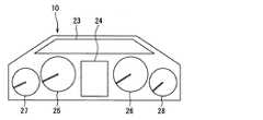
第1実施形態の色度補正装置100について、図1〜図6に基づいて説明する。色度補正装置100は、検査対象となる製品の光源部20における複数の光源が同時に点灯されたときの混色の色度を、各光源同士の光度比が予め定めた光度比(設計光度比)における目標色の色度に近づくように補正する装置である。ここでは、検査対象となる製品として、例えば、車両用のメータ装置10としている。色度補正装置100は、メータ装置10に設けられた文字板照明部23(あるいは表示器24)等を照明する光源21、22(あるいは光源201、202、203)による混色の色度を補正するようにしている。(First embodiment)
The chromaticity correction apparatus 100 of 1st Embodiment is demonstrated based on FIGS. The chromaticity correction apparatus 100 determines the chromaticity of the mixed colors when a plurality of light sources in the
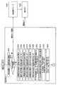
まず、メータ装置10について簡単に説明する。メータ装置10は、車両の走行時における各種車両情報を乗員に対して総合的に表示する装置である。メータ装置10の外観は、乗員側から見て、図1に示すようになっており、例えば、文字板に文字板照明部23、表示器24、速度計25、回転計26、燃料残量計27、および水温計28等が設けられている。 First, the
文字板照明部23は、透光性の板状を成しており、例えば、発光色の異なる複数の光源21、22によって得られる混色(中間色)が透過されることによって照明される部位となっている。表示器24は、例えば、薄膜トランジスタ(TFT)を用いた液晶式ディスプレイであり、車両の各種情報(走行距離、燃費、航続距離、外気温度等)を表示するようになっている。速度計25は、車両の走行速度を表示する指針式の計器である。回転計26は、エンジンの回転数を表示する指針式の計器である。燃料残量計27は、燃料タンク内の燃料の残量を表示する指針式の計器である。また、水温計28は、エンジンの冷却水の温度を表示する指針式の計器である。 The
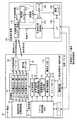
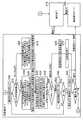
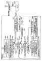
そして、メータ装置10の内部には、図2に示すように、インターフェイス11、電源回路12、システム制御回路13、点灯制御部14、表示制御部15、記憶保持部16、警告灯駆動部17、ステッパモータ18、電流設定部19、および光源部20等が設けられている。 As shown in FIG. 2, the
インターフェイス11は、実車装着時における各種車両機器とシステム制御回路13とを繋ぐ、あるいは、実車装着前の色度補正時における色度補正装置100とシステム制御回路13とを繋ぐ接続手段である。インターフェイス11は、実車装着時においては、各種車両機器からの製品制御信号等を受け入れるようになっている。また、インターフェイス11は、色度補正時においては、色度補正装置100から出力される色度補正モード信号等を受け入れるようになっている。 The interface 11 is a connection unit that connects various vehicle devices and the
電源回路12は、実車装着時において車両バッテリからメータ装置10の内部回路に電源供給する、あるいは色度補正時において色度補正装置100の電源150からメータ装置10の内部回路に電源供給する回路である。 The
システム制御回路13は、インターフェイス11から出力される出力信号に基づいて、実車装置時における製品機能の制御(製品動作モード)と、色度補正時における色度補正の制御(色度補正モード)とを切替え可能として総合的に実行する制御回路となっている。システム制御回路13は、例えば、点灯制御部14、表示制御部15、記憶保持部16、警告灯駆動部17、ステッパモータ18、および電流設定部19等に対して制御用の指示を与える(制御信号を出力する)ようになっている。 Based on the output signal output from the interface 11, the
点灯制御部14は、トランジスタによるスイッチ回路から形成された制御部であり、光源部20における各光源21、22、201、202、203の作動(点灯、消灯)を制御するようになっている。 The
表示制御部15は、各種車両機器からの製品制御信号等に基づいて、表示器24の表示状態(表示内容)を制御する制御部となっている。 The display control unit 15 is a control unit that controls the display state (display contents) of the
記憶保持部16は、後述する色度補正のための電流補正値を記憶保持する保持部であり、実車装着時における各光源21、22、201、202、203に対する駆動電流の設定に反映するようになっている。記憶保持部16は、例えば、EEPROM等が採用されている。 The
警告灯駆動部17は、各種車両機器からの製品制御信号に基づいて、乗員に対する注意、警告等を示すための警告灯17aの点灯、消灯の制御を行う駆動部となっている。 The warning light drive unit 17 is a drive unit that controls the turning on and off of the
ステッパモータ18は、各種車両機器からの製品制御信号に基づいて、速度計25、回転計26、燃料残量計27、および水温計28の各指針を回動させるモータである。 The
電流設定部19は、色度補正装置100の色度補正部120、およびシステム制御回路13からの指示(電流補正値による補正指示)に基づき、光源部20における各光源21、22、201、202、203に供給する駆動電流を設定する定電流回路である。 The
光源部20は、文字板照明部23、および表示器24を照明するための複数の光源21、22、201、202、203を備えている。各光源21、22、201、202、203は、例えば、発光ダイオード(LED)が使用されている。各光源21、22、201、202、203は、点灯制御部14によって、点灯、消灯状態が制御される。更に、電流設定部19によって設定される駆動電流に応じて、光度(明るさ)が調整されるようになっている。 The
光源21、22は、乗員とは反対側から発光して文字板照明部23を照明するための光源となっている。光源21は、第1の色として青色に発光する光源となっている。また、光源22は、第2の色として赤色に発光する光源となっている。文字板照明部23は、光源21と光源22とが同時に点灯されることで得られる混色(青紫色)によって照明されるようになっている。尚、本第1実施形態では上記光源21、22を用いた場合の色度補正について説明する。光源21は、本発明の第1光源に対応し、光源22は、本発明の第2光源に対応する。 The
また、光源201、202、203は、表示器24のバックライトとして使用される光源となっている。光源201は、第1の色として青色に発光する光源となっている。また、光源202は、第2の色として赤色に発光する光源となっている。更に、光源203は、第3の色として緑色に発光する光源となっている。表示器24は、光源201、202、230が同時に点灯されることで得られる混色(白色)によって照明されるようになっている。尚、光源201、202、203を用いた場合の色度補正については、以下の第2実施形態にて説明することとする。 The
次に、色度補正装置100について同様に図2を用いて説明する。色度補正装置100は、色度検出部110、色度補正部120、モニタ130、インターフェイス140、および電源150等を備えている。 Next, the chromaticity correction apparatus 100 will be described with reference to FIG. The chromaticity correction apparatus 100 includes a
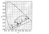
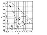
色度検出部110は、各光源21、22(201、202、203)の少なくとも1つが点灯したときのそれぞれの色度を検出する検出部である。つまり、色度検出部110は、光源21、22(201、202、203)の単体での点灯時の色度、および複数の光源21、22(201、202、203)の同時点灯時の色度を検出可能となっている。色度検出部110としては、例えば、カラーカメラ、あるいは色度計が使用される。色度検出部110によって検出される色度は、図3に示す色度図上におけるx座標位置およびy座標位置として検出されるものである。色度検出部110は、検出した色度データを色度補正部120に出力するようになっている。 The
ここで、色度図というのは、国際照明委員会にて設定されたもので、光の色をx、yの平面(2次元)座標で表すようにした図である。色度図においては、色のスペクトル軌跡によって座標中の左上側に向けて凸となる曲線部分が示されており、この曲線上には、波長に応じた各種単色(青〜赤までの各種単色)が位置するようになっている。曲線部分の左下側は青色に対応し、曲線部分の凸部は緑色に対応し、曲線部分の右下側は赤色に対応している。そして、曲線部分の内側の領域は、各単色が混合された色に対応するようになっている。例えば、青色と赤色との中間領域は青紫となっている。また、曲線部分の内側の中央領域は、青、緑、赤が混合された白色となっている。 Here, the chromaticity diagram is set by the International Commission on Illumination, and is a diagram in which the color of light is represented by plane (two-dimensional) coordinates of x and y. In the chromaticity diagram, a curved portion that protrudes toward the upper left side of the coordinates by the spectral locus of the color is shown, and on this curve, various single colors according to the wavelength (various single colors from blue to red) ) Is located. The lower left side of the curved portion corresponds to blue, the convex portion of the curved portion corresponds to green, and the lower right side of the curved portion corresponds to red. And the area | region inside a curve part respond | corresponds to the color in which each single color was mixed. For example, the middle region between blue and red is bluish purple. Further, the central region inside the curved portion is white in which blue, green, and red are mixed.
色度検出部110としてカラーカメラを用いた場合は、比較的広い範囲での色度検出が可能であるが、色度計を用いた場合であると、比較的狭い範囲での色度検出となる。よって、色度補正装置100に、色度検出部110を保持する保持部111と、保持部111を移動させる移動部112を設けるようにしても良い。移動部112は、色度補正部120によって作動制御される。この保持部111と移動部112とによって、色度検出したい所定範囲の中で、色度検出部110を移動させながら、移動ポイントごとに色度を検出していくことが可能となる。 When a color camera is used as the
色度補正部120は、色度検出部110から得られた色度データに基づいて、各光源21、22(201、202、203)が同時点灯されたときの混色の色度が、目標色の色度に近づくように電流補正値を算出する。更に、色度補正部120は、メータ装置10のシステム制御回路13、電流設定部19に対して各光源21、22(201、202、203)に供給する駆動電流を変更するようになっている。色度補正部120の詳細作動については、後述する。 Based on the chromaticity data obtained from the
モニタ130は、色度補正時の補正結果、あるいは補正がうまくできなかった場合の補正異常等を表示する表示部であり、色度補正部120によって作動制御されるようになっている。 The
インターフェイス140は、色度補正装置100とメータ装置10(インターフェイス11)とを繋ぐ接続手段である。インターフェイス140は、色度補正部120からの色度補正モード信号、および電流補正値等をメータ装置10に出力する。 The
電源150は、例えば、定格13.5Vの直流電源であり、色度補正時に色度補正部120の指示により、各光源21、22(201、202、203)に供給する電圧の出力(設定)を、制御するようになっている。 The
メータ装置10、および色度補正装置100の構成は以上のようになっている。以下、図4〜図6を加えて、色度補正装置100が行う色度補正の制御内容について説明する。本第1実施形態では、文字板照明部23を照明する2つの光源21、22による混色の色度補正について説明する。尚、文字板照明部23に対する色度検出のための測定位置は、複数個所について行うものとしている。 The configurations of the
まず、メータ装置10と色度補正装置100とが、インターフェイス11および140間で接続されると、図4、図5のフローチャートのステップS100で、色度補正部120は、電源150からメータ装置10に対して13.5Vの電源供給を開始する。 First, when the
そして、上記電源供給に伴い、色度補正部120は、システム制御回路13に色度補正モード信号を送信するようにしている。ステップS110で、所定時間内に色度補正モード信号が送信された場合であると、メータ装置10は色度補正モードとなる。この場合、色度補正部120は、以下のステップS140に進む。しかしながら、ステップS110で、所定時間内に色度補正モード信号が送信されていない場合であれば、色度補正モードは解除状態とされて、ステップS120で、メータ装置10は製品動作モードとなる。そして、ステップS130で、色度補正は終了となる。 The
ステップS140では、色度補正部120は、移動部112によって、色度検出部110を、複数の色度測定位置のうちの1つめの位置に移動させる。 In step S140, the
次に、ステップS150で、色度補正部120は、メータ装置10に対して、初期設定の駆動電流にて光源21を単体状態で点灯するように要求する。光源21における初期設定の駆動電流とは、光源21および光源22における光度比を予め定めた光度比にしたときに得られる混色の色度が、狙いとする目標色の色度Ps(Xs、Ys)となるように、光源21に対して設定された駆動電流である。目標色の色度Psは、図3の色度図上において、ポイントPsとして表示されている。 Next, in step S150, the
次に、ステップS160で、色度補正部120は、色度検出部110に対して、光源21の単体状態での点灯時の色度P1を計測させる。色度検出部110は、光源21の単体状態の色度P1を色度図上の座標(X1、Y1)として計測して、計測したデータを色度補正部120に出力する。光源21の単体状態の色度P1は、本発明の第1色度に対応する。以下、光源21の単体状態の色度P1を、第1色度P1と呼ぶことにする。第1色度P1は、図3の色度図上において、ポイントP1として表示される。 Next, in step S160, the
次に、ステップS170で、色度補正部120は、メータ装置10に対して、初期設定の駆動電流にて光源22を単体状態で点灯するように要求する。光源22における初期設定の駆動電流とは、上記の光源21の場合と同様に、光源21および光源22における光度比を予め定めた光度比にしたときに得られる混色の色度が、狙いとする目標色の色度Ps(Xs、Ys)となるように、光源22に対して設定された駆動電流である。 Next, in step S170, the
次に、ステップS180で、色度補正部120は、色度検出部110に対して、光源22の単体状態での点灯時の色度P2を計測させる。色度検出部110は、光源22の単体状態の色度P2を色度図上の座標(X2、Y2)として計測して、計測したデータを色度補正部120に出力する。光源22の単体状態の色度P2は、本発明の第2色度に対応する。以下、光源22の単体状態の色度P2を、第2色度P2と呼ぶことにする。第2色度P2は、図3の色度図上において、ポイントP2として表示される。 Next, in step S180, the
次に、ステップS190で、色度補正部120は、メータ装置10に対して、それぞれの初期設定の駆動電流にて光源21、22を同時に点灯するように要求する。 Next, in step S190, the
次に、ステップS200で、色度補正部120は、色度検出部110に対して、光源21、22の同時点灯による色度Pmを計測させる。色度検出部110は、光源21、22の同時点灯による色度Pmを色度図上の座標(Xm、Ym)として計測して、計測したデータを色度補正部120に出力する。光源21、22の同時点灯による色度Pmは、本発明の混色の色度に対応する。以下、光源21、22の同時点灯による色度Pmを、混色の色度Pmと呼ぶことにする。混色の色度Pmは、第1色度P1(光源21)と第2色度P2(光源22)とによって得られるものであり、図3の色度図上において、第1色度P1と第2色度P2とを通る直線L1上で、第1色度P1と第2色度P2との中間部に位置するポイントPmとして表示される。 Next, in step S200, the
次に、ステップS210で、色度補正部120は、混色の色度Pmと目標色の色度Psとの差ΔPmを求める。差ΔPmは、実際に得られた混色の色度Pmが、目標色の色度Psに近いものとして得られたか否かを判定するための判定量となる。差ΔPmは、各色度Pm、Psの座標位置の差から得ることができる。差ΔPmは、(Xm−Xs、Ym−Ys)として算出することができる。 Next, in step S210, the
次に、ステップS220で、色度補正部120は、差ΔPmの絶対値が、予め定めた所定規格値R2aより小さいか否かを判定する。色度補正部120は、ステップS220で、差ΔPmが所定規格値R2a以下であると判定すると、混色の色度Pmは、目標色の色度Psに充分近いものとして判定する。よって、色度補正部120は、光源21、22に対する初期設定の駆動電流の補正を行うことなしに、ステップS230で、駆動電流に対する補正値α1を1と設定する。 Next, in step S220, the
そして、ステップS240で、色度補正部120は、記憶保持部16に補正値α1(=1)を保存させる。そして、色度補正部120は、色度補正モードを解除する。これにより、メータ装置10は製品動作モードとなる(ステップS120)。 In step S240, the
一方、ステップS220で、色度補正部120は、差ΔPmが所定規格値R2aより大きいと判定すると、混色の色度Pmは、目標色の色度Psに近いものになっていないと判定し、ステップS250に進む。 On the other hand, if the
ステップS250では、色度補正部120は、直線L1上における線上の目標色度Pcを算出する。本来、目標色の色度Psは、直線L1上に乗るべきものであるが、実際には、光源21、22の光度狙い値に対するバラツキ等が発生することから、直線L1上に乗らない場合が発生し得る。よって、色度補正部120は、直線L1上での色度補正が可能となるように、色度図において、第1色度P1、混色の色度Pm、およびと第2色度P2を通る直線L1上において、目標色の色度Psの位置から直線L1上で最も近い位置を線上の目標色度Pcとして算出する。線上の目標色度Pcは、実質的には目標色の色度Psに近いものである。 In step S250, the
具体的には、色度図において、目標色の色度Psの座標位置から直線L1に垂線を下ろし、直線L1と垂線との交点を線上の目標色度Pc(Xc、Yc)として算出する。実際には、色度補正部120は、第1色度P1、第2色度P2、および目標色の色度Psの座標情報から得られる関数f1(P1、P2、Ps)を用いて線上の目標色度Pcを算出するようにしている。 Specifically, in the chromaticity diagram, a perpendicular line is drawn from the coordinate position of the chromaticity Ps of the target color to the straight line L1, and the intersection of the straight line L1 and the perpendicular line is calculated as the target chromaticity Pc (Xc, Yc) on the line. Actually, the
次に、ステップS260で、色度補正部120は、以下のステップS400で実施する補正回数カウントのために、まず、補正カウンタをクリアする。即ち、ここでは、補正回数カウントN1をゼロに設定する。 Next, in step S260, the
そして、ステップS270で、色度補正部120は、混色の色度Pmと線上の目標色度Pcとの座標位置を比較する。即ち、直線L1上において、混色の色度Pmが第1色度P1と線上の目標色度Pcとの間にあるか、あるいは、混色の色度Pmが線上の目標色度Pcと第2色度P2との間にあるかを判定する。混色の色度Pmが第1色度P1と線上の目標色度Pcとの間にある場合は、第1色度P1の光度が、第2色度P2の光度よりも高いことを意味する。逆に、混色の色度Pmが線上の目標色度Pcと第2色度P2との間にある場合は、第2色度P2の光度が、第1色度P1の光度よりも高いことを意味する。 In step S270, the
上記ステップS270の判定に基づいて、色度補正部120は、ステップS280、S290にて、あるいは、ステップS300、S310にて、光源21、あるいは光源22のうち、一方の光源の駆動電流の補正を行う。駆動電流の補正にあたっては、光源21、あるいは光源22のうち、光度の高い方の光源の初期の駆動電流を下げる方向で補正する。そして、この駆動電流の補正を実施するにあたって、本実施形態では、「色度距離」という概念を採用して、対応するようにしている。 Based on the determination in step S270, the
ここで、色度距離、および駆動電流の補正要領について、図6を用いて説明する。まず、本実施形態では、色度距離とは、色度座標空間上の任意の2つの色度間における距離と定義している。 Here, the procedure for correcting the chromaticity distance and the drive current will be described with reference to FIG. First, in this embodiment, the chromaticity distance is defined as a distance between any two chromaticities on the chromaticity coordinate space.
図6のグラフは、横軸に各色度(P1、P2、Pm、Pc)間の色度距離を示し、縦軸に第1色度P1と第2色度P2との光度比を示したものとなっている。横軸には、図3における直線L1上の各色度の位置関係を維持した形で、横軸左側に第1色度P1がプロットされ、また横軸右側に第2色度P2がプロットされる。また、横軸の第1色度P1と第2色度P2との間には、目標色度Pc、および線上の混色の色度Pmがプロットされる。In the graph of FIG. 6, the horizontal axis indicates the chromaticity distance between each chromaticity (P1, P2, Pm, Pc), and the vertical axis indicates the luminous intensity ratio between the first chromaticity P1 and the second chromaticity P2. It has become. On the horizontal axis, the first chromaticity P1 is plotted on the left side of the horizontal axis, and the second chromaticity P2 is plotted on the right side of the horizontal axis, while maintaining the positional relationship of each chromaticity on the straight line L1 in FIG. . Further, between the first chromaticity P1 and the second chromaticity P2 on the horizontal axis, thetarget chromaticity Pc and themixed color chromaticity Pm on the line are plotted.
上記横軸上において、第1色度P1と目標色度Pcとの間の距離が色度距離mとなり、第2色度P2と目標色度Pcとの間の距離が色度距離nとなる。また、第1色度P1と混色の色度Pmとの間の距離が色度距離ma(あるいはmb)となり、第2色度P2と混色の色度Pmとの間の距離が色度距離na(あるいはnb)となる。On the horizontal axis, the distance between the first chromaticity P1 and thetarget chromaticity Pc is the chromaticity distance m, and the distance between the second chromaticity P2 and thetarget chromaticity Pc is the chromaticity distance n. . Further, the distance between the first chromaticity P1 and the mixed color chromaticity Pm is the chromaticity distance ma (or mb), and the distance between the second chromaticity P2 and the mixed color chromaticity Pm is the chromaticity distance na. (Or nb).
色度距離mは本発明の第1目標色度距離に対応する。また、色度距離nは本発明の第2目標色度距離に対応する。また、色度距離ma(あるいはmb)は本発明の第1色度距離に対応する。また、色度距離na(あるいはnb)は本発明の第2色度距離に対応する。 The chromaticity distance m corresponds to the first target chromaticity distance of the present invention. The chromaticity distance n corresponds to the second target chromaticity distance of the present invention. The chromaticity distance ma (or mb) corresponds to the first chromaticity distance of the present invention. The chromaticity distance na (or nb) corresponds to the second chromaticity distance of the present invention.
ここで、横軸上における第1色度P1における位置は、光源21の単体状態での点灯時を意味しており、この位置に対する縦軸の光度比は、光源21単体の光度を1と設定した値がプロットされる。また、第2色度P2における位置は、光源22の単体状態での点灯時を意味しており、この位置に対する縦軸の光度比は、光源22単体の光度を1と設定した値がプロットされる。そして、第1色度P1の光度比ゼロの点と、第2色度P2の光度比1の点とを繋ぐ直線が、光源21と光源22との光度比が変化された場合の、光度比を示す直線となる。 Here, the position at the first chromaticity P1 on the horizontal axis means when the light source 21 is lit in a single state, and the luminous intensity ratio of the vertical axis with respect to this position sets the luminous intensity of the light source 21 alone to 1. The values are plotted. The position at the second chromaticity P2 means that the
具体的には、例えば、横軸の目標色度Pcの位置において、UIv1が光源21の光度であり、UIv2が光源22の光度である。両光度の関係は、UIv1+UIv2=1と規格化されており、UIv1/UIv2が光度比となる。Specifically, for example, at the position of thetarget chromaticity Pc on the horizontal axis, UIv1 is the luminous intensity of the light source 21, and UIv2 is the luminous intensity of the
よって、上記で説明した図6より、2つの光源21、22の光度比を色度距離で表すことができる。即ち、目標色度Pcにおける光度比UIv1/UIv2は、色度距離の比n/mとして表すことができる。同様に、図6(a)において、混色の色度Pmにおける光度比UIv1a/UIv2aは、色度距離の比na/maとして表すことができる。同様に、図6(b)においては、混色の色度Pmにおける光度比UIv1b/UIv2bは、色度距離の比nb/mbとして表すことができる。Therefore, from FIG. 6 described above, the luminous intensity ratio of the two
上記の考え方を基にして、ステップS270にて、色度補正部120は、直線L1上において、混色の色度Pmが第1色度P1と線上の目標色度Pcとの間にあると判定すると、第1色度P1の光度が、第2色度P2の光度より高いことから、ステップS280に進む。ステップS280では、光源21と光源22のうち、光度の高い方の光源21の光度を下げるための電流補正値αaを算出する。電流補正値αaは、1より小さい値とするものである。電流補正値αaは、本発明の補正係数に対応する。 Based on the above concept, in step S270, the
具体的には、ステップS280では、図6(a)に示す色度距離の比na/maを色度距離の比n/mに近づけるようにする。 Specifically, in step S280, the chromaticity distance ratio na / ma shown in FIG. 6A is made closer to the chromaticity distance ratio n / m.
つまり、目標色度Pcにおける光度比は、
(数1)
UIv1:UIv2=n:m であり、
混色の色度Pmにおける光度比は、
(数2)
UIv1a:UIv2a=na:ma となる。That is, the luminous intensity ratio at thetarget chromaticity Pc is
(Equation 1)
UIv1: UIv2 = n: m
The luminous intensity ratio in the mixed color chromaticity Pm is
(Equation 2)
UIv1a: UIv2a = na: ma
よって、混色の色度Pmの光度比におけるUIv1aに対して、αa(<1)倍の補正をして、上記数式1を実現するためには、
(数3)
(αa・UIv1a):UIv2a=UIv1:UIv2 とすることが必要となる。Therefore, in order to realize the
(Equation 3)
(Αa · UIv1a): UIv2a = UIv1: UIv2 is required.
上記数式3より、
(αa・UIv1a)・UIv2=UIv1・UIv2a となり、
よって、
αa=(UIv1/UIv2)・(UIv2a/UIv1a) となり、
これに、上記数式1、数式2を代入すると、
(数4)
αa=(n/m)・(ma/na) となる。つまり、電流補正値αaは、色度距離m、n、ma、naによって算出可能となる。From
(Αa · UIv1a) · UIv2 = UIv1 · UIv2a
Therefore,
αa = (UIv1 / UIv2) · (UIv2a / UIv1a)
Substituting the
(Equation 4)
αa = (n / m) · (ma / na) That is, the current correction value αa can be calculated from the chromaticity distances m, n, ma, na.
ステップS280の初回処理のときは、電流補正値αa=(n/m)・(ma/na)として算出する。また、後述するステップS410の後の2回め以降の処理では、電流補正値αa=(先回のαa)・(ma/na)として算出する。 In the initial processing in step S280, the current correction value αa = (n / m) · (ma / na) is calculated. In the second and subsequent processes after step S410, which will be described later, the current correction value αa = (previous αa) · (ma / na) is calculated.
そして、ステップS290で、色度補正部120は、メータ装置10のシステム制御回路13に対して、光源21に対する駆動電流値をαa倍とする電流設定変更の要求を指示する。 In step S290, the
一方、ステップS270にて、色度補正部120は、直線L1上において、混色の色度Pmが線上の目標色度Pcと第2色度P2との間にあると判定すると、第2色度P2の光度が、第1色度P1の光度より高いことから、ステップS300に進む。ステップS300では、光源21と光源22のうち、光度の高い方の光源22の光度を下げるための電流補正値αbを算出する。電流補正値αbは、1より小さい値とするものである。電流補正値αbは、本発明の補正係数に対応する。 On the other hand, when the
具体的には、ステップS300は、図6(b)に示す色度距離の比nb/mbを色度距離の比n/mに近づけるようにする。 Specifically, in step S300, the chromaticity distance ratio nb / mb shown in FIG. 6B is made closer to the chromaticity distance ratio n / m.
つまり、目標色度Pcにおける光度比は、上記のとおり、
(数1)
UIv1:UIv2=n:m であり、
混色の色度Pmにおける光度比は、
(数5)
UIv1b:UIv2b=nb:mb となる。That is, the luminous intensity ratio at thetarget chromaticity Pc is as described above.
(Equation 1)
UIv1: UIv2 = n: m
The luminous intensity ratio in the mixed color chromaticity Pm is
(Equation 5)
UIv1b: UIv2b = nb: mb
よって、混色の色度Pmの光度比におけるUIv2bに対して、αb(<1)倍の補正をして、上記(1)式を実現するためには、
(数6)
UIv1b:(αb・UIv2b)=UIv1:UIv2 とすることが必要となる。Therefore, in order to realize the above equation (1) by correcting the UIv2b in the luminous intensity ratio of the mixed color chromaticity Pm by αb (<1) times,
(Equation 6)
UIv1b: (αb · UIv2b) = UIv1: UIv2 is required.
上記数式6より、
(αb・UIv2b)・UIv1=UIv2・UIv1b となり、
よって、
αb=(UIv2/UIv1)・(UIv1b/UIv2b) となり、
これに、上記数式1、数式5を代入すると、
(数7)
αb=(m/n)・(nb/mb) となる。つまり、電流補正値αbは、色度距離m、n、mb、nbによって算出可能となる。From Equation 6 above,
(Αb · UIv2b) · UIv1 = UIv2 · UIv1b
Therefore,
αb = (UIv2 / UIv1) · (UIv1b / UIv2b)
Substituting the
(Equation 7)
αb = (m / n) · (nb / mb) That is, the current correction value αb can be calculated from the chromaticity distances m, n, mb, and nb.
ステップS300の初回処理のときは、電流補正値αb=(m/n)・(nb/mb)として算出する。また、後述するステップS410の後の2回め以降の処理では、電流補正値αb=(先回のαb)・(nb/mb)として算出する。 In the first processing in step S300, the current correction value αb is calculated as (m / n) · (nb / mb). In the second and subsequent processes after step S410 described later, the current correction value αb = (previous αb) · (nb / mb) is calculated.
そして、ステップS310で、色度補正部120は、メータ装置10のシステム制御回路13に対して、光源22に対する駆動電流値をαb倍とする電流設定変更の要求を指示する。 In step S <b> 310, the
次に、ステップS320で、色度補正部120は、メータ装置10に対して、補正した後の駆動電流にて光源21、22を同時に点灯するように要求する。 Next, in step S320, the
次に、ステップS330で、色度補正部120は、色度検出部110に対して、光源21、22の同時点灯による色度Pm(色度図上の座標(Xm、Ym))を計測させる。 Next, in step S330, the
次に、ステップS340で、色度補正部120は、混色の色度Pmと線上の目標色度Pcとの差ΔPmLを求める。差ΔPmLは、(Xm−Xc、Ym−Yc)として算出することができる。 Next, in step S340, the
次に、ステップS350で、色度補正部120は、差ΔPmLの絶対値が、予め定めた所定規格値R2bより小さいか否かを判定する。所定規格値R2bは、上記ステップS220における所定規格値R2aと同一値とすることができる。 Next, in step S350, the
色度補正部120は、ステップS350で、差ΔPmLが所定規格値R2b以下であると判定すると、混色の色度Pmは、線上の目標色度Pc、即ち、目標色の色度Psに充分近いものとして判定する。よって、色度補正部120は、ステップS360で、システム制御回路13に対して、光源21、22に対する電流補正値(αaあるいはαb)を記憶保持部16に書込みするように指示する。 If the
そして、ステップS370で、色度補正部120は、色度補正が正常に行われたものとして、1つめの色度補正点に対する色度補正を終了する。 In step S370, the
そして、ステップS380で、色度補正部120は、残りの色度補正点が有るか、否かを判定し、残りの色度補正点がある場合は、ステップS140に進み、上記と同様の制御を行う。また、ステップS380で、色度補正部120は、否と判定すれば、全ての色度補正点の補正が終了したことになり、色度補正モードを解除して、ステップS390で、メータ装置10を製品動作モードにする。 In step S380, the
一方、色度補正部120は、ステップS350で、差ΔPmLが所定規格値R2bよりも大きいと判定すると、混色の色度Pmは、線上の目標色度Pcに近いものになっていないと判定し、ステップS400に進む。On the other hand, if the
ステップS400では、色度補正部120は、補正回数カウントN1をN1+1とし、ステップS410で、補正回数カウントN1が3回より大きいか否かを判定する。補正回数カウントN1が3回以下であると、まだ、色度補正の余地があると判定して、色度補正部120は、ステップS270に戻り、ステップS270〜ステップS400を繰り返す。つまり、光源21、22に対する電流補正値の算出を行い、混色の色度Pmの補正を繰り返す。 In step S400, the
しかしながら、ステップS410で、補正回数カウントN1が3回を超えると、これ以上、色度補正の余地が無いと判定して、色度補正部120は、ステップS420で、色度補正を行わずに、異常終了とする。このとき、色度補正部120は、モニタ130に、色度補正の異常終了を表示させると共に、色度補正モードを解除する。 However, if the correction count N1 exceeds 3 in step S410, it is determined that there is no more room for chromaticity correction, and the
以上のように、本第1実施形態の色度補正装置100では、2つの光源21、22の混色の色度Pmを目標色の色度Psに近づけるように補正するにあたって、まず、色度検出部110によって、光源21単体の第1色度P1、光源22単体の第2色度P2、および光源21、22による混色の色度Pmを検出する。 As described above, in the chromaticity correction apparatus 100 according to the first embodiment, when correcting the mixed color chromaticity Pm of the two
そして、目標色の色度Psから線上の目標色度Pcを算出する。更に、色度座標空間上における色度距離という概念を新たに定義して、混色の色度Pmが線上の目標色度Pcに近づくように、各色度P1、P2、Pm、Pcにかかる色度距離m、n、ma(mb)、na(nb)を基に、光源21、22に供給する駆動電流の電流補正値αa(数式4)、あるいは電流補正値αb(数式7)を算出する。 Then, the target chromaticity Pc on the line is calculated from the chromaticity Ps of the target color. Further, the concept of chromaticity distance in the chromaticity coordinate space is newly defined, and the chromaticity applied to each chromaticity P1, P2, Pm, and Pc so that the chromaticity Pm of the mixed color approaches the target chromaticity Pc on the line. Based on the distances m, n, ma (mb), and na (nb), the current correction value αa (Formula 4) or the current correction value αb (Formula 7) of the drive current supplied to the
そして、得られた電流補正値に基づいて駆動電流を変更して、混色の色度Pmを線上の目標色度Pcに、即ち、目標色の色度Psに近づけるように補正している。 Then, the drive current is changed based on the obtained current correction value, and the mixed color chromaticity Pm is corrected so as to approach the target chromaticity Pc on the line, that is, the chromaticity Ps of the target color.
よって、色度補正装置100は、検出した第1色度p1、第2色度P2、および混色の色度Pmを基に、各色度距離m、n、ma、mb、na、nbを算出し、更に、各色度距離を基に、駆動電流に対する電流補正値を算出することで、色度補正を行うことができる。つまり、従来技術のように、各光源21、22の光度ランクを予め所定ランクに選別しておく必要がない。また、従来技術のように、選別された各光源を用いた場合の色度補正データを事前に把握して、色度補正データ格納部に格納しておく必要もなく、よって、専用の格納部の設定も不要とすることができる。 Therefore, the chromaticity correction apparatus 100 calculates each chromaticity distance m, n, ma, mb, na, nb based on the detected first chromaticity p1, second chromaticity P2, and mixed color chromaticity Pm. Furthermore, chromaticity correction can be performed by calculating a current correction value for the drive current based on each chromaticity distance. That is, unlike the prior art, it is not necessary to preliminarily sort the light intensity ranks of the
また、電流補正値αa、αbを算出する際に、2つの光源21、22のうち、一方の光源の光度を変更することで、且つ、光度の高い方(色度距離の小さい方)の光度を下げることで、目標の色度が得られるようにしている。これにより、各光源21、22への駆動電流を色度補正のためにいたずらに増加させることがなく、耐久性等の悪化を伴うことがない。また、2つの光源21、22の一方の光度を変更することで、補正の手間を低減することが可能となる。 Further, when calculating the current correction values αa and αb, the luminous intensity of the higher one (the smaller chromaticity distance) is obtained by changing the luminous intensity of one of the two
また、光源21、22と色度検出部110との間に、文字板照明部23が介在されるような場合、文字板照明部23が1つのカラーフィルタとなる。このような場合であっても、カラーフィルタの影響を含んだ形で各色度を検出しているので、この色度に基づく色度距離を用いた色度補正が可能となっている。よって、光源の直接的な色度を検出する場合に限らず、メータ装置10のような製品の場合の色度補正が可能である。 When the
(第2実施形態)
第2実施形態について、図2、図7〜図12を用いて説明する。第2実施形態は、メータ装置10の表示器24を照明する3つの光源201、202、203による混色の色度を、色度補正装置100によって補正する場合の制御要領を示したものである。光源201は、本発明の第1光源に対応し、光源202は、本発明の第2光源に対応し、光源203は、本発明の第3光源に対応する。尚、メータ装置10、および色度補正装置100の各構成は、上記第1実施形態で説明した内容と同一である。(Second Embodiment)
A second embodiment will be described with reference to FIGS. 2 and 7 to 12. The second embodiment shows a control procedure when the chromaticity correction device 100 corrects the chromaticity of the mixed colors by the three
色度補正装置100が実施する制御内容について、図7〜図9のフローチャートに基づいて説明する。 The contents of control performed by the chromaticity correction apparatus 100 will be described based on the flowcharts of FIGS.
まず、メータ装置10と色度補正装置100とが、インターフェイス11および140間で接続されると、ステップS500で、色度補正部120は、電源150からメータ装置10に対して13.5Vの電源供給を開始する。 First, when the
そして、上記電源供給に伴い、色度補正部120は、システム制御回路13に色度補正モード信号を送信するようにしている。ステップS500で、所定時間内に色度補正モード信号が送信された場合であると、メータ装置10は色度補正モードとなる。この場合、色度補正部120は、以下のステップS540に進む。しかしながら、ステップS510で、所定時間内に色度補正モード信号が送信されていない場合であれば、色度補正モードは解除状態とされて、ステップS520で、メータ装置10は製品動作モードとなる。そして、ステップS530で、色度補正は終了となる。 The
次に、ステップS540で、色度補正部120は、メータ装置10に対して、初期設定の駆動電流にて光源201を単体状態で点灯するように要求する。光源201における初期設定の駆動電流とは、光源201、202、203における光度比を予め定めた光度比にしたときに得られる混色の色度が、狙いとする目標色の色度Pw(Xw、Yw)となるように、光源201に対して設定された駆動電流である。目標色の色度Pwは、図10の色度図上において、ポイントPwとして表示されている。 Next, in step S540, the
次に、ステップS550で、色度補正部120は、色度検出部110に対して、光源201の単体状態での点灯時の色度P1を計測させる。色度検出部110は、光源201の単体状態の色度P1を色度図上の座標(X1、Y1)として計測して、計測したデータを色度補正部120に出力する。光源201の単体状態の色度P1は、本発明の第1色度に対応する。以下、光源201の単体状態の色度P1を、第1色度P1と呼ぶことにする。第1色度P1は、図10の色度図上において、ポイントP1として表示される。 Next, in step S550, the
次に、ステップS560で、色度補正部120は、メータ装置10に対して、初期設定の駆動電流にて光源202を単体状態で点灯するように要求する。光源202における初期設定の駆動電流とは、上記の光源201の場合と同様に、光源201、202、203における光度比を予め定めた光度比にしたときに得られる混色の色度が、狙いとする目標色の色度Pw(Xw、Yw)となるように、光源202に対して設定された駆動電流である。 Next, in step S560, the
次に、ステップS570で、色度補正部120は、色度検出部110に対して、光源202の単体状態での点灯時の色度P2を計測させる。色度検出部110は、光源202の単体状態の色度P2を色度図上の座標(X2、Y2)として計測して、計測したデータを色度補正部120に出力する。光源202の単体状態の色度P2は、本発明の第2色度に対応する。以下、光源202の単体状態の色度P2を、第2色度P2と呼ぶことにする。第2色度P2は、図10の色度図上において、ポイントP2として表示される。 Next, in step S570, the
次に、ステップS580で、色度補正部120は、メータ装置10に対して、初期設定の駆動電流にて光源203を単体状態で点灯するように要求する。光源203における初期設定の駆動電流とは、上記の光源201の場合と同様に、光源201、202、203における光度比を予め定めた光度比にしたときに得られる混色の色度が、狙いとする目標色の色度Pw(Xw、Yw)となるように、光源203に対して設定された駆動電流である。 Next, in step S580, the
次に、ステップS590で、色度補正部120は、色度検出部110に対して、光源203の単体状態での点灯時の色度P3を計測させる。色度検出部110は、光源203の単体状態の色度P3を色度図上の座標(X3、Y3)として計測して、計測したデータを色度補正部120に出力する。光源203の単体状態の色度P3は、本発明の第3色度に対応する。以下、光源203の単体状態の色度P3を、第3色度P3と呼ぶことにする。第3色度P3は、図10の色度図上において、ポイントP3として表示される。 Next, in step S590, the
次に、ステップS600で、色度補正部120は、第1色度P1と第2色度P2とを結ぶ直線L1と、第3色度P3と目標色の色度Pwとを結ぶ直線L2を算出し、更に、直線L1と直線L2とが交差する点を第1線上の目標色度Pvとして算出する。第1線上の目標色度Pvは、光源201と光源202とが初期設定の駆動電流で点灯される場合に、狙い値(設計値)として想定される混色の色度である。 Next, in step S600, the
次に、ステップS610で、色度補正部120は、メータ装置10に対して、光源203は消灯状態にして、初期設定の駆動電流にて光源201、202の2つを点灯するように要求する。 Next, in step S610, the
次に、ステップS620で、色度補正部120は、色度検出部110に対して、光源201、202が点灯、光源203が消灯の状態での混色の色度Pm1を計測させる。色度検出部110は、混色の色度Pm1を色度図上の座標(Xm1、Ym1)として計測して、計測したデータを色度補正部120に出力する。混色の色度Pm1は、本発明の第1混色の色度に対応する。以下、光源201、202が点灯、光源203が消灯状態での混色の色度Pm1を、第1混色の色度Pm1と呼ぶことにする。第1混色の色度Pm1は、図10の色度図上において、ポイントPm1として表示される。 Next, in step S620, the
次に、ステップS630で、色度補正部120は、第1混色の色度Pm1と第1線上の目標色度Pvとの差ΔPm1を求める。差ΔPm1は、実際に得られた第1混色の色度Pm1が、第1線上の目標色度Pvに近いものとして得られたか否かを判定するための判定量となる。差ΔPm1は、各色度Pm1、Pvの座標位置の差から得ることができる。差ΔPm1は、(Xm1−Xv、Ym1−Yv)として算出することができる。 Next, in step S630, the
次に、ステップS640で、色度補正部120は、差ΔPm1の絶対値が、予め定めた所定規格値R3aより小さいか否かを判定する。色度補正部120は、ステップS640で、差ΔPm1が所定規格値R3a以下であると判定すると、第1混色の色度Pm1は、第1線上の目標色度Pvに充分近いものとして判定する。よって、色度補正部120は、光源201、202に対する初期設定の駆動電流の補正を行うことなしに、ステップS650で、駆動電流に対する補正値α1aを1と設定する。 Next, in step S640, the
一方、ステップS640で、色度補正部120は、差ΔPm1が所定規格値R3aより大きいと判定すると、第1混色の色度Pm1は、第1線上の目標色度Pvに近いものになっていないと判定し、ステップS660に進む。 On the other hand, if the
次に、ステップS660で、色度補正部120は、以下のステップS770で実施する補正回数カウントのために、まず、補正カウンタをクリアする。即ち、ここでは、補正回数カウントNc1をゼロに設定する。 Next, in step S660, the
そして、ステップS670で、色度補正部120は、第1混色の色度Pm1と第1線上の目標色度Pvとの座標位置を比較する。即ち、ステップS680で、色度補正部120は、直線L1上において、第1混色の色度Pm1が第1色度P1と第1線上の目標色度Pvとの間にあるか、あるいは、第1混色の色度Pm1が第1線上の目標色度Pvと第2色度P2との間にあるかを判定する。第1混色の色度Pm1が第1色度P1と第1線上の目標色度Pvとの間にある場合は、第1色度P1の光度が、第2色度P2の光度よりも高いことを意味する。逆に、第1混色の色度Pm1が第1線上の目標色度Pvと第2色度P2との間にある場合は、第2色度P2の光度が、第1色度P1の光度よりも高いことを意味する。In step S670, the
上記ステップS680にて、色度補正部120は、直線L1上において、第1混色の色度Pm1が第1色度P1と第1線上の目標色度Pvとの間にあると判定すると、第1色度P1の光度が、第2色度P2の光度より高いことから、ステップS690に進む。ステップS690では、光源201と光源202のうち、光度の高い方の光源201の光度を下げるための電流補正値α1aを算出する。電流補正値α1aは、1より小さい値とするものである。電流補正値α1aは、本発明の第1補正係数に対応する。 In step S680, when the
具体的には、ステップS690では、図11中のケース1に示すように、色度距離の比n1a/m1aを色度距離の比n1/m1に近づけるようにする。尚、図11において、各色度P1、P2、Pm1a(Pm1b)、およびPvにかかる色度距離は、上記第1実施形態で説明した図6と同様に、それぞれ、色度距離m1、n1、m1a、n1a、m1b、n1bと定義されている。また、図11中において、第1混色の色度Pm1については、ケース1と後述するケース2とで区別するために、ケース1では第1混色の色度をPm1aと表示し、ケース2では第1混色の色度をPm1bと表示している。 Specifically, in step S690, as shown in
色度距離m1は本発明の第1目標色度距離に対応する。また、色度距離n1は本発明の第2目標色度距離に対応する。また、色度距離m1a(あるいはm1b)は本発明の第1色度距離に対応する。また、色度距離n1a(あるいはn1b)は本発明の第2色度距離に対応する。 The chromaticity distance m1 corresponds to the first target chromaticity distance of the present invention. The chromaticity distance n1 corresponds to the second target chromaticity distance of the present invention. The chromaticity distance m1a (or m1b) corresponds to the first chromaticity distance of the present invention. The chromaticity distance n1a (or n1b) corresponds to the second chromaticity distance of the present invention.
第1線上の目標色度Pvにおける光度比は、
(数8)
UIv1:UIv2=n1:m1 であり、
第1混色の色度Pm1aにおける光度比は、
(数9)
UIv1a:UIv2a=n1a:m1a となる。The luminous intensity ratio at the target chromaticity Pv on the first line is
(Equation 8)
UIv1: UIv2 = n1: m1
The light intensity ratio in the chromaticity Pm1a of the first mixed color is
(Equation 9)
UIv1a: UIv2a = n1a: m1a
よって、第1混色の色度Pm1aの光度比におけるUIv1aに対して、α1a(<1)倍の補正をして、上記数式8を実現するためには、
(数10)
(α1a・UIv1a):UIv2a=UIv1:UIv2 とすることが必要となる。Therefore, in order to realize the above Equation 8 by correcting α1a (<1) times with respect to UIv1a in the luminous intensity ratio of the chromaticity Pm1a of the first mixed color,
(Equation 10)
(Α1a · UIv1a): UIv2a = UIv1: UIv2 is required.
上記数式10より、
(α1a・UIv1a)・UIv2=UIv1・UIv2a となり、
よって、
α1a=(UIv1/UIv2)・(UIv2a/UIv1a) となり、
これに、上記数式8、数式9を代入すると、
(数11)
α1a=(n1/m1)・(m1a/n1a) となる。つまり、電流補正値α1aは、色度距離m1、n1、m1a、n1aによって算出可能となる。From
(Α1a · UIv1a) · UIv2 = UIv1 · UIv2a
Therefore,
α1a = (UIv1 / UIv2) · (UIv2a / UIv1a)
Substituting the above formulas 8 and 9 into this,
(Equation 11)
α1a = (n1 / m1) · (m1a / n1a) That is, the current correction value α1a can be calculated from the chromaticity distances m1, n1, m1a, and n1a.
ステップS690の初回処理のときは、電流補正値α1a=(n1/m1)・(m1a/n1a)として算出する。また、後述するステップS780の後の2回め以降の処理では、電流補正値α1a=(先回のα1a)・(m1a/n1a)として算出する。 In the case of the initial process in step S690, the current correction value α1a = (n1 / m1) · (m1a / n1a) is calculated. Further, in the second and subsequent processes after step S780 described later, the current correction value α1a = (previous α1a) · (m1a / n1a) is calculated.
そして、ステップS700で、色度補正部120は、メータ装置10のシステム制御回路13に対して、光源201に対する駆動電流値をα1a倍とする電流設定変更の要求を指示する。 In step S <b> 700, the
一方、ステップS680にて、色度補正部120は、直線L1上において、第1混色の色度Pm1が第1線上の目標色度Pvと第2色度P2との間にあると判定すると、第2色度P2の光度が、第1色度P1の光度より高いことから、ステップS710に進む。ステップS710では、光源201と光源202のうち、光度の高い方の光源202の光度を下げるための電流補正値α1bを算出する。電流補正値α1bは、1より小さい値とするものである。電流補正値α1bは、本発明の第1補正係数に対応する。 On the other hand, when the
具体的には、ステップS710では、図11中のケース2に示すように、色度距離の比n1b/m1bを色度距離の比n1/m1に近づけるようにする。 Specifically, in step S710, as shown in case 2 in FIG. 11, the chromaticity distance ratio n1b / m1b is made closer to the chromaticity distance ratio n1 / m1.
第1線上の目標色度Pvにおける光度比は、上記と同様に、
(数8)
UIv1:UIv2=n1:m1 であり、
第1混色の色度Pm1bにおける光度比は、
(数12)
UIv1b:UIv2b=n1b:m1b となる。The luminous intensity ratio at the target chromaticity Pv on the first line is the same as above.
(Equation 8)
UIv1: UIv2 = n1: m1
The luminous intensity ratio in the chromaticity Pm1b of the first mixed color is
(Equation 12)
UIv1b: UIv2b = n1b: m1b
よって、第1混色の色度Pm1bの光度比におけるUIv2bに対して、α1b(<1)倍の補正をして、上記数式8を実現するためには、
(数13)
UIv1b:(α1b・UIv2b)=UIv1:UIv2 とすることが必要となる。Therefore, in order to realize the above Equation 8 by correcting α1b (<1) times with respect to UIv2b in the luminous intensity ratio of the chromaticity Pm1b of the first mixed color,
(Equation 13)
UIv1b: (α1b · UIv2b) = UIv1: UIv2 is required.
上記数式11より、
(α1b・UIv2b)・UIv1=UIv2・UIv1b となり、
よって、
α1b=(UIv2/UIv1)・(UIv1b/UIv2b) となり、
これに、上記数式8、数式12を代入すると、
(数14)
α1b=(m1/n1)・(n1b/m1b) となる。つまり、電流補正値α1bは、色度距離m1、n1、m1b、n1bによって算出可能となる。From Equation 11 above,
(Α1b · UIv2b) · UIv1 = UIv2 · UIv1b
Therefore,
α1b = (UIv2 / UIv1) · (UIv1b / UIv2b)
Substituting the above Equation 8 and
(Equation 14)
α1b = (m1 / n1) · (n1b / m1b) That is, the current correction value α1b can be calculated from the chromaticity distances m1, n1, m1b, and n1b.
ステップS710の初回処理のときは、電流補正値α1b=(m1/n1)・(n1b/m1b)として算出する。また、後述するステップS780の後の2回め以降の処理では、電流補正値α1b=(先回のα1b)・(n1b/m1b)として算出する。 In the case of the initial processing in step S710, the current correction value α1b = (m1 / n1) · (n1b / m1b) is calculated. In the second and subsequent processes after step S780 described later, the current correction value α1b = (previous α1b) · (n1b / m1b) is calculated.
そして、ステップS720で、色度補正部120は、メータ装置10のシステム制御回路13に対して、光源202に対する駆動電流値をα1b倍とする電流設定変更の要求を指示する。 In step S720, the
次に、ステップS730で、色度補正部120は、メータ装置10に対して、補正した後の駆動電流にて光源201、202を同時に点灯するように要求する。 Next, in step S730, the
次に、ステップS740で、色度補正部120は、色度検出部110に対して、光源201、202が点灯、光源203が消灯の状態での第1混色の色度Pm1を計測させる。色度検出部110は、第1混色の色度Pm1を色度図上の座標(Xm1、Ym1)として計測して、計測したデータを色度補正部120に出力する。 Next, in step S740, the
次に、ステップS750で、色度補正部120は、第1混色の色度Pm1と第1線上の目標色度Pvとの差ΔPm1を再度求める。差ΔPm1は、ステップS630と同様に、(Xm1−Xv、Ym1−Yv)として算出される。 Next, in step S750, the
次に、ステップS760で、色度補正部120は、ステップS640と同様に、差ΔPm1の絶対値が、予め定めた所定規格値R3aより小さいか否かを判定する。色度補正部120は、差ΔPm1が所定規格値R3aより大きいと判定すると、第1混色の色度Pm1は、第1線上の目標色度Pvに近いものになっていないと判定し、ステップS770に進む。 Next, in step S760, the
ステップS770では、色度補正部120は、補正回数カウントNc1をNc1+1とし、ステップS780で、補正回数カウントNc1が3回より大きいか否かを判定する。補正回数カウントNc1が3回以下であると、まだ、色度補正の余地があると判定して、色度補正部120は、ステップS660に戻り、ステップS660〜ステップS770を繰り返す。つまり、光源201、202に対する電流補正値の算出を行い、第1混色の色度Pm1の補正を繰り返す。 In step S770, the
しかしながら、ステップS780で、補正回数カウントNc1が3回を超えると、これ以上、色度補正の余地が無いと判定して、色度補正部120は、ステップS790で、色度補正を行わずに、異常終了とする。このとき、色度補正部120は、モニタ130に、色度補正の異常終了を表示させると共に、色度補正モードを解除する。 However, if the correction count Nc1 exceeds 3 in step S780, it is determined that there is no more room for chromaticity correction, and the
上記ステップS640〜ステップS790は、本発明の第1光源(光源201)と第2光源(光源202)とを点灯させたときの、補正係数(電流補正値α1a、α1b)を算出するための第1ステップに対応する。 Steps S640 to S790 are steps for calculating correction coefficients (current correction values α1a and α1b) when the first light source (light source 201) and the second light source (light source 202) of the present invention are turned on. Corresponds to one step.
一方、色度補正部120は、上記のステップS760で、差ΔPm1が所定規格値R3a以下であると判定すると、第1混色の色度Pm1は、第1線上の目標色度Pvに充分近いものとして判定し、ステップS800に進む。 On the other hand, if the
ステップS800では、色度補正部120は、メータ装置10に対して、初期設定の駆動電流にて光源203を点灯させると共に、補正した後の駆動電流にて光源201、202を点灯するように要求する。 In step S800, the
次に、ステップS810で、色度補正部120は、以下のステップS870で実施する補正回数カウントのために、まず、補正カウンタをクリアする。即ち、ここでは、補正回数カウントNc2をゼロに設定する。 Next, in step S810, the
次に、ステップS820で、色度補正部120は、色度検出部110に対して、光源201、202、203の同時点灯時の混色の色度Pm2を計測させる。色度検出部110は、混色の色度Pm2を色度図上の座標(Xm2、Ym2)として計測して、計測したデータを色度補正部120に出力する。混色の色度Pm2は、本発明の第2混色の色度に対応する。以下、光源201、202、203の同時点灯時の混色の色度Pm2を、第2混色の色度Pm2と呼ぶことにする。第2混色の色度Pm2は、図10の色度図上において、ポイントPm2として表示される。 Next, in step S820, the
次に、ステップS830で、色度補正部120は、第2混色の色度Pm2と目標色の色度Pwとの差ΔPm2を求める。差ΔPm2は、(Xm2−Xw、Ym2−Yw)として算出される。 Next, in step S830, the
次に、ステップS840で、色度補正部120は、差ΔPm2の絶対値が、予め定めた所定規格値R3bより小さいか否かを判定する。色度補正部120は、差ΔPm2が所定規格値R3b以下であると判定すると、第2混色の色度Pm2は、目標色の色度Pwに充分近いものとして判定し、ステップS850に進む。 Next, in step S840, the
ステップS850では、色度補正部120は、システム制御回路13に対して、光源201、202に対する電流補正値α1a、α1bを記憶保持部16に書込みするように指示する。尚、ステップS640、およびステップS840で共に、初回で規格領域以内の判定がされた場合は、実質の補正が行われないため、電流補正値α1a、α1bは、それぞれ1となる。 In step S850, the
そして、ステップS860で、色度補正部120は、補正結果をモニタ130に表示する。 In step S860, the
一方、ステップS840で、色度補正部120は、差ΔPm2が所定規格値R3bより大きいと判定すると、第2混色の色度Pm2は、目標色の色度Pwに近いものになっていないと判定し、ステップS870に進む。 On the other hand, if the
ステップS870では、色度補正部120は、補正回数カウントNc2をNc2+1とし、ステップS880で、補正回数カウントNc2が3回より大きいか否かを判定する。補正回数カウントNc2が3回を超えると、これ以上、色度補正の余地が無いと判定して、色度補正部120は、ステップS890で、色度補正を行わずに、異常終了とする。このとき、色度補正部120は、モニタ130に、色度補正の異常終了を表示させると共に、色度補正モードを解除する。 In step S870, the
上記ステップS880で、補正回数カウントNc2が3回以下であると、色度補正の余地があると判定して、色度補正部120は、ステップS900に進む。 In step S880, if the correction count Nc2 is 3 or less, it is determined that there is room for chromaticity correction, and the
そして、ステップS900で、色度補正部120は、第2混色の色度Pm2と目標色の色度Pwとの座標位置を比較する。即ち、ステップS910で、色度補正部120は、直線L2上において、第2混色の色度Pm2が第3色度P3と目標色の色度Pwとの間にあるか、あるいは、第2混色の色度Pm2が目標色の色度Pwと第1線上の目標色度Pvとの間にあるかを判定する。第2混色の色度Pm2が第3色度P3と目標色の色度Pwとの間にある場合は、第3色度P3の光度が、第1線上の目標色度Pvの光度よりも高いことを意味する。逆に、第2混色の色度Pm2が目標色の色度Pwと第1線上の目標色度Pvとの間にある場合は、第1線上の目標色度Pvの光度が、第3色度P3の光度よりも高いことを意味する。 In step S900, the
上記ステップS910にて、色度補正部120は、直線L2上において、第2混色の色度Pm2が第3色度P3と目標色の色度Pwとの間にあると判定すると、第3色度P3の光度が、第1線上の目標色度Pvの光度より高いことから、ステップS920に進む。ステップS920では、光源203と、光源201および光源202とのうち、光度の高い方の光源203の光度を下げるための電流補正値α2aを算出する。電流補正値α2aは、1より小さい値とするものである。電流補正値α2aは、本発明の第2補正係数に対応する。 In step S910, if the
具体的には、ステップS920では、図12中のケース3に示すように、色度距離の比n2a/m2aを色度距離の比n2/m2に近づけるようにする。尚、図12において、各色度P3、Pv、Pm2a(Pm2b)、およびPwにかかる色度距離は、上記第1実施形態で説明した図6と同様に、それぞれ、色度距離m2、n2、m2a、n2a、m2b、n2bと定義されている。また、図12中において、第2混色の色度Pm2については、ケース3と後述するケース4とで区別するために、ケース3では第2混色の色度をPm2aと表示し、ケース4では第2混色の色度をPm2bと表示している。 Specifically, in step S920, as shown in
色度距離m2は本発明の第3目標色度距離に対応する。また、色度距離n2は本発明の第4目標色度距離に対応する。また、色度距離m2a(あるいはm2b)は本発明の第3色度距離に対応する。また、色度距離n2a(あるいはn2b)は本発明の第4色度距離に対応する。 The chromaticity distance m2 corresponds to the third target chromaticity distance of the present invention. The chromaticity distance n2 corresponds to the fourth target chromaticity distance of the present invention. The chromaticity distance m2a (or m2b) corresponds to the third chromaticity distance of the present invention. The chromaticity distance n2a (or n2b) corresponds to the fourth chromaticity distance of the present invention.
目標色の色度Pwにおける光度比は、
(数15)
UIv3:UIvv=n2:m2 であり、
第2混色の色度Pm2aにおける光度比は、
(数16)
UIv3a:UIvva=n2a:m2a となる。The luminous intensity ratio at the chromaticity Pw of the target color is
(Equation 15)
UIv3: UIvv = n2: m2
The luminous intensity ratio in the chromaticity Pm2a of the second mixed color is
(Equation 16)
UIv3a: UIvva = n2a: m2a
よって、第2混色の色度Pm2aの光度比におけるUIv3aに対して、α2a(<1)倍の補正をして、上記数式15を実現するためには、
(数17)
(α2a・UIv3a):UIvva=UIv3:UIvv とすることが必要となる。Therefore, in order to realize the above Formula 15 by correcting α2a (<1) times with respect to UIv3a in the luminous intensity ratio of the chromaticity Pm2a of the second mixed color,
(Equation 17)
(Α2a · UIv3a): UIvva = UIv3: UIvv is required.
上記数式17より、
(α2a・UIv3a)・UIvv=UIv3・UIvva となり、
よって、
α2a=(UIv3/UIvv)・(UIvva/UIv3a) となり、
これに、上記数式15、数式16を代入すると、
(数18)
α2a=(n2/m2)・(m2a/n2a) となる。つまり、電流補正値α2aは、色度距離m2、n2、m2a、n2aによって算出可能となる。From Equation 17 above,
(Α2a · UIv3a) · UIvv = UIv3 · UIvva
Therefore,
α2a = (UIv3 / UIvv) · (UIvva / UIv3a)
Substituting the
(Equation 18)
α2a = (n2 / m2) · (m2a / n2a) That is, the current correction value α2a can be calculated from the chromaticity distances m2, n2, m2a, and n2a.
そして、ステップS930で、色度補正部120は、メータ装置10のシステム制御回路13に対して、光源203に対する駆動電流値をα2a倍とする電流設定変更の要求を指示する。 In step S930, the
一方、ステップS910にて、色度補正部120は、直線L2上において、第2混色の色度Pm2が目標色の色度Pwと第1線上の目標色度Pvとの間にあると判定すると、第1線上の目標色度Pvの光度が、第3色度P3の光度より高いことから、ステップS940に進む。ステップS940では、光源201および光源202と、光源203のうち、光度の高い方の光源201および光源202の光度を下げるための電流補正値α2bを算出する。電流補正値α2bは、1より小さい値とするものである。電流補正値α2bは、本発明の第2補正係数に対応する。 On the other hand, when the
具体的には、ステップS940では、図12中のケース4に示すように、色度距離の比n2b/m2bを色度距離の比n2/m2に近づけるようにする。 Specifically, in step S940, as shown in case 4 in FIG. 12, the chromaticity distance ratio n2b / m2b is made closer to the chromaticity distance ratio n2 / m2.
目標色の色度Pwにおける光度比は、上記と同様に、
(数15)
UIv3:UIvv=n2:m2 であり、
第2混色の色度Pm2bにおける光度比は、
(数19)
UIv3b:UIvvb=n2b:m2b となる。The luminous intensity ratio at the chromaticity Pw of the target color is similar to the above.
(Equation 15)
UIv3: UIvv = n2: m2
The luminous intensity ratio in the chromaticity Pm2b of the second mixed color is
(Equation 19)
UIv3b: UIvvb = n2b: m2b
よって、第2混色の色度Pm2bの光度比におけるUIvvbに対して、α2b(<1)倍の補正をして、上記数式15を実現するためには、
(数20)
UIv3b:(α2b・UIvvb)=UIv3:UIvv とすることが必要となる。Therefore, in order to realize the above Formula 15 by correcting α2b (<1) times with respect to UIvvb in the luminous intensity ratio of the chromaticity Pm2b of the second mixed color,
(Equation 20)
UIv3b: (α2b · UIvvb) = UIv3: UIvv is required.
上記数式20より、
(α2b・UIvvb)・UIv3=UIvv・UIv3b となり、
よって、
α2b=(UIvv/UIv3)・(UIv3b/UIvvb) となり、
これに、上記数式15、数式19を代入すると、
(数21)
α2b=(m2/n2)・(n2b/m2b) となる。つまり、電流補正値α2bは、色度距離m2、n2、m2b、n2bによって算出可能となる。From
(Α2b · UIvvb) · UIv3 = UIvv · UIv3b
Therefore,
α2b = (UIvv / UIv3) · (UIv3b / UIvvb)
Substituting the
(Equation 21)
α2b = (m2 / n2) · (n2b / m2b) That is, the current correction value α2b can be calculated from the chromaticity distances m2, n2, m2b, and n2b.
そして、ステップS950で、色度補正部120は、メータ装置10のシステム制御回路13に対して、第1線上の目標色度Pvを得るための光源201および光源202に対する駆動電流値をα2b倍とする電流設定変更の要求を指示する。 In step S950, the
次に、ステップS960で、色度補正部120は、メータ装置10に対して、補正した後の駆動電流にて光源201、202、203を点灯するように要求し、ステップS820〜ステップS960を繰り返す。 Next, in step S960, the
そして、色度補正部120は、ステップS820〜ステップS960を繰り返す中で、ステップS840で、差ΔPm2の絶対値が、予め定めた所定規格値R3bより小さいと判定すれば、ステップS850、ステップS860を経て、色度補正モードを解除して、製品動作モードに切替え(ステップS520)、補正を終了する(ステップS530)。また、色度補正部120は、ステップS820〜ステップS960を繰り返す中で、ステップS880で、補正回数カウントが3回を超える場合は、ステップS890を経て、色度補正モードを解除して、製品動作モードに切替え(ステップS520)、補正を終了する(ステップS530)。 If the
以上のように、本第2実施形態においても、上記第1実施形態と同様の効果を得ることができる。即ち、本第2実施形態の色度補正装置100では、3つの光源201、202、203の混色の色度Pm2を目標色の色度Pwに近づけるように補正するにあたって、まず、色度検出部110によって、光源201単体の第1色度P1、光源202単体の第2色度P2、光源203単体の第3色度P3、および光源201、202による第1混色の色度Pm1を検出する。そして、第1色度P1、第2色度P2、第3色度P3、および目標色の色度Pwから第1線上の目標色度Pvを算出する。 As described above, also in the second embodiment, the same effect as in the first embodiment can be obtained. That is, in the chromaticity correction apparatus 100 according to the second embodiment, when correcting the mixed color chromaticity Pm2 of the three
次に、ステップ1として、色度座標空間上における色度距離という概念を新たに定義して、第1混色の色度Pm1が第1線上の目標色度Pvに近づくように、各色度P1、P2、Pm1、Pvにかかる色度距離m1、n1、m1a(m1b)、n1a(n1b)を基に、光源201、202に供給する駆動電流の電流補正値α1a(数式11)、あるいは電流補正値α1b(数式14)を算出する。 Next, as
そして、得られた電流補正値に基づいて駆動電流を変更して、第1混色の色度Pm1を第1線上の目標色度Pvに近づけるように補正している。 Then, the drive current is changed based on the obtained current correction value to correct the chromaticity Pm1 of the first mixed color to be close to the target chromaticity Pv on the first line.
次に、ステップ2として、第2混色の色度Pm2が目標色の色度Pwに近づくように、各色度P3、Pv、Pm2、Pwにかかる色度距離m2、n2、m2a(m2b)、n2a(n2b)を基に、光源203、あるは光源201および202に供給する駆動電流の電流補正値α2a(数式18)、あるいは電流補正値α2b(数式21)を算出する。 Next, as Step 2, the chromaticity distances m2, n2, m2a (m2b), n2a applied to the chromaticities P3, Pv, Pm2, and Pw so that the chromaticity Pm2 of the second mixed color approaches the chromaticity Pw of the target color. Based on (n2b), the current correction value α2a (Formula 18) or the current correction value α2b (Formula 21) of the drive current supplied to the
そして、得られた電流補正値に基づいて駆動電流を変更して、第2混色の色度Pm2を目標色の色度Pwに近づけるように補正している。 Then, the drive current is changed based on the obtained current correction value to correct the chromaticity Pm2 of the second mixed color to be close to the chromaticity Pw of the target color.
よって、色度補正装置100は、検出した第1色度P1、第2色度P2、第3色度P3、第1混色の色度Pm1、および第2混色の色度Pm2を基に各色度距離m1、n1、m2、n2、m1a、n1a、m1b、n1b、m2a、n2a、m2b、n2bを算出し、更に、各色度距離を基に駆動電流に対する電流補正値を算出することで、色度補正を行うことができる。つまり、従来技術のように、各光源201、202、203の光度ランクを予め所定ランクに選別しておく必要がない。また、従来技術のように、選別された各光源を用いた場合の色度補正データを事前に把握して、色度補正データ格納部に格納しておく必要もなく、よって、専用の格納部の設定も不要とすることができる。Therefore, the chromaticity correction apparatus 100 determines each color based on the detected first chromaticityP1 , second chromaticity P2, third chromaticity P3, first mixed color chromaticity Pm1, and second mixed color chromaticity Pm2. By calculating chromatic distances m1, n1, m2, n2, m1a, n1a, m1b, n1b, m2a, n2a, m2b, and n2b, and further calculating a current correction value for the drive current based on each chromaticity distance. Degree correction can be performed. That is, unlike the prior art, it is not necessary to preliminarily sort the light intensity ranks of the
また、電流補正値α1a、α1b、α2a、α2bを算出する際に、2つの光源(光源201と202、あるいは、光源201および202と光源203)のうち、一方の光源の光度を変更することで、且つ、光度の高い方(色度距離の小さい方)の光度を下げることで、目標の色度が得られるようにしている。これにより、各光源201、202、203への駆動電流を色度補正のためにいたずらに増加させることがなく、耐久性等の悪化を伴うことがない。また、2つの光源の一方の光度を変更することで、補正の手間を低減することが可能となる。 Further, when calculating the current correction values α1a, α1b, α2a, and α2b, the luminous intensity of one of the two light sources (the
また、光源201、202、203と色度検出部110との間に、表示器24が介在されるような場合、表示器24が1つのカラーフィルタとなる。このような場合であっても、カラーフィルタの影響を含んだ形で各色度を検出しているので、この色度に基づく色度距離を用いた色度補正が可能となっている。よって、光源の直接的な色度を検出する場合に限らず、メータ装置10のような製品の場合の色度補正が可能である。 Further, when the
(その他の実施形態)
上記各実施形態では、メータ装置10における光源21、22、201、202、203による色度を補正するものとして説明したが、メータ装置10に限定されることなく、複数色の光源を備えるものに対して広く対応することができる。(Other embodiments)
In each of the embodiments described above, the chromaticity by the
また、各光源に対する電流補正値を算出するにあたって、色度距離の短い方(光度の高い方)に対応する光源の駆動電流を下げるような電流補正値とした。しかしながら、駆動電流の上限側規制範囲に余裕があれば、これに限らず、色度距離の長い方(光度の低い方)に対応する光源の駆動電流を上げるような電流補正値としても良い。 Further, when calculating the current correction value for each light source, the current correction value is set such that the driving current of the light source corresponding to the shorter chromaticity distance (higher luminosity) is reduced. However, as long as there is a margin in the upper limit regulation range of the drive current, the current correction value is not limited to this, and the drive current of the light source corresponding to the longer chromaticity distance (lower luminosity) may be increased.
20 光源部
21 光源(第1光源)
22 光源(第2光源)
201 光源(第1光源)
202 光源(第2光源)
203 光源(第3光源)
100 色度補正装置
110 色度検出部
120 色度補正部(制御部)20 light source unit 21 light source (first light source)
22 Light source (second light source)
201 Light source (first light source)
202 Light source (second light source)
203 Light source (third light source)
100
Claims (2)
Translated fromJapanese前記第1、第2光源(21、22)の少なくとも一方が点灯されたときの色度座標空間上の色度(P1、P2)を検出する色度検出部(110)と、
前記色度検出部(110)によって得られた色度(P1、P2)に基づいて、前記第1、第2光源(21、22)に供給する駆動電流を調整する制御部(120)とを備え、
前記制御部(120)は、
前記色度検出部(110)によって検出された前記第1光源(21)単体の第1色度(P1)、前記第2光源(22)単体の第2色度(P2)、および前記混色の色度(Pm)を取得し、
前記第1色度(P1)、前記混色の色度(Pm)、および前記第2色度(P2)を通る直線(L1)上において、前記目標色の色度(Ps)の位置から、前記直線(L1)上で最も近い位置を、線上の目標色度(Pc)として算出し、
前記色度座標空間上の任意の2つの色度間の距離を色度距離と定義したときに、
前記第1色度(P1)から前記混色の色度(Pm)までの第1色度距離(ma)と、前記第2色度(P2)から前記混色の色度(Pm)までの第2色度距離(na)との比(na/ma)が、
前記第1色度(P1)から前記線上の目標色度(Pc)までの第1目標色度距離(m)と、前記第2色度(P2)から前記線上の目標色度(Pc)までの第2目標色度距離(n)との比(n/m)となるように、
前記第1色度距離(ma)と前記第2色度距離(na)のうち、短い方の色度距離(ma)を調整するための補正係数(n/m×ma/na)を算出して、前記短い方の色度距離(ma)に対応する光源(21)への前記駆動電流を前記補正係数(n/m×ma/na)に基づいて変更して、光度を下げることで、前記混色の色度(Pm)を前記目標色の色度(Ps)に近づけるように補正することを特徴とする色度補正装置。In the light source section (20) having a first light source (21) that emits a first color and a second light source (22) that emits a second color, the first and second light sources (21, 22) are A chromaticity correction device that corrects a chromaticity (Pm) of mixed colors when simultaneously turned on so as to approach a chromaticity (Ps) of a target color set so as to be a predetermined luminous intensity ratio,
A chromaticity detection unit (110) for detecting chromaticity (P1, P2) in a chromaticity coordinate space when at least one of the first and second light sources (21, 22) is turned on;
A control unit (120) for adjusting a drive current supplied to the first and second light sources (21, 22) based on the chromaticity (P1, P2) obtained by the chromaticity detection unit (110); Prepared,
The control unit (120)
The first chromaticity (P1) of the first light source (21) alone, the second chromaticity (P2) of the second light source (22) alone detected by the chromaticity detection unit (110), and the mixed color Get chromaticity (Pm)
From the position of the chromaticity (Ps) of the target color on the straight line (L1) passing through the first chromaticity (P1), the chromaticity of the mixed color (Pm), and the second chromaticity (P2), The closest position on the straight line (L1) is calculated as the target chromaticity (Pc) on the line,
When a distance between any two chromaticities on the chromaticity coordinate space is defined as a chromaticity distance,
A first chromaticity distance (ma) from the first chromaticity (P1) to the mixed color chromaticity (Pm) and a second from the second chromaticity (P2) to the mixed color chromaticity (Pm). The ratio (na / ma) to the chromaticity distance (na) is
The first target chromaticity distance (m) from the first chromaticity (P1) to the target chromaticity (Pc) on the line, and the second chromaticity (P2) to the target chromaticity (Pc) on the line. So as to have a ratio (n / m) to the second target chromaticity distance (n) of
A correction coefficient (n / m × ma / na) for adjusting theshorter chromaticity distance (ma) of the first chromaticity distance (ma) and the second chromaticity distance (na) is calculated. The drive current to the light source (21) corresponding to theshorter chromaticity distance (ma) is changed based on the correction coefficient (n / m × ma / na)to reduce theluminous intensity, A chromaticity correction apparatus that corrects the chromaticity (Pm) of the mixed color so as to approach the chromaticity (Ps) of the target color.
前記第1光源(201)、前記第2光源(202)、および前記第3光源(203)の少なくとも1つが点灯されたときの色度座標空間上の色度を検出する色度検出部(110)と、
前記色度検出部(110)によって得られた色度(P1、P2、P3)に基づいて、前記第1〜第3光源(201、202、203)に供給する駆動電流を調整する制御部(120)とを備え、
前記制御部(120)は、
前記色度検出部(110)によって検出された前記第1光源(201)単体の第1色度(P1)、前記第2光源(202)単体の第2色度(P2)、および前記第3光源(203)単体の第3色度(P3)を取得し、
前記第1色度(P1)および前記第2色度(P2)を通る第1直線(L1)と、前記第3色度(P3)および前記目標色の色度(Pw)を通る第2直線(L2)との交点を第1線上の目標色度(Pv)として算出し、
前記色度座標空間上の任意の2つの色度間の距離を色度距離と定義したときに、
前記第1光源(201)と前記第2光源(202)とを点灯させたときに、前記色度検出部(110)によって検出される前記第1直線(L1)上の第1混色の色度(Pm1)に基づいて、前記第1色度(P1)から前記第1混色の色度(Pm1)までの第1色度距離(m1a)と、前記第2色度(P2)から前記第1混色の色度(Pm1)までの第2色度距離(n1a)との比(n1a/m1a)が、
前記第1色度(P1)から前記第1直線上の目標色度(Pv)までの第1目標色度距離(m1)と、前記第2色度(P2)から前記第1直線上の目標色度(Pv)までの第2目標色度距離(n1)との比(n1/m1)となるように、
前記第1色度距離(m1a)と前記第2色度距離(n1a)のうち、短い方の色度距離1(m1a)を調整するための第1補正係数(n1/m1×m1a/n1a)を算出して、前記短い方の色度距離1(m1a)に対応する光源(201)への前記駆動電流を前記第1補正係数(n1/m1×m1a/n1a)に基づいて変更して、光度を下げる第1ステップと、
前記第3光源(203)と、前記駆動電流を変更した状態における前記第1光源(201)および前記第2光源(202)とを点灯させたときに、前記色度検出部(110)によって検出される前記第2直線(L2)上の第2混色の色度(Pm2)に基づいて、前記第3色度(P3)から前記第2混色の色度(Pm2)までの第3色度距離(m2a)と、前記第1直線上の目標色度(Pv)から前記第2混色の色度(Pm2)までの第4色度距離(n2a)との比(n2a/m2a)が、
前記第3色度(P3)から前記目標色の色度(Pw)までの第3目標色度距離(m2)と、前記第1線上の目標色度(Pv)から前記目標色の色度(Pw)までの第4目標色度距離(n2)との比(n2/m2)となるように、
前記第3色度距離(m2a)と前記第4色度距離(n2a)のうち、短い方の色度距離2(m2a)を調整するための第2補正係数(n2/m2×m2a/n2a)を算出して、前記短い方の色度距離2(m2a)に対応する光源(P3)への前記駆動電流を前記第2補正係数(n2/m2×m2a/n2a)に基づいて変更して、光度を下げる第2ステップとを実行して、
前記第1混色の色度(Pm1)を前記第1線上の目標色度(Pv)に近づけるように補正すると共に、前記第2混色の色度(Pm2)を前記目標色の色度(Pw)に近づけるように補正することを特徴とする色度補正装置。In a light source section (20) having a first light source (201) that emits a first color, a second light source (202) that emits a second color, and a third light source (203) that emits a third color. The chromaticity (Pm2) of the mixed color when the first to third light sources (201, 202, 203) are turned on simultaneously is the chromaticity of the target color (Pm2) set to have a predetermined luminous intensity ratio ( Pw) is a chromaticity correction device that corrects to be close to Pw),
A chromaticity detection unit (110) that detects chromaticity in a chromaticity coordinate space when at least one of the first light source (201), the second light source (202), and the third light source (203) is turned on. )When,
Based on the chromaticity (P1, P2, P3) obtained by the chromaticity detection unit (110), a control unit (adjusting the drive current supplied to the first to third light sources (201, 202, 203)) 120),
The control unit (120)
The first chromaticity (P1) of the first light source (201) alone, the second chromaticity (P2) of the second light source (202) alone detected by the chromaticity detection unit (110), and the third Obtaining the third chromaticity (P3) of the light source (203) alone;
A first straight line (L1) passing through the first chromaticity (P1) and the second chromaticity (P2), and a second straight line passing through the third chromaticity (P3) and the chromaticity (Pw) of the target color. The intersection with (L2) is calculated as the target chromaticity (Pv) on the first line,
When a distance between any two chromaticities on the chromaticity coordinate space is defined as a chromaticity distance,
Chromaticity of the first color mixture on the first straight line (L1) detected by the chromaticity detection unit (110) when the first light source (201) and the second light source (202) are turned on. Based on (Pm1), the first chromaticity distance (m1a) from the first chromaticity (P1) to the chromaticity (Pm1) of the first mixed color and the first chromaticity from the second chromaticity (P2) to the first The ratio (n1a / m1a) to the second chromaticity distance (n1a) to the chromaticity (Pm1) of the mixed colors is
A first target chromaticity distance (m1) from the first chromaticity (P1) to a target chromaticity (Pv) on the first straight line, and a target on the first straight line from the second chromaticity (P2). The ratio (n1 / m1) to the second target chromaticity distance (n1) up to the chromaticity (Pv)
A first correction coefficient (n1 / m1 × m1a / n1a) for adjusting theshorter chromaticity distance1 (m1a) of the first chromaticity distance (m1a) and the second chromaticity distance (n1a) And the drive current to the light source (201) corresponding to theshorter chromaticity distance1 (m1a) is changed based on the first correction coefficient (n1 / m1 × m1a / n1a), A first stepto lower theluminous intensity ;
Detected by the chromaticity detection unit (110) when the third light source (203) and the first light source (201) and the second light source (202) in a state where the drive current is changed are turned on. A third chromaticity distance from the third chromaticity (P3) to the second mixed color chromaticity (Pm2) based on the second mixed color chromaticity (Pm2) on the second straight line (L2) The ratio (n2a / m2a) between (m2a) and the fourth chromaticity distance (n2a) from the target chromaticity (Pv) on the first straight line to the chromaticity (Pm2) of the second mixed color,
The third target chromaticity distance (m2) from the third chromaticity (P3) to the target color chromaticity (Pw), and the target color chromaticity (Pv) on the first line ( Pw) until the ratio (n2 / m2) to the fourth target chromaticity distance (n2)
A second correction coefficient (n2 / m2 × m2a / n2a) for adjusting theshorter chromaticity distance2 (m2a) of the third chromaticity distance (m2a) and the fourth chromaticity distance (n2a) And the drive current to the light source (P3) corresponding to theshorter chromaticity distance2 (m2a) is changed based on the second correction coefficient (n2 / m2 × m2a / n2a), Performing the second stepof lowering theluminous intensity ,
The chromaticity (Pm1) of the first mixed color is corrected so as to approach the target chromaticity (Pv) on the first line, and the chromaticity (Pm2) of the second mixed color is corrected to the chromaticity (Pw) of the target color. A chromaticity correction device, wherein correction is performed so as to be close to
Priority Applications (1)
| Application Number | Priority Date | Filing Date | Title |
|---|---|---|---|
| JP2013257241AJP6171909B2 (en) | 2013-12-12 | 2013-12-12 | Chromaticity correction device |
Applications Claiming Priority (1)
| Application Number | Priority Date | Filing Date | Title |
|---|---|---|---|
| JP2013257241AJP6171909B2 (en) | 2013-12-12 | 2013-12-12 | Chromaticity correction device |
Publications (2)
| Publication Number | Publication Date |
|---|---|
| JP2015114547A JP2015114547A (en) | 2015-06-22 |
| JP6171909B2true JP6171909B2 (en) | 2017-08-02 |
Family
ID=53528379
Family Applications (1)
| Application Number | Title | Priority Date | Filing Date |
|---|---|---|---|
| JP2013257241AExpired - Fee RelatedJP6171909B2 (en) | 2013-12-12 | 2013-12-12 | Chromaticity correction device |
Country Status (1)
| Country | Link |
|---|---|
| JP (1) | JP6171909B2 (en) |
Family Cites Families (6)
| Publication number | Priority date | Publication date | Assignee | Title |
|---|---|---|---|---|
| US8203260B2 (en)* | 2007-04-13 | 2012-06-19 | Intematix Corporation | Color temperature tunable white light source |
| JP4511634B1 (en)* | 2010-03-05 | 2010-07-28 | キヤノン・コンポーネンツ株式会社 | White light emitting device in image reading device and line illumination device using the same |
| JP2010145773A (en)* | 2008-12-19 | 2010-07-01 | Sony Corp | Display device and method of controlling display device |
| JP2010153065A (en)* | 2008-12-24 | 2010-07-08 | Sony Corp | Lighting device and method, display and method, and program |
| EP2523534B1 (en)* | 2011-05-12 | 2019-08-07 | Ledengin, Inc. | Apparatus and methods for tuning of emitter with multiple LEDs to a single color bin |
| WO2014188531A1 (en)* | 2013-05-22 | 2014-11-27 | Necディスプレイソリューションズ株式会社 | Backlight device, display device, method for controlling backlight |
- 2013
- 2013-12-12JPJP2013257241Apatent/JP6171909B2/ennot_activeExpired - Fee Related
Also Published As
| Publication number | Publication date |
|---|---|
| JP2015114547A (en) | 2015-06-22 |
Similar Documents
| Publication | Publication Date | Title |
|---|---|---|
| CN101541593B (en) | display device for vehicle | |
| JP5594525B2 (en) | Vehicle meter unit | |
| US8368823B2 (en) | On-vehicle display apparatus | |
| WO2016047062A1 (en) | Information providing apparatus | |
| EP3830816A1 (en) | Head-up display system | |
| MX2013000831A (en) | Vehicle driving assistance device. | |
| US20200096776A1 (en) | Adjustment device, display system, and adjustment method | |
| WO2018159319A1 (en) | Head-up display device and onboard display system | |
| JP2008158171A (en) | Onboard display device | |
| JP2019108095A (en) | Meter display device | |
| JP2008265511A (en) | Vehicle-mounted electronic equipment operation unit | |
| WO2008076914A1 (en) | Vehicle display | |
| JP6171909B2 (en) | Chromaticity correction device | |
| US20200218076A1 (en) | Virtual image display device | |
| JP5831525B2 (en) | Vehicle meter unit | |
| JP2007091030A (en) | In-vehicle display device | |
| JP6273245B2 (en) | Vehicle display device | |
| JP5904297B2 (en) | Meter unit for vehicles | |
| JP2018063381A (en) | Display device | |
| JP2012022023A (en) | Field sequential image display device | |
| JP2004145168A (en) | Liquid crystal display mechanism | |
| JP5527387B2 (en) | Vehicle display device | |
| EP2784579A1 (en) | Head-up display device and display method of head-up display device | |
| JP2005107434A (en) | Luminescent display device | |
| JP2009122363A (en) | Display device |
Legal Events
| Date | Code | Title | Description |
|---|---|---|---|
| A621 | Written request for application examination | Free format text:JAPANESE INTERMEDIATE CODE: A621 Effective date:20160229 | |
| A977 | Report on retrieval | Free format text:JAPANESE INTERMEDIATE CODE: A971007 Effective date:20161221 | |
| A131 | Notification of reasons for refusal | Free format text:JAPANESE INTERMEDIATE CODE: A131 Effective date:20170124 | |
| A521 | Request for written amendment filed | Free format text:JAPANESE INTERMEDIATE CODE: A523 Effective date:20170221 | |
| A131 | Notification of reasons for refusal | Free format text:JAPANESE INTERMEDIATE CODE: A131 Effective date:20170404 | |
| A521 | Request for written amendment filed | Free format text:JAPANESE INTERMEDIATE CODE: A523 Effective date:20170511 | |
| TRDD | Decision of grant or rejection written | ||
| A01 | Written decision to grant a patent or to grant a registration (utility model) | Free format text:JAPANESE INTERMEDIATE CODE: A01 Effective date:20170606 | |
| A61 | First payment of annual fees (during grant procedure) | Free format text:JAPANESE INTERMEDIATE CODE: A61 Effective date:20170619 | |
| R151 | Written notification of patent or utility model registration | Ref document number:6171909 Country of ref document:JP Free format text:JAPANESE INTERMEDIATE CODE: R151 | |
| R250 | Receipt of annual fees | Free format text:JAPANESE INTERMEDIATE CODE: R250 | |
| R250 | Receipt of annual fees | Free format text:JAPANESE INTERMEDIATE CODE: R250 | |
| R250 | Receipt of annual fees | Free format text:JAPANESE INTERMEDIATE CODE: R250 | |
| R250 | Receipt of annual fees | Free format text:JAPANESE INTERMEDIATE CODE: R250 | |
| LAPS | Cancellation because of no payment of annual fees |