JP6171387B2 - Controller, information processing apparatus and program - Google Patents
Controller, information processing apparatus and programDownload PDFInfo
- Publication number
- JP6171387B2 JP6171387B2JP2013028265AJP2013028265AJP6171387B2JP 6171387 B2JP6171387 B2JP 6171387B2JP 2013028265 AJP2013028265 AJP 2013028265AJP 2013028265 AJP2013028265 AJP 2013028265AJP 6171387 B2JP6171387 B2JP 6171387B2
- Authority
- JP
- Japan
- Prior art keywords
- command
- access
- mode
- user program
- controller
- Prior art date
- Legal status (The legal status is an assumption and is not a legal conclusion. Google has not performed a legal analysis and makes no representation as to the accuracy of the status listed.)
- Active
Links
Images


Classifications
- G—PHYSICS
- G06—COMPUTING OR CALCULATING; COUNTING
- G06F—ELECTRIC DIGITAL DATA PROCESSING
- G06F21/00—Security arrangements for protecting computers, components thereof, programs or data against unauthorised activity
- G06F21/60—Protecting data
- G06F21/62—Protecting access to data via a platform, e.g. using keys or access control rules
- G06F21/6218—Protecting access to data via a platform, e.g. using keys or access control rules to a system of files or objects, e.g. local or distributed file system or database
- G—PHYSICS
- G06—COMPUTING OR CALCULATING; COUNTING
- G06F—ELECTRIC DIGITAL DATA PROCESSING
- G06F11/00—Error detection; Error correction; Monitoring
- G06F11/36—Prevention of errors by analysis, debugging or testing of software
- G06F11/3668—Testing of software
- G06F11/3672—Test management
- G06F11/3684—Test management for test design, e.g. generating new test cases
- G—PHYSICS
- G06—COMPUTING OR CALCULATING; COUNTING
- G06F—ELECTRIC DIGITAL DATA PROCESSING
- G06F11/00—Error detection; Error correction; Monitoring
- G06F11/36—Prevention of errors by analysis, debugging or testing of software
- G06F11/3698—Environments for analysis, debugging or testing of software
Landscapes
- Engineering & Computer Science (AREA)
- Theoretical Computer Science (AREA)
- Physics & Mathematics (AREA)
- General Engineering & Computer Science (AREA)
- General Physics & Mathematics (AREA)
- Computer Hardware Design (AREA)
- Quality & Reliability (AREA)
- Databases & Information Systems (AREA)
- Health & Medical Sciences (AREA)
- Bioethics (AREA)
- General Health & Medical Sciences (AREA)
- Computer Security & Cryptography (AREA)
- Software Systems (AREA)
- Programmable Controllers (AREA)
Description
Translated fromJapanese本発明は、ユーザプログラムを周期的に実行するコントローラを含む制御システムに関し、特に、データベースシステムと接続する制御システムに関する。 The present invention relates to a control system including a controller that periodically executes a user program, and more particularly to a control system connected to a database system.
多くの生産現場で使用される機械や設備は、典型的には、プログラマブルコントローラ(Programmable Logic Controller;以下「PLC」とも称す)などの制御装置を主たる構成とした制御システムによって制御される。PLC等のコントローラは、工場などの自動機械の制御などに用いられ、複数の入出力機能を有して、例えば、センサ等から出力される値を逐次、読みこんでデータを保持する。 Machines and equipment used in many production sites are typically controlled by a control system mainly composed of a control device such as a programmable controller (hereinafter also referred to as “PLC”). A controller such as a PLC is used for controlling an automatic machine in a factory or the like, and has a plurality of input / output functions, for example, sequentially reads values output from sensors or the like and holds data.
また、近年、データベースシステムと接続するPLCが知られている。PLCは、PLCが保持しているデータを、データベースシステムに蓄積する。これにより、データベースに接続する情報処理装置同士でのデータの共有を容易にしたり、各種データを収集して、データの集計や解析などを容易にしたりすることができる。例えば、特開2012−108642号公報(特許文献1)は、データベースをアクセスするSQL文を複数含むSQL処理群をデータベースに送信する機能を有するPLCを開示している。 In recent years, a PLC connected to a database system is known. The PLC accumulates data held by the PLC in a database system. As a result, it is possible to easily share data between information processing apparatuses connected to the database, or to collect various data to facilitate data aggregation and analysis. For example, Japanese Patent Laying-Open No. 2012-108642 (Patent Document 1) discloses a PLC having a function of transmitting a SQL processing group including a plurality of SQL statements for accessing a database to the database.
PLCと他のシステム(データベースシステムなど)とを接続する構成において、他のシステムを稼働させる前に、PLCの立ち上げを行う必要がある場合がある。例えば、実機を用いてPLCの制御動作を検証し、データベースシステムなど他のシステムと接続する部分の動作の検証を後日行いたい場合がある。PLCの制御動作の検証が終わり、PLCを他のシステムと結合した場合の動作の評価を行いたい場合に、他のシステムが未だ稼働していない状態では、この他のシステムをダミープログラムにより立ち上げて、ダミーのシステムを用いてPLCと他のシステムとの接続確認を行う必要がある。そのため、PLCと接続する他のシステムが稼働する前の段階においては、ダミーのシステムの立ち上げ等を要し、PLCで動作するユーザプログラムのデバッグが煩雑になる。 In a configuration in which a PLC is connected to another system (such as a database system), it may be necessary to start up the PLC before operating the other system. For example, there is a case where it is desired to verify the control operation of the PLC using an actual machine and verify the operation of a portion connected to another system such as a database system at a later date. When the verification of the control operation of the PLC is completed and it is desired to evaluate the operation when the PLC is combined with another system, the other system is started up by a dummy program if the other system is not yet operating. Thus, it is necessary to check the connection between the PLC and another system using a dummy system. For this reason, in the stage before other systems connected to the PLC operate, it is necessary to start up a dummy system, and the debugging of the user program operating on the PLC becomes complicated.
したがって、PLCを他のシステムと接続する構成とする場合に、PLCと他のシステムとを協働させて動作するユーザプログラムのデバッグを容易にする技術が必要とされている。 Therefore, when the PLC is configured to be connected to another system, there is a need for a technique that facilitates debugging of a user program that operates in cooperation with the PLC and the other system.
本発明のある局面に係るコントローラは、データベースシステムと接続するための通信インタフェースと、制御対象を制御するためのユーザプログラムを実行する命令実行部と、データベースシステムへアクセスするためのアクセス命令を含むユーザプログラムの命令実行部による実行時に、アクセス命令に応じた命令文によるデータベースシステムへの通信インタフェースを介したアクセスを制御するアクセス処理部とを備え、アクセス処理部は、第1のモードと第2のモードとにより動作可能であり、第1のモードにおいて、アクセス命令に応じた命令文をデータベースシステムへ送信し、その命令文の応答結果をユーザプログラムへ応答し、第2のモードにおいて、データベースシステムへの命令文を送信することなく命令文に対応する実行結果をユーザプログラムへ応答する。 A controller according to an aspect of the present invention includes a communication interface for connecting to a database system, a command execution unit for executing a user program for controlling a control target, and a user including an access command for accessing the database system An access processing unit that controls access to the database system by a command statement according to the access command when the program is executed by the command execution unit. The access processing unit includes the first mode and the second mode. In the first mode, the command statement corresponding to the access command is transmitted to the database system, the response result of the command statement is returned to the user program, and in the second mode to the database system. Corresponding to a statement without sending a statement Responding the execution result to the user program.
好ましくは、コントローラは、時刻を計時する計時部をさらに備え、命令実行部は、ユーザプログラムの所定の処理の実行時に、処理内容と計時部が計時する時刻とを対応付けてログとしてメモリに保存し、アクセス処理部は、アクセス命令に応じた処理内容と計時部が計時する時刻とを対応付けてログとしてメモリに保存することとしてもよい。 Preferably, the controller further includes a timing unit that counts the time, and the instruction execution unit stores the processing contents and the time counted by the timing unit in a memory in association with each other when executing a predetermined process of the user program. Then, the access processing unit may store the processing content corresponding to the access command and the time measured by the time measuring unit in a memory as a log in association with each other.
好ましくは、アクセス処理部は、アクセス命令に応じた命令文を生成し、生成した命令文をログとしてメモリに保存することとしてもよい。 Preferably, the access processing unit may generate a command statement corresponding to the access command and store the generated command statement in a memory as a log.
好ましくは、アクセス処理部は、第2のモードにおいて、アクセス命令に応じた命令文に対応する実行結果として、命令文によるデータベースシステムへのアクセスが正常になされたことを示す応答、または、命令文によるデータベースシステムへのアクセスにエラーが発生したことを示す応答をユーザプログラムへ行うこととしてもよい。 Preferably, in the second mode, the access processing unit responds as an execution result corresponding to the command statement corresponding to the access command, a response indicating that the database system is normally accessed by the command statement, or a command statement It is also possible to send a response indicating that an error has occurred in accessing the database system to the user program.
好ましくは、制御部は、応答時間の設定を受け付ける応答時間設定部を含み、第2のモードで動作する場合に、アクセス命令に応じた処理の結果を、処理の開始から設定された応答時間の経過後に出力することとしてもよい。 Preferably, the control unit includes a response time setting unit that receives a response time setting. When operating in the second mode, the control unit displays the result of the process according to the access command as the response time set from the start of the process. It is good also as outputting after progress.
好ましくは、コントローラは、コントローラに接続される情報処理装置とデータを送受信するための入出力部を備え、入出力部は、情報処理装置の要求に応じて、アクセス処理部によるユーザプログラムへの応答結果を情報処理装置へ出力することとしてもよい。 Preferably, the controller includes an input / output unit for transmitting / receiving data to / from an information processing device connected to the controller, and the input / output unit responds to the user program by the access processing unit in response to a request from the information processing device. The result may be output to the information processing apparatus.
好ましくは、入出力部は、アクセス処理部を第1のモードと第2のモードとのいずれで動作させるかの指定を情報処理装置から受け付け、アクセス処理部は、情報処理装置から受け付けた指定に応じて第1のモードと第2のモードとを切り替えることとしてもよい。 Preferably, the input / output unit receives from the information processing device designation of operating the access processing unit in the first mode or the second mode, and the access processing unit accepts the designation received from the information processing device. Accordingly, the first mode and the second mode may be switched.
好ましくは、ユーザプログラムは、第1のモードと第2のモードとのいずれでアクセス処理部を動作させるかを指定する指定命令を含み、アクセス処理部は、指定命令に示される指定に従って、第1のモードと第2のモードとのいずれかで動作することとしてもよい。 Preferably, the user program includes a designation command that designates whether the access processing unit is operated in the first mode or the second mode, and the access processing unit includes the first instruction according to the designation indicated in the designation command. It is good also as operate | moving in any one of the mode and 2nd mode.
本発明のある局面に係るプログラムは、コントローラの動作を制御するためのプログラムであって、コントローラは、データベースシステムへアクセスするための通信インタフェースと、プロセッサと、メモリとを備え、プログラムは、プロセッサに、制御対象を制御するためのユーザプログラムを実行するステップと、データベースシステムへアクセスするためのアクセス命令を含むユーザプログラムの実行時に、アクセス命令に応じた命令文によるデータベースシステムへのアクセスを制御するステップとを実行させ、アクセス命令に応じた命令文によるデータベースシステムへの通信インタフェースを介したアクセスを制御するステップは、第1のモードと第2のモードとにより動作可能であり、プロセッサに、第1のモードにおいて、アクセス命令に応じた命令文をデータベースシステムへ送信し、その命令文の応答結果をユーザプログラムへ応答し、第2のモードにおいて、データベースシステムへの命令文を送信することなく命令文に対応する実行結果をユーザプログラムへ応答するステップを実行させる。 A program according to an aspect of the present invention is a program for controlling operation of a controller, and the controller includes a communication interface for accessing a database system, a processor, and a memory, and the program is stored in the processor. A step of executing a user program for controlling a controlled object, and a step of controlling access to the database system by a command statement corresponding to the access command when executing the user program including an access command for accessing the database system And controlling the access via the communication interface to the database system by the command statement according to the access command is operable in the first mode and the second mode, and the processor In the mode A command statement corresponding to the access command is transmitted to the database system, a response result of the command statement is returned to the user program, and in the second mode, the command statement is executed without transmitting the command statement to the database system. A step of responding the result to the user program is executed.
本発明のある局面に係る情報処理装置は、コントローラと接続され、コントローラは、データベースシステムと接続するための通信インタフェース、制御対象を制御するためのユーザプログラムを実行する命令実行部、データベースシステムへアクセスするためのアクセス命令を含むユーザプログラムの命令実行部による実行時に、アクセス命令に応じた命令文によるデータベースシステムへの通信インタフェースを介したアクセスを制御するアクセス処理部、および、情報処理装置と接続し、情報処理装置とデータを送受信するための入出力部、を備える。アクセス処理部は、第1のモードと第2のモードとにより動作可能であり、第1のモードにおいて、アクセス命令に応じた命令文をデータベースシステムへ送信し、その命令文の応答結果をユーザプログラムへ応答し、第2のモードにおいて、データベースシステムへの命令文を送信することなく命令文に対応する実行結果をユーザプログラムへ応答する、第1のモードと第2のモードとにより動作可能である。情報処理装置は、アクセス処理部によるユーザプログラムへの応答結果をコントローラの入出力部を介して受信する受信処理部と、受信処理部により受信した応答結果をモニタに表示させる表示処理部とを備える。 An information processing apparatus according to an aspect of the present invention is connected to a controller, and the controller accesses a communication interface for connecting to a database system, a command execution unit for executing a user program for controlling a control target, and a database system. An access processing unit that controls access via a communication interface to the database system by a command statement according to the access command when the user program including an access command to execute is executed by the command execution unit. And an input / output unit for transmitting and receiving data to and from the information processing apparatus. The access processing unit is operable in the first mode and the second mode. In the first mode, the command processing unit transmits a command statement corresponding to the access command to the database system, and the response result of the command statement is transmitted to the user program. In the second mode, it is possible to operate in the first mode and the second mode in which the execution result corresponding to the command statement is responded to the user program without transmitting the command statement to the database system. . The information processing apparatus includes a reception processing unit that receives a response result to the user program by the access processing unit via an input / output unit of the controller, and a display processing unit that displays the response result received by the reception processing unit on a monitor. .
本発明のある局面に係るコントローラは、データベースシステムと接続するための通信インタフェースと、プロセッサと、メモリとを備え、プロセッサは、第1のモードと第2のモードとを切り替えて動作し、制御対象を制御するためのユーザプログラムを実行し、データベースシステムへアクセスするためのアクセス命令を含むユーザプログラムの実行時に、アクセス命令に応じた命令文によるデータベースシステムへの通信インタフェースを介したアクセスを制御し、第1のモードで動作する場合に、アクセス命令に応じた命令文をデータベースシステムへ送信し、その命令文の応答結果をユーザプログラムへ応答し、第2のモードで動作する場合に、データベースシステムへの命令文を送信することなく命令文に対応する実行結果をユーザプログラムへ応答する。 A controller according to an aspect of the present invention includes a communication interface for connecting to a database system, a processor, and a memory. The processor operates by switching between a first mode and a second mode, and is controlled. Control the access via the communication interface to the database system by the command statement according to the access command when executing the user program including the access command to access the database system When operating in the first mode, the command statement corresponding to the access command is transmitted to the database system, the response result of the command statement is returned to the user program, and when operating in the second mode, the command is sent to the database system. The execution result corresponding to the command statement is transmitted without sending the command statement. To respond to The program.
本発明によれば、PLCを他のシステムと接続する構成とする場合に、PLCと他のシステムとを協働させて動作するユーザプログラムのデバッグを容易にすることができる。 ADVANTAGE OF THE INVENTION According to this invention, when it is set as the structure which connects PLC with another system, the debugging of the user program which cooperates PLC and another system and can operate | move can be made easy.
本発明の実施の形態について、図面を参照しながら詳細に説明する。なお、図中の同一または相当部分については、同一符号を付してその説明は繰り返さない。 Embodiments of the present invention will be described in detail with reference to the drawings. In addition, about the same or equivalent part in a figure, the same code | symbol is attached | subjected and the description is not repeated.
<A.システム構成>
まず、本実施の形態に係る制御システムのシステム構成について説明する。本実施の形態においては、機械や設備などの制御対象を制御するプログラマブルコントローラ(PLC)を制御装置の典型例として説明を行う。但し、本発明に係る制御装置は、PLCに限られることなく、各種の制御装置へ適用可能である。<A. System configuration>
First, the system configuration of the control system according to the present embodiment will be described. In the present embodiment, a programmable controller (PLC) that controls a control target such as a machine or equipment will be described as a typical example of a control device. However, the control device according to the present invention is not limited to the PLC, and can be applied to various control devices.
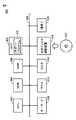
図1は、本実施の形態に係る制御システム1のシステム構成を示す模式図である。図1を参照して、制御システム1は、PLC100と、PLC100に接続されるサポート装置300と、PLC100からのアクセスを受けるデータベース装置400とを含む。PLC100は、後述するようなユーザプログラムを周期的またはイベント的に実行する。ユーザプログラムは、PLC100の利用者によって作成される。ユーザは、例えばサポート装置300を操作することにより、アクセス命令を含むプログラム(ソースプログラム)を作成することができる。サポート装置300は、ソースプログラムを、PLC100において実行可能な形式に変換し、変換されたユーザプログラムをPLC100へ送信する。PLC100は、ユーザプログラムを実行し、ユーザプログラムに含まれるアクセス命令に従って、データベース装置400にアクセスすることができる。 FIG. 1 is a schematic diagram showing a system configuration of a
すなわち、PLC100およびデータベース装置400は、イーサネット(登録商標)などのネットワーク112を介して、データを互いに遣り取りできるように構成される。 That is, the
サポート装置300は、PLC100に接続可能な情報処理装置の典型例である。サポート装置300は、接続ケーブル114を介してPLC100に接続され、PLC100との間で各種パラメータの設定、プログラミング、モニタ、デバッグなどの機能を提供する。PLC100とサポート装置300との間は、典型的には、USB(Universal Serial Bus)規格に従って通信可能に構成される。 The
PLC100は、制御演算を実行するCPUユニット104と、1つ以上のIO(Input/Output)ユニット106とを含む。これらのユニットは、PLCシステムバス108を介して、データを互いに遣り取りできるように構成される。また、これらのユニットには、電源ユニット102によって適切な電圧の電源が供給される。 The
制御システム1において、PLC100は、(PLCシステムバス108を介して接続される)IOユニット106を介して、および/または、フィールドバス110を介して、各種のフィールド機器との間でデータを遣り取りする。これらのフィールド機器は、制御対象に対して何らかの処理を行うためのアクチュエータや、制御対象から各種情報を取得するためのセンサなどを含む。図1には、このようなフィールド機器の一例として、検出スイッチ10、リレー20およびモータ32を駆動するサーボモータドライバ30を含む。また、PLC100は、フィールドバス110を介してリモートIOターミナル200も接続されている。リモートIOターミナル200は、基本的には、IOユニット106と同様に、一般的な入出力処理に関する処理を行う。より具体的には、リモートIOターミナル200は、フィールドバス110でのデータ伝送に係る処理を行うための通信カプラ202と、1つ以上のIOユニット204とを含む。これらのユニットは、リモートIOターミナルバス208を介して、データを互いに遣り取りできるように構成される。 In the
<B.PLC100の構成>
次に、本実施の形態に係るPLC100の構成について説明する。図2は、本実施の形態に係るPLC100の主要部を示すハードウェア構成を示す模式図である。図3は、本実施の形態に係るPLC100のソフトウェア構成を示す模式図である。<B. Configuration of
Next, the configuration of
図2を参照して、PLC100のCPUユニット104のハードウェア構成について説明する。CPUユニット104は、プロセッサ120と、チップセット122と、システムクロック124と、主メモリ126と、不揮発性メモリ128と、USBコネクタ130と、PLCシステムバスコントローラ140と、フィールドバスコントローラ150と、上位通信コントローラ160と、メモリカードインターフェイス170とを含む。チップセット122と他のコンポーネントとの間は、各種のバスを介してそれぞれ結合されている。 The hardware configuration of the
プロセッサ120およびチップセット122は、典型的には、汎用的なコンピュータアーキテクチャに準じて構成される。すなわち、プロセッサ120は、チップセット122から内部クロックに従って順次供給される命令コードを解釈して実行する。チップセット122は、接続されている各種コンポーネントとの間で内部的なデータを遣り取りするとともに、プロセッサ120に必要な命令コードを生成する。システムクロック124は、予め定められた周期のシステムクロックを発生してプロセッサ120に提供する。チップセット122は、プロセッサ120での演算処理の実行の結果得られたデータなどをキャッシュする機能を有する。また、チップセット122は、システムクロック124から提供されるクロックを受けて時刻を計時する計時チップ123を含む。 The
CPUユニット104は、記憶手段として、主メモリ126および不揮発性メモリ128を有する。主メモリ126は、揮発性の記憶領域であり、プロセッサ120で実行されるべき各種プログラムを保持するとともに、各種プログラムの実行時の作業用メモリとしても使用される。不揮発性メモリ128は、OS(Operating System)、システムプログラム、ユーザプログラム、ログ情報などを不揮発的に保持する。 The
USBコネクタ130は、サポート装置300とCPUユニット104とを接続するためのインタフェースである。典型的には、サポート装置300から転送される実行可能なプログラムなどは、USBコネクタ130を介してCPUユニット104に取込まれる。 The
CPUユニット104は、通信手段として、PLCシステムバスコントローラ140、フィールドバスコントローラ150、および上位通信コントローラ160を有する。これらの通信回路は、データの送信および受信を行う。 The
PLCシステムバスコントローラ140は、PLCシステムバス108を介したデータの遣り取りを制御する。より具体的には、PLCシステムバスコントローラ140は、バッファメモリ142と、PLCシステムバス制御回路144と、DMA(Dynamic Memory Access)制御回路146とを含む。PLCシステムバスコントローラ140は、PLCシステムバスコネクタ148を介してPLCシステムバス108と接続される。 The PLC
フィールドバスコントローラ150は、バッファメモリ152と、フィールドバス制御回路154と、DMA制御回路156とを含む。フィールドバスコントローラ150は、フィールドバスコネクタ158を介してフィールドバス110と接続される。上位通信コントローラ160は、バッファメモリ162と、上位通信制御回路164と、DMA制御回路166とを含む。上位通信コントローラ160は、上位通信コネクタ168を介してネットワーク112と接続される。
メモリカードインターフェイス170は、CPUユニット104に対して着脱可能なメモリカード172とプロセッサ120とを接続する。 The
次に、図3を参照して、本実施の形態に係るPLC100が提供する各種機能を実現するためのソフトウェア構成について説明する。これらのソフトウェアに含まれる命令コードは、適切なタイミングで読み出され、CPUユニット104のプロセッサ120によって実行される。 Next, a software configuration for realizing various functions provided by the
図3を参照して、CPUユニット104で実行されるソフトウェアとしては、OS180と、システムプログラム188と、ユーザプログラム186とがある。 Referring to FIG. 3, software executed by
OS180は、プロセッサ120がシステムプログラム188およびユーザプログラム186を実行するための基本的な実行環境を提供する。 The
システムプログラム188は、PLC100としての基本的な機能を提供するためのソフトウェア群である。具体的には、システムプログラム188は、シーケンス命令プログラム190と、DB(データベース)アクセス処理プログラム192と、入出力処理プログラム194と、Toolインタフェース処理プログラム196と、スケジューラ198とを含む。 The
これに対して、ユーザプログラム186は、制御対象に対する制御目的に応じて任意に作成されたプログラムである。すなわち、ユーザプログラム186は、制御システム1を用いて制御する対象に応じて、任意に設計される。 On the other hand, the
ユーザプログラム186は、シーケンス命令プログラム190と協働して、ユーザにおける制御目的を実現する。すなわち、ユーザプログラム186は、シーケンス命令プログラム190によって提供される命令、関数、機能モジュールなどを利用することで、プログラムされた動作を実現する。そのため、ユーザプログラム186およびシーケンス命令プログラム190を「制御プログラム」と総称する場合もある。 The
稼働ログ184には、システムプログラム188およびユーザプログラム186の実行に伴って、予め定められた事象が発生した際に、当該発生した事象の情報が時刻情報と関連付けて格納される。すなわち、稼働ログ184には、システムプログラム188および/またはユーザプログラム186の実行に伴う各種情報がログ(履歴情報)として格納される。 In the
以下、各プログラムについてより詳細に説明する。
シーケンス命令プログラム190は、ユーザプログラム186の実行に伴って、ユーザプログラム186内で指定されているシーケンス命令の実体を呼び出して、その命令の内容を実現するための命令コード群を含む。Hereinafter, each program will be described in more detail.
The
DBアクセス処理プログラム192は、ユーザプログラム186の実行に伴って、データベース装置400へアクセスするために必要な処理を実現するための命令コード群を含む。DBアクセス処理プログラム192は、ユーザプログラム186において指定可能な命令に対応する実行コードを含む。 The DB
入出力処理プログラム194は、IOユニット106や各種のフィールド機器との間で、入力データの取得および出力データの送信を管理するためのプログラムである。 The input /
Toolインタフェース処理プログラム196は、サポート装置300との間でデータを遣り取りするためのインタフェースを提供する。 The Tool interface processing program 196 provides an interface for exchanging data with the
スケジューラ198は、予め定められた優先度やシステムタイマの値などに従って、制御プログラムを実行するためのスレッドやプロシージャを生成する。 The scheduler 198 generates a thread or procedure for executing the control program according to a predetermined priority, a system timer value, or the like.
ユーザプログラム186は、上述したように、ユーザにおける制御目的に応じて作成される。ユーザプログラム186は、典型的には、CPUユニット104のプロセッサ120で実行可能なオブジェクトプログラム形式になっている。ユーザプログラム186は、サポート装置300などにおいて、ラダー形式やファンクションブロック形式で記述されたソースプログラムがコンパイルされることで生成される。そして、生成されたオブジェクトプログラム形式のユーザプログラムは、サポート装置300からCPUユニット104へ転送され、不揮発性メモリ128などに格納される。 As described above, the
PLC100は、図2および図3を用いて説明した構成を備えており、プロセッサ120がシステムプログラム188およびユーザプログラム186を実行することにより、「制御対象を制御するためのユーザプログラムを実行する命令実行部」として機能する。また、PLC100は、プロセッサ120がDBアクセス処理プログラム192およびユーザプログラム186を実行することにより、「データベース装置400へアクセスするためのアクセス命令を含むユーザプログラムの命令実行部による実行時に、アクセス命令に応じた命令文によるデータベース装置400への通信インタフェースを介したアクセスを制御するアクセス処理部」として機能する。PLC100は、DBアクセス処理プログラム192を実行することで、後述する処理によりDB接続サービスの動作モードを第1のモード(稼働モード)または第2のモード(テストモード)のいずれかにより動作させる。PLC100は、プロセッサ120が、ユーザプログラム186に含まれるアクセス命令に応じてDBアクセス処理プログラム192を実行することにより、「第1のモードにおいて、アクセス命令に応じた命令文(SQL文)をデータベース装置400へ送信し、その命令文の応答結果をユーザプログラム186へ応答し、第2のモードにおいて、データベース装置400への命令文を送信することなく命令文に対応する実行結果をユーザプログラム186へ応答する」機能を発揮する。 The
<C.サポート装置300の構成>
次に、本実施の形態に係るサポート装置300について説明する。サポート装置300は、PLC100のCPUユニット104の使用を支援するためのものであり、PLC100との間で各種パラメータの設定、プログラミング、モニタ、デバッグなどの機能を提供する。<C. Configuration of
Next, the
図4は、本実施の形態に係るPLC100に接続して用いられるサポート装置300のハードウェア構成を示す模式図である。サポート装置300は、典型的には、汎用のコンピュータで構成される。 FIG. 4 is a schematic diagram showing a hardware configuration of
図4を参照して、サポート装置300は、OSを含む各種プログラムを実行するCPU302と、BIOSや各種データを格納するROM(Read Only Memory)304と、CPU302でのプログラムの実行に必要なデータを格納するための作業領域を提供するメモリRAM306と、CPU302で実行されるプログラムなどを不揮発的に格納するハードディスク(HDD)308とを含む。より具体的には、ハードディスク308には、サポート装置300が提供する機能を実現するためのサポートプログラム330が格納されている。 Referring to FIG. 4, the
サポート装置300は、さらに、ユーザからの操作を受け付けるキーボード310およびマウス312と、情報をユーザに提示するためのモニタ314とを含む。さらに、サポート装置300は、PLC100(CPUユニット104)などと通信するための通信インタフェース(IF)318を含む。 The
サポート装置300で実行されるサポートプログラム330などは、光学記録媒体332に格納されて流通する。光学記録媒体332に格納されたプログラムは、光学ディスク読取装置316によって読み取られ、ハードディスク308などへ格納される。あるいは、上位のホストコンピュータなどからネットワークを通じてプログラムをダウンロードするように構成してもよい。 The
サポート装置300は、通信IF318によってPLC100と接続する。サポート装置300は、CPU302がサポートプログラム330を実行することで、「DBアクセス処理プログラム192によるユーザプログラム186への応答結果をPLC100から受信する受信処理部」と、「受信処理部により受信した上記の応答結果をモニタ314に表示させる表示処理部」としての機能を発揮する。 The
<D.データベース装置400の構成>
次に、本実施の形態に係るデータベース装置400について説明する。データベース装置400としては、データベースを提供する公知の構成を採用することができる。このようなデータベースとしては、リレーショナルデータ型やオブジェクトデータ型といった任意の構成を採用できる。データベース装置400は、汎用的なコンピュータアーキテクチャに従って構成されるため、ここではその詳細な説明は繰り返さない。<D. Configuration of
Next, the
データベース装置400は、PLC100からの接続要求やアクセス要求(リレーショナルデータ型では、SQL文)を受けて、必要な処理を実行し、その処理結果などをPLC100へ応答する。 The
<E.DB(データベース)へのアクセス処理およびロギングの概要>
次に、本実施の形態に係る制御システム1において、PLC100がデータベース装置400へアクセスする処理の概要を説明する。図5は、本実施形態におけるPLC100とデータベース装置400との通信処理の概要およびロギングの概要を示す図である。<E. Overview of DB (database) access processing and logging>
Next, an outline of processing in which the
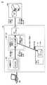
本実施形態のPLC100のCPUユニット104は、DB接続サービスによってデータベース装置400へのアクセス処理を行う。DB接続サービスは、複数の動作モードを切り替えて動作する。本実施形態では、DB接続サービスは、動作モードとして稼働モード(第1のモード)とテストモード(第2のモード)とを切り替えて動作する。 The
稼働モードとは、PLC100を、データベース装置400などの他のシステムと接続した状態で制御システム1を運転させる場合や試運転させる場合に使用する動作モードである。テストモードとは、PLC100を、他のシステムと接続しない状態で、他のシステムに接続するための命令(本実施形態では、DB接続命令)を使用したユーザプログラム186の動作確認時に使用する動作モードである。本実施形態では、DB接続サービスは、テストモードで動作する場合に、データベース装置400へのSQL文の送信を実行せずDB接続サービスを正常終了する。図5では、CPUユニット104のDB接続サービスが稼働モードによって動作する場合を示す。 The operation mode is an operation mode used when the
ユーザプログラム186に、データベース装置400へアクセスするための命令(例えば、図5のDB接続命令「DB_Insert」)が指定されているとする。CPUユニット104は、DB接続サービスを稼働モードで動作させる場合、DB接続命令の実行タイミングになると、DBアクセス処理プログラム192(図3)の対応する命令コードを呼び出して、データベース装置400への接続要求を含むSQL文を生成し、生成したSQL文をデータベース装置400へ送信する。DBアクセス処理プログラム192によって、DB接続サービスが実現されている。ユーザプログラム186内のDB接続命令が実行されることによって、DB接続サービスがトリガーされる。DB接続サービスは、SQL文を生成し、生成したSQL文をDBアクセス機能へ渡す。DBアクセス機能は、各種のデータベースシステムにアクセスするために用意されているドライバソフトウェアである。DBアクセス機能は、上位通信コントローラ160(図2)およびDBアクセス処理プログラム192(図3)によって実現される機能であり、DB接続サービスから受け取ったSQL文を、ネットワーク112を経由してデータベース装置400へ送信する。 It is assumed that a command for accessing the database apparatus 400 (for example, a DB connection command “DB_Insert” in FIG. 5) is specified in the
データベース装置400は、PLC100からのSQL文を受信すると、受信したSQL文に従って処理を実行し、必要に応じて、その結果をPLC100へ応答する。 Upon receiving the SQL statement from the
また、本実施の形態に係るログ出力機能は、プログラムにより定められた所定の処理の実行に伴って出力されるログ(以下「実行ログ」とも称す。)や、プログラムの実行失敗やハードウェアの不具合の発生に伴って出力されるログ(以下「イベントログ」とも称す。)を出力することが可能になっている。稼働ログ184は、これらのすべてのログを含む。本実施形態では、PLC100は、後述するように、PLC100に装着されるメモリカード等の記録媒体に稼働ログ184を書き込む例を説明する。メモリカード等の記録媒体は、稼働ログ184をログファイルとして格納している。 In addition, the log output function according to the present embodiment is a log (hereinafter also referred to as “execution log”) that is output in accordance with execution of a predetermined process determined by the program, a program execution failure, a hardware It is possible to output a log (hereinafter also referred to as “event log”) that is output when a problem occurs. The
実行ログは、予め定められた種類の処理が実行された際に、その処理内容を時刻情報と関連付けて記録した情報である。この実行ログによって、ユーザプログラム186において指定された処理が実行されたことを確認することができる。実行ログは、基本的には、PLC100が稼働中(プログラムによって予め定められた種類の処理を実行している状態)であるときに、常にロギングを行う。イベントログは、指定された処理の実行が失敗したような場合に、その処理内容を時刻情報と関連付けて記録した情報である。典型的には、指定された処理がエラーなどで中断したような場合に、その内容がロギングされる。例えば、DB接続サービスは、DB接続命令に応じて生成したSQL文を、時刻情報と対応付けてログとして出力する。 The execution log is information in which processing content is recorded in association with time information when a predetermined type of processing is executed. From this execution log, it can be confirmed that the process specified in the
図5には、ユーザプログラム186においてデータベース装置400への接続命令が定義されている例を示す。図5の例では、ユーザは、サポート装置300で実行されるサポートプログラムによって、データベース装置400への接続命令を含むプログラムを作成している。サポート装置300は、作成されたプログラムを、PLC100で実行可能な形式に変換し、変換されたユーザプログラムを、サポート装置300からPLC100へ送信する。但し、ユーザプログラム186に定義される命令は任意に定義でき、この定義される命令の種類は、本発明の範囲に何ら影響を与えるものではない。 FIG. 5 shows an example in which a connection command to the
DB接続サービスは、このDB接続命令の実行(SQL文の作成および送信)に応答し、当該命令によって指定された情報を時刻情報と関連付けて(つまり、実行ログとして)稼働ログ184(図5に示す例では、メモリカード172に格納されるログファイル1842)に書き込む。つまり、PLC100の稼働状況のログが保存される。このとき、ユーザは、稼働ログ184への実行ログの書き込みを明示的に指示する必要はなく、DB接続命令が実行されると、DB接続サービスが自動的に稼働状況を稼働ログ184へ書き込むようなシステム環境が構築されている。 The DB connection service responds to the execution of this DB connection command (creation and transmission of an SQL statement), associates the information specified by the command with the time information (that is, as an execution log), and the operation log 184 (FIG. 5). In the example shown, the log file 1842) stored in the
なお、稼働ログ184の書き込み先は、メモリカード172に限らず、主メモリ126や不揮発性メモリ128(図2)であってもよいし、あるいは、PLC100の外部にある記憶装置であってもよい。但し、PLC100の電源が遮断された場合であっても、これらの稼働ログ184を保持できる記憶装置が好ましい。 The write destination of the
図6は、本実施形態におけるPLC100がテストモードで動作する場合の通信処理の概要およびロギングの概要を示す図である。DB接続サービスをテストモードまたは稼働モードのいずれで動作させるかは、サポート装置300から指示を与えることができる。 FIG. 6 is a diagram illustrating an overview of communication processing and an overview of logging when the
テストモードでの動作について、DB接続サービスが稼働モードで動作する場合と比較する。DB接続サービスは、テストモードでの動作時に、DB接続命令に応じてSQL文を生成し、生成したSQL文をデータベース装置400へ送信することなくSQL文の実行結果をユーザプログラム186へ応答する。DB接続サービスは、SQL文の実行がデータベース装置400において正常に行われたことを示す応答と、SQL文の実行がデータベース装置400においてエラーとなったことを示す応答のいずれかをユーザプログラム186へ出力する(いずれの応答を出力するかは設定可能となっている)。例えば、サポート装置300を用いてユーザプログラム186のデバッグを行う場合に、CPUユニット104のDB接続サービスをテストモードで動作させ、データベース装置400において処理が正常に行われたことを示す応答と、データベース装置400における処理にエラーが発生したことを示す応答とのそれぞれについてユーザプログラム186の動作の確認を行いたい場合などがある。 The operation in the test mode will be compared with the case where the DB connection service operates in the operation mode. The DB connection service generates an SQL statement in response to the DB connection command when operating in the test mode, and responds to the execution result of the SQL statement to the
DB接続サービスは、テストモードで動作する場合も、DB接続命令に応じて生成するSQL文を稼働ログ184へ書き込む。これにより、ユーザプログラム186のデバッグを容易にする。 Even when the DB connection service operates in the test mode, the SQL statement generated according to the DB connection command is written to the
また、サポート装置300は、テストモードにおけるDB接続サービスの応答時間を設定することができる。上記のように、DB接続サービスは、テストモードで動作する場合はSQL文をデータベース装置400へ送信することなくユーザプログラム186へ応答する。ここで、ユーザは、サポート装置300を操作することでDB接続サービスの応答時間を設定し、ユーザプログラム186に含まれるDB接続命令によってDB接続サービスを呼び出した後、設定した応答時間が経過してからDB接続サービスに応答結果を出力させるようにすることができる。これにより、想定されるデータベース装置400からの応答時間を考慮して、DB接続サービスをテストモードにしてユーザプログラム186のデバッグを行うことができる。 Further, the
<F.稼働ログ184>
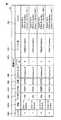
図7を参照して、PLC100が記録する稼働ログ184について説明する。図7は、稼働ログ184を示す図である。稼働ログ184に記録されるログは、エントリ184Aと、日時184Bと、カテゴリ184Cと、ログ名184Dと、結果184Eと、コネクション名184Fと、シリアルID184Gと、テーブル名184Hと、SQL文184Jとを含む。<F. Operation log 184>
The
日時184Bは、ログの取得対象となる処理が発生した時刻を示す。カテゴリ184Cは、ログの属性を示す。ログ名184Dは、ログの内容を一見して把握できる情報を含む。結果184Eは、処理の結果を示すコードが含まれ、例えばデータベース装置400との接続が成功したか失敗したかを示す情報が含まれる。DBコネクション名184FおよびシリアルID184Gは、主として、DB接続に関する情報であり、予め設定されている接続の設定のうち、いずれの設定が使用されたかといった情報を含む。184Hは、PLC100が接続したデータベーステーブルを識別する情報を含む。SQL文184Jは、DB接続サービスがDB接続命令に応じて生成したSQL文を示す。 The date / time 184B indicates the time at which the processing to be acquired of the log occurs. The category 184C indicates log attributes. The log name 184D includes information that allows the user to grasp the contents of the log at a glance. The
<G.処理手順>
次に、本実施の形態にかかるPLC100とデータベース装置400との通信処理およびロギングの処理について説明する。図8は、本実施の形態にかかるPLC100における処理手順およびデータベース装置400の処理手順を示すフローチャートである。図8において、DB接続サービス(DBアクセス処理プログラム)は、稼働モードにより動作している。<G. Processing procedure>
Next, communication processing and logging processing between the
図8に示す各ステップは、CPUユニット104のプロセッサ120がユーザプログラム186およびシステムプログラム188をそれぞれ実行することで実現される。なお、図8には、ユーザプログラム186およびシステムプログラム188が互いに独立して実行される例を示すが、両プログラムを包含する単一のプログラムを実行するようにしてもよい。 Each step shown in FIG. 8 is realized by the
図8を参照して、ユーザプログラム186の実行に関して、プロセッサ120は、予め格納されているユーザプログラム186をロードし、ロードしたユーザプログラム186を予め定められた周期で繰り返し実行する。なお、このロードされるユーザプログラム186は、コンパイルされて実行可能なオブジェクト形式になっているものとする。但し、ユーザによって作成されたソースコードのままロードする、あるいは、ソースコードを中間コードにコンパイルしたものをロードするようにしてもよい。この場合には、ロードされたコードを逐次コンパイルしつつ、プロセッサ120は、処理を実行することになる。すなわち、プロセッサ120は、ユーザプログラム186に含まれる命令に従って、必要に応じてシステムプログラム188を呼び出しつつ、指定された処理を実行する。 Referring to FIG. 8, regarding execution of
ステップS101において、プロセッサ120は、ユーザプログラム186に含まれる命令に従って処理を実行し、データベース装置400へアクセスするための命令を実行すると、DBアクセス処理プログラム192によるデータベース装置400へのアクセス処理を開始する。 In step S <b> 101, the
ステップS201において、プロセッサ120は、DBアクセス処理プログラム192によってデータベース装置400へのアクセスを実行するため、ユーザプログラム186に含まれる、データベース装置400へアクセスするための命令に応じた命令文(SQL文)を生成する。 In step S201, the
ステップS203において、プロセッサ120は、生成したSQL文をデータベース装置400へ送信し、この送信処理に係るログを稼働ログ184に保存する。 In step S <b> 203, the
ステップS205において、プロセッサ120は、データベース装置400との通信のタイムアウト期間を設定するとともに、通信タイムアウトが発生するまでデータベース装置400からの応答を受け付ける。 In step S205, the
ステップS401において、データベース装置400は、PLC100から送信されるSQL文を受信し、受信したSQL文を実行する。 In step S401, the
ステップS403において、データベース装置400は、SQL文の実行結果をPLC100へ応答する。 In step S403, the
ステップS207において、プロセッサ120は、データベース装置400との通信に設定したタイムアウト期間が経過する前にデータベース装置400におけるSQL文の実行結果を示す応答をデータベース装置400から受信すると、データベース装置400からの応答をDBアクセス処理プログラム192からユーザプログラム186へ渡す。また、プロセッサ120は、データベース装置400から受信した応答結果に関するログを稼働ログ184に保存する。 In step S207, when the
ステップS103において、プロセッサ120は、SQL文の実行結果に応じてユーザプログラム186を実行する。 In step S103, the
(テストモードにおけるDB接続サービスの動作)
次に、図9を参照して、テストモードにおけるDB接続サービス(DBアクセス処理プログラム)の動作について説明する。図9は、テストモードにおけるPLC100の処理手順を示すフローチャートである。上述したように、テストモードにおいて、DB接続サービスは、ユーザプログラム186に含まれるDB接続命令によって呼び出され、サポート装置300等によって設定された応答時間の経過後に応答結果を出力するものとする。(Operation of DB connection service in test mode)
Next, the operation of the DB connection service (DB access processing program) in the test mode will be described with reference to FIG. FIG. 9 is a flowchart showing a processing procedure of the
ステップS101において、プロセッサ120は、ユーザプログラム186に含まれる命令に従って処理を実行し、データベース装置400へアクセスするための命令を実行すると、DBアクセス処理プログラム192を動作させる。 In step S <b> 101, the
ステップS201において、プロセッサ120は、DBアクセス処理プログラム192によって、ユーザプログラム186に含まれる、データベース装置400へアクセスするための命令に応じた命令文(SQL文)を生成する。 In step S <b> 201, the
ステップS211において、プロセッサ120は、設定された応答時間が経過するまで待機する。 In step S211, the
ステップS213において、プロセッサ120は、ステップS201で生成したSQL文を稼働ログ184に保存する。 In step S213, the
ステップS215において、プロセッサ120は、生成したSQL文をデータベース装置400へ送信することなく、生成したSQL文に対応する命令実行結果をDBアクセス処理プログラム192からユーザプログラム186へ応答する。 In step S215, the
ステップS103において、プロセッサ120は、SQL文の実行結果に応じてユーザプログラム186を実行する。 In step S103, the
以上の図8および図9に示した処理により、DB接続サービスは、稼働モードとテストモードとを切り替えて動作する。 With the processing shown in FIGS. 8 and 9, the DB connection service operates by switching between the operation mode and the test mode.
<H.ログの取得>
PLC100によって記録される稼働ログ184は、例えば、サポート装置300によって取得され、ユーザは、サポート装置300を操作することによって稼働ログ184を参照することができる。例えば、サポート装置300は、以下のようにして稼働ログ184をPLC100から取得する。すなわち、サポート装置300は、PLC100と通信し、PLC100のシステムプログラム188によって稼働ログ184をメモリから読み出して、読み出された稼働ログ184をPLC100からサポート装置300へ応答させる。<H. Log acquisition>
The
図10は、サポート装置300が稼働ログ184を取得するための処理を示すフローチャートである。 FIG. 10 is a flowchart illustrating a process for the
ステップS311において、サポート装置300は、PLC100に対し、稼働ログ184の取得を指示する。 In step S <b> 311, the
ステップS221において、プロセッサ120は、システムプログラム188を実行することにより、稼働ログの取得の指示に応じて稼働ログ184を取得する。 In step S <b> 221, the
ステップS223において、プロセッサ120は、システムプログラム188の処理により、取得した稼働ログ184をユーザプログラム186へ応答する。 In step S <b> 223, the
ステップS313において、サポート装置300は、PLC100から稼働ログ184を取得し、取得した稼働ログ184をモニタ314に表示する。 In step S313, the
ユーザプログラム186の実行によって稼働ログ184を読み出すことで、例えばユーザプログラム186の任意の命令の実行後に稼働ログ184を取得することができ、ユーザは、PLC100とデータベース装置400との通信における不具合等の原因に対処することができる。 By reading the operation log 184 by executing the
この他にも、ユーザプログラムに所定の命令を含めることによって、稼働ログ184をメモリから読み出すこととしてもよい。ユーザは、サポート装置300を操作して、ユーザプログラム186にログ取得命令を含ませることができる。プロセッサ120は、ユーザプログラム186のログ取得命令により、システムプログラム188またはDBアクセス処理プログラム192を呼び出しつつ稼働ログ184を読み出す処理を実行する。ユーザプログラム186が稼働ログ184を読み出すことで、例えばサポート装置300において稼働ログ184を表示することができる。 In addition, the operation log 184 may be read from the memory by including a predetermined command in the user program. The user can operate the
<I.サポート装置300による動作モードの指示の例>
CPUユニット104のDB接続サービスを稼働モードとテストモードのいずれの動作モードで動作させるかを切り替える処理は、例えば、サポート装置300の指示に基づきPLC100のシステムプログラム188が行うこととしてもよい。<I. Example of operation mode instruction by
For example, the
図11は、サポート装置300がテストモードでの動作指示をPLC100に与える処理手順の例を示す図である。 FIG. 11 is a diagram illustrating an example of a processing procedure in which the
ステップS301において、サポート装置300は、CPUユニット104のDB接続サービスをテストモードで動作させるための入力操作をユーザから受け付ける。 In step S301, the
ステップS303において、サポート装置300は、ステップS301における入力操作に応じて、動作モードを切り替えるための指示をCPUユニット104へ送信する。 In step S303, the
ステップS121において、CPUユニット104のプロセッサ120は、システムプログラム188の機能によってサポート装置300と通信し、サポート装置300から、動作モードを切り替えるための指示を受け付ける。プロセッサ120は、サポート装置300から受け付けた指示に従って、DB接続サービスの動作モードを設定する。 In step S <b> 121, the
ステップS123において、プロセッサ120は、DB接続サービスの動作モードの設定変更が完了すると、設定が完了したことをサポート装置300へ通知する。 In step S123, when the setting change of the operation mode of the DB connection service is completed, the
ステップS305において、サポート装置300は、DB接続サービスの動作モードの設定変更が完了したことをCPUユニット104から受信する。 In step S305, the
このようにして、サポート装置300は、ユーザの入力操作に応じてPLC100のDB接続サービスの動作モードを切り替えることができ、ユーザによるデバッグを容易にすることができる。 In this way, the
この他にも、ユーザプログラムに、DB接続サービスを稼働モードとテストモードのいずれで動作させるかを指定する命令を含めることができることとしてもよい。ユーザは、サポート装置300を用いたプログラムの作成時に、DB接続サービスを稼働モードとテストモードのいずれで動作させるかを定義する。サポート装置300によって、動作モードの指定を含むユーザプログラムが生成され、PLC100へ送信されると、PLC100は、ユーザプログラムの実行時に、動作モードの指定に従って動作する。 In addition, the user program may include an instruction for designating whether the DB connection service is operated in the operation mode or the test mode. When creating a program using the
<J.ユーザインタフェースの例>
図12は、本実施形態にかかるサポート装置300において提供されるユーザインタフェースの一例を示す図である。サポート装置300は、稼働ログ184をサポート装置300のモニタに表示させることができる。<J. User interface example>
FIG. 12 is a diagram illustrating an example of a user interface provided in the
サポート装置300は、例えば、上記の図10で示した手順により、稼働ログ184をPLC100から取得する。 For example, the
図12に示すように、表示画面380は、稼働ログ184を一覧にして表示する。稼働ログ表示部388の各エントリ(エントリ381、エントリ382、エントリ383、エントリ384)は、稼働ログ184(図7に示す)に含まれる各種のデータを表示する。 As shown in FIG. 12, the
サポート装置300は、例えば取得ボタン390を表示画面380に含めて表示し、ユーザから取得ボタン390に対する入力操作を受け付けることにより、PLC100から稼働ログ184を取得することとしてもよい。例えば、取得ボタン390に対する入力操作を受け付けることにより、上記の図10で示した手順をサポート装置300に実行させることとしてもよい。また、ユーザが選択しているエントリ(図12では、エントリ381を枠で強調して示すことにより、エントリ381がユーザによって選択されていることを示す)について、詳細な情報を稼働ログ表示部388に表示することとしてもよい。例えば、図12の例では、エントリ381において、DB接続サービスが生成したSQL文のログを詳細情報389に表示している。 For example, the
上述したような構成を採用することで、ユーザは、PLCを他のシステム(データベースシステムなど)と接続する構成とする場合に、実際の他のシステムとPLCとを通信させずとも、PLCのDB接続サービスをテストモードで動作させることにより、PLCと他のシステムとを協働させて動作するユーザプログラムのデバッグを容易にしている。 By adopting the configuration as described above, when the user configures the PLC to connect to another system (such as a database system), the PLC DB can be used without communicating the actual other system with the PLC. By operating the connection service in the test mode, debugging of a user program that operates in cooperation with the PLC and another system is facilitated.
また、上記の実施形態の説明では、サポート装置300が稼働ログ184をモニタに表示するため、例えばPLC100がサポート装置300から稼働ログ184の読み出し要求をシステムプログラム188によって受け付けた場合に、稼働ログ184を所定のメモリから読み出してサポート装置300へ応答する例を説明した。この他にも、例えばCPUユニット104がFTP(File Transfer Protocol)サーバ機能を備え、FTPクライアントソフトによってCPUユニット104にログインし、FTPクライアントソフトが稼働ログ184をFTPによって取得することとしてもよい。 In the description of the above embodiment, since the
今回開示された実施の形態はすべての点で例示であって制限的なものではないと考えられるべきである。本発明の範囲は、上記した説明ではなく、特許請求の範囲によって示され、特許請求の範囲と均等の意味および範囲内でのすべての変更が含まれることが意図される。 The embodiment disclosed this time should be considered as illustrative in all points and not restrictive. The scope of the present invention is defined by the terms of the claims, rather than the description above, and is intended to include any modifications within the scope and meaning equivalent to the terms of the claims.
1 制御システム、10 検出スイッチ、20 リレー、30 サーボモータドライバ、32 モータ、100 PLC、102 電源ユニット、104 CPUユニット、106 IOユニット、108 PLCシステムバス、110 フィールドバス、112 ネットワーク、114 接続ケーブル、120 プロセッサ、122 チップセット、124 システムクロック、126 主メモリ、128 不揮発性メモリ、130 USBコネクタ、140 PLCシステムバスコントローラ、142,152,162 バッファメモリ、144 PLCシステムバス制御回路、146,156,166 DMA制御回路、148 PLCシステムバスコネクタ、150 フィールドバスコントローラ、154 フィールドバス制御回路、158 フィールドバスコネクタ、160 上位通信コントローラ、164 上位通信制御回路、168 上位通信コネクタ、170 メモリカードインターフェイス、172 メモリカード、180 OS、184 稼働ログ、184J SQL文、1842 ログファイル、186 ユーザプログラム、188 システムプログラム、190 シーケンス命令プログラム、192 アクセス処理プログラム、194 入出力処理プログラム、196 インタフェース処理プログラム、198 スケジューラ、200 リモートIOターミナル、202 通信カプラ、208 ターミナルバス、300 サポート装置、302 CPU、304 ROM、306 RAM、308 ハードディスク、310 キーボード、312 マウス、314 モニタ、316 光学ディスク読取装置、330 サポートプログラム、332 光学記録媒体、388 稼働ログ表示部、389 詳細情報表示部、400 データベース装置。 1 control system, 10 detection switch, 20 relay, 30 servo motor driver, 32 motor, 100 PLC, 102 power supply unit, 104 CPU unit, 106 IO unit, 108 PLC system bus, 110 field bus, 112 network, 114 connection cable, 120 processor, 122 chipset, 124 system clock, 126 main memory, 128 non-volatile memory, 130 USB connector, 140 PLC system bus controller, 142, 152, 162 buffer memory, 144 PLC system bus control circuit, 146, 156, 166 DMA control circuit, 148 PLC system bus connector, 150 field bus controller, 154 field bus control circuit, 158 feel Bus connector, 160 host communication controller, 164 host communication control circuit, 168 host communication connector, 170 memory card interface, 172 memory card, 180 OS, 184 operation log, 184J SQL statement, 1842 log file, 186 user program, 188 system program 190 sequence instruction program, 192 access processing program, 194 input / output processing program, 196 interface processing program, 198 scheduler, 200 remote IO terminal, 202 communication coupler, 208 terminal bus, 300 support device, 302 CPU, 304 ROM, 306 RAM 308 Hard disk 310 Keyboard 312 Mouse 314 Monitor 316 Optical disk Reading device, 330 support program, 332 optical recording medium, 388 operation log display unit, 389 detailed information display unit, 400 database device.
Claims (11)
Translated fromJapaneseデータベースシステムと接続するための通信インタフェースと、
制御対象を制御するためのユーザプログラムを実行する命令実行部と、
前記データベースシステムへアクセスするためのアクセス命令を含む前記ユーザプログラムの前記命令実行部による実行時に、前記アクセス命令に応じた命令文による前記データベースシステムへの前記通信インタフェースを介したアクセスを制御するアクセス処理部とを備え、
前記アクセス処理部は、第1のモードと第2のモードとにより動作可能であり、
前記第1のモードにおいて、前記アクセス命令に応じた命令文を前記データベースシステムへ送信し、その命令文の応答結果を前記ユーザプログラムへ応答し、
前記第2のモードにおいて、前記データベースシステムへの前記命令文を送信することなく前記命令文に対応する実行結果を前記ユーザプログラムへ応答する、コントローラ。A controller,
A communication interface for connecting to the database system;
An instruction execution unit for executing a user program for controlling a control target;
Access processing for controlling access to the database system via the communication interface by a command statement corresponding to the access command when the command execution unit of the user program including an access command for accessing the database system is executed With
The access processing unit is operable in a first mode and a second mode,
In the first mode, a command statement corresponding to the access command is transmitted to the database system, a response result of the command statement is returned to the user program,
In the second mode, the controller responds to the user program with an execution result corresponding to the command statement without transmitting the command statement to the database system.
時刻を計時する計時部をさらに備え、
前記命令実行部は、前記ユーザプログラムの所定の処理の実行時に、処理内容と前記計時部が計時する時刻とを対応付けてログとしてメモリに保存し、
前記アクセス処理部は、前記アクセス命令に応じた処理内容と前記計時部が計時する時刻とを対応付けて前記ログとして前記メモリに保存する、請求項1記載のコントローラ。The controller is
It further includes a timekeeping part that keeps time
The instruction execution unit stores a processing content and a time counted by the timing unit in a memory in a memory in association with a time measured by the user program when the predetermined process is executed.
2. The controller according to claim 1, wherein the access processing unit associates the processing content according to the access command with the time measured by the time measuring unit and stores it in the memory as the log.
前記アクセス命令に応じた命令文を生成し、生成した命令文を前記ログとして前記メモリに保存する、請求項2に記載のコントローラ。The access processing unit
The controller according to claim 2, wherein a command statement corresponding to the access command is generated, and the generated command statement is stored in the memory as the log.
前記第2のモードにおいて、前記アクセス命令に応じた前記命令文に対応する実行結果として、前記命令文による前記データベースシステムへのアクセスが正常になされたことを示す応答、または、前記命令文による前記データベースシステムへのアクセスにエラーが発生したことを示す応答を前記ユーザプログラムへ行う、請求項1に記載のコントローラ。The access processing unit
In the second mode, as an execution result corresponding to the command statement according to the access command, a response indicating that the database has been normally accessed by the command statement, or the command statement The controller according to claim 1, wherein a response indicating that an error has occurred in accessing the database system is sent to the user program.
応答時間の設定を受け付ける応答時間設定部を含み、
前記第2のモードで動作する場合に、前記アクセス命令に応じた処理の結果を、前記処理の開始から前記設定された応答時間の経過後に出力する、請求項1に記載のコントローラ。The controller is
Including a response time setting unit that accepts response time settings;
2. The controller according to claim 1, wherein when operating in the second mode, a result of a process corresponding to the access command is output after the set response time has elapsed from the start of the process.
前記入出力部は、前記情報処理装置の要求に応じて、前記アクセス処理部による前記ユーザプログラムへの応答結果を前記情報処理装置へ出力する、請求項1から5のいずれか1項に記載のコントローラ。The controller includes an input / output unit for transmitting and receiving data to and from an information processing apparatus connected to the controller.
6. The input / output unit according to claim 1, wherein the input / output unit outputs a response result to the user program by the access processing unit to the information processing device in response to a request from the information processing device. controller.
前記アクセス処理部は、前記情報処理装置から受け付けた指定に応じて前記第1のモードと前記第2のモードとを切り替える、請求項6記載のコントローラ。The input / output unit receives from the information processing apparatus a designation as to whether the access processing unit is operated in the first mode or the second mode,
The controller according to claim 6, wherein the access processing unit switches between the first mode and the second mode in accordance with a designation received from the information processing apparatus.
前記アクセス処理部は、
前記指定命令に示される指定に従って、前記第1のモードと前記第2のモードとのいずれかで動作する、請求項1記載のコントローラ。The user program includes a designation command that designates whether the access processing unit is operated in the first mode or the second mode,
The access processing unit
The controller according to claim 1, wherein the controller operates in one of the first mode and the second mode in accordance with a designation indicated by the designation instruction.
前記コントローラは、データベースシステムへアクセスするための通信インタフェースと、プロセッサと、メモリとを備え、
前記プログラムは、前記プロセッサに、
制御対象を制御するためのユーザプログラムを実行するステップと、
前記データベースシステムへアクセスするためのアクセス命令を含む前記ユーザプログラムの前記実行時に、前記アクセス命令に応じた命令文による前記データベースシステムへの前記通信インタフェースを介したアクセスを制御するステップとを実行させ、
前記アクセス命令に応じた命令文によるデータベースシステムへのアクセスを制御するステップは、第1のモードと第2のモードとにより動作可能であり、前記プロセッサに、
前記第1のモードにおいて、前記アクセス命令に応じた命令文を前記データベースシステムへ送信し、その命令文の応答結果を前記ユーザプログラムへ応答し、
前記第2のモードにおいて、前記データベースシステムへの前記命令文を送信することなく前記命令文に対応する実行結果を前記ユーザプログラムへ応答するステップを実行させる、プログラム。A program for controlling the operation of the controller,
The controller includes a communication interface for accessing the database system, a processor, and a memory,
The program is stored in the processor.
Executing a user program for controlling the controlled object;
Controlling the access through the communication interface to the database system by a command statement according to the access command when executing the user program including an access command for accessing the database system;
The step of controlling access to the database system by a statement according to the access instruction is operable in a first mode and a second mode, and the processor
In the first mode, a command statement corresponding to the access command is transmitted to the database system, a response result of the command statement is returned to the user program,
In the second mode, a program for executing a step of responding to the user program with an execution result corresponding to the command statement without transmitting the command statement to the database system.
前記コントローラは、
データベースシステムと接続するための通信インタフェースと、
制御対象を制御するためのユーザプログラムを実行する命令実行部と、
前記データベースシステムへアクセスするためのアクセス命令を含む前記ユーザプログラムの前記命令実行部による実行時に、前記アクセス命令に応じた命令文による前記データベースシステムへの前記通信インタフェースを介したアクセスを制御するアクセス処理部と、
前記情報処理装置と接続し、前記情報処理装置とデータを送受信するための入出力部とを備え、
前記アクセス処理部は、第1のモードと第2のモードとにより動作可能であり、
前記第1のモードにおいて、前記アクセス命令に応じた命令文を前記データベースシステムへ送信し、その命令文の応答結果を前記ユーザプログラムへ応答し、
前記第2のモードにおいて、前記データベースシステムへの前記命令文を送信することなく前記命令文に対応する実行結果を前記ユーザプログラムへ応答する、第1のモードと第2のモードとにより動作可能であり、
前記情報処理装置は、
前記アクセス処理部による前記ユーザプログラムへの応答結果を前記コントローラの前記入出力部を介して受信する受信処理部と、
前記受信処理部により受信した前記応答結果をモニタに表示させる表示処理部とを備える、情報処理装置。An information processing apparatus connected to a controller,
The controller is
A communication interface for connecting to the database system;
An instruction execution unit for executing a user program for controlling a control target;
Access processing for controlling access to the database system via the communication interface by a command statement corresponding to the access command when the command execution unit of the user program including an access command for accessing the database system is executed And
An input / output unit for connecting to the information processing apparatus and transmitting / receiving data to / from the information processing apparatus;
The access processing unit is operable in a first mode and a second mode,
In the first mode, a command statement corresponding to the access command is transmitted to the database system, a response result of the command statement is returned to the user program,
In the second mode, it is possible to operate in the first mode and the second mode in which the execution result corresponding to the command statement is responded to the user program without transmitting the command statement to the database system. Yes,
The information processing apparatus includes:
A reception processing unit for receiving a response result to the user program by the access processing unit via the input / output unit of the controller;
An information processing apparatus comprising: a display processing unit that displays the response result received by the reception processing unit on a monitor.
データベースシステムと接続するための通信インタフェースと、
プロセッサと、
メモリとを備え、
前記プロセッサは、第1のモードと第2のモードとを切り替えて動作し、制御対象を制御するためのユーザプログラムを実行し、前記データベースシステムへアクセスするためのアクセス命令を含む前記ユーザプログラムの前記実行時に、前記アクセス命令に応じた命令文による前記データベースシステムへの前記通信インタフェースを介したアクセスを制御し、第1のモードで動作する場合に、前記アクセス命令に応じた命令文を前記データベースシステムへ送信し、その命令文の応答結果を前記ユーザプログラムへ応答し、第2のモードで動作する場合に、前記データベースシステムへの前記命令文を送信することなく前記命令文に対応する実行結果を前記ユーザプログラムへ応答する、コントローラ。A controller,
A communication interface for connecting to the database system;
A processor;
With memory,
The processor operates by switching between a first mode and a second mode, executes a user program for controlling a control target, and includes an access command for accessing the database system. When executing the first mode by controlling access via the communication interface to the database system by a command statement according to the access command at the time of execution, the command statement according to the access command is transmitted to the database system. When the response to the user program is returned to the user program and the operation is performed in the second mode, the execution result corresponding to the command statement is transmitted without transmitting the command statement to the database system. A controller responsive to the user program.
Priority Applications (4)
| Application Number | Priority Date | Filing Date | Title |
|---|---|---|---|
| JP2013028265AJP6171387B2 (en) | 2013-02-15 | 2013-02-15 | Controller, information processing apparatus and program |
| US14/088,481US9984244B2 (en) | 2013-02-15 | 2013-11-25 | Controller, information processing apparatus, and recording medium |
| EP13194398.7AEP2767906A1 (en) | 2013-02-15 | 2013-11-26 | Controller, information processing apparatus, and program |
| CN201310656213.5ACN103995499B (en) | 2013-02-15 | 2013-12-06 | controller, information processing device |
Applications Claiming Priority (1)
| Application Number | Priority Date | Filing Date | Title |
|---|---|---|---|
| JP2013028265AJP6171387B2 (en) | 2013-02-15 | 2013-02-15 | Controller, information processing apparatus and program |
Publications (2)
| Publication Number | Publication Date |
|---|---|
| JP2014157506A JP2014157506A (en) | 2014-08-28 |
| JP6171387B2true JP6171387B2 (en) | 2017-08-02 |
Family
ID=49683509
Family Applications (1)
| Application Number | Title | Priority Date | Filing Date |
|---|---|---|---|
| JP2013028265AActiveJP6171387B2 (en) | 2013-02-15 | 2013-02-15 | Controller, information processing apparatus and program |
Country Status (4)
| Country | Link |
|---|---|
| US (1) | US9984244B2 (en) |
| EP (1) | EP2767906A1 (en) |
| JP (1) | JP6171387B2 (en) |
| CN (1) | CN103995499B (en) |
Families Citing this family (14)
| Publication number | Priority date | Publication date | Assignee | Title |
|---|---|---|---|---|
| WO2015170382A1 (en)* | 2014-05-08 | 2015-11-12 | 三菱電機株式会社 | Engineering tool, program editing device, and program editing system |
| KR101870492B1 (en)* | 2015-06-22 | 2018-06-22 | 엘에스산전 주식회사 | Programmable Logic Controller System |
| JP6426666B2 (en)* | 2016-07-27 | 2018-11-21 | ファナック株式会社 | Programmable controller |
| CN107741901A (en)* | 2016-09-28 | 2018-02-27 | 腾讯科技(深圳)有限公司 | A kind of method of testing and device of linked database sentence |
| WO2018112852A1 (en)* | 2016-12-22 | 2018-06-28 | 深圳配天智能技术研究院有限公司 | Ladderlogic programming language-based numerical control apparatus, numerical control system, and debugging method therefor |
| JP6926539B2 (en)* | 2017-03-10 | 2021-08-25 | オムロン株式会社 | Controls and programs |
| JP6504190B2 (en)* | 2017-03-14 | 2019-04-24 | オムロン株式会社 | Control device and information processing method |
| CN108183833B (en)* | 2017-11-29 | 2021-08-10 | 努比亚技术有限公司 | Response processing method and device and computer readable storage medium |
| JP7294391B2 (en)* | 2018-02-26 | 2023-06-20 | オムロン株式会社 | Controller, control method and program |
| JP7013934B2 (en) | 2018-02-26 | 2022-02-01 | オムロン株式会社 | controller |
| JP7087484B2 (en)* | 2018-03-13 | 2022-06-21 | 富士通株式会社 | Information processing equipment, control programs and information processing methods |
| JP7091986B2 (en)* | 2018-10-05 | 2022-06-28 | オムロン株式会社 | Control systems, control methods, and development support programs |
| JP7044086B2 (en)* | 2019-03-15 | 2022-03-30 | オムロン株式会社 | Control systems, control methods, and control programs |
| JP7331507B2 (en) | 2019-07-08 | 2023-08-23 | オムロン株式会社 | Controller, control system and control method |
Family Cites Families (19)
| Publication number | Priority date | Publication date | Assignee | Title |
|---|---|---|---|---|
| US7106843B1 (en)* | 1994-04-19 | 2006-09-12 | T-Netix, Inc. | Computer-based method and apparatus for controlling, monitoring, recording and reporting telephone access |
| JPH10133914A (en)* | 1996-11-01 | 1998-05-22 | Nippon Steel Corp | Computer system and device input / output simulator |
| JP2002023812A (en)* | 2000-07-05 | 2002-01-25 | Mitsubishi Materials Corp | Automatic control system and automatic control method |
| EP1288757A1 (en)* | 2001-08-07 | 2003-03-05 | Siemens Aktiengesellschaft | Method and process control system for operating a technical installation |
| US7032816B2 (en)* | 2001-12-28 | 2006-04-25 | Kimberly-Clark Worldwide, Inc. | Communication between machines and feed-forward control in event-based product manufacturing |
| US7380213B2 (en)* | 2001-12-28 | 2008-05-27 | Kimberly-Clark Worldwide, Inc. | User interface for reporting event-based production information in product manufacturing |
| JP3548829B2 (en)* | 2002-01-10 | 2004-07-28 | オムロン株式会社 | Unit, PLC and User Program Processing Method |
| JP2004005085A (en)* | 2002-05-31 | 2004-01-08 | Hitachi Ltd | Storage network performance measurement system |
| US20050049999A1 (en) | 2003-08-29 | 2005-03-03 | Immo-Gert Birn | Database access statement tracing |
| US7218974B2 (en)* | 2005-03-29 | 2007-05-15 | Zarpac, Inc. | Industrial process data acquisition and analysis |
| US7721154B1 (en)* | 2006-09-05 | 2010-05-18 | Parasoft Corporation | System and method for software run-time testing |
| KR101110975B1 (en)* | 2007-07-10 | 2012-03-14 | 미쓰비시덴키 가부시키가이샤 | Transmitter apparatus and communication system |
| JP2009104490A (en)* | 2007-10-25 | 2009-05-14 | Fujitsu Ltd | Program testing equipment |
| US7970755B2 (en) | 2008-07-02 | 2011-06-28 | Oracle Int'l. Corp. | Test execution of user SQL in database server code |
| EP2372836B1 (en)* | 2010-03-18 | 2017-05-03 | Alcatel Lucent | Antenna array calibration |
| EP2381366A1 (en)* | 2010-04-20 | 2011-10-26 | Siemens Aktiengesellschaft | Method for estimating testing efforts for software unit testing |
| JP5549556B2 (en) | 2010-11-16 | 2014-07-16 | 富士電機株式会社 | Data collection system, data collection system abnormality factor determination method |
| JP5796311B2 (en)* | 2011-03-15 | 2015-10-21 | オムロン株式会社 | Control device and system program |
| JP2012198636A (en)* | 2011-03-18 | 2012-10-18 | Mitsubishi Electric Corp | Controller |
- 2013
- 2013-02-15JPJP2013028265Apatent/JP6171387B2/enactiveActive
- 2013-11-25USUS14/088,481patent/US9984244B2/enactiveActive
- 2013-11-26EPEP13194398.7Apatent/EP2767906A1/ennot_activeWithdrawn
- 2013-12-06CNCN201310656213.5Apatent/CN103995499B/enactiveActive
Also Published As
| Publication number | Publication date |
|---|---|
| EP2767906A1 (en) | 2014-08-20 |
| CN103995499B (en) | 2017-07-25 |
| JP2014157506A (en) | 2014-08-28 |
| US20140236997A1 (en) | 2014-08-21 |
| CN103995499A (en) | 2014-08-20 |
| US9984244B2 (en) | 2018-05-29 |
Similar Documents
| Publication | Publication Date | Title |
|---|---|---|
| JP6171387B2 (en) | Controller, information processing apparatus and program | |
| JP6171386B2 (en) | Controller, information processing apparatus and program | |
| WO2015136959A1 (en) | Control system, method, program and information processing device | |
| US11181890B2 (en) | Control system, information processing device, and anomaly factor estimation program | |
| JP2015001758A (en) | Information processing device, information processing device control method, and control program | |
| JP6969371B2 (en) | Control system and control unit | |
| JP2016110460A (en) | Programmable controller, method for controlling programmable controller and program | |
| JP6442131B2 (en) | Control system and control device | |
| JPWO2012077704A1 (en) | Debug stub server, debugging method and program | |
| JP2016012173A (en) | Programmable display | |
| JP6362821B2 (en) | Control device, control method and instruction set | |
| JP2009251936A (en) | Automatic testing system for picture program of programmable display unit | |
| JP2014157483A (en) | Controller and information processing device | |
| JP6064749B2 (en) | Controller and program | |
| US12072681B2 (en) | Support device, non-transitory computer-readable recording medium recording support program, and setting method | |
| US11215974B2 (en) | Factory automation (FA) system, controller, and control method | |
| JP7331507B2 (en) | Controller, control system and control method | |
| JP7536217B1 (en) | PROGRAMMABLE CONTROLLER, TERMINAL DEVICE, INFORMATION PROVIDING METHOD AND PROGRAM | |
| JP6948186B2 (en) | Equipment management equipment, equipment management system, and equipment management method | |
| JP2759950B2 (en) | Computer system | |
| JP2025112969A (en) | Display control method, display terminal, disaster prevention system, display terminal control method, communication system, communication method, and program | |
| JP2014099060A (en) | Controller, control system, program, and information processing device | |
| JP2020129321A (en) | Cloud server device | |
| JP2002078030A (en) | Remote monitoring control method | |
| KR20120137114A (en) | Self-administered facilities controller, facilities control system having the same and operating method the system |
Legal Events
| Date | Code | Title | Description |
|---|---|---|---|
| A621 | Written request for application examination | Free format text:JAPANESE INTERMEDIATE CODE: A621 Effective date:20160108 | |
| A977 | Report on retrieval | Free format text:JAPANESE INTERMEDIATE CODE: A971007 Effective date:20161110 | |
| A131 | Notification of reasons for refusal | Free format text:JAPANESE INTERMEDIATE CODE: A131 Effective date:20161122 | |
| TRDD | Decision of grant or rejection written | ||
| A01 | Written decision to grant a patent or to grant a registration (utility model) | Free format text:JAPANESE INTERMEDIATE CODE: A01 Effective date:20170606 | |
| A61 | First payment of annual fees (during grant procedure) | Free format text:JAPANESE INTERMEDIATE CODE: A61 Effective date:20170619 | |
| R150 | Certificate of patent or registration of utility model | Ref document number:6171387 Country of ref document:JP Free format text:JAPANESE INTERMEDIATE CODE: R150 | |
| R250 | Receipt of annual fees | Free format text:JAPANESE INTERMEDIATE CODE: R250 | |
| R250 | Receipt of annual fees | Free format text:JAPANESE INTERMEDIATE CODE: R250 |