JP6167348B2 - Imaging lens - Google Patents
Imaging lensDownload PDFInfo
- Publication number
- JP6167348B2 JP6167348B2JP2013188413AJP2013188413AJP6167348B2JP 6167348 B2JP6167348 B2JP 6167348B2JP 2013188413 AJP2013188413 AJP 2013188413AJP 2013188413 AJP2013188413 AJP 2013188413AJP 6167348 B2JP6167348 B2JP 6167348B2
- Authority
- JP
- Japan
- Prior art keywords
- lens
- refractive power
- imaging lens
- negative refractive
- positive
- Prior art date
- Legal status (The legal status is an assumption and is not a legal conclusion. Google has not performed a legal analysis and makes no representation as to the accuracy of the status listed.)
- Active
Links
Images


Classifications
- G—PHYSICS
- G02—OPTICS
- G02B—OPTICAL ELEMENTS, SYSTEMS OR APPARATUS
- G02B13/00—Optical objectives specially designed for the purposes specified below
- G02B13/001—Miniaturised objectives for electronic devices, e.g. portable telephones, webcams, PDAs, small digital cameras
- G02B13/0015—Miniaturised objectives for electronic devices, e.g. portable telephones, webcams, PDAs, small digital cameras characterised by the lens design
- G02B13/002—Miniaturised objectives for electronic devices, e.g. portable telephones, webcams, PDAs, small digital cameras characterised by the lens design having at least one aspherical surface
- G02B13/0045—Miniaturised objectives for electronic devices, e.g. portable telephones, webcams, PDAs, small digital cameras characterised by the lens design having at least one aspherical surface having five or more lenses
- G—PHYSICS
- G02—OPTICS
- G02B—OPTICAL ELEMENTS, SYSTEMS OR APPARATUS
- G02B27/00—Optical systems or apparatus not provided for by any of the groups G02B1/00 - G02B26/00, G02B30/00
- G02B27/0025—Optical systems or apparatus not provided for by any of the groups G02B1/00 - G02B26/00, G02B30/00 for optical correction, e.g. distorsion, aberration
- G—PHYSICS
- G02—OPTICS
- G02B—OPTICAL ELEMENTS, SYSTEMS OR APPARATUS
- G02B9/00—Optical objectives characterised both by the number of the components and their arrangements according to their sign, i.e. + or -
- G02B9/64—Optical objectives characterised both by the number of the components and their arrangements according to their sign, i.e. + or - having more than six components
- G—PHYSICS
- G06—COMPUTING OR CALCULATING; COUNTING
- G06T—IMAGE DATA PROCESSING OR GENERATION, IN GENERAL
- G06T5/00—Image enhancement or restoration
- G06T5/70—Denoising; Smoothing
- G—PHYSICS
- G09—EDUCATION; CRYPTOGRAPHY; DISPLAY; ADVERTISING; SEALS
- G09G—ARRANGEMENTS OR CIRCUITS FOR CONTROL OF INDICATING DEVICES USING STATIC MEANS TO PRESENT VARIABLE INFORMATION
- G09G3/00—Control arrangements or circuits, of interest only in connection with visual indicators other than cathode-ray tubes
- G09G3/20—Control arrangements or circuits, of interest only in connection with visual indicators other than cathode-ray tubes for presentation of an assembly of a number of characters, e.g. a page, by composing the assembly by combination of individual elements arranged in a matrix no fixed position being assigned to or needed to be assigned to the individual characters or partial characters
- G09G3/34—Control arrangements or circuits, of interest only in connection with visual indicators other than cathode-ray tubes for presentation of an assembly of a number of characters, e.g. a page, by composing the assembly by combination of individual elements arranged in a matrix no fixed position being assigned to or needed to be assigned to the individual characters or partial characters by control of light from an independent source
- G09G3/3406—Control of illumination source
- G—PHYSICS
- G09—EDUCATION; CRYPTOGRAPHY; DISPLAY; ADVERTISING; SEALS
- G09G—ARRANGEMENTS OR CIRCUITS FOR CONTROL OF INDICATING DEVICES USING STATIC MEANS TO PRESENT VARIABLE INFORMATION
- G09G2320/00—Control of display operating conditions
- G09G2320/02—Improving the quality of display appearance
- G09G2320/0233—Improving the luminance or brightness uniformity across the screen
- G—PHYSICS
- G09—EDUCATION; CRYPTOGRAPHY; DISPLAY; ADVERTISING; SEALS
- G09G—ARRANGEMENTS OR CIRCUITS FOR CONTROL OF INDICATING DEVICES USING STATIC MEANS TO PRESENT VARIABLE INFORMATION
- G09G2320/00—Control of display operating conditions
- G09G2320/02—Improving the quality of display appearance
- G09G2320/0242—Compensation of deficiencies in the appearance of colours
- G—PHYSICS
- G09—EDUCATION; CRYPTOGRAPHY; DISPLAY; ADVERTISING; SEALS
- G09G—ARRANGEMENTS OR CIRCUITS FOR CONTROL OF INDICATING DEVICES USING STATIC MEANS TO PRESENT VARIABLE INFORMATION
- G09G2320/00—Control of display operating conditions
- G09G2320/06—Adjustment of display parameters
- G09G2320/0626—Adjustment of display parameters for control of overall brightness
- G—PHYSICS
- G09—EDUCATION; CRYPTOGRAPHY; DISPLAY; ADVERTISING; SEALS
- G09G—ARRANGEMENTS OR CIRCUITS FOR CONTROL OF INDICATING DEVICES USING STATIC MEANS TO PRESENT VARIABLE INFORMATION
- G09G2360/00—Aspects of the architecture of display systems
- G09G2360/16—Calculation or use of calculated indices related to luminance levels in display data
Landscapes
- Physics & Mathematics (AREA)
- General Physics & Mathematics (AREA)
- Optics & Photonics (AREA)
- Engineering & Computer Science (AREA)
- Theoretical Computer Science (AREA)
- Computer Hardware Design (AREA)
- Lenses (AREA)
- Controls And Circuits For Display Device (AREA)
Description
Translated fromJapanese本発明は、小型の撮像装置に使用されるCCDセンサやC-MOSセンサの固体撮像素子上に被写体の像を結像させる撮像レンズに関するものである。特に、スマートテレビや4Kテレビなどの高機能製品等、ゲーム機やPCなどの情報端末機器等、さらには、スマートフォンや携帯電話機およびPDA(Personal Digital Assistant)の携帯端末機器等に搭載される撮像装置に内蔵する撮像レンズに関するものである。The present invention relates to an imaging lens that forms an image of a subject on a solid-state imaging device of a CCD sensor or a C-MOS sensor used in a small imaging device. In particular, high-performance products, etc., such as a smart TV or 4K television, information terminals, etc., such as a game machine or a PC, further, a smart phone or a cellular phone and a PDA (Personal Digital Assistant) imaging device mounted ona portable terminal equipment such The present invention relates to an imaging lens built in the camera.
近年、テレビにパーソナルコンピュータの機能を付加したスマートテレビや、フルハイビジョンの4倍もの解像度を備えた4Kテレビなどの高機能製品が注目されている。スマートテレビは、高機能に加えて、例えば、高精細な画像を撮影可能な撮像装置を搭載し、撮影した画像を通信するなどの多機能化も進んでいる。また、4Kテレビほどの解像度になれば、撮影した画像は、あたかもそこに実体があるかのようなリアルな映像を再生できる。これらの商品は、高精度な顔認識機能や、動体検知機能と組み合わせたセキュリティー機能、ペットの監視機能、また、映像処理技術を用いて取り込んだ画像を様々に編集する機能等、従来よりも幅広い機能が付加されていくものと考えられる。また、一段と向上した高精細な画像の撮影や動画撮影機能を可能にすることで、一般消費者の満足度をさらに向上する商品に進化していくことが予想される。一方、最近では、スマートフォンに40メガピクセルを超える撮像素子を採用し、本格的なデジタルカメラ機能を搭載した商品も登場するようになっている。これらの商品に適用するカメラの性能はますます高度なものが要求されるようになっている。 In recent years, high-functional products such as a smart TV in which the function of a personal computer is added to a TV and a 4K TV having a resolution four times that of full high-definition have been attracting attention. In addition to high functions, smart TVs are also becoming increasingly multifunctional, for example, equipped with an imaging device capable of capturing high-definition images and communicating captured images. Also, if the resolution is about 4K television, the captured image can be reproduced as if it were real. These products have a wider range than before, such as high-precision face recognition functions, security functions combined with motion detection functions, pet monitoring functions, and various editing functions for images captured using video processing technology. It is thought that functions will be added. In addition, it is expected to evolve into a product that further improves the level of satisfaction of general consumers by enabling higher-definition image shooting and video shooting functions. On the other hand, recently, products that employ an image sensor exceeding 40 megapixels in a smartphone and have a full-fledged digital camera function have also appeared. Increasingly sophisticated camera performance is required for these products.
しかしながら、従来の技術では、上述したような機器の要求性能に十分に応える撮像レンズを得ることは難しい。例えば、高精細な撮影機能が付加されたスマートテレビやスマートフォン等に適用される撮像装置には、高解像度化に適した比較的大型の撮像素子が採用されることが想定される。その場合、撮像素子の大型化に伴って、光学系も大型化することで諸収差の補正が困難になり、従来の小型の撮像素子では実現できた良好な光学性能をそのまま継続することが出来ないという課題が生じる。また、監視カメラ等への応用には、どうしても広画角に対応した撮像レンズが求められるが、広画角化を図ろうとすると、撮像素子のサイズに関わらず、特に周辺部における収差補正が非常に困難になり、良好な光学性能を確保できないという問題も生じやすい。 However, with the conventional technology, it is difficult to obtain an imaging lens that sufficiently meets the required performance of the device as described above. For example, it is assumed that a relatively large imaging element suitable for high resolution is employed in an imaging apparatus applied to a smart TV or a smartphone to which a high-definition shooting function is added. In that case, as the size of the image sensor increases, it becomes difficult to correct various aberrations by increasing the size of the optical system, and it is possible to continue the good optical performance that can be achieved with conventional small image sensors. The problem that there is no. In addition, an imaging lens corresponding to a wide angle of view is inevitably required for application to a surveillance camera or the like. However, when trying to widen the angle of view, aberration correction is particularly important in the peripheral area regardless of the size of the image sensor. It is difficult to ensure good optical performance.
さらに、近年では一般化されたオートフォーカス機能を備えた撮像装置に適用する場合、無限遠の被写体の撮影と、至近距離の被写体の撮影との両方で、良好な光学性能を確保することが要求されるが、特に大型の撮像素子に適用する場合はその両立を図ることが非常に困難になる。加えて、特にスマートフォンを始めとする携帯端末機器への適用にあたっては、製品のデザイン上、常に小型な撮像レンズ系が求められる。 Furthermore, in recent years, when applied to imaging devices equipped with a generalized autofocus function, it is required to ensure good optical performance for both shooting of objects at infinity and shooting of objects at close range. However, particularly when applied to a large image sensor, it is very difficult to achieve both. In addition, particularly when applied to mobile terminal devices such as smartphones, a compact imaging lens system is always required for product design.
撮像装置を備えた機器に搭載される撮像レンズとして、例えば、以下の特許文献1や特許文献2が知られている。 As an imaging lens mounted on a device including an imaging device, for example, the following
特許文献1には、物体側から順に、光軸近傍において物体側の面が凸形状で正の屈折力を有する第1レンズと、負の屈折力を有する第2レンズと、光軸近傍において像側の面が凹形状で正の屈折力を有する第3レンズと、光軸近傍において像側の面が凸形状で正の屈折力を有する第4レンズと、光軸近傍において負の屈折力を有する第5レンズとで構成される撮像レンズが開示されている。特許文献1に記載の撮像レンズでは、5枚のレンズ構成とし、各レンズの構成の最適化を図ることにより、高性能化を図っている。 In
特許文献2には、物体側から順に、正の屈折力を有する第1レンズ群と、負の屈折力を有する第2レンズ群と、正の屈折力を有する第3レンズ群と、負の屈折力を有する第4レンズ群と、正の屈折力を有する第5レンズ群と、負の屈折力を有する第6レンズ群とが配置されて構成された撮像レンズが開示されている。特許文献2に記載の撮像レンズでは、光学系のレンズ構成を開口絞りに対してコンセントリックにすることで、非点収差とコマ収差を抑制して広画角化を図っている。 Patent Document 2 discloses, in order from the object side, a first lens group having a positive refractive power, a second lens group having a negative refractive power, a third lens group having a positive refractive power, and a negative refraction. An imaging lens is disclosed in which a fourth lens group having power, a fifth lens group having positive refractive power, and a sixth lens group having negative refractive power are arranged. In the imaging lens described in Patent Document 2, the lens configuration of the optical system is made concentric with respect to the aperture stop, so that astigmatism and coma are suppressed to achieve a wide angle of view.
上記特許文献1に記載の撮像レンズは、5枚構成として高性能化を図っており、半画角は約38°で比較的広画角なレンズ系を実現しているものの、5枚レンズ構成における収差補正能力には限界があり、近年求められている更なる高解像度化に対応することは困難である。 The imaging lens described in
上記特許文献2に記載の撮像レンズも、6群構成とすることで比較的広画角で良好な収差補正が実現できている。しかし、無限遠の被写体距離と至近距離の被写体距離との結像において、特定のレンズ群を光軸方向に移動してフォーカシングを行うため、構造が複雑になるという課題を有している。また、特許文献2に記載のレンズ構成で広画角化を図ろうとした場合には、特に周辺部における収差補正が困難であり、良好な光学性能を得ることができない。 The imaging lens described in the above-mentioned Patent Document 2 also has a six-group configuration, so that favorable aberration correction can be realized with a relatively wide angle of view. However, since focusing is performed by moving a specific lens group in the direction of the optical axis in imaging with an infinite subject distance and a close subject distance, there is a problem that the structure becomes complicated. Further, when attempting to widen the angle of view with the lens configuration described in Patent Document 2, it is difficult to correct aberrations particularly in the peripheral portion, and good optical performance cannot be obtained.
このように、従来の技術においては、近年要求される高精細な画像を、小型化を維持しながら広画角で撮影可能とし、且つ無限遠の被写体と至近距離の被写体との両方の撮影で性能の高い撮像レンズを得ることは困難である。 As described above, in the conventional technology, a high-definition image required in recent years can be photographed with a wide angle of view while maintaining a small size, and it is possible to photograph both an object at infinity and a subject at a close distance. It is difficult to obtain an imaging lens with high performance.
本発明は、上述した課題に鑑みてなされたものであり、その目的は、従来の小型な撮像素子への適用は勿論のこと、大型の撮像素子に適用する場合にも、従来以上の光学性能を実現するとともに、広い画角でありながら、無限遠の被写体と至近距離の被写体との両方の撮影において諸収差を良好に補正することが可能で、小型の撮像レンズを提供することにある。 The present invention has been made in view of the above-mentioned problems, and its purpose is not only to be applied to a conventional small-sized image sensor, but also to an optical performance higher than that of the conventional one when applied to a large-sized image sensor. In addition, it is possible to satisfactorily correct various aberrations in photographing both an object at infinity and a subject at a close distance while having a wide angle of view, and to provide a small imaging lens.
なお、ここでいう撮像レンズの小型化とは光学全長TTLと撮像素子の有効撮像面の対角線の長さ2ihとの比、すなわちTTL/2ihが1.0以下のレベルを指している。なお、光学全長とは、光学系において最も物体側に位置する光学素子の物体側の面から撮像面までの光軸上の距離を意味する。 Note that the downsizing of the imaging lens here refers to a ratio between the total optical length TTL and the diagonal length 2ih of the effective imaging surface of the imaging device, that is, a level of TTL / 2ih of 1.0 or less. The optical total length means the distance on the optical axis from the object side surface of the optical element located closest to the object side in the optical system to the imaging surface.
本発明の撮像レンズは、物体側から像面側に向かって順に、正の屈折力を有する第1レンズと、正または負の屈折力を有する第2レンズと、負の屈折力を有する第3レンズと、正または負の屈折力を有する両面が非球面の第4レンズと、像面側に凸面を向けたメニスカス形状の第5レンズと、正または負の屈折力を有する両面が非球面の第6レンズと、負の屈折力を有する第7レンズがそれぞれ空気間隔を置いて配置されて構成される。 The imaging lens of the present invention includes, in order from the object side to the image surface side, a first lens having a positive refractive power, a second lens having a positive or negative refractive power, and a third lens having a negative refractive power. A lens, a fourth lens having an aspheric surface with positive or negative refractive power, a fifth lens having a meniscus shape with a convex surface facing the image surface, and an aspheric surface with both surfaces having positive or negative refractive power A sixth lens and a seventh lens having a negative refractive power are arranged with an air gap therebetween.
上記構成の撮像レンズは、第1レンズと第2レンズにそれぞれ適切な屈折力を持たせることで、球面収差の発生を抑えながら、光学全長を短く抑えている。負の屈折力の第3レンズは、球面収差および色収差の良好な補正を行っている。両面に非球面を形成した第4レンズは、軸上色収差および高次の球面収差の補正、及びコマ収差発生を抑制する。像面側に凸面を向けたメニスカス形状の第5レンズは、軸外の光線の屈折角を小さく抑えながら第6レンズに導く役割を果たしており、主に非点収差と像面湾曲の良好な補正を行っている。正または負の屈折力を有する両面が非球面の第6レンズは画面周辺部における像面湾曲と歪曲収差の良好な補正を行うとともに、撮像素子に入射する主光線の角度を適切に制御する。最も像面側に位置する第7レンズを負の屈折力にすることで、テレフォトタイプに近い構成としている。 In the imaging lens having the above-described configuration, the first lens and the second lens have appropriate refractive powers, so that the total optical length is reduced while suppressing the occurrence of spherical aberration. The third lens having a negative refractive power corrects spherical aberration and chromatic aberration well. The fourth lens in which aspheric surfaces are formed on both surfaces suppresses correction of axial chromatic aberration and higher-order spherical aberration, and generation of coma aberration. The fifth meniscus lens with the convex surface facing the image surface plays the role of guiding the sixth lens while keeping the refraction angle of off-axis rays small, and mainly corrects astigmatism and curvature of field well. It is carried out. The sixth lens having both aspherical surfaces with positive or negative refracting power corrects the curvature of field and distortion at the periphery of the screen, and appropriately controls the angle of the principal ray incident on the image sensor. By making the seventh lens located closest to the image surface side have a negative refractive power, the configuration is close to that of the telephoto type.
また、本発明の撮像レンズは、全てのレンズ間に空気間隔を設けてある。各レンズ面を必要に応じて非球面で構成し、良好な収差補正を実現するためである。接合レンズを使用する場合は、一般にガラス材料を用いて接合面を球面とするが、製造が困難であり、大量生産に向かない。本発明では、全てのレンズをプラスチック材料で構成し、必要に応じて適切なレンズ面に非球面を多用することで、高性能、低コストで大量生産に向いた光学系を目指している。 In the imaging lens of the present invention, an air space is provided between all the lenses. This is because each lens surface is formed of an aspherical surface as necessary to achieve good aberration correction. When using a cemented lens, a glass material is generally used to make the cemented surface spherical, but it is difficult to manufacture and is not suitable for mass production. In the present invention, all lenses are made of a plastic material, and an aspherical surface is frequently used on an appropriate lens surface as necessary, thereby aiming at an optical system suitable for mass production with high performance and low cost.
また、本発明の撮像レンズにおいて、第1レンズは、物体側に凸面を向けた正の屈折力を有するレンズであり、第2レンズは、像面側に凸面を向けた正または負の屈折力を有するレンズであり、第1レンズと第2レンズの向かい合う面の少なくとも1面を凹面で構成することが望ましい。このような面の配列にすることで、球面収差の発生を抑えるとともに、像面湾曲の補正に効果がある。なお、第1レンズの物体側の面の曲率半径をr1、像面側の面の曲率半径をr2としたとき、r1<|r2|の関係に設定することがより好ましい。 In the imaging lens of the present invention, the first lens is a lens having a positive refractive power with the convex surface facing the object side, and the second lens is a positive or negative refractive power with the convex surface facing the image surface side. It is desirable that at least one of the facing surfaces of the first lens and the second lens is a concave surface. Such an arrangement of surfaces is effective in suppressing the occurrence of spherical aberration and correcting curvature of field. It is more preferable to set the relationship r1 <| r2 | when the radius of curvature of the object side surface of the first lens is r1 and the radius of curvature of the image side surface is r2.
また、本発明の撮像レンズは、以下の条件式(1)を満足することが望ましい。
(1)0<f12
ただし、
f12:第1レンズと第2レンズの合成焦点距離Moreover, it is desirable that the imaging lens of the present invention satisfies the following conditional expression (1).
(1) 0 <f12
However,
f12: Composite focal length of the first lens and the second lens
条件式(1)は第1レンズと第2レンズとの合成焦点距離が正の値を示すことを意味している。これら2枚のレンズの合成屈折力を正の値にすることで、光学全長の短縮が図られる。 Conditional expression (1) means that the combined focal length of the first lens and the second lens shows a positive value. By making the combined refractive power of these two lenses positive, the total optical length can be shortened.
また、本発明の撮像レンズにおいて、第3レンズは、光軸近傍で像面側に凹面を向けた負の屈折力を有するレンズであり、球面収差および軸上色収差を良好に補正する。なお、軸外の収差補正を容易にするため、第3レンズの両面は、非球面で形成することが望ましい。また、物体側の面を光軸近傍で凸面としたメニスカス形状とすれば、球面収差、及び軸上色収差をさらに好適に補正することができる。さらに、第3レンズの像面側の非球面に関して、光軸から離れるに従って負の屈折力が弱くなるような非球面形状とすれば、周辺部での光線の跳ね上がりが押さえられ、軸外の諸収差を良好に補正することが可能である。 In the imaging lens of the present invention, the third lens is a lens having negative refractive power with the concave surface facing the image surface side in the vicinity of the optical axis, and corrects spherical aberration and axial chromatic aberration well. In order to facilitate off-axis aberration correction, it is desirable to form both surfaces of the third lens with aspheric surfaces. Further, if the object side surface has a meniscus shape with a convex surface in the vicinity of the optical axis, spherical aberration and axial chromatic aberration can be more preferably corrected. Furthermore, with respect to the aspherical surface on the image plane side of the third lens, if the aspherical shape is such that the negative refractive power becomes weaker as it moves away from the optical axis, the jumping of the light beam at the peripheral part can be suppressed, and various off-axis characteristics can be suppressed. It is possible to correct aberrations satisfactorily.
また、本発明の撮像レンズにおいて、第4レンズは、光軸近傍で物体側に凸面を向けた両凸形状、または物体側に凸面を向けたメニスカス形状であることが望ましい。 In the imaging lens of the present invention, it is desirable that the fourth lens has a biconvex shape with the convex surface facing the object side in the vicinity of the optical axis, or a meniscus shape with the convex surface facing the object side.
第4レンズは第1レンズ、及び第2レンズで発生した高次の球面収差やコマ収差を抑制するために重要な役割を果たしている。第4レンズの物体側の凸面は比較的曲率半径を大きく設定してサグ量の変化が少ない非球面形状にすることで、上記の収差を良好に補正する。より具体的には、第4レンズの曲率半径の大きさを全系の焦点距離の70%以上となる値に設定することが望ましい。 The fourth lens plays an important role in suppressing higher-order spherical aberration and coma generated in the first lens and the second lens. The convex surface on the object side of the fourth lens has a relatively large radius of curvature and an aspherical shape with little change in the sag amount, so that the above aberration can be corrected well. More specifically, it is desirable to set the radius of curvature of the fourth lens to a value that is 70% or more of the focal length of the entire system.
また、本発明の撮像レンズにおいて、第6レンズの像面側の面は、光軸近傍で像面側に凹面を向けており、光軸から離れるに従って周辺部では凸面に変化する非球面形状であることが望ましい。 In the imaging lens of the present invention, the surface on the image plane side of the sixth lens has a concave surface facing the image plane side in the vicinity of the optical axis, and has an aspherical shape that changes to a convex surface in the periphery as it moves away from the optical axis. It is desirable to be.
第6レンズの像面側の面を光軸近傍では凹面とし、周辺部では凸面に変化する非球面形状にすることで、像面湾曲、歪曲収差を良好に補正することができる。また、このような非球面を形成することで、撮像素子への主光線の入射角度を適切に制御することが可能になる。また、第6レンズの物体側の面を光軸近傍で凸面として、メニスカス形状を採用する場合、物体側の面の周辺部は凹面となるような非球面形状とすることが望ましい。このような形状を採用すれば、主光線の角度制御に加えて、無限遠の被写体と至近距離の被写体との両方の撮影において、同等の性能を確保することが容易になる。 By making the surface on the image plane side of the sixth lens a concave surface in the vicinity of the optical axis and an aspherical shape that changes to a convex surface in the peripheral portion, it is possible to satisfactorily correct field curvature and distortion. Further, by forming such an aspherical surface, it becomes possible to appropriately control the incident angle of the principal ray on the image sensor. Further, when a meniscus shape is adopted with the object side surface of the sixth lens being a convex surface in the vicinity of the optical axis, it is desirable that the periphery of the object side surface be an aspheric shape that is concave. By adopting such a shape, in addition to controlling the chief ray angle, it is easy to ensure the same performance in shooting both an infinite subject and a close subject.
また、本発明の撮像レンズは、以下の条件式(2)を満足することが望ましい。
(2)0.6<f12/f<1.3
ただし、
f12:第1レンズと第2レンズの合成焦点距離
f:撮像レンズ全系の焦点距離Moreover, it is desirable that the imaging lens of the present invention satisfies the following conditional expression (2).
(2) 0.6 <f12 / f <1.3
However,
f12: Composite focal length of the first lens and the second lens f: Focal length of the entire imaging lens system
条件式(2)は第1レンズと第2レンズの合成焦点距離と撮像レンズ全系の焦点距離との比を規定し、この2枚の合成屈折力を適切な範囲に規定するものである。 Conditional expression (2) defines the ratio between the combined focal length of the first lens and the second lens and the focal length of the entire imaging lens system, and defines the combined refractive power of the two lenses within an appropriate range.
条件式(2)の上限値を上回る場合は、第1レンズと第2レンズの正の合成屈折力が弱くなり過ぎ、光学全長の短縮が困難になる。一方、条件式(2)の下限値を下回る場合は、第1レンズと第2レンズの正の合成屈折力が強くなり過ぎ、球面収差の発生量が増大する傾向になるため好ましくない。 If the upper limit of conditional expression (2) is exceeded, the positive combined refractive power of the first lens and the second lens becomes too weak, making it difficult to shorten the optical total length. On the other hand, if the lower limit value of conditional expression (2) is not reached, the positive combined refractive power of the first lens and the second lens becomes too strong, and the amount of spherical aberration tends to increase, which is not preferable.
また、本発明の撮像レンズは、以下の条件式(3)を満足することが望ましい。
(3)−2.2<f3/f<−1.0
ただし、
f3:第3レンズの焦点距離
f:撮像レンズ全系の焦点距離Moreover, it is desirable that the imaging lens of the present invention satisfies the following conditional expression (3).
(3) -2.2 <f3 / f <-1.0
However,
f3: focal length of the third lens f: focal length of the entire imaging lens system
条件式(3)は第3レンズの焦点距離と撮像レンズ全系の焦点距離との比を規定し、色収差を良好に補正するための条件である。 Conditional expression (3) defines the ratio between the focal length of the third lens and the focal length of the entire imaging lens system, and is a condition for satisfactorily correcting chromatic aberration.
条件式(3)の上限値を上回る場合は、第3レンズの負の屈折力が強くなり過ぎて光学全長の短縮が困難になる。一方、条件式(3)の下限値を下回る場合は、第3レンズの負の屈折力が弱くなり過ぎて、色収差の十分な補正が困難になる。条件式(3)の範囲に規定することで良好な色収差補正と小型化された光学系を得ることができる。 When the upper limit of conditional expression (3) is exceeded, the negative refractive power of the third lens becomes too strong, making it difficult to shorten the optical total length. On the other hand, if the lower limit value of conditional expression (3) is not reached, the negative refractive power of the third lens becomes too weak, making it difficult to sufficiently correct chromatic aberration. By defining it within the range of conditional expression (3), it is possible to obtain a good chromatic aberration correction and a miniaturized optical system.
また、本発明の撮像レンズは、以下の条件式(4)を満足することが望ましい。
(4)0.6<f45/f<2.2
ただし、
f45:第4レンズと第5レンズの合成焦点距離
f:撮像レンズ全系の焦点距離Moreover, it is desirable that the imaging lens of the present invention satisfies the following conditional expression (4).
(4) 0.6 <f45 / f <2.2
However,
f45: the combined focal length of the fourth lens and the fifth lens f: the focal length of the entire imaging lens system
条件式(4)は、第4レンズと第5レンズの合成焦点距離と撮像レンズ全系の焦点距離との比を規定することで、諸収差の補正を良好に行うための条件である。 Conditional expression (4) is a condition for satisfactorily correcting various aberrations by defining a ratio between the combined focal length of the fourth lens and the fifth lens and the focal length of the entire imaging lens system.
条件式(4)の上限値を上回る場合は、第4レンズと第5レンズの合成の屈折力が弱くなり、軸上色収差の補正が困難になる。一方、条件式(4)の下限値を下回る場合は、第4レンズと第5レンズの合成の屈折力が強くなり過ぎることで、コマ収差や像面湾曲の補正が困難になる。 When the upper limit of conditional expression (4) is exceeded, the combined refractive power of the fourth lens and the fifth lens becomes weak, making it difficult to correct axial chromatic aberration. On the other hand, when the lower limit value of conditional expression (4) is not reached, the combined refractive power of the fourth lens and the fifth lens becomes too strong, making it difficult to correct coma and field curvature.
条件式(4)については、以下の条件式(4a)がより好ましい範囲である。
(4a) 0.7<f45/f<2.0
ただし、
f45:第4レンズと第5レンズの合成焦点距離
f:撮像レンズ全系の焦点距離Regarding conditional expression (4), the following conditional expression (4a) is a more preferable range.
(4a) 0.7 <f45 / f <2.0
However,
f45: the combined focal length of the fourth lens and the fifth lens f: the focal length of the entire imaging lens system
また、本発明の撮像レンズは、以下の条件式(5)を満足することが望ましい。
(5)−2.0<f67/f<−0.6
ただし、
f67:第6レンズと第7レンズの合成の焦点距離
f:撮像レンズ全系の焦点距離Moreover, it is desirable that the imaging lens of the present invention satisfies the following conditional expression (5).
(5) -2.0 <f67 / f <-0.6
However,
f67: Focal length of the composite of the sixth lens and the seventh lens f: Focal length of the entire imaging lens system
条件式(5)は、第6レンズと第7レンズの合成焦点距離と撮像レンズ全系の焦点距離との比を規定し、諸収差の補正を良好に行うための条件である。 Conditional expression (5) defines the ratio between the combined focal length of the sixth lens and the seventh lens and the focal length of the entire imaging lens system, and is a condition for favorably correcting various aberrations.
条件式(5)の上限値を上回る場合は、第6レンズと第7レンズの合成屈折力が強くなり過ぎ、歪曲収差や像面湾曲の補正が困難になる。一方、下限値を下回る場合は、第6レンズと第7レンズの合成屈折力が弱くなり、軸上色収差の補正が困難になる。 When the upper limit value of conditional expression (5) is exceeded, the combined refractive power of the sixth lens and the seventh lens becomes too strong, and it becomes difficult to correct distortion and field curvature. On the other hand, when the value is below the lower limit, the combined refractive power of the sixth lens and the seventh lens becomes weak, and it is difficult to correct axial chromatic aberration.
また、本発明の撮像レンズは、以下の条件式(6)から(8)を満足することが望ましい。
(6)50<νd1<70
(7)50<νd2<70
(8)20<νd3<30
ただし、
νd1:第1レンズのd線に対するアッベ数
νd2:第2レンズのd線に対するアッベ数
νd3:第3レンズのd線に対するアッベ数Moreover, it is desirable that the imaging lens of the present invention satisfies the following conditional expressions (6) to (8).
(6) 50 <νd1 <70
(7) 50 <νd2 <70
(8) 20 <νd3 <30
However,
νd1: Abbe number of d-line of the first lens νd2: Abbe number of d-line of the second lens νd3: Abbe number of d-line of the third lens
条件式(6)から(8)は第1レンズから第3レンズのそれぞれのアッベ数を適切な範囲に規定するものである。第1レンズ、及び第2レンズに低分散な材料を用い、第3レンズに高分散な材料を用いることによって、良好な色収差補正を行うことができる。 Conditional expressions (6) to (8) define the Abbe numbers of the first lens to the third lens within an appropriate range. By using a low-dispersion material for the first lens and the second lens and using a high-dispersion material for the third lens, good chromatic aberration correction can be performed.
また、本発明の撮像レンズにおいて、第7レンズは、両面に非球面が形成された負の屈折力を有するレンズであり、最も像面側に配置されるレンズを負の屈折力にすることで、いわゆるテレフォトタイプに近い構成とし、光学全長を抑えるとともに、適切なバックフォーカスの確保を容易にしている。なお、第7レンズは光軸近傍で負の屈折力を有していれば良い。すなわち、光軸近傍で両凹形状、光軸近傍で像面側に凹面を向けたメニスカス形状、光軸近傍で像面側に凸面を向けたメニスカス形状の3つのタイプを採用することができる。特に、光軸近傍で像面側に凹面を向けた両凹形状、または光軸近傍で像面側に凹面を向けたメニスカス形状を採用する場合、像面側の非球面形状は、光軸近傍で凹形状であり周辺で凸形状に変化する非球面に形成することが望ましい。このような面の形状は、主に歪曲収差および像面湾曲を補正する効果と、撮像素子へ入射する光線の角度を制御する効果を高めることができる。 In the imaging lens of the present invention, the seventh lens is a lens having a negative refracting power in which aspheric surfaces are formed on both surfaces, and the lens arranged closest to the image plane side has a negative refracting power. The so-called telephoto type structure is used to reduce the overall optical length and to easily secure an appropriate back focus. The seventh lens only needs to have negative refractive power in the vicinity of the optical axis. That is, three types can be employed: a biconcave shape in the vicinity of the optical axis, a meniscus shape in which the concave surface is directed to the image surface side in the vicinity of the optical axis, and a meniscus shape in which the convex surface is directed to the image surface side in the vicinity of the optical axis. In particular, when adopting a biconcave shape with the concave surface facing the image surface near the optical axis, or a meniscus shape with the concave surface facing the image surface near the optical axis, the aspheric shape on the image surface side is near the optical axis. It is desirable to form an aspheric surface that is concave and has a convex shape around the periphery. Such a surface shape can mainly enhance the effect of correcting distortion and curvature of field, and the effect of controlling the angle of light incident on the image sensor.
本発明により、従来の小型な撮像素子への適用は勿論のこと、大型の撮像素子に適用する場合にも、従来以上の光学性能を実現するとともに、広い画角でありながら、撮影距離が無限遠距離、至近距離の両方で、諸収差を良好に補正することが可能な小型の撮像レンズを得ることが出来る。 According to the present invention, not only the application to a conventional small image sensor but also a large image sensor is realized, the optical performance is more than conventional, and the shooting distance is infinite while having a wide angle of view. A small imaging lens capable of satisfactorily correcting various aberrations at both a long distance and a close distance can be obtained.
以下、本発明に係る実施形態について図面を参照しながら詳細に説明する。
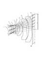
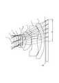
図1、図4、図7、図10、図13、図16、図19、図22、図25、及び図28はそれぞれ、本実施形態の実施例1から10に係る撮像レンズの概略構成図を示している。いずれも基本的なレンズ構成は同様であるため、ここでは主に実施例1の概略構成図を参照しながら、本実施形態の撮像レンズ構成について説明する。Hereinafter, embodiments according to the present invention will be described in detail with reference to the drawings.
1, 4, 7, 10, 13, 16, 19, 22, 25, and 28 are schematic configuration diagrams of the imaging lenses according to Examples 1 to 10 of the present embodiment, respectively. Is shown. Since the basic lens configuration is the same in all cases, the configuration of the imaging lens of the present embodiment will be described here mainly with reference to the schematic configuration diagram of Example 1.
図1に示すように、本発明の一実施形態の撮像レンズは、物体側から像面側に向かって順に、正の屈折力を有する第1レンズL1と、正の屈折力を有する第2レンズL2と、負の屈折力を有する第3レンズL3と、正の屈折力を有する両面が非球面の第4レンズL4と、像面側に凸面を向けたメニスカス形状の第5レンズL5と、負の屈折力を有する両面が非球面の第6レンズL6と、負の屈折力を有する第7レンズL7がそれぞれ空気間隔を置いて配置されて構成されている。また、開口絞りSTは第1レンズL1と第2レンズL2の間に配置されており、第7レンズL7と撮像面IMGとの間にはフィルタIRが配置されている。なお、このフィルタIRは省略することも可能である。As shown in FIG. 1, an imaging lens according toan embodiment of the present invention includes a first lens L1 having a positive refractive power and a second lens having a positive refractive power in order from the object side to the image plane side. L2, a third lens L3 having negative refracting power, a fourth lens L4 having a positive refracting power and an aspherical both surfaces, a meniscus fifth lens L5 having a convex surface facing the image surface side, and negative The sixth lens L6 having an aspherical surface on both sides and the seventh lens L7 having a negative refractive power are arranged with an air gap therebetween. The aperture stop ST is disposed between the first lens L1 and the second lens L2, and the filter IR is disposed between the seventh lens L7 and the imaging surface IMG. The filter IR can be omitted.
第1レンズL1は物体側に凸面を向けたメニスカス形状であり、第2レンズL2は像面側に凸面を向けた両凸形状であり、2枚の合成屈折力は適切な正の値に設定され、光学全長を短く抑えている。また、第1レンズL1と第2レンズL2の向かい合う面の少なくとも1面を凹面で構成することで、球面収差の発生量を抑えている。従って、第1レンズL1の形状は物体側に凸面を向けたメニスカス形状に限定されず、例えば以降に説明する実施例5、7、及び10のように両凸形状でも良い。ただし、その場合は第2レンズL2の物体側の面を凹面にすることが必要となる。 The first lens L1 has a meniscus shape with the convex surface facing the object side, and the second lens L2 has a biconvex shape with the convex surface facing the image surface side, and the combined refractive power of the two lenses is set to an appropriate positive value. The overall optical length is kept short. Further, by forming at least one of the opposing surfaces of the first lens L1 and the second lens L2 as a concave surface, the amount of spherical aberration generated is suppressed. Therefore, the shape of the first lens L1 is not limited to the meniscus shape with the convex surface facing the object side, and may be a biconvex shape as in Examples 5, 7, and 10 described below, for example. However, in this case, it is necessary to make the object side surface of the second lens L2 concave.
第3レンズL3は、光軸Xの近傍で像面側に凹面を向けたメニスカス形状で、両面に非球面が形成されており、第1レンズL1、及び第2レンズL2で発生した球面収差の補正と軸上色収差の補正を行っている。また、第3レンズL3の像面側に形成した非球面は、光軸Xから離れるに従って、負の屈折力が弱まるような形状にしているため、第3レンズL3から出射する軸外光線の過剰な跳ね上がりを防止している。そのため、軸外の諸収差を良好に補正する役割も果たしている。The third lens L3 has a meniscus shape with a concave surface facing the image plane side in the vicinity of the optical axis X, and aspherical surfaces are formed on both surfaces. The third lens L3 has spherical aberration generated in the first lens L1 and the second lens L2. Correction and correction of axial chromatic aberration are performed. In addition, the aspherical surface formed on the image plane side of the third lensL3 has a shape in which the negative refractive power is weakened as the distance from the optical axisX increases. Therefore, the excess of off-axis rays emitted from the third lensL3. To prevent sudden jumps. For this reason, it also plays a role of favorably correcting various off-axis aberrations.
第4レンズL4は、光軸Xの近傍で両凸形状の正の屈折力を有する両面が非球面のレンズである。第4レンズL4の物体側の面、及び像面側の面の曲率半径の大きさは、ともに撮像レンズ全系の焦点距離の70%以上となるような緩やかな値になっている。また、非球面形状については、サグ量の変化が少ない形状に形成している。このような形状を採ることによって、軸上色収差の補正、高次の球面収差の補正、及びコマ収差の発生を抑制する。なお、第4レンズL4は光軸Xの近傍で両凸形状に限定するものではなく、例えば実施例7のように、光軸Xの近傍で物体側に凸面を向けた負の屈折力のメニスカス形状でも良いし、実施例8のように光軸Xの近傍で物体側に凸面を向けた正の屈折力のメニスカス形状でも良い。 The fourth lens L4 is a double-convex positive-sided double-sided lens in the vicinity of the optical axis X. The radius of curvature of the object-side surface and the image-side surface of the fourth lens L4 is a gentle value that is 70% or more of the focal length of the entire imaging lens system. In addition, the aspherical shape is formed in a shape with little change in the sag amount. By adopting such a shape, correction of axial chromatic aberration, correction of higher-order spherical aberration, and occurrence of coma are suppressed. The fourth lens L4 is not limited to a biconvex shape in the vicinity of the optical axis X. For example, as in Example 7, a meniscus having a negative refractive power with a convex surface facing the object side in the vicinity of the optical axis X. The shape may be a shape or a meniscus shape having a positive refractive power with a convex surface facing the object side in the vicinity of the optical axis X as in the eighth embodiment.
第5レンズL5は、像面側に凸面を向けた、弱い正の屈折力を有するメニスカス形状のレンズであって、軸外の光線を小さな屈折角で第6レンズL6に導く役割を果たしており、主に非点収差と像面湾曲の良好な補正を行っている。なお、第5レンズL5の屈折力は正に限定されるものではなく、例えば、実施例9は像面側に凹面を向けたメニスカス形状で負の屈折力を有している例である。 The fifth lens L5 is a meniscus lens having a weak positive refractive power with the convex surface facing the image surface side, and plays a role of guiding off-axis rays to the sixth lens L6 with a small refraction angle. Mainly good correction for astigmatism and curvature of field. The refractive power of the fifth lens L5 is not limited to positive. For example, Example 9 is an example having a negative refractive power in a meniscus shape with a concave surface facing the image surface side.
第6レンズL6は、光軸Xの近傍で像面側に凹面を向けたメニスカス形状のレンズであり、像面側の非球面は周辺部において凸面に変化する形状になっている。このような非球面形状によって、画面周辺部における像面湾曲と歪曲収差の良好な補正を行うとともに、撮像素子に入射する主光線の角度を適切に制御している。また、第6レンズL6は光軸Xの近傍では弱い負の屈折力として、撮像レンズ全系に与える屈折力の影響を弱め、主に収差補正用のレンズにすることが望ましいが、弱い正の屈折力を選択することも可能である。例えば、実施例9の第6レンズL6は弱い正の屈折力を持たせた例である。 The sixth lens L6 is a meniscus lens having a concave surface facing the image plane side in the vicinity of the optical axis X, and the aspherical surface on the image plane side has a shape that changes to a convex surface at the periphery. With such an aspherical shape, good correction of curvature of field and distortion at the periphery of the screen is performed, and the angle of the principal ray incident on the image sensor is appropriately controlled. In addition, it is desirable that the sixth lens L6 be a negative negative refracting power in the vicinity of the optical axis X to weaken the influence of the refracting power exerted on the entire imaging lens system to be a lens mainly used for aberration correction. It is also possible to select the refractive power. For example, the sixth lens L6 of Example 9 is an example having a weak positive refractive power.
第7レンズL7は、光軸Xの近傍で負の屈折力を有する両面に非球面が形成されたレンズである。最も像面側に配置される第7レンズL7を負の屈折力にすることで適切なバックフォーカスを確保している。なお、第7レンズL7は光軸Xの近傍で負の屈折力を有していれば良く、実施例1、2、5、7、8、および9は光軸Xの近傍で両凹形状であるが、実施例3、4のように、光軸Xの近傍で像面側に凹面を向けたメニスカス形状、実施例6、10のように、光軸Xの近傍で像面側に凸面を向けたメニスカス形状であっても良い。特に、光軸Xの近傍で像面側を凹面にする場合は、像面側の非球面形状を周辺部で凸形状に変化するように形成することで、主に歪曲収差および像面湾曲を補正する効果と、撮像素子へ入射する光線の角度を制御する効果を高めることができる。 The seventh lens L7 is a lens in which aspheric surfaces are formed on both surfaces having negative refractive power in the vicinity of the optical axis X. An appropriate back focus is ensured by setting the seventh lens L7 disposed closest to the image plane to a negative refractive power. The seventh lens L7 only needs to have a negative refractive power in the vicinity of the optical axis X, and Examples 1, 2, 5, 7, 8, and 9 are biconcave in the vicinity of the optical axis X. However, as in Examples 3 and 4, a meniscus shape with the concave surface facing the image plane side in the vicinity of the optical axis X, and a convex surface on the image plane side in the vicinity of the optical axis X as in Examples 6 and 10, respectively. It may be a meniscus shape. In particular, in the case where the image surface side is concave in the vicinity of the optical axis X, the aspherical shape on the image surface side is changed to a convex shape at the peripheral part, so that mainly distortion aberration and curvature of field are formed. The effect of correcting and the effect of controlling the angle of the light beam incident on the image sensor can be enhanced.
また、本発明の撮像レンズは、以下の条件式(1)から(8)を満足する。
(1)0<f12
(2)0.6<f12/f<1.3
(3)−2.2<f3/f<−1.0
(4)0.6<f45/f<2.2
(5)−2.0<f67/f<−0.6
(6)50<νd1<70
(7)50<νd2<70
(8)20<νd3<30
ただし、
f:撮像レンズ全系の焦点距離
f3:第3レンズL3の焦点距離
f12:第1レンズL1と第2レンズL2の合成焦点距離
f45:第4レンズL4と第5レンズL5の合成焦点距離
f67:第6レンズL6と第7レンズL7の合成焦点距離
νd1:第1レンズL1のd線に対するアッベ数
νd2:第2レンズL2のd線に対するアッベ数
νd3:第3レンズL3のd線に対するアッベ数The imaging lens of the present invention satisfies the following conditional expressions (1) to (8).
(1) 0 <f12
(2) 0.6 <f12 / f <1.3
(3) -2.2 <f3 / f <-1.0
(4) 0.6 <f45 / f <2.2
(5) -2.0 <f67 / f <-0.6
(6) 50 <νd1 <70
(7) 50 <νd2 <70
(8) 20 <νd3 <30
However,
f: focal length of the entire imaging lens system f3: focal length of the third lens L3 f12: combined focal length of the first lens L1 and second lens L2 f45: combined focal length of the fourth lens L4 and fifth lens L5 f67: Combined focal length νd1: sixth lens L6 and seventh lens L7 Abbe number νd2 with respect to d line of first lens L1: Abbe number νd3 with respect to d line of second lens L2: Abbe number with respect to d line of third lens L3
条件式(1)を満足することで、第1レンズL1と第2レンズL2との合成屈折力が正の値となり光学全長の短縮が図られる。 When the conditional expression (1) is satisfied, the combined refractive power of the first lens L1 and the second lens L2 becomes a positive value, and the total optical length is shortened.
条件式(2)を満足することで、撮像レンズ全系の焦点距離に対する第1レンズL1と第2レンズL2との合成焦点距離が適切な範囲となり、光学全長の短縮と合わせて球面収差を良好に補正する。 By satisfying the conditional expression (2), the combined focal length of the first lens L1 and the second lens L2 with respect to the focal length of the entire imaging lens system is in an appropriate range, and the spherical aberration is excellent together with the shortening of the optical total length. To correct.
条件式(3)を満足することで、撮像レンズ全系の焦点距離に対する第3レンズL3の負の焦点距離が適切な範囲となり、光学全長の短縮と合わせて色収差を良好に補正する。 By satisfying conditional expression (3), the negative focal length of the third lens L3 with respect to the focal length of the entire imaging lens system is in an appropriate range, and chromatic aberration is corrected well in conjunction with shortening of the optical total length.
条件式(4)を満足することで、撮像レンズ全系の焦点距離に対する第4レンズL4と第5レンズL5との正の合成焦点距離が適切な範囲となり、軸上色収差、コマ収差、像面湾曲を良好に補正する。 By satisfying conditional expression (4), the positive combined focal length of the fourth lens L4 and the fifth lens L5 with respect to the focal length of the entire imaging lens system is in an appropriate range, and axial chromatic aberration, coma aberration, image plane Corrects curvature well.
条件式(5)を満足することで、撮像レンズ全系の焦点距離に対する第6レンズL6と第7レンズL7との負の合成焦点距離が適切な範囲となり、歪曲収差、像面湾曲、軸上色収差を良好に補正する。 By satisfying the conditional expression (5), the negative combined focal length of the sixth lens L6 and the seventh lens L7 with respect to the focal length of the entire imaging lens system is in an appropriate range, and distortion aberration, field curvature, on-axis Corrects chromatic aberration well.
条件式(6)から(8)を満足することで、色収差を良好に補正する。 By satisfying conditional expressions (6) to (8), chromatic aberration is corrected well.
本実施形態では、すべてのレンズ面を非球面で形成している。これらのレンズ面に採用する非球面形状は光軸方向の軸をZ、光軸に直交する方向の高さをH、円錐係数をk、非球面係数をA4、A6、A8、A10、A12、A14、A16としたとき次式により表わされる。 In the present embodiment, all lens surfaces are aspherical. The aspherical shape adopted for these lens surfaces is Z in the optical axis direction, H in the direction perpendicular to the optical axis, k in the conical coefficient, A4, A6, A8, A10, A12, When A14 and A16 are set, they are expressed by the following formula.

次に本実施の形態に係る撮像レンズの実施例を示す。各実施例において、fは撮像レンズ系全体の焦点距離を、FnoはFナンバーを、ωは半画角を、ihは最大像高を、TTLは光学全長をそれぞれ示す。また、iは物体側から数えた面番号、rは曲率半径、dは光軸上のレンズ面間の距離(面間隔)、Ndはd線(基準波長)に対する屈折率、νdはd線に対するアッベ数をそれぞれ示す。なお、非球面に関しては、面番号iの後に*(アスタリスク)の符号を付加して示す。また、光学全長TTLは第7レンズL7と撮像面IMGとの間に配置されたフィルタIRを取り外した際の距離として示してある。 Next, examples of the imaging lens according to the present embodiment will be described. In each embodiment, f represents the focal length of the entire imaging lens system, Fno represents the F number, ω represents the half field angle, ih represents the maximum image height, and TTL represents the optical total length. Further, i is a surface number counted from the object side, r is a radius of curvature, d is a distance (surface interval) between lens surfaces on the optical axis, Nd is a refractive index with respect to d-line (reference wavelength), and νd is with respect to d-line. The Abbe numbers are shown. As for the aspherical surface, a surface number i is added after the symbol * (asterisk). The optical total length TTL is shown as the distance when the filter IR arranged between the seventh lens L7 and the imaging surface IMG is removed.
基本的レンズデータを以下の表1に示す。
実施例1の撮像レンズは、表11に示すように条件式(1)から(8)の全てを満たしている。 The imaging lens of Example 1 satisfies all of the conditional expressions (1) to (8) as shown in Table 11.
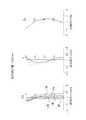
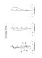
図2は実施例1の撮像レンズについて、被写体距離が無限遠の場合の球面収差(mm)、非点収差(mm)、歪曲収差(%)を示したものである。球面収差図は、g線(436nm)、F線(486nm)、e線(546nm)、d線(588nm)、C線(656nm)の各波長に対する収差量を示している。また、非点収差図はd線におけるサジタル像面S、タンジェンシャル像面Tにおける収差量を示している(図5、図8、図11、図14、図17、図20、図23、図26、図29においても同じ)。図2に示すように、各収差は良好に補正されていることが分かる。また、図3は実施例1の撮像レンズについて、撮像レンズ全体を繰り出してオートフォーカスする際、被写体距離が150mmの場合の球面収差(mm)、非点収差(mm)、歪曲収差(%)を示したものである。球面収差図は、g線(436nm)、F線(486nm)、e線(546nm)、d線(588nm)、C線(656nm)の各波長に対する収差量を示している。また、非点収差図はd線におけるサジタル像面S、タンジェンシャル像面Tにおける収差量を示している(図6、図9、図12、図15、図18、図21、図24、図27、図30においても同じ)。図3に示すように、至近距離の被写体を撮影する場合においても各収差は良好に補正されていることが分かる。 FIG. 2 shows spherical aberration (mm), astigmatism (mm), and distortion (%) when the subject distance is infinity for the imaging lens of Example 1. The spherical aberration diagram shows the amount of aberration for each wavelength of g-line (436 nm), F-line (486 nm), e-line (546 nm), d-line (588 nm), and C-line (656 nm). The astigmatism diagrams show the aberration amounts on the sagittal image plane S and tangential image plane T on the d line (FIGS. 5, 8, 11, 14, 17, 17, 20, 23, and FIG. 26 and FIG. 29). As shown in FIG. 2, it can be seen that each aberration is well corrected. FIG. 3 shows the spherical aberration (mm), astigmatism (mm), and distortion (%) when the subject distance is 150 mm when the entire imaging lens is extended and autofocused. It is shown. The spherical aberration diagram shows the amount of aberration for each wavelength of g-line (436 nm), F-line (486 nm), e-line (546 nm), d-line (588 nm), and C-line (656 nm). The astigmatism diagrams show the aberration amounts on the sagittal image plane S and tangential image plane T on the d-line (FIGS. 6, 9, 12, 15, 18, 18, 21, 24, and FIG. 27 and FIG. 30). As shown in FIG. 3, it can be seen that each aberration is well corrected even when a subject at a close distance is photographed.
さらに、全画角で80°近い広い画角を達成し、F値は2.6で比較的明るい撮像レンズ系が実現されている。また、光学全長TTLと最大像高ihとの比(TTL/2ih)は0.82であり、7枚構成でありながら小型化が図られている。 Furthermore, a wide angle of view close to 80 ° is achieved at all angles, and a relatively bright imaging lens system with an F value of 2.6 is realized. In addition, the ratio (TTL / 2ih) between the optical total length TTL and the maximum image height ih is 0.82, and downsizing is achieved despite the seven-sheet configuration.
基本的レンズデータを以下の表2に示す。
実施例2の撮像レンズは、表11に示すように条件式(1)から(8)の全てを満たしている。 The imaging lens of Example 2 satisfies all of the conditional expressions (1) to (8) as shown in Table 11.
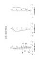
図5は実施例2の撮像レンズの被写体距離が無限遠の場合の収差図を示したものであり、図6は実施例2の撮像レンズについて、撮像レンズ全体を繰り出してオートフォーカスする際、被写体距離が150mmの場合の収差図を示したものである。図5、図6に示すように、各収差は良好に補正されていることが分かる。 FIG. 5 shows aberration diagrams when the subject distance of the imaging lens of Example 2 is infinite. FIG. 6 shows the subject when the entire imaging lens is extended and autofocused for the imaging lens of Example 2. The aberration diagram when the distance is 150 mm is shown. As shown in FIGS. 5 and 6, it can be seen that each aberration is corrected satisfactorily.
さらに、全画角で80°近い広い画角を達成し、F値は2.6で比較的明るい撮像レンズ系が実現されている。また、光学全長TTLと最大像高ihとの比(TTL/2ih)は0.80であり、7枚構成でありながら小型化が図られている。 Furthermore, a wide angle of view close to 80 ° is achieved at all angles, and a relatively bright imaging lens system with an F value of 2.6 is realized. In addition, the ratio (TTL / 2ih) between the optical total length TTL and the maximum image height ih is 0.80, and the miniaturization is achieved despite the seven-lens configuration.
基本的レンズデータを以下の表3に示す。
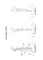
図8は実施例3の撮像レンズの被写体距離が無限遠の場合の収差図を示したものであり、図9は実施例3の撮像レンズについて、撮像レンズ全体を繰り出してオートフォーカスする際、被写体距離が150mmの場合の収差図を示したものである。図8、図9に示すように、各収差は良好に補正されていることが分かる。 FIG. 8 shows aberration diagrams when the subject distance of the imaging lens of Example 3 is infinite. FIG. 9 shows the subject when the entire imaging lens is extended and autofocused for the imaging lens of Example 3. The aberration diagram when the distance is 150 mm is shown. As shown in FIGS. 8 and 9, it can be seen that each aberration is well corrected.
さらに、全画角で80°近い広い画角を達成し、F値は2.6で比較的明るい撮像レンズ系が実現されている。また、光学全長TTLと最大像高ihとの比(TTL/2ih)は0.83であり、7枚構成でありながら小型化が図られている。 Furthermore, a wide angle of view close to 80 ° is achieved at all angles, and a relatively bright imaging lens system with an F value of 2.6 is realized. In addition, the ratio (TTL / 2ih) between the optical total length TTL and the maximum image height ih is 0.83, and downsizing is achieved even though the configuration is seven.
基本的レンズデータを以下の表4に示す。
実施例4の撮像レンズは、表11に示すように条件式(1)から(8)の全てを満たしている。 The imaging lens of Example 4 satisfies all of the conditional expressions (1) to (8) as shown in Table 11.
図11は実施例4の撮像レンズの被写体距離が無限遠の場合の収差図を示したものであり、図12は実施例4の撮像レンズについて、撮像レンズ全体を繰り出してオートフォーカスする際、被写体距離が150mmの場合の収差図を示したものである。図11、図12に示すように、各収差は良好に補正されていることが分かる。 FIG. 11 shows aberration diagrams when the subject distance of the imaging lens of Example 4 is infinite. FIG. 12 shows the subject when the entire imaging lens is extended and autofocused for the imaging lens of Example 4. The aberration diagram when the distance is 150 mm is shown. As shown in FIGS. 11 and 12, it can be seen that each aberration is corrected satisfactorily.
さらに、全画角で80°近い広い画角を達成し、F値は2.6で比較的明るい撮像レンズ系が実現されている。また、光学全長TTLと最大像高ihとの比(TTL/2ih)は0.79であり、7枚構成でありながら小型化が図られている。 Furthermore, a wide angle of view close to 80 ° is achieved at all angles, and a relatively bright imaging lens system with an F value of 2.6 is realized. In addition, the ratio (TTL / 2ih) between the optical total length TTL and the maximum image height ih is 0.79, and downsizing is achieved despite the seven-sheet configuration.
基本的レンズデータを以下の表5に示す。
実施例5の撮像レンズは、表11に示すように条件式(1)から(8)の全てを満たしている。 The imaging lens of Example 5 satisfies all of the conditional expressions (1) to (8) as shown in Table 11.
図14は実施例5の撮像レンズの被写体距離が無限遠の場合の収差図を示したものであり、図15は実施例5の撮像レンズについて、撮像レンズ全体を繰り出してオートフォーカスする際、被写体距離が150mmの場合の収差図を示したものである。図14、図15に示すように、各収差は良好に補正されていることが分かる。 FIG. 14 shows aberration diagrams when the subject distance of the imaging lens of Example 5 is infinite. FIG. 15 shows the subject when the entire imaging lens is extended and autofocused for the imaging lens of Example 5. The aberration diagram when the distance is 150 mm is shown. As shown in FIGS. 14 and 15, it can be seen that each aberration is corrected satisfactorily.
さらに、全画角で80°近い広い画角を達成し、F値は2.6で比較的明るい撮像レンズ系が実現されている。また、光学全長TTLと最大像高ihとの比(TTL/2ih)は0.80であり、7枚構成でありながら小型化が図られている。 Furthermore, a wide angle of view close to 80 ° is achieved at all angles, and a relatively bright imaging lens system with an F value of 2.6 is realized. In addition, the ratio (TTL / 2ih) between the optical total length TTL and the maximum image height ih is 0.80, and the miniaturization is achieved despite the seven-lens configuration.
基本的レンズデータを以下の表6に示す。
実施例6の撮像レンズは、表11に示すように条件式(1)から(8)の全てを満たしている。 The imaging lens of Example 6 satisfies all of the conditional expressions (1) to (8) as shown in Table 11.
図17は実施例6の撮像レンズの被写体距離が無限遠の場合の収差図を示したものであり、図18は実施例6の撮像レンズについて、撮像レンズ全体を繰り出してオートフォーカスする際、被写体距離が150mmの場合の収差図を示したものである。図17、図18に示すように、各収差は良好に補正されていることが分かる。 FIG. 17 shows aberration diagrams when the subject distance of the imaging lens of Example 6 is infinite. FIG. 18 shows the subject when the entire imaging lens is extended and autofocused for the imaging lens of Example 6. The aberration diagram when the distance is 150 mm is shown. As shown in FIGS. 17 and 18, it can be seen that each aberration is corrected satisfactorily.
さらに、全画角で80°近い広い画角を達成し、F値は2.4で明るい撮像レンズ系が実現されている。また、光学全長TTLと最大像高ihとの比(TTL/2ih)は0.80であり、7枚構成でありながら小型化が図られている。 Furthermore, a wide imaging angle close to 80 ° is achieved at all angles, and a bright imaging lens system with an F value of 2.4 is realized. In addition, the ratio (TTL / 2ih) between the optical total length TTL and the maximum image height ih is 0.80, and the miniaturization is achieved despite the seven-lens configuration.
基本的レンズデータを以下の表7に示す。
実施例7の撮像レンズは、表11に示すように条件式(1)から(8)の全てを満たしている。 The imaging lens of Example 7 satisfies all the conditional expressions (1) to (8) as shown in Table 11.
図20は実施例7の撮像レンズの被写体距離が無限遠の場合の収差図を示したものであり、図21は実施例7の撮像レンズについて、撮像レンズ全体を繰り出してオートフォーカスする際、被写体距離が150mmの場合の収差図を示したものである。図20、図21に示すように、各収差は良好に補正されていることが分かる。 FIG. 20 shows aberration diagrams when the subject distance of the imaging lens of Example 7 is infinity. FIG. 21 shows the subject when the entire imaging lens is extended and autofocused for the imaging lens of Example 7. The aberration diagram when the distance is 150 mm is shown. As shown in FIGS. 20 and 21, it can be seen that each aberration is corrected satisfactorily.
さらに、全画角で80°近い広い画角を達成し、F値は2.6で比較的明るい撮像レンズ系が実現されている。また、光学全長TTLと最大像高ihとの比(TTL/2ih)は0.81であり、7枚構成でありながら小型化が図られている。 Furthermore, a wide angle of view close to 80 ° is achieved at all angles, and a relatively bright imaging lens system with an F value of 2.6 is realized. Further, the ratio (TTL / 2ih) between the optical total length TTL and the maximum image height ih is 0.81, and the miniaturization is achieved despite the seven-sheet configuration.
基本的レンズデータを以下の表8に示す。
実施例8の撮像レンズは、表11に示すように条件式(1)から(8)の全てを満たしている。 The imaging lens of Example 8 satisfies all conditional expressions (1) to (8) as shown in Table 11.
図23は実施例8の撮像レンズの被写体距離が無限遠の場合の収差図を示したものであり、図24は実施例8の撮像レンズについて、撮像レンズ全体を繰り出してオートフォーカスする際、被写体距離が150mmの場合の収差図を示したものである。図23、図24に示すように、各収差は良好に補正されていることが分かる。 FIG. 23 shows aberration diagrams when the subject distance of the imaging lens of Example 8 is infinite. FIG. 24 shows the subject when the entire imaging lens is extended and autofocused for the imaging lens of Example 8. The aberration diagram when the distance is 150 mm is shown. As shown in FIGS. 23 and 24, it can be seen that each aberration is well corrected.
さらに、全画角で80°近い広い画角を達成し、F値は2.5で明るい撮像レンズ系が実現されている。また、光学全長TTLと最大像高ihとの比(TTL/2ih)は0.79であり、7枚構成でありながら小型化が図られている。 Further, a wide imaging angle close to 80 ° is achieved at all angles, and a bright imaging lens system with an F value of 2.5 is realized. In addition, the ratio (TTL / 2ih) between the optical total length TTL and the maximum image height ih is 0.79, and downsizing is achieved despite the seven-sheet configuration.
基本的レンズデータを以下の表9に示す。
実施例9の撮像レンズは、表11に示すように条件式(1)から(8)の全てを満たしている。 The imaging lens of Example 9 satisfies all conditional expressions (1) to (8) as shown in Table 11.
図26は実施例9の撮像レンズの被写体距離が無限遠の場合の収差図を示したものであり、図27は実施例9の撮像レンズについて、撮像レンズ全体を繰り出してオートフォーカスする際、被写体距離が150mmの場合の収差図を示したものである。図26、図27に示すように、各収差は良好に補正されていることが分かる。 FIG. 26 shows aberration diagrams when the subject distance of the imaging lens of Example 9 is infinite. FIG. 27 shows the subject when the entire imaging lens is extended and autofocused for the imaging lens of Example 9. The aberration diagram when the distance is 150 mm is shown. As shown in FIGS. 26 and 27, it can be seen that each aberration is well corrected.
さらに、全画角で80°近い広い画角を達成し、F値は2.6で比較的明るい撮像レンズ系が実現されている。また、光学全長TTLと最大像高ihとの比(TTL/2ih)は0.82であり、7枚構成でありながら小型化が図られている。 Furthermore, a wide angle of view close to 80 ° is achieved at all angles, and a relatively bright imaging lens system with an F value of 2.6 is realized. In addition, the ratio (TTL / 2ih) between the optical total length TTL and the maximum image height ih is 0.82, and downsizing is achieved despite the seven-sheet configuration.
基本的レンズデータを以下の表10に示す。
実施例10の撮像レンズは、表11に示すように条件式(1)から(8)の全てを満たしている。 The imaging lens of Example 10 satisfies all conditional expressions (1) to (8) as shown in Table 11.
図29は実施例10の撮像レンズの被写体距離が無限遠の場合の収差図を示したものであり、図30は実施例10の撮像レンズについて、撮像レンズ全体を繰り出してオートフォーカスする際、被写体距離が150mmの場合の収差図を示したものである。図29、図30に示すように、各収差は良好に補正されていることが分かる。 FIG. 29 is an aberration diagram when the subject distance of the imaging lens of the tenth embodiment is infinite. FIG. 30 shows the subject when the entire imaging lens is extended and autofocused with respect to the imaging lens of the tenth embodiment. The aberration diagram when the distance is 150 mm is shown. As shown in FIGS. 29 and 30, it can be seen that each aberration is corrected satisfactorily.
さらに、全画角で80°近い広い画角を達成し、F値は2.5で明るい撮像レンズ系が実現されている。また、光学全長TTLと最大像高ihとの比(TTL/2ih)は0.79であり、7枚構成でありながら小型化が図られている。 Further, a wide imaging angle close to 80 ° is achieved at all angles, and a bright imaging lens system with an F value of 2.5 is realized. In addition, the ratio (TTL / 2ih) between the optical total length TTL and the maximum image height ih is 0.79, and downsizing is achieved despite the seven-sheet configuration.
以上、説明したように、本発明の実施形態に係る撮像レンズは、撮影画角が全画角で80°近い広い画角を達成しつつも、撮像レンズ全体を繰り出してオートフォーカスする際、無限遠距離と至近距離の両方の撮影で収差が良好に補正され、F値は2.4から2.6の比較的明るい撮像レンズ系の実現を可能にする。また、光学全長TTLと最大像高ihとの比(TTL/2ih)は0.8のレベルを達成する小型なレンズ系の実現を可能にする。 As described above, the imaging lens according to the embodiment of the present invention achieves a wide angle of view with a full field angle of close to 80 °, but infinite when the entire imaging lens is extended and autofocused. Aberrations are well corrected in both far-distance and close-distance photography, and a relatively bright imaging lens system with an F value of 2.4 to 2.6 can be realized. Further, the ratio (TTL / 2ih) between the optical total length TTL and the maximum image height ih (TTL / 2ih) makes it possible to realize a small lens system that achieves a level of 0.8.
表11に実施例1から実施例10の条件式(1)〜(8)の値を示す。
本発明に係る7枚構成の撮像レンズによれば、小型化を維持しながら広画角化を満足し、且つ高解像度の要求を満足する撮像レンズを実現することができる。特にスマートテレビや4Kテレビなどの高機能製品への適用、ゲーム機やPCなどの情報端末機器への適用、さらには本格的なデジタルカメラ機能を備えたスマートフォンや携帯電話機、およびPDA(Personal Digital Assistant)などの携帯端末機器へ適用することで、当該製品の性能を高めることができる。 With the seven-lens imaging lens according to the present invention, it is possible to realize an imaging lens that satisfies a wide angle of view and a high resolution requirement while maintaining a small size. Application to high-performance products such as smart TVs and 4K TVs, application to information terminal devices such as game machines and PCs, and smartphones and mobile phones with full-fledged digital camera functions, and PDA (Personal Digital Assistant) ) Etc., the performance of the product can be improved.
ST 開口絞り
L1 第1レンズ
L2 第2レンズ
L3 第3レンズ
L4 第4レンズ
L5 第5レンズ
L6 第6レンズ
L7 第7レンズ
IR フィルタ
ih 最大像高
IMG 撮像面ST Aperture stop L1 1st lens L2 2nd lens L3 3rd lens L4 4th lens L5 5th lens L6 6th lens L7 7th lens IR filter ih Maximum image height IMG Imaging surface
Claims (12)
Translated fromJapanese正の屈折力を有する第1レンズと、
正または負の屈折力を有する第2レンズと、
負の屈折力を有する第3レンズと、
正または負の屈折力を有する両面が非球面の第4レンズと、
像面側に凸面を向けたメニスカス形状の第5レンズと、
正または負の屈折力を有する両面が非球面の第6レンズと、
負の屈折力を有する第7レンズがそれぞれ空気間隔を置いて配置されて構成されており、
前記第6レンズの像面側の面は、光軸近傍で像面側に凹面を向けており、光軸から離れるに従って凸面に変化する非球面形状であり、
以下の条件式(1)を満足することを特徴とする撮像レンズ。
(1)0<f12
ただし、
f12:第1レンズと第2レンズの合成焦点距離An imaging lens composed of seven lenses for forming an image of a subject on a solid-state imaging device, in order from the object side to the image plane side,
A first lens having a positive refractive power;
A second lens having a positive or negative refractive power;
A third lens having negative refractive power;
A fourth lens having an aspherical surface on both sides having positive or negative refractive power;
A fifth meniscus lens with a convex surface facing the image surface side;
A sixth lens having both positive and negative refractive powers and both aspheric surfaces;
Seventh lenses having negative refractive power are arranged with an air gap betweenthem,
The image-side surface of the sixth lens has an aspherical shape that has a concave surface facing the image surface side in the vicinity of the optical axis, and changes to a convex surface as the distance from the optical axis increases.
An imaging lensthat satisfies the following conditional expression (1):
(1) 0 <f12
However,
f12: Composite focal length of the first lens and the second lens
(2)0.6<f12/f<1.3
ただし、
f12:第1レンズと第2レンズの合成焦点距離
f:撮像レンズ全系の焦点距離The imaging lens according to claim 1, wherein the following conditional expression (2) is satisfied.
(2) 0.6 <f12 / f <1.3
However,
f12: Composite focal length of the first lens and the second lens f: Focal length of the entire imaging lens system
(3)−2.2<f3/f<−1.0
ただし、
f3:第3レンズの焦点距離
f:撮像レンズ全系の焦点距離The imaging lens according to claim 1, wherein the following conditional expression (3) is satisfied.
(3) -2.2 <f3 / f <-1.0
However,
f3: focal length of the third lens f: focal length of the entire imaging lens system
(4)0.6<f45/f<2.2
ただし、
f45:第4レンズと第5レンズの合成焦点距離
f:撮像レンズ全系の焦点距離The imaging lens according to claim 1, wherein the following conditional expression (4) is satisfied.
(4) 0.6 <f45 / f <2.2
However,
f45: the combined focal length of the fourth lens and the fifth lens f: the focal length of the entire imaging lens system
(5)−2.0<f67/f<−0.6
ただし、
f67:第6レンズと第7レンズの合成の焦点距離
f:撮像レンズ全系の焦点距離The imaging lens according to claim 1, wherein the following conditional expression (5) is satisfied.
(5) -2.0 <f67 / f <-0.6
However,
f67: Focal length of the composite of the sixth lens and the seventh lens f: Focal length of the entire imaging lens system
(6)50<νd1<70
(7)50<νd2<70
(8)20<νd3<30
ただし、
νd1:第1レンズのd線に対するアッベ数
νd2:第2レンズのd線に対するアッベ数
νd3:第3レンズのd線に対するアッベ数The imaging lens according to claim 1, wherein the following conditional expressions (6) to (8) are satisfied.
(6) 50 <νd1 <70
(7) 50 <νd2 <70
(8) 20 <νd3 <30
However,
νd1: Abbe number of d-line of the first lens νd2: Abbe number of d-line of the second lens νd3: Abbe number of d-line of the third lens
正の屈折力を有する第1レンズと、 A first lens having a positive refractive power;
正または負の屈折力を有する第2レンズと、 A second lens having a positive or negative refractive power;
負の屈折力を有する第3レンズと、 A third lens having negative refractive power;
正または負の屈折力を有する両面が非球面の第4レンズと、 A fourth lens having an aspherical surface on both sides having positive or negative refractive power;
像面側に凸面を向けたメニスカス形状の第5レンズと、 A fifth meniscus lens with a convex surface facing the image surface side;
正または負の屈折力を有する両面が非球面の第6レンズと、 A sixth lens having both positive and negative refractive powers and both aspheric surfaces;
負の屈折力を有する第7レンズがそれぞれ空気間隔を置いて配置されて構成されており、 Seventh lenses having negative refractive power are arranged with an air gap between them,
以下の条件式(2)を満足することを特徴とする撮像レンズ。 An imaging lens that satisfies the following conditional expression (2):
(2)0.6<f12/f<1.3(2) 0.6 <f12 / f <1.3
ただし、However,
f12:第1レンズと第2レンズの合成焦点距離f12: Composite focal length of the first lens and the second lens
f:撮像レンズ全系の焦点距離f: Focal length of the entire imaging lens system
正の屈折力を有する第1レンズと、 A first lens having a positive refractive power;
正または負の屈折力を有する第2レンズと、 A second lens having a positive or negative refractive power;
負の屈折力を有する第3レンズと、 A third lens having negative refractive power;
正または負の屈折力を有する両面が非球面の第4レンズと、 A fourth lens having an aspherical surface on both sides having positive or negative refractive power;
像面側に凸面を向けたメニスカス形状の第5レンズと、 A fifth meniscus lens with a convex surface facing the image surface side;
正または負の屈折力を有する両面が非球面の第6レンズと、 A sixth lens having both positive and negative refractive powers and both aspheric surfaces;
負の屈折力を有する第7レンズがそれぞれ空気間隔を置いて配置されて構成されており、 Seventh lenses having negative refractive power are arranged with an air gap between them,
以下の条件式(4)を満足することを特徴とする撮像レンズ。 An imaging lens satisfying the following conditional expression (4):
(4)0.6<f45/f<2.2(4) 0.6 <f45 / f <2.2
ただし、However,
f45:第4レンズと第5レンズの合成焦点距離f45: Composite focal length of the fourth lens and the fifth lens
f:撮像レンズ全系の焦点距離f: Focal length of the entire imaging lens system
正の屈折力を有する第1レンズと、 A first lens having a positive refractive power;
正または負の屈折力を有する第2レンズと、 A second lens having a positive or negative refractive power;
負の屈折力を有する第3レンズと、 A third lens having negative refractive power;
正または負の屈折力を有する両面が非球面の第4レンズと、 A fourth lens having an aspherical surface on both sides having positive or negative refractive power;
像面側に凸面を向けたメニスカス形状の第5レンズと、 A fifth meniscus lens with a convex surface facing the image surface side;
正または負の屈折力を有する両面が非球面の第6レンズと、 A sixth lens having both positive and negative refractive powers and both aspheric surfaces;
負の屈折力を有する第7レンズがそれぞれ空気間隔を置いて配置されて構成されており、 Seventh lenses having negative refractive power are arranged with an air gap between them,
前記第4レンズは、光軸近傍で物体側に凸面を向けた両凸形状、または物体側に凸面を向けたメニスカス形状であり、 The fourth lens has a biconvex shape with a convex surface facing the object side in the vicinity of the optical axis, or a meniscus shape with a convex surface facing the object side,
前記第6レンズの像面側の面は、光軸近傍で像面側に凹面を向けており、光軸から離れるに従って凸面に変化する非球面形状であることを特徴とする撮像レンズ。 An imaging lens, wherein the image-side surface of the sixth lens has a concave surface facing the image surface in the vicinity of the optical axis and changes to a convex surface as the distance from the optical axis increases.
Priority Applications (15)
| Application Number | Priority Date | Filing Date | Title |
|---|---|---|---|
| JP2013188413AJP6167348B2 (en) | 2013-09-11 | 2013-09-11 | Imaging lens |
| CN201420027067.XUCN203965708U (en) | 2013-09-11 | 2014-01-16 | Pick-up lens |
| US14/226,856US9507125B2 (en) | 2013-09-11 | 2014-03-27 | Imaging lens |
| US15/357,329US10705318B2 (en) | 2013-09-11 | 2016-11-21 | Imaging lens |
| US15/906,611US10996436B2 (en) | 2013-09-11 | 2018-02-27 | Imaging lens |
| US15/906,677US10866392B2 (en) | 2013-09-11 | 2018-02-27 | Imaging lens |
| US15/906,507US10884219B2 (en) | 2013-09-11 | 2018-02-27 | Imaging lens |
| US16/906,611US20210398496A1 (en) | 2013-09-11 | 2020-06-19 | Display backlight smoothing based on human visual response time characterizations |
| US17/306,616US11828909B2 (en) | 2013-09-11 | 2021-05-03 | Imaging lens |
| US17/306,641US11971526B2 (en) | 2013-09-11 | 2021-05-03 | Imaging lens |
| US17/306,580US11808923B2 (en) | 2013-09-11 | 2021-05-03 | Imaging lens |
| US17/306,632US11892606B2 (en) | 2013-09-11 | 2021-05-03 | Imaging lens |
| US17/306,647US11740438B2 (en) | 2013-09-11 | 2021-05-03 | Imaging lens |
| US17/306,600US11796772B2 (en) | 2013-09-11 | 2021-05-03 | Imaging lens |
| US17/306,622US11885936B2 (en) | 2013-09-11 | 2021-05-03 | Imaging lens |
Applications Claiming Priority (1)
| Application Number | Priority Date | Filing Date | Title |
|---|---|---|---|
| JP2013188413AJP6167348B2 (en) | 2013-09-11 | 2013-09-11 | Imaging lens |
Publications (3)
| Publication Number | Publication Date |
|---|---|
| JP2015055728A JP2015055728A (en) | 2015-03-23 |
| JP2015055728A5 JP2015055728A5 (en) | 2016-09-23 |
| JP6167348B2true JP6167348B2 (en) | 2017-07-26 |
Family
ID=51926269
Family Applications (1)
| Application Number | Title | Priority Date | Filing Date |
|---|---|---|---|
| JP2013188413AActiveJP6167348B2 (en) | 2013-09-11 | 2013-09-11 | Imaging lens |
Country Status (3)
| Country | Link |
|---|---|
| US (13) | US9507125B2 (en) |
| JP (1) | JP6167348B2 (en) |
| CN (1) | CN203965708U (en) |
Families Citing this family (144)
| Publication number | Priority date | Publication date | Assignee | Title |
|---|---|---|---|---|
| TWI438471B (en)* | 2011-08-24 | 2014-05-21 | Largan Precision Co Ltd | Optical image capturing lenses |
| JP5924121B2 (en)* | 2012-05-22 | 2016-05-25 | 株式会社オプトロジック | Imaging lens |
| TWI449947B (en) | 2012-08-13 | 2014-08-21 | Largan Precision Co Ltd | Image lens assembly system |
| JP6144973B2 (en) | 2013-06-21 | 2017-06-07 | カンタツ株式会社 | Imaging lens |
| JP6167348B2 (en) | 2013-09-11 | 2017-07-26 | カンタツ株式会社 | Imaging lens |
| US10018805B2 (en)* | 2013-10-14 | 2018-07-10 | Samsung Electro-Mechanics Co., Ltd. | Lens module |
| JP2015114569A (en)* | 2013-12-13 | 2015-06-22 | 富士フイルム株式会社 | Imaging lens and imaging device provided with imaging lens |
| JP2015175876A (en)* | 2014-03-13 | 2015-10-05 | 富士フイルム株式会社 | Imaging lens and imaging apparatus including imaging lens |
| JP6265334B2 (en) | 2014-03-20 | 2018-01-24 | 株式会社オプトロジック | Imaging lens |
| KR101627133B1 (en) | 2014-03-28 | 2016-06-03 | 삼성전기주식회사 | Lens module |
| JP6278354B2 (en) | 2014-04-15 | 2018-02-14 | 株式会社オプトロジック | Imaging lens |
| JP6319765B2 (en)* | 2014-07-02 | 2018-05-09 | 株式会社オプトロジック | Imaging lens |
| KR101630048B1 (en)* | 2014-07-22 | 2016-06-13 | 삼성전기주식회사 | Optical system |
| TWI507723B (en) | 2014-08-01 | 2015-11-11 | Largan Precision Co Ltd | Imaging optical lens group, image capturing device and electronic device |
| TWI510804B (en) | 2014-08-01 | 2015-12-01 | Largan Precision Co Ltd | Image capturing optical lens group, image capturing device and electronic device |
| US9392188B2 (en)* | 2014-08-10 | 2016-07-12 | Corephotonics Ltd. | Zoom dual-aperture camera with folded lens |
| KR101719878B1 (en) | 2014-12-10 | 2017-03-24 | 삼성전기주식회사 | Lens module |
| US10114196B2 (en) | 2015-01-06 | 2018-10-30 | Zhejiang Sunny Optics Co., Ltd. | Camera lens |
| CN108710193B (en)* | 2015-02-17 | 2020-09-01 | 大立光电股份有限公司 | Camera system and imaging device |
| TWI534467B (en)* | 2015-02-17 | 2016-05-21 | 大立光電股份有限公司 | Photographing system, image capturing unit and electronic device |
| CN109581632B (en)* | 2015-04-16 | 2021-08-31 | 大立光电股份有限公司 | Optical lens group and imaging device |
| JP6541180B2 (en)* | 2015-04-22 | 2019-07-10 | カンタツ株式会社 | Imaging lens |
| TWI669528B (en)* | 2015-06-25 | 2019-08-21 | 佳能企業股份有限公司 | Optical lens |
| TWI545366B (en) | 2015-07-01 | 2016-08-11 | 大立光電股份有限公司 | Optical camera lens group, image capturing device and electronic device |
| CN109164556B (en)* | 2015-07-01 | 2021-01-12 | 大立光电股份有限公司 | Optical camera lens assembly and image capturing device |
| TWI601997B (en)* | 2015-08-28 | 2017-10-11 | 先進光電科技股份有限公司 | Optical image capturing system |
| CN105425363B (en)* | 2015-12-24 | 2018-01-12 | 瑞声声学科技(苏州)有限公司 | Photographic optical system |
| JP5890948B1 (en)* | 2016-01-07 | 2016-03-22 | エーエーシー テクノロジーズ ピーティーイー リミテッドAac Technologies Pte.Ltd. | Imaging lens |
| JP5890947B1 (en) | 2016-01-07 | 2016-03-22 | エーエーシー テクノロジーズ ピーティーイー リミテッドAac Technologies Pte.Ltd. | Imaging lens |
| JP5951912B1 (en) | 2016-01-08 | 2016-07-13 | エーエーシー テクノロジーズ ピーティーイー リミテッドAac Technologies Pte.Ltd. | Imaging lens |
| JP5951913B1 (en)* | 2016-01-08 | 2016-07-13 | エーエーシー テクノロジーズ ピーティーイー リミテッドAac Technologies Pte.Ltd. | Imaging lens |
| KR101823223B1 (en)* | 2016-01-28 | 2018-01-29 | 삼성전기주식회사 | Optical Imaging System |
| TWI595261B (en) | 2016-02-04 | 2017-08-11 | 大立光電股份有限公司 | Optical lens group for imaging, image capturing device, and electronic device |
| KR20170093504A (en)* | 2016-02-05 | 2017-08-16 | 오필름코리아(주) | Optical System for Imaging Device |
| US9746648B1 (en)* | 2016-02-11 | 2017-08-29 | Newmax Technology Co., Ltd. | Four-piece infrared single wavelength lens system |
| JP6452643B2 (en)* | 2016-05-13 | 2019-01-16 | カンタツ株式会社 | Imaging lens |
| JP6570076B2 (en) | 2016-08-29 | 2019-09-04 | カンタツ株式会社 | Imaging lens |
| US10185127B2 (en) | 2016-09-12 | 2019-01-22 | Samsung Electro-Mechanics Co., Ltd. | Optical imaging system |
| CN106896474B (en) | 2016-12-30 | 2019-12-27 | 玉晶光电(厦门)有限公司 | Optical lens group |
| CN110119021A (en) | 2016-12-30 | 2019-08-13 | 玉晶光电(厦门)有限公司 | Optical mirror slip group |
| CN106908931B (en)* | 2016-12-30 | 2019-09-17 | 玉晶光电(厦门)有限公司 | Optical imaging lens |
| TWI629535B (en)* | 2017-02-18 | 2018-07-11 | 大立光電股份有限公司 | Image capturing optical system, image capturing device and electronic device |
| CN107153257B (en)* | 2017-05-15 | 2022-09-06 | 浙江舜宇光学有限公司 | Optical imaging system |
| TWI645228B (en)* | 2017-06-03 | 2018-12-21 | 大立光電股份有限公司 | Image capturing lens assembly, imaging apparatus and electronic device |
| CN107015347B (en)* | 2017-06-08 | 2019-06-14 | 浙江舜宇光学有限公司 | Pick-up lens |
| US11092782B2 (en)* | 2017-06-08 | 2021-08-17 | Zhejiang Sunny Optical Co., Ltd | Camera lens assembly |
| US11347030B2 (en) | 2017-06-20 | 2022-05-31 | Apple Inc. | Imaging lens system |
| TWI631382B (en) | 2017-07-19 | 2018-08-01 | 大立光電股份有限公司 | Photographing lens assembly, imaging apparatus and electronic device |
| CN109387920B (en)* | 2017-08-10 | 2021-03-16 | 声远精密光学股份有限公司 | Optical lens and shooting device |
| TWI775769B (en) | 2017-08-14 | 2022-09-01 | 佳能企業股份有限公司 | Optical lens |
| WO2019052144A1 (en)* | 2017-09-15 | 2019-03-21 | 浙江舜宇光学有限公司 | Optical imaging lens |
| JP6362289B1 (en)* | 2017-10-19 | 2018-07-25 | エーエーシー テクノロジーズ ピーティーイー リミテッドAac Technologies Pte.Ltd. | Imaging optical lens |
| CN107678137B (en)* | 2017-10-19 | 2020-04-17 | 瑞声科技(新加坡)有限公司 | Image pickup optical lens |
| CN107678134B (en)* | 2017-10-19 | 2020-04-17 | 瑞声科技(新加坡)有限公司 | Image pickup optical lens |
| CN107976772B (en)* | 2017-10-19 | 2020-05-29 | 瑞声光学解决方案私人有限公司 | Image pickup optical lens |
| CN107817584B (en)* | 2017-10-19 | 2020-01-17 | 瑞声科技(新加坡)有限公司 | Camera optics |
| JP6377831B1 (en)* | 2017-10-19 | 2018-08-22 | エーエーシー テクノロジーズ ピーティーイー リミテッドAac Technologies Pte.Ltd. | Imaging optical lens |
| CN107797236B (en)* | 2017-10-19 | 2020-04-17 | 瑞声科技(新加坡)有限公司 | Image pickup optical lens |
| CN107817579B (en)* | 2017-10-19 | 2020-10-23 | 瑞声光学解决方案私人有限公司 | Image pickup optical lens |
| JP6377234B1 (en)* | 2017-10-19 | 2018-08-22 | エーエーシー テクノロジーズ ピーティーイー リミテッドAac Technologies Pte.Ltd. | Imaging optical lens |
| CN107664817B (en)* | 2017-10-19 | 2020-02-18 | 瑞声科技(新加坡)有限公司 | Image pickup optical lens |
| CN107678135B (en)* | 2017-10-19 | 2020-09-18 | 瑞声光学解决方案私人有限公司 | Image pickup optical lens |
| CN107976790B (en)* | 2017-10-19 | 2020-05-29 | 瑞声光学解决方案私人有限公司 | Image pickup optical lens |
| JP6377235B1 (en)* | 2017-10-19 | 2018-08-22 | エーエーシー テクノロジーズ ピーティーイー リミテッドAac Technologies Pte.Ltd. | Imaging optical lens |
| CN107797232B (en)* | 2017-10-19 | 2020-02-18 | 瑞声科技(新加坡)有限公司 | Image pickup optical lens |
| CN107817581B (en)* | 2017-10-19 | 2020-02-04 | 瑞声科技(新加坡)有限公司 | Image pickup optical lens |
| CN107797231B (en)* | 2017-10-19 | 2020-01-17 | 瑞声科技(新加坡)有限公司 | Camera optics |
| JP6373470B1 (en)* | 2017-10-19 | 2018-08-15 | エーエーシー テクノロジーズ ピーティーイー リミテッドAac Technologies Pte.Ltd. | Imaging optical lens |
| CN107678136B (en)* | 2017-10-19 | 2020-05-19 | 瑞声光学解决方案私人有限公司 | Image pickup optical lens |
| CN107817585B (en)* | 2017-10-19 | 2020-01-17 | 瑞声科技(新加坡)有限公司 | Image pickup optical lens |
| CN107664821B (en)* | 2017-10-19 | 2020-05-29 | 瑞声光学解决方案私人有限公司 | Image pickup optical lens |
| CN107797229B (en)* | 2017-10-19 | 2020-09-18 | 瑞声光学解决方案私人有限公司 | Image pickup optical lens |
| CN107797239B (en)* | 2017-10-19 | 2020-09-18 | 瑞声光学解决方案私人有限公司 | Image pickup optical lens |
| CN107664820B (en)* | 2017-10-19 | 2020-02-04 | 瑞声科技(新加坡)有限公司 | Image pickup optical lens |
| CN107678132B (en)* | 2017-10-19 | 2020-09-18 | 瑞声光学解决方案私人有限公司 | Image pickup optical lens |
| CN107817580B (en)* | 2017-10-19 | 2020-10-23 | 瑞声光学解决方案私人有限公司 | Image pickup optical lens |
| CN107664818B (en)* | 2017-10-19 | 2020-05-29 | 瑞声光学解决方案私人有限公司 | Image pickup optical lens |
| CN107797238B (en)* | 2017-10-19 | 2020-04-17 | 瑞声科技(新加坡)有限公司 | Image pickup optical lens |
| CN107817583B (en)* | 2017-10-19 | 2020-02-04 | 瑞声科技(新加坡)有限公司 | Image pickup optical lens |
| CN107678138B (en)* | 2017-10-19 | 2020-01-17 | 瑞声科技(新加坡)有限公司 | Image pickup optical lens |
| CN107678131B (en)* | 2017-10-19 | 2020-03-20 | 瑞声科技(新加坡)有限公司 | Image pickup optical lens |
| JP6366151B1 (en)* | 2017-10-19 | 2018-08-01 | エーエーシー テクノロジーズ ピーティーイー リミテッドAac Technologies Pte.Ltd. | Imaging optical lens |
| WO2019080554A1 (en) | 2017-10-26 | 2019-05-02 | 浙江舜宇光学有限公司 | Optical imaging lens |
| CN107817591B (en)* | 2017-10-30 | 2020-02-04 | 瑞声科技(新加坡)有限公司 | Image pickup optical lens |
| CN107817586B (en)* | 2017-10-30 | 2020-02-04 | 瑞声科技(新加坡)有限公司 | Image pickup optical lens |
| KR101983194B1 (en)* | 2017-10-31 | 2019-05-28 | 삼성전기주식회사 | Imaging Lens System |
| CN108132512A (en)* | 2017-11-16 | 2018-06-08 | 玉晶光电(厦门)有限公司 | Optical imaging lens |
| CN107664830B (en) | 2017-11-16 | 2020-01-07 | 浙江舜宇光学有限公司 | Optical imaging lens |
| JP6497826B1 (en)* | 2017-11-18 | 2019-04-10 | エーエーシー テクノロジーズ ピーティーイー リミテッドAac Technologies Pte.Ltd. | Imaging optical lens |
| CN107976784B (en)* | 2017-11-18 | 2020-06-16 | 瑞声光学解决方案私人有限公司 | Image pickup optical lens |
| JP6576427B2 (en)* | 2017-11-18 | 2019-09-18 | エーエーシー テクノロジーズ ピーティーイー リミテッド | Imaging optical lens |
| JP6419995B1 (en)* | 2017-11-18 | 2018-11-07 | エーエーシー テクノロジーズ ピーティーイー リミテッドAac Technologies Pte.Ltd. | Imaging optical lens |
| CN108132523B (en)* | 2017-12-18 | 2020-06-16 | 瑞声光学解决方案私人有限公司 | Image pickup optical lens |
| US10641992B2 (en)* | 2017-12-18 | 2020-05-05 | AAC Technologies Pte. Ltd. | Camera optical lens |
| JP6530518B1 (en)* | 2017-12-18 | 2019-06-12 | エーエーシー テクノロジーズ ピーティーイー リミテッド | Imaging optical lens |
| CN107991755B (en)* | 2017-12-18 | 2020-06-16 | 瑞声光学解决方案私人有限公司 | Camera optics |
| TWI655474B (en) | 2017-12-22 | 2019-04-01 | 大立光電股份有限公司 | Image taking optical lens, image capturing device and electronic device |
| CN108227148B (en)* | 2018-01-19 | 2020-03-20 | 瑞声科技(新加坡)有限公司 | Image pickup optical lens |
| TWI651565B (en) | 2018-02-22 | 2019-02-21 | Largan Precision Co.,Ltd. | Optical imaging lens assembly, image capturing unit and electronic device |
| CN108254904B (en)* | 2018-03-22 | 2020-10-30 | 广东旭业光电科技股份有限公司 | Optical image capturing lens and camera shooting equipment |
| TWI660196B (en) | 2018-03-30 | 2019-05-21 | 大立光電股份有限公司 | Photographing optical lens system, image capturing unit and electronic device |
| JP6814519B2 (en)* | 2018-05-23 | 2021-01-20 | カンタツ株式会社 | Imaging lens |
| CN108663780B (en)* | 2018-08-06 | 2023-06-16 | 浙江舜宇光学有限公司 | Optical imaging lens |
| TWI663424B (en)* | 2018-08-23 | 2019-06-21 | 大立光電股份有限公司 | Photographing lens system, imaging apparatus and electronic device |
| TWI657282B (en)* | 2018-09-05 | 2019-04-21 | 大立光電股份有限公司 | Imaging lens system, image capturing unit and electronic device |
| JP2020071270A (en)* | 2018-10-29 | 2020-05-07 | ソニー株式会社 | Image capturing lens and image capturing device |
| TWI665488B (en)* | 2018-12-26 | 2019-07-11 | 大立光電股份有限公司 | Photographing optical system, image capturing unit and electronic device |
| CN109856771B (en)* | 2018-12-27 | 2021-07-30 | 瑞声光学解决方案私人有限公司 | Image pickup optical lens |
| CN109839721B (en)* | 2018-12-27 | 2020-12-22 | 瑞声光学解决方案私人有限公司 | Image pickup optical lens |
| CN109856768B (en)* | 2018-12-27 | 2020-12-22 | 瑞声光学解决方案私人有限公司 | Image pickup optical lens |
| CN109613684B (en) | 2019-02-18 | 2024-06-21 | 浙江舜宇光学有限公司 | Optical imaging lens |
| US11644642B2 (en)* | 2019-02-21 | 2023-05-09 | Samsung Electro-Mechanics Co., Ltd. | Optical imaging system |
| TWI679443B (en)* | 2019-03-20 | 2019-12-11 | 大立光電股份有限公司 | Optical imaging lens assembly, image capturing unit and electronic device |
| WO2020202965A1 (en)* | 2019-03-29 | 2020-10-08 | ソニー株式会社 | Imaging lens and imaging device |
| CN110161664B (en)* | 2019-05-08 | 2020-11-17 | 瑞声光电科技(苏州)有限公司 | Image pickup optical lens |
| CN110187471B (en)* | 2019-05-10 | 2021-08-20 | 诚瑞光学(常州)股份有限公司 | Camera optics |
| CN110262003B (en)* | 2019-06-29 | 2021-09-24 | 瑞声光学解决方案私人有限公司 | Image pickup optical lens |
| CN110398815B (en)* | 2019-06-29 | 2021-09-21 | 瑞声光学解决方案私人有限公司 | Image pickup optical lens |
| CN110221407B (en)* | 2019-06-29 | 2021-07-30 | 瑞声光学解决方案私人有限公司 | Image pickup optical lens |
| CN110262002B (en)* | 2019-06-29 | 2021-07-30 | 瑞声光学解决方案私人有限公司 | Image pickup optical lens |
| JP6650068B1 (en)* | 2019-08-07 | 2020-02-19 | OFILM.Japan株式会社 | Imaging lens, imaging device, and information terminal |
| KR102655434B1 (en)* | 2019-08-13 | 2024-04-05 | 삼성전자주식회사 | Multi-folded camera and mobile device including the same |
| CN112394576B (en)* | 2019-08-15 | 2023-01-06 | 华为技术有限公司 | A camera module and electronic equipment |
| CN110515180B (en)* | 2019-08-16 | 2020-10-30 | 瑞声通讯科技(常州)有限公司 | Image pickup optical lens |
| JP7002508B2 (en)* | 2019-08-19 | 2022-01-20 | 東京晨美光学電子株式会社 | Imaging lens |
| CN110542996B (en)* | 2019-09-27 | 2024-05-03 | 浙江舜宇光学有限公司 | Optical imaging lens group |
| CN110780424B (en)* | 2019-11-14 | 2022-10-04 | 玉晶光电(厦门)有限公司 | Optical imaging lens |
| CN110927930B (en)* | 2019-12-13 | 2021-03-12 | 诚瑞光学(常州)股份有限公司 | Image pickup optical lens |
| US12152999B2 (en)* | 2019-12-13 | 2024-11-26 | Corning Incorporated | Laser based inclusion detection system and methods |
| CN111239966B (en)* | 2020-01-20 | 2024-08-20 | 厦门力鼎光电股份有限公司 | Optical imaging lens |
| TWI743721B (en)* | 2020-03-04 | 2021-10-21 | 大立光電股份有限公司 | Imaging optical lens assembly, image capturing unit and electronic device |
| WO2021196224A1 (en)* | 2020-04-03 | 2021-10-07 | 江西晶超光学有限公司 | Optical system, lens module, and terminal device |
| JP7515302B2 (en)* | 2020-05-27 | 2024-07-12 | 東京晨美光学電子株式会社 | Imaging lens |
| CN111458844B (en)* | 2020-05-29 | 2024-11-19 | 浙江舜宇光学有限公司 | Camera lens set |
| CN111736300B (en)* | 2020-06-24 | 2025-05-09 | 江西欧菲光学有限公司 | Optical systems, imaging modules and electronic equipment |
| CN111913290B (en)* | 2020-09-11 | 2024-07-19 | 厦门力鼎光电股份有限公司 | Full-color optical imaging lens |
| CN112034599B (en)* | 2020-10-13 | 2024-12-10 | 浙江舜宇光学有限公司 | Optical imaging lens |
| US20240007612A1 (en)* | 2020-10-29 | 2024-01-04 | Beijing Boe Optoelectronics Technology Co., Ltd. | Virtual reality display method, device and storage medium |
| CN112731629B (en)* | 2021-01-25 | 2022-05-03 | 浙江舜宇光学有限公司 | Optical imaging lens |
| CN117425062A (en)* | 2021-01-25 | 2024-01-19 | 核心光电有限公司 | Lens system for compact digital camera |
| DE102021103587B4 (en)* | 2021-02-16 | 2022-09-29 | Carl Zeiss Ag | Compact telephoto lens with anomalous relative partial dispersion materials, camera and mobile device |
| US20220353489A1 (en)* | 2021-04-30 | 2022-11-03 | Microsoft Technology Licensing, Llc | Systems and methods for efficient generation of single photon avalanche diode imagery with persistence |
| CN115291382B (en)* | 2022-07-28 | 2025-05-20 | 京东方科技集团股份有限公司 | Eyepiece system and near-eye display device |
| CN115576083B (en)* | 2022-12-09 | 2023-04-18 | 江西联创电子有限公司 | Optical lens |
Family Cites Families (30)
| Publication number | Priority date | Publication date | Assignee | Title |
|---|---|---|---|---|
| JPS4838138A (en)* | 1972-09-11 | 1973-06-05 | ||
| JPS5767908A (en) | 1980-10-14 | 1982-04-24 | Canon Inc | Wide-angle zoom lens |
| JPS5875107A (en)* | 1981-10-29 | 1983-05-06 | Asahi Optical Co Ltd | telescope lens |
| JPH0627897B2 (en)* | 1985-04-19 | 1994-04-13 | 松下電器産業株式会社 | Projection lens |
| JPH0527168A (en)* | 1991-07-24 | 1993-02-05 | Konica Corp | Small-sized zoom lens |
| JPH0527169A (en)* | 1991-07-25 | 1993-02-05 | Konica Corp | Small-sized zoom lens |
| JP3103166B2 (en) | 1991-11-26 | 2000-10-23 | 富士写真光機株式会社 | Macro lens with a long exit pupil |
| JP3433266B2 (en)* | 1993-06-15 | 2003-08-04 | 三菱電機株式会社 | Projection lens |
| JPH1020193A (en)* | 1996-07-04 | 1998-01-23 | Minolta Co Ltd | Zoom lens |
| US6181484B1 (en) | 1996-11-28 | 2001-01-30 | Fuji Photo Optical Co., Ltd. | Compact two-group wide-angle zoom lens |
| JP3739529B2 (en)* | 1996-12-06 | 2006-01-25 | オリンパス株式会社 | Zoom lens |
| JP2003005070A (en)* | 2001-06-18 | 2003-01-08 | Konica Corp | Zoom lens |
| US7957074B2 (en)* | 2008-05-27 | 2011-06-07 | Fujinon Corporation | Imaging lens system and imaging apparatus using the imaging lens system |
| JP5607398B2 (en) | 2009-04-07 | 2014-10-15 | 富士フイルム株式会社 | IMAGING LENS, IMAGING DEVICE, AND PORTABLE TERMINAL DEVICE |
| JP2012155223A (en) | 2011-01-27 | 2012-08-16 | Tamron Co Ltd | Wide-angle single-focus lens |
| JP5782606B2 (en)* | 2011-07-05 | 2015-09-24 | 株式会社Gushout | Heating device, glass system, processing device and program |
| TWI438471B (en) | 2011-08-24 | 2014-05-21 | Largan Precision Co Ltd | Optical image capturing lenses |
| US9048283B2 (en)* | 2012-06-05 | 2015-06-02 | Taiwan Semiconductor Manufacturing Company, Ltd. | Hybrid bonding systems and methods for semiconductor wafers |
| TWI570467B (en) | 2012-07-06 | 2017-02-11 | 大立光電股份有限公司 | Optical image pickup system group |
| TWI449947B (en) | 2012-08-13 | 2014-08-21 | Largan Precision Co Ltd | Image lens assembly system |
| JP5963360B2 (en) | 2012-11-21 | 2016-08-03 | カンタツ株式会社 | Imaging lens |
| JP2014115456A (en)* | 2012-12-10 | 2014-06-26 | Fujifilm Corp | Imaging lens and imaging device having imaging lens |
| US9116239B1 (en)* | 2013-01-14 | 2015-08-25 | Rockwell Collins, Inc. | Low range altimeter antenna |
| JP6133068B2 (en) | 2013-01-30 | 2017-05-24 | カンタツ株式会社 | Imaging lens |
| TWI463174B (en)* | 2013-03-19 | 2014-12-01 | Sintai Optical Shenzhen Co Ltd | Zoom lens |
| JP6210494B2 (en) | 2013-03-28 | 2017-10-11 | 俊博 笹谷 | Imaging optical system and imaging apparatus |
| JP6144973B2 (en) | 2013-06-21 | 2017-06-07 | カンタツ株式会社 | Imaging lens |
| JP2015028586A (en) | 2013-07-02 | 2015-02-12 | 富士フイルム株式会社 | Imaging lens, and imaging device including imaging lens |
| JP6167348B2 (en)* | 2013-09-11 | 2017-07-26 | カンタツ株式会社 | Imaging lens |
| TWI588522B (en)* | 2014-08-01 | 2017-06-21 | 大立光電股份有限公司 | Photographing optical lens assembly, image capturing unit and electronic device |
- 2013
- 2013-09-11JPJP2013188413Apatent/JP6167348B2/enactiveActive
- 2014
- 2014-01-16CNCN201420027067.XUpatent/CN203965708U/ennot_activeExpired - Lifetime
- 2014-03-27USUS14/226,856patent/US9507125B2/enactiveActive
- 2016
- 2016-11-21USUS15/357,329patent/US10705318B2/enactiveActive
- 2018
- 2018-02-27USUS15/906,677patent/US10866392B2/enactiveActive
- 2018-02-27USUS15/906,507patent/US10884219B2/enactiveActive
- 2018-02-27USUS15/906,611patent/US10996436B2/ennot_activeExpired - Fee Related
- 2020
- 2020-06-19USUS16/906,611patent/US20210398496A1/ennot_activeAbandoned
- 2021
- 2021-05-03USUS17/306,600patent/US11796772B2/enactiveActive
- 2021-05-03USUS17/306,616patent/US11828909B2/enactiveActive
- 2021-05-03USUS17/306,641patent/US11971526B2/enactiveActive
- 2021-05-03USUS17/306,647patent/US11740438B2/enactiveActive
- 2021-05-03USUS17/306,580patent/US11808923B2/enactiveActive
- 2021-05-03USUS17/306,622patent/US11885936B2/enactiveActive
- 2021-05-03USUS17/306,632patent/US11892606B2/enactiveActive
Also Published As
| Publication number | Publication date |
|---|---|
| US20210255436A1 (en) | 2021-08-19 |
| US11796772B2 (en) | 2023-10-24 |
| US11892606B2 (en) | 2024-02-06 |
| US20180188498A1 (en) | 2018-07-05 |
| US10705318B2 (en) | 2020-07-07 |
| US11971526B2 (en) | 2024-04-30 |
| US11740438B2 (en) | 2023-08-29 |
| US20210255433A1 (en) | 2021-08-19 |
| US11885936B2 (en) | 2024-01-30 |
| CN203965708U (en) | 2014-11-26 |
| US20210398496A1 (en) | 2021-12-23 |
| US20180188497A1 (en) | 2018-07-05 |
| US11828909B2 (en) | 2023-11-28 |
| US10866392B2 (en) | 2020-12-15 |
| US20150070783A1 (en) | 2015-03-12 |
| US20210256918A1 (en) | 2021-08-19 |
| US9507125B2 (en) | 2016-11-29 |
| US11808923B2 (en) | 2023-11-07 |
| US20210255438A1 (en) | 2021-08-19 |
| US20180188499A1 (en) | 2018-07-05 |
| US20170068072A1 (en) | 2017-03-09 |
| US20210255435A1 (en) | 2021-08-19 |
| US10884219B2 (en) | 2021-01-05 |
| US20210255437A1 (en) | 2021-08-19 |
| US20210255434A1 (en) | 2021-08-19 |
| JP2015055728A (en) | 2015-03-23 |
| US10996436B2 (en) | 2021-05-04 |
Similar Documents
| Publication | Publication Date | Title |
|---|---|---|
| JP6167348B2 (en) | Imaging lens | |
| JP6105317B2 (en) | Wide-angle imaging lens | |
| JP6257081B2 (en) | Imaging lens | |
| JP6376561B2 (en) | Imaging lens | |
| JP6573315B2 (en) | Imaging lens | |
| JP6358757B2 (en) | Imaging lens | |
| JP6351171B2 (en) | Imaging lens with 7 optical elements | |
| JP6144973B2 (en) | Imaging lens | |
| JP5963360B2 (en) | Imaging lens | |
| JP6358752B2 (en) | Imaging lens | |
| JP6300410B2 (en) | Imaging lens | |
| JP5800438B2 (en) | Imaging lens and imaging device provided with imaging lens | |
| JP6332851B2 (en) | Imaging lens | |
| JP6066179B2 (en) | Imaging lens | |
| US9599791B2 (en) | Imaging lens and imaging device provided with the same | |
| JP6324824B2 (en) | Imaging lens | |
| WO2014155467A1 (en) | Imaging lens and imaging device provided with imaging lens | |
| JP2016095460A (en) | Imaging lens and imaging device provided with imaging lens | |
| JP2016114803A (en) | Image capturing lens and image capturing device having the same | |
| US20140293449A1 (en) | Imaging lens and imaging apparatus including the imaging lens | |
| JP2017187565A (en) | Image capturing lens | |
| JP2016085390A (en) | Imaging lens and imaging device provided with imaging lens | |
| JP6150317B2 (en) | Imaging lens and imaging device provided with imaging lens | |
| JP5917431B2 (en) | Imaging lens and imaging device provided with imaging lens | |
| JP2014211586A (en) | Image pickup lens |
Legal Events
| Date | Code | Title | Description |
|---|---|---|---|
| A521 | Request for written amendment filed | Free format text:JAPANESE INTERMEDIATE CODE: A523 Effective date:20160808 | |
| A621 | Written request for application examination | Free format text:JAPANESE INTERMEDIATE CODE: A621 Effective date:20160808 | |
| RD02 | Notification of acceptance of power of attorney | Free format text:JAPANESE INTERMEDIATE CODE: A7422 Effective date:20160808 | |
| RD02 | Notification of acceptance of power of attorney | Free format text:JAPANESE INTERMEDIATE CODE: A7422 Effective date:20160924 | |
| RD04 | Notification of resignation of power of attorney | Free format text:JAPANESE INTERMEDIATE CODE: A7424 Effective date:20160926 | |
| A977 | Report on retrieval | Free format text:JAPANESE INTERMEDIATE CODE: A971007 Effective date:20170419 | |
| A131 | Notification of reasons for refusal | Free format text:JAPANESE INTERMEDIATE CODE: A132 Effective date:20170502 | |
| A521 | Request for written amendment filed | Free format text:JAPANESE INTERMEDIATE CODE: A523 Effective date:20170512 | |
| TRDD | Decision of grant or rejection written | ||
| A01 | Written decision to grant a patent or to grant a registration (utility model) | Free format text:JAPANESE INTERMEDIATE CODE: A01 Effective date:20170530 | |
| A61 | First payment of annual fees (during grant procedure) | Free format text:JAPANESE INTERMEDIATE CODE: A61 Effective date:20170531 | |
| R150 | Certificate of patent or registration of utility model | Ref document number:6167348 Country of ref document:JP Free format text:JAPANESE INTERMEDIATE CODE: R150 | |
| S531 | Written request for registration of change of domicile | Free format text:JAPANESE INTERMEDIATE CODE: R313531 | |
| R350 | Written notification of registration of transfer | Free format text:JAPANESE INTERMEDIATE CODE: R350 | |
| R250 | Receipt of annual fees | Free format text:JAPANESE INTERMEDIATE CODE: R250 | |
| R250 | Receipt of annual fees | Free format text:JAPANESE INTERMEDIATE CODE: R250 | |
| S111 | Request for change of ownership or part of ownership | Free format text:JAPANESE INTERMEDIATE CODE: R313113 | |
| R371 | Transfer withdrawn | Free format text:JAPANESE INTERMEDIATE CODE: R371 | |
| S111 | Request for change of ownership or part of ownership | Free format text:JAPANESE INTERMEDIATE CODE: R313113 | |
| R350 | Written notification of registration of transfer | Free format text:JAPANESE INTERMEDIATE CODE: R350 | |
| R250 | Receipt of annual fees | Free format text:JAPANESE INTERMEDIATE CODE: R250 | |
| R250 | Receipt of annual fees | Free format text:JAPANESE INTERMEDIATE CODE: R250 | |
| R250 | Receipt of annual fees | Free format text:JAPANESE INTERMEDIATE CODE: R250 |