JP6164489B2 - Wiring module - Google Patents
Wiring moduleDownload PDFInfo
- Publication number
- JP6164489B2 JP6164489B2JP2014008347AJP2014008347AJP6164489B2JP 6164489 B2JP6164489 B2JP 6164489B2JP 2014008347 AJP2014008347 AJP 2014008347AJP 2014008347 AJP2014008347 AJP 2014008347AJP 6164489 B2JP6164489 B2JP 6164489B2
- Authority
- JP
- Japan
- Prior art keywords
- bus bar
- wall
- power storage
- tolerance
- piece
- Prior art date
- Legal status (The legal status is an assumption and is not a legal conclusion. Google has not performed a legal analysis and makes no representation as to the accuracy of the status listed.)
- Expired - Fee Related
Links
- 238000001514detection methodMethods0.000claimsdescription74
- 229920005989resinPolymers0.000claimsdescription43
- 239000011347resinSubstances0.000claimsdescription43
- 238000003860storageMethods0.000claimsdescription25
- 238000005452bendingMethods0.000claimsdescription5
- 238000010521absorption reactionMethods0.000claimsdescription3
- 230000001012protectorEffects0.000description38
- 229910052751metalInorganic materials0.000description12
- 239000002184metalSubstances0.000description12
- 238000000034methodMethods0.000description9
- 238000003825pressingMethods0.000description7
- 238000003780insertionMethods0.000description5
- 230000037431insertionEffects0.000description5
- 239000000463materialSubstances0.000description5
- PXHVJJICTQNCMI-UHFFFAOYSA-NNickelChemical compound[Ni]PXHVJJICTQNCMI-UHFFFAOYSA-N0.000description4
- 230000002452interceptive effectEffects0.000description3
- 238000004519manufacturing processMethods0.000description3
- 238000005192partitionMethods0.000description3
- 230000000630rising effectEffects0.000description3
- 238000005476solderingMethods0.000description3
- 229920003002synthetic resinPolymers0.000description3
- 239000000057synthetic resinSubstances0.000description3
- RYGMFSIKBFXOCR-UHFFFAOYSA-NCopperChemical compound[Cu]RYGMFSIKBFXOCR-UHFFFAOYSA-N0.000description2
- 229910000881Cu alloyInorganic materials0.000description2
- ATJFFYVFTNAWJD-UHFFFAOYSA-NTinChemical compound[Sn]ATJFFYVFTNAWJD-UHFFFAOYSA-N0.000description2
- 229910052782aluminiumInorganic materials0.000description2
- XAGFODPZIPBFFR-UHFFFAOYSA-NaluminiumChemical compound[Al]XAGFODPZIPBFFR-UHFFFAOYSA-N0.000description2
- 229910052802copperInorganic materials0.000description2
- 239000010949copperSubstances0.000description2
- 230000000694effectsEffects0.000description2
- 238000012423maintenanceMethods0.000description2
- 229910052759nickelInorganic materials0.000description2
- 230000000149penetrating effectEffects0.000description2
- 230000002093peripheral effectEffects0.000description2
- 238000010248power generationMethods0.000description2
- 238000004080punchingMethods0.000description2
- 239000010935stainless steelSubstances0.000description2
- 229910001220stainless steelInorganic materials0.000description2
- 239000006096absorbing agentSubstances0.000description1
- 230000008878couplingEffects0.000description1
- 238000010168coupling processMethods0.000description1
- 238000005859coupling reactionMethods0.000description1
- 230000013011matingEffects0.000description1
- 238000005259measurementMethods0.000description1
- 238000012544monitoring processMethods0.000description1
- 238000000465mouldingMethods0.000description1
- 230000003014reinforcing effectEffects0.000description1
- 238000009423ventilationMethods0.000description1
Images


Classifications
- Y—GENERAL TAGGING OF NEW TECHNOLOGICAL DEVELOPMENTS; GENERAL TAGGING OF CROSS-SECTIONAL TECHNOLOGIES SPANNING OVER SEVERAL SECTIONS OF THE IPC; TECHNICAL SUBJECTS COVERED BY FORMER USPC CROSS-REFERENCE ART COLLECTIONS [XRACs] AND DIGESTS
- Y02—TECHNOLOGIES OR APPLICATIONS FOR MITIGATION OR ADAPTATION AGAINST CLIMATE CHANGE
- Y02E—REDUCTION OF GREENHOUSE GAS [GHG] EMISSIONS, RELATED TO ENERGY GENERATION, TRANSMISSION OR DISTRIBUTION
- Y02E60/00—Enabling technologies; Technologies with a potential or indirect contribution to GHG emissions mitigation
- Y02E60/10—Energy storage using batteries
Landscapes
- Connections Arranged To Contact A Plurality Of Conductors (AREA)
- Secondary Cells (AREA)
- Battery Mounting, Suspending (AREA)
- Connection Of Batteries Or Terminals (AREA)
Description
Translated fromJapanese本発明は、配線モジュールに関する。 The present invention relates to a wiring module.
電気自動車やハイブリッド車用の電池モジュールは、正極及び負極の電極端子を有し、扁平な形状の複数の単電池を電極端子を有する面における短径方向に並べて配列して構成されている。これら複数の単電池は、隣り合う単電池の電極端子間がバスバーで接続されることにより、直列や並列に接続されるようになっている。 Battery modules for electric vehicles and hybrid vehicles have positive and negative electrode terminals, and are configured by arranging a plurality of flat unit cells side by side in the minor axis direction on the surface having the electrode terminals. The plurality of unit cells are connected in series or in parallel by connecting the electrode terminals of adjacent unit cells with a bus bar.
このようなバスバー取り付け作業を簡素化するために、従来、複数のバスバーを絶縁樹脂製の保持部材に一体的に保持した配線モジュールを複数の単電池(単電池群)に一括に装着することが行われている。 In order to simplify such a bus bar mounting operation, conventionally, a wiring module in which a plurality of bus bars are integrally held by a holding member made of insulating resin can be collectively attached to a plurality of single cells (single cell group). Has been done.
また、単電池に接続される各バスバーには検知端子が重ねられ、各単電池の電圧や温度等の状態が検知されるようになっている。この検知端子に電線の一端側(芯線)が接続されるとともに、他端側がECU(電子制御ユニット)等に接続されることにより、各単電池の状態が検出される(特許文献1参照)。 Each bus bar connected to the unit cell is overlapped with a detection terminal so that the voltage, temperature, etc. of each unit cell are detected. One end side (core wire) of the electric wire is connected to the detection terminal, and the other end side is connected to an ECU (electronic control unit) or the like, thereby detecting the state of each unit cell (see Patent Document 1).
ここで、電線を外部に設けたECU等に接続する構成では、各単電池からECUまでの引き回し距離が長くなり、電線のインピーダンスが高くなる上、各単電池からECUまでの距離がそれぞれ異なるため、測定精度が低くなるという懸念がある。そこで、ECU等を電池モジュールと一体化し、電線の引き回し距離を短くすることが考えられる。 Here, in the configuration in which the electric wire is connected to an ECU or the like provided outside, the routing distance from each unit cell to the ECU becomes longer, the impedance of the electric wire becomes higher, and the distance from each unit cell to the ECU is different. There is a concern that the measurement accuracy will be low. In view of this, it is conceivable to integrate the ECU and the like with the battery module to shorten the distance of the electric wires.
このようにECU等を電池モジュールと一体に設ける場合には、電線と検知端子との接続作業を簡素化するべく、例えばバスバーに検出用の接続片を一体的に設け、ECU等の回路基板に直接接続する構成が提案されている(特許文献2参照)。 Thus, when the ECU or the like is provided integrally with the battery module, for example, a detection connection piece is provided integrally on the bus bar and the circuit board such as the ECU is provided in order to simplify the connection work between the electric wire and the detection terminal. A configuration for direct connection has been proposed (see Patent Document 2).
ところで、例えば特許文献1には、複数の樹脂製のバスバー絶縁部材をバスバーを介して相互に連結することにより、各バスバー絶縁部材とバスバーとを相対的に移動可能とした保持部材が開示されている。換言すれば、バスバーおよびバスバーに重ねられた検知端子は、複数の単電池の電極端子間における製造公差、及び、組み付け公差を吸収可能な状態で保持部材に保持されている。 By the way, for example,
しかし、このように公差吸収可能な状態の検知端子に接続片を一体に設け、その接続片をECU等の回路基板に直接接続すると、検知端子およびバスバーの移動がECU等の回路基板により規制されるため、電極端子間における製造公差、及び、組み付け公差を吸収できなくなり、配線モジュールの単電池群への取り付けの際に不具合が生じることが懸念される。 However, when the connection piece is integrally provided on the detection terminal in such a state capable of absorbing the tolerance and the connection piece is directly connected to the circuit board such as the ECU, the movement of the detection terminal and the bus bar is restricted by the circuit board such as the ECU. Therefore, manufacturing tolerances and assembly tolerances between the electrode terminals cannot be absorbed, and there is a concern that problems may occur when the wiring module is attached to the unit cell group.
そこで、検知端子の接続片に、撓み変形することにより公差を吸収可能な公差吸収部を設けることにより、検知端子の本体部分およびバスバーを移動可能な構成とすることが考えられる。しかし、そのような構成とすると、検知端子およびバスバーを電極とボルト締結する接続作業の際に、公差吸収部が撓み変形して電極側に倒れ込み、作業の邪魔になるという問題がある。 In view of this, it is conceivable to provide a configuration in which the main body portion of the detection terminal and the bus bar can be moved by providing a tolerance absorbing portion capable of absorbing tolerance by bending deformation in the connection piece of the detection terminal. However, with such a configuration, there is a problem in that the tolerance absorbing portion is bent and deformed and falls to the electrode side during the connecting operation of fastening the detection terminal and the bus bar to the electrode and the bolt, thereby obstructing the operation.
本発明は上記のような事情に基づいて完成されたものであって、検知部材の接続片に撓み変形可能な公差吸収部を設けた場合でも、検知部材およびバスバーを電極とボルト締結する際に、公差吸収部が邪魔になることがない配線モジュールを提供することを目的とする。 The present invention has been completed based on the above circumstances, and even when the detecting member and the bus bar are fastened to the electrode and the bolt even when the connecting piece of the detecting member is provided with a bendable and deformable tolerance absorbing portion. An object of the present invention is to provide a wiring module in which the tolerance absorbing portion does not get in the way.
上記課題を解決するための本発明は、正極および負極の電極端子を有する蓄電素子を複数並べてなる蓄電素子群に取り付けられる配線モジュールであって、隣り合う前記蓄電素子の前記電極端子間を電気的に接続する複数のバスバーと、前記バスバーに重ねられる本体部と、この本体部と一体に設けられるとともに前記蓄電素子の状態を検出する電子制御ユニットに接続される接続片と、を有する複数の検知部材と、前記バスバーを保持するバスバー保持部を有するとともに前記蓄電素子群に対して前記蓄電素子の並び方向について公差吸収可能に取り付けられる絶縁樹脂製の保持部材と、を備え、前記接続片は、撓み変形することにより前記蓄電素子の並び方向について公差吸収可能な公差吸収部を有しており、当該公差吸収部は前記本体部と交差する方向に延びており、前記保持部材は、前記公差吸収部が前記バスバー保持部側に倒れ込むことを抑制する接続片保持部を有していることを特徴としている。The present invention for solving the above problems is a wiring module attached to a power storage element group in which a plurality of power storage elements having positive and negative electrode terminals are arranged, and electrically connects the electrode terminals of adjacent power storage elements. A plurality of bus bars connected to the bus bar, a main body portion overlaid on the bus bar, and a connection piece provided integrally with the main body portion and connected to an electronic control unit for detecting the state of the power storage element. And a holding member made of an insulating resin that has a bus bar holding portion for holding the bus bar and is attached to the power storage element group so that tolerance can be absorbed with respect to the direction in which the power storage elements are arranged. has a tolerance absorbable tolerance absorbing unit for the arrangement direction of the storage element by bending deformation,the tolerance absorbing portion said body Extends in a direction intersecting, the holding member is characterized in that the tolerance absorber has connecting piece holding portion prevents the fall down to the busbar holding portionside.
上記構成によれば、接続片に設けられた撓み変形可能な公差吸収部は、保持部材に設けられた接続片保持部によりバスバー保持部側に倒れ込むことが抑制される構成であるから、検知部材の本体部およびバスバーを電極とボルト締結する際に、公差吸収部が干渉して接続作業の邪魔になることを防止することができる。 According to the above configuration, the tolerance absorbing portion capable of bending deformation provided on the connection piece is configured to be prevented from falling to the busbar holding portion side by the connection piece holding portion provided on the holding member. When the main body portion and the bus bar are fastened with the electrodes and the bolts, it is possible to prevent the tolerance absorbing portion from interfering with the connection work.
上記配線モジュールは、以下の構成を有することが好ましい。 The wiring module preferably has the following configuration.
接続片保持部は、バスバー保持部内に設けられて公差吸収部に沿って延びる支持壁である構成としてもよい。The connection piece holding part may be a support wall provided in the bus bar holding part and extending along the tolerance absorbing part.
上記構成によれば、本発明の具体的構成を実現可能である。すなわち、公差吸収部は支持壁によりバスバー保持部側に倒れ込むことが抑制される構成であるから、ボルト締結作業時に公差吸収部が干渉することを防止できる。 According to the above configuration, the specific configuration of the present invention can be realized. That is, since the tolerance absorbing portion is configured to be prevented from falling to the bus bar holding portion side by the support wall, it is possible to prevent the tolerance absorbing portion from interfering during the bolt fastening operation.
また、前記電子制御ユニットは、前記保持部材に対して前記蓄電素子の並び方向について移動可能に一体的に取り付けられる構成としてもよい。 The electronic control unit may be integrally attached to the holding member so as to be movable in the direction in which the power storage elements are arranged.
上記構成によれば、蓄電素子の並び方向について公差吸収可能とされた保持部材に対して電子制御ユニットを取り付けた場合でも、電子制御ユニットは保持部材に対して蓄電素子の並び方向について移動可能とされているから、保持部材は電子制御ユニットに移動を規制されることなく、蓄電素子群に対して公差吸収可能に取り付け可能である。 According to the above configuration, even when the electronic control unit is attached to the holding member that is capable of absorbing tolerance in the direction in which the storage elements are arranged, the electronic control unit can move in the direction in which the storage elements are arranged with respect to the holding member. Therefore, the holding member can be attached to the power storage element group so as to absorb tolerance without being restricted by the electronic control unit.
さらに、電子制御ユニットは、蓄電素子の状態を検出可能な検出回路基板を有し、複数の検知部材は、接続片を所定位置に並べて保持可能な位置決め部材によって検出回路基板に対して一括に取り付けられる構成としてもよい。 Further, the electronic control unit has a detection circuit board capable of detecting the state of the power storage element, and the plurality of detection members are attached to the detection circuit board in a lump by a positioning member that can hold the connection pieces in a predetermined position. It is good also as a structure to be made.
このような構成とすると、検知部材の取り付け作業が容易になり、組み立て作業性に優れる配線モジュールを得ることができる。 With such a configuration, it is easy to attach the detection member, and a wiring module having excellent assembly workability can be obtained.
本発明によれば、検知部材の接続片に撓み変形可能な公差吸収部を設けた場合でも、検知部材およびバスバーを電極とボルト締結する際に、公差吸収部がバスバー保持部側に倒れ込んで作業性を損なうことがない配線モジュールを提供することができる。 According to the present invention, even when the detecting member connecting piece is provided with a bendable and deformable tolerance absorbing portion, when the detecting member and the bus bar are bolted to the electrode, the tolerance absorbing portion falls into the bus bar holding portion side and works. It is possible to provide a wiring module that does not impair the performance.
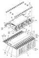
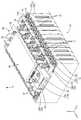
一実施形態を図1ないし図13によって説明する。本実施形態に係る電池配線モジュール20(配線モジュールの一例)は、図1に示すように、正極12A及び負極12Bの電極12を有する複数個(本実施形態では12個)の単電池11(蓄電素子の一例)を並べてなる単電池群10(蓄電素子群の一例)に取り付けられるものである。 One embodiment will be described with reference to FIGS. As shown in FIG. 1, a battery wiring module 20 (an example of a wiring module) according to the present embodiment includes a plurality (12 in the present embodiment) of single cells 11 (power storage) each having a
本実施形態の電池配線モジュール20を単電池群10に取り付けてなる電池モジュールM(図2参照)は、例えば、電気自動車又はハイブリッド自動車等の、車両(図示せず)の駆動源として使用される。単電池群10を構成する複数の単電池11は、電池配線モジュール20によって、異なる単電池11の正極12Aと負極12Bとを電気的に接続することにより、直列に接続されている。以下の説明においては、図2におけるX方向を前方とし、X方向と反対方向を後方とする。また、図2におけるY方向を右方とし、Y方向と反対方向を左方とする。さらに、図2におけるZ方向を上方とし、Z方向と反対方向を下方とする。 A battery module M (see FIG. 2) in which the
(単電池11)
単電池11は、ケースの内部に図示しない発電要素を収容してなり、扁平な直方体形状をなしている。単電池11の上面11Aには、図1に示すように、発電要素と電気的に接続された正極12Aおよび負極12Bが設けられている。以下、正極12Aおよび負極12Bを総括するときは電極12という。(Single cell 11)
The
電極12は、金属端子13(電極端子の一例)と、上方に向かって丸棒状に突出する電極ポスト14と、金属端子13をケースに固定する丸ねじ15と、を備える。金属端子13は、側面視略Z字型に構成されている。より詳細には、金属端子13は、単電池11のケースに固定される固定片13Aと、固定片13Aから直角に折れ曲がり、ケースから離れる方向に延びる接続片13Bと、接続片13Bに連続して固定片13Aと平行に延びる端子片13Cとを有している。固定片13Aおよび端子片13Cには貫通孔が設けられている。固定片13Aの貫通孔を丸ねじ15が貫通し、端子片13Cの貫通孔を電極ポスト14が貫通する。なお、電極ポスト14の表面には、ねじ山が形成されている(図示せず)。 The
複数個の単電池11は、隣り合う単電池11の電極12の極性が異なるように(正極12Aと負極12Bとが交互に配されるように)並べられている。電極ポスト14は、後述するバスバー21の端子貫通孔22に挿通され、ナット18を螺合させることによりバスバー21に固定されるようになっている。 The plurality of
また、単電池11の上面11Aの略中央には、単電池11の内部で発生したガスを外部に排出するガス排出部16が形成されている。 In addition, a
各単電池11は、隣り合う単電池11との間に配された絶縁性の合成樹脂からなるセパレータ17によって、間隔を空けて配されている。セパレータ17は、隣り合う単電池11の間に配されて各単電池11を離隔する仕切り壁17Aと、この仕切り壁17Aの4つの縁部からX軸方向に延出された延出壁17Bと、を備える。これらの仕切り壁17Aと延出壁17Bとの間に囲まれた空間内に、各単電池11が収容されている。なお、延出壁17Bのうち、単電池11の上面11Aに対向する延出壁17Bは一部切り欠かれており、金属端子13およびガス排出部16が外部に露出するように設定されている(図1参照)。なお、単電池群10の並び方向の端部に配されるセパレータ17には、外側に向けて延びる延出壁17Bは設けられていない。 Each
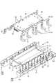
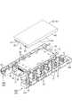
(電池配線モジュール20)
電池配線モジュール20は、単電池群10の上面10A(電極面)に取り付けられるものであって、図1に示すように、単電池11の電極12に接続される複数のバスバー21と、バスバー21を保持するバスバー保持部32を有する一対の樹脂プロテクタ30A、30Bと、バスバー21に重ねられて電気的に接続される電圧検知バスバー50と、を備える。(Battery wiring module 20)
The
(バスバー21)
バスバー21は、銅、銅合金、ステンレス鋼(SUS)、アルミニウム等からなる金属製の板材を所定の形状にプレス加工することにより形成され、全体として略長方形状をなしている。バスバー21の表面には、スズ、ニッケル等の金属がメッキされていてもよい。(Bus bar 21)
The
図3に示すように、バスバー21には、電極12の電極ポスト14が挿通される円形状をなす一対の端子貫通孔22,22が、バスバー21を貫通して形成されている。これらの端子貫通孔22は、電極ポスト14の径よりも若干大きく設定されている。端子貫通孔22内に電極ポスト14が貫通された状態でナット18が螺合されて、ナット18と金属端子13の端子片13Cとの間にバスバー21が挟まれることにより、電極12とバスバー21とが電気的に接続される。 As shown in FIG. 3, the
バスバー21の一対の長辺のうち一方側の長辺の両端付近の縁部には、それぞれ、バスバー21を後述する連結ユニット31に対して抜け止めするための抜止突部24,24が、板面から突出するように形成されている。これらの抜止突部24は、上方から見て三角形状に形成されている。 Out of the pair of long sides of the
また、バスバー21の一対の長辺のうち他方側の長辺の長さ方向の中央の縁部には、方形状に切り欠かれた凹部25が形成されている。この凹部25には、後述する連結ユニット31の係止壁37が係止されるようになっている。 In addition, a
(樹脂プロテクタ30)
絶縁樹脂材料からなる樹脂プロテクタ30(保持部材の一例)は、複数の連結ユニット31をバスバー21によって連結してなり、単電池11の並び方向(X軸方向)に細長い形状をなしている。また、一対の樹脂プロテクタ30A、30Bは、後述する電子制御ユニット60の下側ケース70により互いに連結されている(図4および図11参照)。(Resin protector 30)
A resin protector 30 (an example of a holding member) made of an insulating resin material is formed by connecting a plurality of connecting
(連結ユニット31)
連結ユニット31は、図3および図6に示すように、バスバー21を収容し保持する一対のバスバー保持部32、32を備えてなる。各バスバー保持部32は、概ねバスバー21の略半分が収容される大きさとされている。各バスバー保持部32には、バスバー21のみ、または、後述する電圧検知バスバー50がバスバー21とともに収容される。なお、図4において右手前側の第2樹脂プロテクタ30Bにおける前後方向(X軸方向)の両端部には、バスバー保持部32を1つだけ有した端部連結ユニット31A,31Bが配置されている。(Connecting unit 31)
As shown in FIGS. 3 and 6, the connecting
連結ユニット31は、図3における奥側の内側壁35と、手前側の外側壁36と、内側壁35および外側壁36をそれぞれの中央部分において連結する絶縁壁34と、が略H形状に配されるとともに、底部にバスバー21の周縁部が載置される載置部33を備えてなる。各バスバー保持部32は、上下方向(Z軸方向)および一側方(X軸方向)に向けて開放された形態をなしている。 The connecting
より詳細に説明すると、内側壁35の両側縁部には、外側壁36に向けて絶縁壁34と平行に延びる係止壁37が設けられている。係止壁37のY軸方向の幅は、絶縁壁34のY軸方向の幅の1/5程度とされており、バスバー保持部32内に挿入されたバスバー21の凹部25内に係止可能とされている。また、外側壁36の両側縁部には、内側壁35に向けて斜めに延出された斜壁38が設けられており、これにより、連結ユニット31の外側壁36側の角部は面取り形状をなしている。一対のバスバー保持部32、32は、係止壁37、内側壁35、絶縁壁34、外側壁36、および斜壁38により囲まれた各領域である。 More specifically, locking
これらの壁のうち、係止壁37、絶縁壁34、外側壁36、および斜壁38の上面は、全て面一とされている。一方、内側壁35の上面はこれらの壁よりも高くなるように設定されている。なお、これらの壁は、全て、電池配線モジュール20が単電池群10に装着された状態において電極12の電極ポスト14の上端部よりも高くなるように設定されており、電極ポスト14を保護する機能を有している。 Among these walls, the upper surfaces of the locking
絶縁壁34には、図5および図6に示すように、バスバー保持部32内に収容されたバスバー21の上側に配されて、載置部33とともにバスバー21を保持する機能を有する2つの保持突部39、39が、各バスバー保持部32の内側に向けて突出形成されている。 As shown in FIG. 5 and FIG. 6, the insulating
また、絶縁壁34および係止壁37には、バスバー保持部32内に収容された電圧検知バスバー50の上側に配されて、バスバー21とともに電圧検知バスバー50を保持する機能を有する3つの保持片40が設けられている。保持片40は、絶縁壁34に2つ、係止壁37に1つが、各バスバー保持部32の内側かつ斜め下側に向けて延出形成されている。 The insulating
外側壁36と、底部(載置部33)との間には、図3に示すように、バスバー挿入口45が形成されている。本実施形態では、バスバー挿入口45は、バスバー21を、バスバー保持部32の外側壁36側から、内側壁35側に向けて挿入可能に設けられている。 As shown in FIG. 3, a bus
内側壁35は、上述したように、他の壁部よりも上面が高くなるように、すなわち、高さ寸法が高く設定されている。図5に示すように、内側壁35の上端は、バスバー保持部32とは反対側に向けてL字形状に屈曲されており、後述する下側ケース70の押さえ片81および受け片82の間に挟持される被挟持部42とされている。また、内側壁35のうち、絶縁壁34との交差部分より上方側には、絶縁壁34の壁厚よりも広い幅のスリット43が、上下方向(Z軸方向に)に延びるように設けられている。このスリット43は、内側壁35の上端まで設けられており、被挟持部42の一部を切り欠いている。 As described above, the
さらに各バスバー保持部32には、バスバー保持部32内に収容された後述する電圧検知バスバー50の接続片54の公差吸収部56に沿って延びる一対の支持壁44が設けられている。一対の支持壁44は、絶縁壁34および係止壁37の内壁面から垂直方向に、すなわち、内側壁35に沿う方向に延設されており、これら支持壁44と内側壁35との間の隙間S1の距離は、電圧検知バスバー50の接続片54の厚みよりやや広い程度に設定されている。接続片54の公差吸収部56は、この隙間S1に収容されることにより内側壁35に沿った状態で安定的に保持され、バスバー保持部32側に倒れ込むことが防止されるようになっている(図6参照)。また、各バスバー保持部32内において並んで配されたこれら一対の支持壁44の間の距離は、電圧検知バスバー50の本体部51と接続片54との境界部分が収容可能な長さに設定されている。 Further, each bus
なお、支持壁44の上面は、絶縁壁34および係止壁37の上面と面一とされている。また、一対の支持壁44の対向端面の上端角部は、内側壁35側に向けて斜め下側に切り欠かかれており、後述する電圧検知バスバー50の接続片54を隙間S1内に案内するための案内面44Aとされている。 The upper surface of the
上述した連結ユニット31の各バスバー保持部32には、図5および図6に示すように、バスバー21の略半分が保持される。複数の連結ユニット31のうち、一の連結ユニット31とその隣に位置する連結ユニット31とは、一枚のバスバー21を介して相互に連結されている。隣り合うバスバー21は、絶縁壁34によって互いに絶縁状態に離隔される。 As shown in FIGS. 5 and 6, approximately half of the
バスバー21がバスバー保持部32に保持された状態において、係止壁37はバスバー21の凹部25に係止される係止部として作用している。なお、係止壁37とバスバー21の凹部25との間には、連結ユニット31の連結方向(X軸方向)においてクリアランスが形成されており(図6参照)、これにより、隣り合う連結ユニット31は、バスバー21に対して連結方向(X軸方向)において相対的に移動可能とされている。すなわち、複数の単電池11の電極12間における製造公差、及び、組み付け公差を吸収することができるようになっている。 In a state where the
図4において左奥に配された第1樹脂プロテクタ30Aは、複数(6つ)の連結ユニット31をバスバー21によりX軸方向に一列に連結して構成されている。一方、図4において右手前に配された第2樹脂プロテクタ30Bは、第1樹脂プロテクタ30Aよりも1つ少ない数(5つ)の連結ユニット31が連結されるとともに、X軸方向における両端部に端部連結ユニット31A,31Bが連結されており、第1樹脂プロテクタ30Aとは連結ユニット31が単電池11の一個分の幅寸法だけずれるように構成されている。 The
(電圧検知バスバー50)
樹脂プロテクタ30(連結ユニット31)の所定のバスバー保持部32内には、単電池11の電圧を検知するための電圧検知バスバー50(検知部材の一例)が配される。電圧検知バスバー50は、銅、銅合金、ステンレス鋼、アルミニウム等の金属板材を所定の形状に打ち抜き加工するとともに、プレス加工することにより形成されている。電圧検知バスバー50の表面は、スズ、ニッケル等の金属によってメッキされていてもよい。(Voltage detection bus bar 50)
A voltage detection bus bar 50 (an example of a detection member) for detecting the voltage of the
本実施形態において電圧検知バスバー50は、図9に示すように、バスバー21の約半分の大きさの略八角形をなしてバスバー21に重ねられる本体部51と、後述する検出回路基板90に接続される接続片54とを一体的に備える。 In the present embodiment, as shown in FIG. 9, the voltage
本体部51の中央付近には、電極ポスト14が挿通される端子挿通孔52がバスバー21の端子貫通孔22と重なるように形成されており、その径は電極ポスト14の径よりも若干大きく、かつ、バスバー21の端子貫通孔22よりも若干大きく設定されている。また本体部51の一縁部からは、バスバー保持部32の外側壁36の内側に圧接して本体部51をバスバー保持部32内に安定的に保持するための圧接片53が延設されている。圧接片53は、本体部51の一縁部より小さい幅を有して本体部51から延出されるとともに、先端を上方側に向けてL字形状に屈曲させることにより形成されている。 Near the center of the
また、本体部51のうち圧接片53の反対側の縁部からは、後述する検出回路基板90に接続する接続片54が延設されている。接続片54は、本体部51から垂直方向に立ち上がる基端部55と、基端部55の上縁の一部から延出された公差吸収部56と、公差吸収部56の上端においてL字形状に屈曲されて本体部51と平行に延びる引出部57と、引出部57から垂直に立ち上がり後述する検出回路基板90に接続される接続部58と、を有する。 Further, a connecting
上述した基端部55と本体部51との境界部分の両端には、一対の切欠き59が設けられており、上述した一対の支持壁44を逃がすことが可能とされている。 A pair of
また、公差吸収部56は、2つの屈曲部を有して略Z形状に打ち抜き形成されており、この公差吸収部56が撓み変形することで、X軸方向の公差を吸収できるようになっている。 Further, the
電圧検知バスバー50は、本体部51がナット18とバスバー21との間に挟まれることにより、電極12に電気的に接続される。 The voltage
一方、接続片54の引出部57のうち接続部58寄りの領域は、複数の電圧検知バスバー50を所定の位置に並べるための合成樹脂製の位置決め部材85に、インサート成形により一体化されている。位置決め部材85から導出された接続部58は、後述する電子制御ユニット60の検出回路基板90の所定位置に貫通され、はんだ付けにより接続されるようになっている。 On the other hand, a region near the
(電子制御ユニット60)
上述した連結ユニット31をバスバー21により連結した一対の樹脂プロテクタ30A、30Bの間には、図1に示すように、電子制御ユニット60が配される。電子制御ユニット60は、略直方体状のケース61の内部に、マイクロコンピュータ、素子等が搭載された検出回路基板90を収容してなり(図13参照)、単電池11の電圧・電流・温度等を検出して、各単電池11の監視制御等を行うための機能を備えた周知の構成のものである。(Electronic control unit 60)
As shown in FIG. 1, an
ケース61は、下面が開口した略矩形の箱状の上側ケース62と、略矩形の板状の下側ケース70とからなる。 The
上側ケース62のうち、前後方向(X軸方向)に沿う一対の側壁63の下端縁には、下側ケース70の押さえ片81を逃がすための複数の切欠き64が設けられている。 In the
また上側ケース62のうち、前壁65および後壁には、後述するコネクタ部92を逃がすための逃がし部66が設けられているとともに、逃がし部66の両側に、後述する下側ケース70の係止突部76に係止するための一対の係止片67が設けられている。 Further, in the
一方、図4に示すように、下側ケース70は矩形の板状の底部71を有し、底部71には、左右方向(Y軸方向)の中央部において前後方向(X軸方向)に沿って浅く窪んだ窪み部72が設けられている。底部71の前後の端縁部からは、前後方向(X軸方向)に沿って窪み部72と同幅の一対の板状の第1固定部73が互いに反対側に向けて延設されており、これらの第1固定部73には一対の固定孔74が並んで設けられている。 On the other hand, as shown in FIG. 4, the
また底部71の前後の両端縁部には、底部71の板面から垂直方向に立ち上がる一対の第2固定部75がそれぞれ設けられている。第2固定部75は、窪み部72の側壁72Aをまたぐ位置に設けられている。第2固定部75のうち、窪み部72の側壁72Aより外側に位置する部分の外面には係止突部76が設けられており、上側ケース62に設けられた係止片67がこの係止突部76に係止されることにより、上側ケース62と下側ケース70とが互いに組み付け状態とされる。また、第1固定部73の両側縁部からは、第2固定部75の外面と連なる三角形状の補強壁77が、第1固定部73の板面から立ち上がるように設けられている。 In addition, a pair of
図5に示すように、底部71のうち、前後方向(X軸方向)に沿って延びる一対の側縁部の上面には、前後方向の全域にわたって延びる突き当てリブ80がそれぞれ設けられているとともに、これらの突き当てリブ80の上面からは、外側に向けてL字形状に立ち上がる複数の押さえ片81が等間隔で設けられている。これらの押さえ片81は、下側ケース70と樹脂プロテクタ30とが組み付けられた際に、隣り合う連結ユニット31の内側壁35の間の隙間S2に対応する位置に、その隙間S2の幅より幅広に形成されている。 As shown in FIG. 5,
また、底部71のうち、前後方向(X軸方向)に沿って延びる一対の側面からは、底部71よりやや低い位置において外側に向けて延びる複数の受け片82が延出されている。受け片82は、下側ケース70と樹脂プロテクタ30とが組み付けられた際に、連結ユニット31の被挟持部42に対応する位置に、被挟持部42の幅より狭い幅で設けられている。 In addition, a plurality of receiving
図5に示すように、受け片82のうち、下側ケース70と樹脂プロテクタ30とが組み付けられた際にスリット43に対応する部分は切り欠かれており(受け片82は形成されておらず)、その切り欠かれた部分に、係止片83が延設されている。係止片83は底部71の側縁部から外側に向けて、受け片82とほぼ平行に、かつ、受け片82より突出長さがやや長く形成されており、その先端部の上面には、上方に向けて突出する係止突部83Aが設けられている。この係止突部83Aが、上述した樹脂プロテクタ30(連結ユニット31)のスリット43の上端縁部に係止することにより、下側ケース70と樹脂プロテクタ30とが一体化されるようになっている(図7参照)。 As shown in FIG. 5, the portion corresponding to the
なお、係止片83の幅は、スリット43の幅よりも狭く設定されており、これにより、係止片83とスリット43とは単電池11の並び方向(X軸方向)にクリアランスを有して係止されるようになっている(図8参照)。すなわち、下側ケース70と樹脂プロテクタ30とは、X軸方向において相対的に移動可能とされており、公差吸収可能となっている。 Note that the width of the locking
また、これら押さえ片81と受け片82とは、上下方向において重ならないように、互いにずれた位置に配されている。 Further, the
検出回路基板90は、表面にプリント配線技術により図示しない導電回路が形成されているとともに、適所に複数の貫通孔91が設けられている(図10参照)。これらの貫通孔91の一部は、電圧検知バスバー50の接続部58を貫通させるためのものであり、貫通孔91を貫通した接続部58は、例えば半田付け等公知の手法により導電回路に接続されるようになっている。また、検出回路基板90の裏面には、検出回路基板90の導電回路を相手側コネクタ(図示せず)に接続するためのコネクタ部92が、前後方向に向けて開口するように一体に設けられている。 The
(ダクト95)
図1に示すように、単電池群10の上面10Aには、単電池11内で発生したガスを外部に排気するダクト95が設けられている。ダクト95は合成樹脂材料からなり、長板状の天板部96と、天板部96のうち前後方向(X軸方向)に沿った両側縁部から下方に向けて延びる一対の側壁部97と、一対の側壁部97の両下端縁部から外側に向けて天板部96と平行に延びる突当部98を有した、断面略凹形状をなしている。天板部96の前後方向の長さは、単電池群10の並び方向の長さと同等とされている。(Duct 95)
As shown in FIG. 1, a
また、天板部96の上面には、電子制御ユニット60の固定孔74内に貫通される2対の丸棒状の取付突部99が、上方に向かって突出形成されている。この取付突部99の外周面にはネジ溝(図示せず)が設けられており、ここにナット18が螺合されることにより、電子制御ユニット60とダクト95とが一体化されるようになっている。 Further, on the top surface of the
単電池11のガス排出部16から排出されたガスは、ダクト95により形成された通気空間を通して電池モジュールMの外部に排出される。 The gas discharged from the
(電池配線モジュール20の組立方法)
次に、電池配線モジュール20の組み立て方法について説明する。(Assembly method of battery wiring module 20)
Next, a method for assembling the
まず、所定の個数の連結ユニット31を用意し、バスバー挿入口45からバスバー保持部32内にバスバー21挿入し、複数の連結ユニット31を連結状態とする(図3参照)。バスバー21は、端部が保持突部39および保持片40に上方側から係止されるとともに、抜止突部24が外側壁36の内面の下端に係止することにより、バスバー保持部32内に抜け止め状態で保持される(図5および図6参照)。 First, a predetermined number of
また、凹部25内に隣り合う連結ユニット31の各係止壁37が係止されることにより、隣り合う連結ユニット31が連結される。この時、互いに連結された連結ユニット31は、凹部25と係止壁37との間にクリアランスが設けられていることにより、その連結方向(X軸方向)において伸張可能とされる。すなわち、複数の連結ユニット31により形成された樹脂プロテクタ30は、単電池群10に取り付ける際に、X軸方向において公差吸収可能とされている。 Moreover, the
次に、上記のようにして組み立てられた一対の樹脂プロテクタ30A、30Bの間に、電子制御ユニット60の下側ケース70を取り付ける。具体的には、図4に示すように、下側ケース70の両側方から一対の樹脂プロテクタ30A、30Bを近づけ、下側ケース70の押さえ片81と受け片82との間に樹脂プロテクタ30の被挟持部42を挟み込むようにして組み付ける(図5参照)。この時、下側ケース70の係止片83が弾性変形しながら連結ユニット31のスリット43内に挿入され、先端の係止突部83Aがスリット43の上端を通過したところで弾性復帰することにより、スリット43の上端縁部に係止した状態とされる(図7参照)。これにより、図11に示すように、下側ケース70と一対の樹脂プロテクタ30A、30Bとが一体化される。 Next, the
この時、下側ケース70は、樹脂プロテクタ30に対し、前後方向(X軸方向)において移動可能なクリアランスを有している。すなわち、図8に示すように、スリット43のX軸方向の幅は係止片83のX軸方向の幅よりも大きく設定されているから、下側ケース70は樹脂プロテクタ30に対して、連結ユニット31の連結方向(X軸方向)に沿った方向に上記クリアランスの範囲内で移動可能に取り付けられている。 At this time, the
上述したように、樹脂プロテクタ30と下側ケース70とを組み付ける一方、図10に示すように、複数の電圧検知バスバー50の接続片54を一体化した位置決め部材85を、検出回路基板90の下方側から重ね合わせる。そして、電圧検知バスバー50の接続部58を検出回路基板90の所定の貫通孔91に貫通させ、はんだ付けを行うことにより、電圧検知バスバー50と検出回路基板90とを接続する(図11参照)。 As described above, the
次に、このようにして検出回路基板90と一体化され、接続された電圧検知バスバー50の本体部51を、下側ケース70と一体化された樹脂プロテクタ30(連結ユニット31)の複数のバスバー保持部32のうち、所定のバスバー保持部32内に上方から収容して、バスバー21に重ね合わせる。この時、図12に示すように、電圧検知バスバー50の接続片54の基端部55および公差吸収部56の一部は、内側壁35と支持壁44との間に形成された隙間S1内に収容する。 Next, the
一方、電圧検知バスバー50の本体部51は、圧接片53により外側壁36の内面に圧接しつつバスバー保持部32内に収容される。またこの時、本体部51は、その下面によりバスバー保持部32の保持片40を弾性変形させつつ挿入され、保持片40の下端を通過したところで、弾性復帰した保持片40により上方側への抜け止めがなされる。このように、電圧検知バスバー50の本体部51は、バスバー21に重ねらた状態において、安定した抜け止め状態とされる(図6参照)。 On the other hand, the
また、電圧検知バスバー50がバスバー21に重ね合わされた状態において、電圧検知バスバー50の接続片54は、その公差吸収部56が支持壁44により内側壁35の内面に沿った状態とされるとともに、引出部57が被挟持部42の上面に重ね合わされた状態とされている(図12参照)。 Further, in the state where the voltage
また、検出回路基板90の下面に設けられたコネクタ部92は、下側ケース70の窪み部72の上面に重ね合わされるとともに、位置決め部材85が窪み部72の両側に重ね合わされる。これにより、検出回路基板90が下側ケース70の底部71に載置された状態とされる(図13参照)。 The
次に、検出回路基板90の上方から上側ケース62を近づけ、下側ケース70に組み付ける。具体的には、上側ケース62の係止片67を下側ケース70の係止突部76に係止させることにより、上側ケース62と下側ケース70とが一体化され、検出回路基板90が内部に収容された電子制御ユニット60が完成する。また、樹脂プロテクタ30と電子制御ユニット60とが一体化された電池配線モジュール20が完成する(図1参照)。 Next, the
なおこの時、電子制御ユニット60は、上述したように、下側ケース70が樹脂プロテクタ30に対し、前後方向(X軸方向)において移動可能なクリアランスを有しているから、上記クリアランスの範囲内で前後方向に相対的に移動可能に取り付けられている。 At this time, as described above, the
次に、電極12を上に向けた状態で並べられた単電池群10の上面10Aに、ガス排出部16を覆うようにダクト95を配し、上方側から電池配線モジュール20を取り付ける。具体的には、電池配線モジュール20をダクト95の上方側から近づけ、下側ケース70の第1固定部73の固定孔74内にダクト95の取付突部99を貫通させる。また同時に、バスバー21および電圧検知バスバー50の端子貫通孔22および端子挿通孔52内に電極ポスト14を貫通させる。そして、取付突部99および電極ポスト14にナット18を螺合させることにより、ケース61とダクト95を固定するとともに隣り合う正極および負極の電極12を接続させて、電池モジュールMが完成する(図2参照)。 Next, a
(本実施形態の作用、効果)
以下、本実施形態の作用および効果について説明する。(Operation and effect of this embodiment)
Hereinafter, the operation and effect of the present embodiment will be described.
本実施形態の電池配線モジュール20によれば、接続片54の公差吸収部56は、樹脂プロテクタ30(連結ユニット31)に設けられた支持壁44によりバスバー保持部32の内側壁35の内面に沿うように保持される。換言すれば、樹脂プロテクタ30(連結ユニット31)に公差吸収部56に沿って延びる支持壁44が設けられることにより、公差吸収部56が撓み変形してバスバー保持部32側に倒れ込むことが防止されるから、電圧検知バスバー50の本体部51とバスバー21とを電極ポスト14にボルト締結する際に、公差吸収部56が接続作業に干渉することが防止される。 According to the
また、電子制御ユニット60は、下側ケース70の係止片83が樹脂プロテクタ30(連結ユニット31)のスリット43に対してクリアランスを有しており、単電池11の並び方向について移動可能に一体的に取り付けられている。したがって、樹脂プロテクタ30は電子制御ユニット60に移動を規制されることなく、単電池群10に対して公差吸収可能に取り付け可能である。 In the
さらに、複数の電圧検知バスバー50は、位置決め部材85により検出回路基板90に対して一括に取り付けられる構成であるから、組み立て作業性に優れる電池配線モジュール20を得ることができる。 Furthermore, since the plurality of voltage detection bus bars 50 are configured to be collectively attached to the
<他の実施形態>
本発明は上記記述及び図面によって説明した実施形態に限定されるものではなく、例えば次のような実施形態も本発明の技術的範囲に含まれる。<Other embodiments>
The present invention is not limited to the embodiments described with reference to the above description and drawings. For example, the following embodiments are also included in the technical scope of the present invention.
(1)上記実施形態では、公差吸収部56は2つの屈曲部を有して略Z形状に打ち抜かれた板材からなる構成としたが、公差吸収部56の形態は上記実施形態に限るものではなく、適宜変更することができる。 (1) In the above-described embodiment, the
(2)また、上記実施形態では、接続片保持部をバスバー保持部32内に設けられて公差吸収部56に沿って延びる支持壁44により構成したが、支持壁44に限らず、支持片や係止片、溝等、他の構成とすることもできる。 (2) Moreover, in the said embodiment, although the connection piece holding | maintenance part was provided in the bus-bar holding |
(3)また、接続片保持部は必ずしもバスバー保持部32内に設けなくてもよく、ボルトの締結作業の際に公差吸収部56が邪魔にならない位置であれば、どこに配してもよい。 (3) Moreover, the connection piece holding part does not necessarily have to be provided in the bus
(4)上記実施形態では、電子制御ユニット60を樹脂プロテクタ30(連結ユニット31)に対して単電池11の並び方向(X軸方向)について移動可能に一体的に取り付ける構成としたが、樹脂プロテクタ30と別体としてもよく、また、樹脂プロテクタ30に対して移動不可能に固定的に取り付けてもよい。 (4) In the above embodiment, the
(5)上記実施形態では、複数の電圧検知バスバー50の接続片54を位置決め部材85と一体的に形成し、検出回路基板90に一括に取り付ける構成としたが、位置決め部材85は必ずしも必要ではなく、ひとつずつ別個に取り付ける構成とすることもできる。 (5) In the above embodiment, the
M…電池モジュール
10…単電池群(蓄電素子群)
11…単電池(蓄電素子)
12…電極
12A…正極
12B…負極
13…金属端子(電極端子)
20…電池配線モジュール(配線モジュール)
21…バスバー
30…樹脂プロテクタ(保持部材)
31…連結ユニット(保持部材)
44…支持壁(接続片保持部)
32…バスバー保持部
50…電圧検知バスバー(検知部材)
51…本体部
54…接続片
56…公差吸収部
60…電子制御ユニット
85…位置決め部材
90…検出回路基板
M ...
11 ... Single cell (electric storage element)
12 ...
20 ... Battery wiring module (wiring module)
21 ...
31 ... Connection unit (holding member)
44 … support wall (connection piece holding part)
32 ... Bus
DESCRIPTION OF
Claims (4)
Translated fromJapanese隣り合う前記蓄電素子の前記電極端子間を電気的に接続する複数のバスバーと、
前記バスバーに重ねられる本体部と、この本体部と一体に設けられるとともに前記蓄電素子の状態を検出する電子制御ユニットに接続される接続片と、を有する複数の検知部材と、
前記バスバーを保持するバスバー保持部を有するとともに前記蓄電素子群に対して前記蓄電素子の並び方向について公差吸収可能に取り付けられる絶縁樹脂製の保持部材と、を備え、
前記接続片は、撓み変形することにより前記蓄電素子の並び方向について公差吸収可能な公差吸収部を有しており、当該公差吸収部は前記本体部と交差する方向に延びており、
前記保持部材は、前記公差吸収部が前記バスバー保持部側に倒れ込むことを抑制する接続片保持部を有している配線モジュール。A wiring module attached to a power storage element group in which a plurality of power storage elements having positive and negative electrode terminals are arranged,
A plurality of bus bars that electrically connect the electrode terminals of the adjacent power storage elements;
A plurality of detection members having a main body portion overlaid on the bus bar, and a connection piece provided integrally with the main body portion and connected to an electronic control unit that detects the state of the power storage element;
A holding member made of an insulating resin that has a bus bar holding portion that holds the bus bar and is attached to the power storage element group so that tolerance can be absorbed with respect to the arrangement direction of the power storage elements;
The connecting piece has a tolerance absorbing portion capable of absorbing tolerance with respect to the arrangement direction of the power storage elements by bending deformation, and thetolerance absorbing portion extends in a direction intersecting the main body portion,
The said holding member is a wiring module which has a connection piece holding part which suppresses that the said tolerance absorption part falls in the said bus-bar holding part side.
前記複数の検知部材は、前記接続片を所定位置に並べて保持可能な位置決め部材によって前記検出回路基板に対して一括に取り付けられている請求項1ないし請求項3のいずれか一項に記載の配線モジュール。The electronic control unit has a detection circuit board capable of detecting the state of the storage element,
4. The wiring according to claim 1, wherein the plurality of detection members are collectively attached to the detection circuit board by a positioning member that can hold the connection pieces in a predetermined position. 5. module.
Priority Applications (1)
| Application Number | Priority Date | Filing Date | Title |
|---|---|---|---|
| JP2014008347AJP6164489B2 (en) | 2014-01-21 | 2014-01-21 | Wiring module |
Applications Claiming Priority (1)
| Application Number | Priority Date | Filing Date | Title |
|---|---|---|---|
| JP2014008347AJP6164489B2 (en) | 2014-01-21 | 2014-01-21 | Wiring module |
Publications (2)
| Publication Number | Publication Date |
|---|---|
| JP2015138604A JP2015138604A (en) | 2015-07-30 |
| JP6164489B2true JP6164489B2 (en) | 2017-07-19 |
Family
ID=53769491
Family Applications (1)
| Application Number | Title | Priority Date | Filing Date |
|---|---|---|---|
| JP2014008347AExpired - Fee RelatedJP6164489B2 (en) | 2014-01-21 | 2014-01-21 | Wiring module |
Country Status (1)
| Country | Link |
|---|---|
| JP (1) | JP6164489B2 (en) |
Cited By (1)
| Publication number | Priority date | Publication date | Assignee | Title |
|---|---|---|---|---|
| EP3930026A4 (en)* | 2019-09-23 | 2022-06-08 | Contemporary Amperex Technology Co., Limited | BATTERY MODULE, BATTERY PACK AND VEHICLE |
Families Citing this family (35)
| Publication number | Priority date | Publication date | Assignee | Title |
|---|---|---|---|---|
| JP6198061B2 (en)* | 2013-10-28 | 2017-09-20 | 株式会社オートネットワーク技術研究所 | Wiring module |
| WO2016203891A1 (en)* | 2015-06-16 | 2016-12-22 | 日立オートモティブシステムズ株式会社 | Assembled battery |
| JP6624427B2 (en) | 2015-10-05 | 2019-12-25 | 株式会社オートネットワーク技術研究所 | Power storage module |
| JP2017076546A (en)* | 2015-10-15 | 2017-04-20 | 住友電装株式会社 | Battery wiring module |
| KR101736200B1 (en)* | 2016-02-03 | 2017-05-17 | 세방전지(주) | Battery pack |
| JP6780288B2 (en)* | 2016-05-09 | 2020-11-04 | 株式会社オートネットワーク技術研究所 | Connection module |
| WO2017221379A1 (en)* | 2016-06-23 | 2017-12-28 | エリーパワー株式会社 | Power storage device |
| WO2017221378A1 (en)* | 2016-06-23 | 2017-12-28 | 本田技研工業株式会社 | Power storage device |
| JP6870313B2 (en)* | 2016-12-19 | 2021-05-12 | 株式会社豊田自動織機 | Cover unit, battery module, and manufacturing method of battery module |
| JP6574796B2 (en)* | 2017-01-31 | 2019-09-11 | 矢崎総業株式会社 | Busbar holding structure |
| JP7385347B2 (en)* | 2017-03-15 | 2023-11-22 | 株式会社Gsユアサ | Power storage device |
| JP6807026B2 (en)* | 2017-06-02 | 2021-01-06 | 株式会社オートネットワーク技術研究所 | Power storage module |
| CN109301634B (en)* | 2017-07-24 | 2020-06-19 | 莫仕连接器(成都)有限公司 | Battery connection module |
| JP6594382B2 (en)* | 2017-08-17 | 2019-10-23 | 矢崎総業株式会社 | Bus bar module and battery pack |
| JP6691083B2 (en)* | 2017-08-30 | 2020-04-28 | 矢崎総業株式会社 | Bus bar, bus bar module, and battery pack |
| TWI642221B (en)* | 2017-12-21 | 2018-11-21 | 車王電子股份有限公司 | Battery connecting piece and battery connecting module |
| JP6878321B2 (en)* | 2018-01-16 | 2021-05-26 | 株式会社オートネットワーク技術研究所 | Wiring module and power storage module |
| JP7006474B2 (en)* | 2018-04-16 | 2022-01-24 | 株式会社オートネットワーク技術研究所 | Connection module and power storage module |
| JP7363776B2 (en)* | 2018-05-09 | 2023-10-18 | 株式会社Gsユアサ | Power storage device |
| JP7324428B2 (en)* | 2018-06-22 | 2023-08-10 | 株式会社Gsユアサ | power storage device |
| JP7231005B2 (en)* | 2018-08-29 | 2023-03-01 | 住友電装株式会社 | battery wiring module |
| JP7087835B2 (en)* | 2018-08-29 | 2022-06-21 | 住友電装株式会社 | Battery wiring module |
| JP7025376B2 (en)* | 2019-06-17 | 2022-02-24 | 矢崎総業株式会社 | Bus bar module |
| US12249732B2 (en) | 2019-06-18 | 2025-03-11 | Autonetworks Technologies, Ltd. | Wiring module and power storage module |
| CN210467964U (en) | 2019-09-23 | 2020-05-05 | 宁德时代新能源科技股份有限公司 | Sampling components, connecting components, battery modules and vehicles |
| CN112582720A (en)* | 2019-09-30 | 2021-03-30 | 比亚迪股份有限公司 | Energy storage device and vehicle with same |
| JP7259993B2 (en)* | 2019-12-16 | 2023-04-18 | 株式会社オートネットワーク技術研究所 | Wiring module and power storage module |
| KR20210099816A (en)* | 2020-02-05 | 2021-08-13 | 주식회사 아모그린텍 | battery module for energy storage system |
| JP7253525B2 (en)* | 2020-12-21 | 2023-04-06 | プライムプラネットエナジー&ソリューションズ株式会社 | storage module |
| JP7186760B2 (en)* | 2020-12-21 | 2022-12-09 | プライムプラネットエナジー&ソリューションズ株式会社 | storage module |
| JP7524772B2 (en)* | 2021-01-19 | 2024-07-30 | 株式会社オートネットワーク技術研究所 | Wiring Module |
| JP7729747B2 (en)* | 2021-07-15 | 2025-08-26 | 矢崎総業株式会社 | Busbar Module |
| JP7393394B2 (en)* | 2021-08-06 | 2023-12-06 | 矢崎総業株式会社 | Bus bar |
| CN217387271U (en)* | 2021-12-27 | 2022-09-06 | 比亚迪股份有限公司 | Voltage acquisition structure and battery module with same |
| CN221057486U (en)* | 2022-02-23 | 2024-05-31 | 宁德时代新能源科技股份有限公司 | Battery cable connector protection device, battery and power-consuming device |
Family Cites Families (7)
| Publication number | Priority date | Publication date | Assignee | Title |
|---|---|---|---|---|
| JP5080134B2 (en)* | 2007-05-18 | 2012-11-21 | 矢崎総業株式会社 | Terminal mounting structure |
| JP5702947B2 (en)* | 2010-04-22 | 2015-04-15 | 矢崎総業株式会社 | Wiring material |
| JP5668555B2 (en)* | 2011-03-18 | 2015-02-12 | 株式会社オートネットワーク技術研究所 | Battery module |
| JP2013152917A (en)* | 2011-12-26 | 2013-08-08 | Auto Network Gijutsu Kenkyusho:Kk | Wiring module |
| JP5826637B2 (en)* | 2012-01-11 | 2015-12-02 | 愛三工業株式会社 | Battery module |
| US9198292B2 (en)* | 2012-05-08 | 2015-11-24 | Samsung Sdi Co., Ltd. | Battery pack including circuit board assembly having first circuit board connected to terminals and second circuit board connected to first circuit board |
| JP5772885B2 (en)* | 2013-06-25 | 2015-09-02 | 三洋電機株式会社 | Battery system |
- 2014
- 2014-01-21JPJP2014008347Apatent/JP6164489B2/ennot_activeExpired - Fee Related
Cited By (2)
| Publication number | Priority date | Publication date | Assignee | Title |
|---|---|---|---|---|
| EP3930026A4 (en)* | 2019-09-23 | 2022-06-08 | Contemporary Amperex Technology Co., Limited | BATTERY MODULE, BATTERY PACK AND VEHICLE |
| US11894578B2 (en) | 2019-09-23 | 2024-02-06 | Contemporary Amperex Technology Co., Limited | Battery module, battery pack and vehicle |
Also Published As
| Publication number | Publication date |
|---|---|
| JP2015138604A (en) | 2015-07-30 |
Similar Documents
| Publication | Publication Date | Title |
|---|---|---|
| JP6164489B2 (en) | Wiring module | |
| JP6198061B2 (en) | Wiring module | |
| JP6245159B2 (en) | Battery wiring module | |
| JP6176126B2 (en) | Wiring module and power storage module | |
| US9287672B2 (en) | Battery wiring module including a wire routing space disposed on a lid covering a bus bar | |
| JP5506307B2 (en) | Electric wire routing device | |
| JP6256326B2 (en) | Detection module | |
| JP5668555B2 (en) | Battery module | |
| JP6140129B2 (en) | Terminal block and terminal block unit | |
| JP5494748B2 (en) | Battery wiring module | |
| JP2013105571A (en) | Battery wiring module | |
| WO2013069756A1 (en) | Wiring module | |
| JP6508070B2 (en) | Wiring module and storage module | |
| JP5720448B2 (en) | Battery wiring module | |
| EP3457463A1 (en) | Connection module | |
| WO2014033950A1 (en) | Battery wiring module | |
| CN102035160B (en) | Electric junction box and power supply device having the same | |
| JP5796746B2 (en) | Wiring module | |
| JP5521639B2 (en) | Battery connection assembly | |
| JP6653295B2 (en) | Busbar module electrode contact structure | |
| EP3754746B1 (en) | Bus bar module | |
| JP2013182878A (en) | Connection structure for electronic component | |
| KR20210059909A (en) | Electric connecting apparatus for battery module | |
| JP6264245B2 (en) | Harness mounting structure and battery pack | |
| JP2013196823A (en) | Temperature sensor attachment structure |
Legal Events
| Date | Code | Title | Description |
|---|---|---|---|
| A621 | Written request for application examination | Free format text:JAPANESE INTERMEDIATE CODE: A621 Effective date:20160520 | |
| A977 | Report on retrieval | Free format text:JAPANESE INTERMEDIATE CODE: A971007 Effective date:20170322 | |
| A131 | Notification of reasons for refusal | Free format text:JAPANESE INTERMEDIATE CODE: A131 Effective date:20170330 | |
| A521 | Request for written amendment filed | Free format text:JAPANESE INTERMEDIATE CODE: A523 Effective date:20170512 | |
| TRDD | Decision of grant or rejection written | ||
| A01 | Written decision to grant a patent or to grant a registration (utility model) | Free format text:JAPANESE INTERMEDIATE CODE: A01 Effective date:20170525 | |
| A61 | First payment of annual fees (during grant procedure) | Free format text:JAPANESE INTERMEDIATE CODE: A61 Effective date:20170607 | |
| R150 | Certificate of patent or registration of utility model | Ref document number:6164489 Country of ref document:JP Free format text:JAPANESE INTERMEDIATE CODE: R150 | |
| LAPS | Cancellation because of no payment of annual fees |