JP6163930B2 - Signal transmission apparatus and signal transmission method - Google Patents
Signal transmission apparatus and signal transmission methodDownload PDFInfo
- Publication number
- JP6163930B2 JP6163930B2JP2013149384AJP2013149384AJP6163930B2JP 6163930 B2JP6163930 B2JP 6163930B2JP 2013149384 AJP2013149384 AJP 2013149384AJP 2013149384 AJP2013149384 AJP 2013149384AJP 6163930 B2JP6163930 B2JP 6163930B2
- Authority
- JP
- Japan
- Prior art keywords
- transmission
- signal
- amplitude
- signals
- unit
- Prior art date
- Legal status (The legal status is an assumption and is not a legal conclusion. Google has not performed a legal analysis and makes no representation as to the accuracy of the status listed.)
- Active
Links
- 230000008054signal transmissionEffects0.000titleclaimsdescription89
- 238000000034methodMethods0.000titleclaimsdescription12
- 230000005540biological transmissionEffects0.000claimsdescription463
- 239000004020conductorSubstances0.000claimsdescription74
- 239000000758substrateSubstances0.000claimsdescription45
- 238000006243chemical reactionMethods0.000claimsdescription29
- 238000001514detection methodMethods0.000claimsdescription22
- 230000008859changeEffects0.000claimsdescription2
- 238000010586diagramMethods0.000description24
- 230000000052comparative effectEffects0.000description7
- 230000004048modificationEffects0.000description7
- 238000012986modificationMethods0.000description7
- 239000003990capacitorSubstances0.000description3
- 230000009471actionEffects0.000description2
- 238000004891communicationMethods0.000description2
- 230000008569processEffects0.000description2
- 239000004065semiconductorSubstances0.000description2
- 239000008186active pharmaceutical agentSubstances0.000description1
- 230000008901benefitEffects0.000description1
- 230000008878couplingEffects0.000description1
- 238000010168coupling processMethods0.000description1
- 238000005859coupling reactionMethods0.000description1
- 230000000694effectsEffects0.000description1
- 238000004519manufacturing processMethods0.000description1
- 230000009467reductionEffects0.000description1
- 230000011664signalingEffects0.000description1
Images


Classifications
- H—ELECTRICITY
- H05—ELECTRIC TECHNIQUES NOT OTHERWISE PROVIDED FOR
- H05K—PRINTED CIRCUITS; CASINGS OR CONSTRUCTIONAL DETAILS OF ELECTRIC APPARATUS; MANUFACTURE OF ASSEMBLAGES OF ELECTRICAL COMPONENTS
- H05K1/00—Printed circuits
- H05K1/02—Details
- H05K1/0213—Electrical arrangements not otherwise provided for
- H05K1/0237—High frequency adaptations
- H05K1/0245—Lay-out of balanced signal pairs, e.g. differential lines or twisted lines
- H—ELECTRICITY
- H04—ELECTRIC COMMUNICATION TECHNIQUE
- H04B—TRANSMISSION
- H04B15/00—Suppression or limitation of noise or interference
- H—ELECTRICITY
- H01—ELECTRIC ELEMENTS
- H01P—WAVEGUIDES; RESONATORS, LINES, OR OTHER DEVICES OF THE WAVEGUIDE TYPE
- H01P3/00—Waveguides; Transmission lines of the waveguide type
- H01P3/02—Waveguides; Transmission lines of the waveguide type with two longitudinal conductors
- H01P3/026—Coplanar striplines [CPS]
- H—ELECTRICITY
- H01—ELECTRIC ELEMENTS
- H01P—WAVEGUIDES; RESONATORS, LINES, OR OTHER DEVICES OF THE WAVEGUIDE TYPE
- H01P3/00—Waveguides; Transmission lines of the waveguide type
- H01P3/02—Waveguides; Transmission lines of the waveguide type with two longitudinal conductors
- H01P3/08—Microstrips; Strip lines
- H—ELECTRICITY
- H04—ELECTRIC COMMUNICATION TECHNIQUE
- H04B—TRANSMISSION
- H04B3/00—Line transmission systems
- H04B3/02—Details
- H04B3/04—Control of transmission; Equalising
- H—ELECTRICITY
- H04—ELECTRIC COMMUNICATION TECHNIQUE
- H04B—TRANSMISSION
- H04B3/00—Line transmission systems
- H04B3/02—Details
- H04B3/04—Control of transmission; Equalising
- H04B3/06—Control of transmission; Equalising by the transmitted signal
- H—ELECTRICITY
- H04—ELECTRIC COMMUNICATION TECHNIQUE
- H04B—TRANSMISSION
- H04B3/00—Line transmission systems
- H04B3/02—Details
- H04B3/30—Reducing interference caused by unbalanced currents in a normally balanced line
- H—ELECTRICITY
- H04—ELECTRIC COMMUNICATION TECHNIQUE
- H04L—TRANSMISSION OF DIGITAL INFORMATION, e.g. TELEGRAPHIC COMMUNICATION
- H04L25/00—Baseband systems
- H04L25/02—Details ; arrangements for supplying electrical power along data transmission lines
- H04L25/0264—Arrangements for coupling to transmission lines
- H04L25/0272—Arrangements for coupling to multiple lines, e.g. for differential transmission
- H—ELECTRICITY
- H04—ELECTRIC COMMUNICATION TECHNIQUE
- H04L—TRANSMISSION OF DIGITAL INFORMATION, e.g. TELEGRAPHIC COMMUNICATION
- H04L25/00—Baseband systems
- H04L25/02—Details ; arrangements for supplying electrical power along data transmission lines
- H04L25/08—Modifications for reducing interference; Modifications for reducing effects due to line faults ; Receiver end arrangements for detecting or overcoming line faults
- H04L25/085—Arrangements for reducing interference in line transmission systems, e.g. by differential transmission
- H—ELECTRICITY
- H04—ELECTRIC COMMUNICATION TECHNIQUE
- H04L—TRANSMISSION OF DIGITAL INFORMATION, e.g. TELEGRAPHIC COMMUNICATION
- H04L27/00—Modulated-carrier systems
- H04L27/32—Carrier systems characterised by combinations of two or more of the types covered by groups H04L27/02, H04L27/10, H04L27/18 or H04L27/26
- H04L27/34—Amplitude- and phase-modulated carrier systems, e.g. quadrature-amplitude modulated carrier systems
- H04L27/36—Modulator circuits; Transmitter circuits
- H—ELECTRICITY
- H04—ELECTRIC COMMUNICATION TECHNIQUE
- H04L—TRANSMISSION OF DIGITAL INFORMATION, e.g. TELEGRAPHIC COMMUNICATION
- H04L27/00—Modulated-carrier systems
- H04L27/32—Carrier systems characterised by combinations of two or more of the types covered by groups H04L27/02, H04L27/10, H04L27/18 or H04L27/26
- H04L27/34—Amplitude- and phase-modulated carrier systems, e.g. quadrature-amplitude modulated carrier systems
- H04L27/38—Demodulator circuits; Receiver circuits
- H—ELECTRICITY
- H05—ELECTRIC TECHNIQUES NOT OTHERWISE PROVIDED FOR
- H05K—PRINTED CIRCUITS; CASINGS OR CONSTRUCTIONAL DETAILS OF ELECTRIC APPARATUS; MANUFACTURE OF ASSEMBLAGES OF ELECTRICAL COMPONENTS
- H05K1/00—Printed circuits
- H05K1/02—Details
- H05K1/0213—Electrical arrangements not otherwise provided for
- H05K1/0216—Reduction of cross-talk, noise or electromagnetic interference
- H—ELECTRICITY
- H04—ELECTRIC COMMUNICATION TECHNIQUE
- H04W—WIRELESS COMMUNICATION NETWORKS
- H04W88/00—Devices specially adapted for wireless communication networks, e.g. terminals, base stations or access point devices
- H04W88/02—Terminal devices
- H—ELECTRICITY
- H05—ELECTRIC TECHNIQUES NOT OTHERWISE PROVIDED FOR
- H05K—PRINTED CIRCUITS; CASINGS OR CONSTRUCTIONAL DETAILS OF ELECTRIC APPARATUS; MANUFACTURE OF ASSEMBLAGES OF ELECTRICAL COMPONENTS
- H05K1/00—Printed circuits
- H05K1/02—Details
- H05K1/0213—Electrical arrangements not otherwise provided for
- H05K1/0216—Reduction of cross-talk, noise or electromagnetic interference
- H05K1/0218—Reduction of cross-talk, noise or electromagnetic interference by printed shielding conductors, ground planes or power plane
- H—ELECTRICITY
- H05—ELECTRIC TECHNIQUES NOT OTHERWISE PROVIDED FOR
- H05K—PRINTED CIRCUITS; CASINGS OR CONSTRUCTIONAL DETAILS OF ELECTRIC APPARATUS; MANUFACTURE OF ASSEMBLAGES OF ELECTRICAL COMPONENTS
- H05K1/00—Printed circuits
- H05K1/02—Details
- H05K1/0213—Electrical arrangements not otherwise provided for
- H05K1/0237—High frequency adaptations
- H05K1/024—Dielectric details, e.g. changing the dielectric material around a transmission line
Landscapes
- Engineering & Computer Science (AREA)
- Computer Networks & Wireless Communication (AREA)
- Signal Processing (AREA)
- Power Engineering (AREA)
- Microelectronics & Electronic Packaging (AREA)
- Physics & Mathematics (AREA)
- Electromagnetism (AREA)
- Dc Digital Transmission (AREA)
- Cable Transmission Systems, Equalization Of Radio And Reduction Of Echo (AREA)
- Noise Elimination (AREA)
Description
Translated fromJapanese本発明は、信号伝送装置及び信号伝送方法に関する。 The present invention relates to a signal transmission device and a signal transmission method.
一般に、電気信号の伝送方式には、大別して不平衡伝送及び平衡伝送という2種類の方式がある。不平衡伝送は、電気信号を単一の伝送線を用いて伝送する方式である。また、平衡伝送は、たとえば特許文献1のように、電気信号を互いに逆位相の一対の伝送信号(差動信号)に変換し、一対の伝送線を用いて伝送する方式である。 In general, there are two types of electric signal transmission methods, unbalanced transmission and balanced transmission. Unbalanced transmission is a method of transmitting an electrical signal using a single transmission line. In addition, balanced transmission is a method of converting electrical signals into a pair of transmission signals (differential signals) having opposite phases and transmitting them using a pair of transmission lines as disclosed in
両方式は伝送中に受けるノイズの影響という点で大きく異なる。たとえば、不平衡伝送では、伝送線が外部からノイズを受けると、伝送中の電気信号にノイズ成分が重畳されてしまう。そのため、外部から受けるノイズの影響を回避できない。 Both systems are greatly different in that they are affected by noise during transmission. For example, in unbalanced transmission, when a transmission line receives noise from the outside, a noise component is superimposed on the electric signal being transmitted. Therefore, the influence of noise received from the outside cannot be avoided.
一方、平衡伝送では、一対の伝送線が外部からノイズを受けても、通常、各伝送信号には同位相且つ同振幅のノイズ信号が重畳されるので、一対の伝送信号が単相の電気信号に復号される際に各ノイズ成分は除去される。従って、外部から受けるノイズの影響を回避できる。そのため、LVDS(Low voltage differential signaling)、HDMI(登録商標)などの高速通信インターフェース、高周波信号を用いた通信システムでは、平衡伝送を用いることが多い。 On the other hand, in balanced transmission, even if a pair of transmission lines receives noise from the outside, a noise signal having the same phase and amplitude is usually superimposed on each transmission signal, so a pair of transmission signals is a single-phase electrical signal. Each noise component is removed when being decoded. Therefore, the influence of noise received from the outside can be avoided. For this reason, balanced transmission is often used in high-speed communication interfaces such as LVDS (Low Voltage Differential Signaling) and HDMI (registered trademark) and communication systems using high-frequency signals.
しかしながら、平衡伝送において、各伝送信号に重畳される同位相のノイズ信号が非対称振幅になることがある。たとえば、ノイズの発生源との距離が近い場合、設計上の制約により一対の伝送線が並行に配線できない場合である。このような場合、各伝送信号には振幅の異なるノイズ成分が重畳されるため、電気信号が外部から受けるノイズの影響の回避も抑制もできない。 However, in balanced transmission, a noise signal with the same phase superimposed on each transmission signal may have an asymmetric amplitude. For example, when the distance from the noise generation source is short, a pair of transmission lines cannot be wired in parallel due to design restrictions. In such a case, since noise components having different amplitudes are superimposed on each transmission signal, it is impossible to avoid or suppress the influence of noise that the electric signal receives from the outside.
また、引用文献1は、一対の伝送線から外部に放射するノイズを低減しているが、上述のように外部から受けるノイズの影響を抑制することに関しては何ら言及していない。 In addition,
本発明は、このような状況を鑑みてなされたものであり、振幅の異なるノイズ信号が差動信号に及ぼす影響を効果的に低減することができる信号伝送装置、及び信号伝送方法を提供することを目的とする。 The present invention has been made in view of such circumstances, and provides a signal transmission device and a signal transmission method that can effectively reduce the influence of noise signals having different amplitudes on a differential signal. With the goal.
上記目的を達成するために、本発明に係る信号伝送装置は、互いに逆位相の第1及び第2伝送信号を送信する信号送信部と、第1伝送信号が伝送される第1伝送経路と、第2伝送信号が伝送される第2伝送経路と、第1伝送経路から受信する第1伝送信号、及び第2伝送経路から受信する第2伝送信号を単相の出力信号に変換する信号受信部と、を備え、信号受信部に受信される第1及び第2伝送信号の各振幅を相違させる振幅調節手段が、信号送信部と第1及び第2伝送経路との少なくとも一方に設けられ、信号受信部は、振幅調節手段にて調節された第1及び第2伝送信号の振幅比に基づいて、受信した第1及び第2伝送信号を変換することを特徴としている。 To achieve the above object, a signal transmission device according to the present invention includes a signal transmission unit that transmits first and second transmission signals having opposite phases, a first transmission path through which the first transmission signal is transmitted, A second transmission path through which the second transmission signal is transmitted, a first transmission signal received from the first transmission path, and a signal receiver that converts the second transmission signal received from the second transmission path into a single-phase output signal And an amplitude adjusting means for making the amplitudes of the first and second transmission signals received by the signal receiving unit different from each other is provided in at least one of the signal transmitting unit and the first and second transmission paths. The receiving unit converts the received first and second transmission signals based on the amplitude ratio of the first and second transmission signals adjusted by the amplitude adjusting means.
上記構成によれば、相違する振幅に調整された互いに逆位相の第1及び第2伝送信号が伝送され、振幅調節手段にて調節された第1及び第2伝送信号の振幅比に基づいて、伝送された第1及び第2伝送信号が単相の出力信号に変換される。そのため、第1及び第2伝送信号の伝送中に振幅の異なるノイズ信号が重畳されても、第1及び第2伝送信号が単相の出力信号に変換される際、ノイズ信号の影響を低減することができる。従って、振幅の異なるノイズ信号が差動信号に及ぼす影響を効果的に低減することができる。 According to the above configuration, the first and second transmission signals having opposite phases adjusted to different amplitudes are transmitted, and based on the amplitude ratio of the first and second transmission signals adjusted by the amplitude adjusting unit, The transmitted first and second transmission signals are converted into a single-phase output signal. Therefore, even when noise signals having different amplitudes are superimposed during transmission of the first and second transmission signals, the influence of the noise signals is reduced when the first and second transmission signals are converted into single-phase output signals. be able to. Therefore, it is possible to effectively reduce the influence of noise signals having different amplitudes on the differential signal.
また、上記構成において、信号送信部が、単相の入力信号を互いに逆位相の第1及び第2伝送信号に変換する差動変換部と、第1伝送信号の振幅が第2伝送信号の振幅と異なるように第1及び第2伝送信号の各振幅を調整する送信信号振幅調整部と、を有し、信号受信部が、該信号受信部に受信される第1及び第2伝送信号の各振幅を、送信信号振幅調整部により調整された第1及び第2伝送信号の振幅比に基づいて調整する受信信号振幅調整部と、受信信号振幅調整部により調整された第1及び第2伝送信号を単相の出力信号に変換する単相変換部と、を有していてもよい。 In the above configuration, the signal transmission unit converts the single-phase input signal into first and second transmission signals having opposite phases, and the amplitude of the first transmission signal is the amplitude of the second transmission signal. A transmission signal amplitude adjustment unit that adjusts the amplitude of each of the first and second transmission signals so that the signal reception unit receives each of the first and second transmission signals received by the signal reception unit. A reception signal amplitude adjustment unit that adjusts the amplitude based on an amplitude ratio of the first and second transmission signals adjusted by the transmission signal amplitude adjustment unit, and the first and second transmission signals adjusted by the reception signal amplitude adjustment unit A single-phase conversion unit that converts the signal into a single-phase output signal.
この構成によれば、互いに逆位相且つ異なる振幅の第1及び第2伝送信号を信号送信部から送信することができる。また、第1及び第2伝送信号に振幅の異なるノイズ信号が重畳されても、送信信号振幅調整部により調整された第1及び第2伝送信号の振幅比に基づいて調整することにより、単相の出力信号への変換を容易に行うことができる。 According to this configuration, the first and second transmission signals having opposite phases and different amplitudes can be transmitted from the signal transmission unit. In addition, even when noise signals having different amplitudes are superimposed on the first and second transmission signals, by adjusting based on the amplitude ratio of the first and second transmission signals adjusted by the transmission signal amplitude adjustment unit, single phase Can be easily converted into an output signal.
さらに、上記構成において、信号受信部が、該信号受信部が受信する第1及び第2伝送信号の振幅を検出する検波部をさらに有し、信号送信部の送信信号振幅調整部は、検波部の検出結果に基づいて、第1及び第2伝送信号の各振幅を独立して調整し、信号受信部の受信信号振幅調整部は、検波部の検出結果に基づいて、信号受信部に受信される第1及び第2伝送信号の各振幅を独立して調整してもよい。 Furthermore, in the above configuration, the signal reception unit further includes a detection unit that detects the amplitudes of the first and second transmission signals received by the signal reception unit, and the transmission signal amplitude adjustment unit of the signal transmission unit includes the detection unit. The amplitude of each of the first and second transmission signals is independently adjusted based on the detection result of the received signal, and the received signal amplitude adjusting unit of the signal receiving unit is received by the signal receiving unit based on the detection result of the detecting unit. The amplitudes of the first and second transmission signals may be adjusted independently.
この構成によれば、フィードバック制御される第1及び第2伝送信号の振幅を独立して調整することができる。従って、第1及び第2伝送信号がフィードバック制御されていても、各伝送経路で伝送される第1及び第2伝送信号の振幅を相違させて、振幅の異なるノイズが出力信号に及ぼす影響を十分に低減することができる。 According to this configuration, the amplitudes of the first and second transmission signals subjected to feedback control can be adjusted independently. Therefore, even if the first and second transmission signals are feedback-controlled, the amplitudes of the first and second transmission signals transmitted through the respective transmission paths are made different to sufficiently affect the influence of noise having different amplitudes on the output signal. Can be reduced.
また、第1伝送経路のインピーダンスは第2伝送経路のインピーダンスと異なっていてもよい。 Further, the impedance of the first transmission path may be different from the impedance of the second transmission path.
この構成によれば、第1及び第2伝送経路の各インピーダンスは異なる。そのため、信号送信部から出力される第1及び第2伝送信号の振幅は同じであっても、信号受信部に受信される第1及び第2伝送信号の振幅を相違させることができる。従って、第1及び第2伝送信号が単相の出力信号に変換される際、振幅の異なるノイズ信号の影響を十分に低減することができる。 According to this configuration, the impedances of the first and second transmission paths are different. Therefore, even if the amplitudes of the first and second transmission signals output from the signal transmission unit are the same, the amplitudes of the first and second transmission signals received by the signal reception unit can be made different. Therefore, when the first and second transmission signals are converted into single-phase output signals, the influence of noise signals having different amplitudes can be sufficiently reduced.
さらに、上記構成において、第1及び第2伝送経路の断面積が異なっていてもよい。 Furthermore, in the above configuration, the cross-sectional areas of the first and second transmission paths may be different.
この構成によれば、第1及び第2伝送経路のインピーダンスの容量成分を相違させることができる。 According to this configuration, the capacitance components of the impedances of the first and second transmission paths can be made different.
また、上記構成において、第1及び第2伝送経路が配置される誘電体層と、誘電体層が設けられる接地部と、をさらに備え、接地部は接地された導体基板を有し、第1伝送経路及び接地部間の最短距離は、第2伝送経路及び接地部間の最短距離と異なっていてもよい。 Further, in the above configuration, the semiconductor device further includes a dielectric layer in which the first and second transmission paths are disposed, and a ground portion provided with the dielectric layer, the ground portion having a grounded conductor substrate, The shortest distance between the transmission path and the ground part may be different from the shortest distance between the second transmission path and the ground part.
この構成によれば、第1及び第2伝送経路のインピーダンスの容量成分を相違させることができる。 According to this configuration, the capacitance components of the impedances of the first and second transmission paths can be made different.
さらに、上記構成において、誘電体層は誘電率の異なる第1及び第2誘電体層を有し、第1伝送経路は第1誘電体層に設けられ、第2伝送経路は第2誘電体層に設けられてもよい。 Further, in the above configuration, the dielectric layer includes first and second dielectric layers having different dielectric constants, the first transmission path is provided in the first dielectric layer, and the second transmission path is the second dielectric layer. May be provided.
この構成によれば、第1及び第2伝送経路はそれぞれ誘電率の異なる誘電体層に設けられるので、第1及び第2伝送経路のインピーダンスの容量成分を相違させることができる。 According to this configuration, since the first and second transmission paths are provided in the dielectric layers having different dielectric constants, the capacitance components of the impedances of the first and second transmission paths can be made different.
或いは、上記構成において、誘電率の異なる第1及び第2誘電体層を有する誘電体層と、誘電体層が設けられる接地部と、をさらに備え、接地部は接地された導体基板を有し、第1伝送経路は第1誘電体層に設けられ、第2伝送経路は第2誘電体層に設けられてもよい。 Alternatively, in the above configuration, the semiconductor device further includes a dielectric layer having first and second dielectric layers having different dielectric constants, and a ground portion provided with the dielectric layer, and the ground portion has a grounded conductor substrate. The first transmission path may be provided in the first dielectric layer, and the second transmission path may be provided in the second dielectric layer.
この構成によれば、第1及び第2伝送経路はそれぞれ誘電率の異なる誘電体層に設けられるので、第1及び第2伝送経路のインピーダンスの容量成分を相違させることができる。 According to this configuration, since the first and second transmission paths are provided in the dielectric layers having different dielectric constants, the capacitance components of the impedances of the first and second transmission paths can be made different.
また、上記構成において、接地部は、導体基板と電気的に接続される導体層をさらに有し、導体層は、導体基板の主面の法線方向から見た平面視において、第2伝送経路と重なるように、誘電体層に設けられていてもよい。 In the above configuration, the grounding portion further includes a conductor layer electrically connected to the conductor substrate, and the conductor layer is a second transmission path in a plan view as viewed from the normal direction of the main surface of the conductor substrate. It may be provided in the dielectric layer so as to overlap.
この構成によれば、平面視において第2伝送経路と重なるように、導体層を誘電体層に設けることにより、第1及び第2伝送経路のインピーダンスの容量成分を相違させることができる。 According to this configuration, by providing the conductor layer on the dielectric layer so as to overlap the second transmission path in plan view, the capacitance components of the impedances of the first and second transmission paths can be made different.
さらに、上記構成において、導体基板と電気的に接続される導体層は誘電体層上に設けられ、第2伝送経路は、誘電体層の内部且つ導体基板及び導体層の間に配置されてもよい。 Further, in the above configuration, the conductor layer electrically connected to the conductor substrate is provided on the dielectric layer, and the second transmission path may be disposed inside the dielectric layer and between the conductor substrate and the conductor layer. Good.
この構成によれば、誘電体層の内部に配置される第2伝送経路は、導体基板との間及び導体層との間に2つの容量を形成することができる。 According to this configuration, the second transmission path disposed inside the dielectric layer can form two capacitors between the conductor substrate and the conductor layer.
また、上記構成において、振幅調節手段は、第1ノイズ信号が重畳される前の第1伝送信号の第1ノイズ信号に対する振幅比は、第2ノイズ信号が重畳される前の第2伝送信号の第2ノイズ信号に対する振幅比と等しくてもよい。 Further, in the above configuration, the amplitude adjusting means is configured such that the amplitude ratio of the first transmission signal before the first noise signal is superimposed on the first noise signal is equal to that of the second transmission signal before the second noise signal is superimposed. It may be equal to the amplitude ratio with respect to the second noise signal.
この構成によれば、第1及び第2伝送信号が単相の出力信号に変換される際、第1及び第2ノイズ信号をほぼ完全に除去することができる。従って、振幅の異なるノイズ信号が差動信号に及ぼす影響を回避することができる。 According to this configuration, when the first and second transmission signals are converted into single-phase output signals, the first and second noise signals can be almost completely removed. Therefore, it is possible to avoid the influence of noise signals having different amplitudes on the differential signal.
また、上記目的を達成するために、本発明に係る信号伝送方法は、互いに逆位相の第1及び第2伝送信号を送信するステップと、第1及び第2伝送信号を伝送するステップと、伝送するステップにて伝送された第1及び第2伝送信号を単相の出力信号に変換するステップと、を備え、送信するステップと伝送するステップとの少なくとも一方が、伝送するステップにて伝送された第1及び第2伝送信号の各振幅を相違させるステップを含み、変換するステップにおいて、相違させるステップにて調節された第1及び第2伝送信号の振幅比に基づいて、伝送するステップにて伝送された第1及び第2伝送信号を変換することを特徴としている。 In order to achieve the above object, a signal transmission method according to the present invention includes a step of transmitting first and second transmission signals having opposite phases, a step of transmitting first and second transmission signals, and a transmission Converting the first and second transmission signals transmitted in the step to a single-phase output signal, wherein at least one of the transmitting step and the transmitting step is transmitted in the transmitting step Including the step of making the amplitudes of the first and second transmission signals different, and in the step of converting, transmitting in the step of transmitting based on the amplitude ratio of the first and second transmission signals adjusted in the step of making the difference The first and second transmission signals are converted.
上記構成によれば、相違する振幅に調整された互いに逆位相の第1及び第2伝送信号が伝送され、振幅調節手段にて調節された第1及び第2伝送信号の振幅比に基づいて、伝送された第1及び第2伝送信号が単相の出力信号に変換される。そのため、第1及び第2伝送信号の伝送中に振幅の異なるノイズ信号が重畳されても、第1及び第2伝送信号が単相の出力信号に変換される際、ノイズ信号の影響を低減することができる。従って、振幅の異なるノイズ信号が差動信号に及ぼす影響を効果的に低減することができる。 According to the above configuration, the first and second transmission signals having opposite phases adjusted to different amplitudes are transmitted, and based on the amplitude ratio of the first and second transmission signals adjusted by the amplitude adjusting unit, The transmitted first and second transmission signals are converted into a single-phase output signal. Therefore, even when noise signals having different amplitudes are superimposed during transmission of the first and second transmission signals, the influence of the noise signals is reduced when the first and second transmission signals are converted into single-phase output signals. be able to. Therefore, it is possible to effectively reduce the influence of noise signals having different amplitudes on the differential signal.
本発明によれば、振幅の異なるノイズ信号が差動信号に及ぼす影響を効果的に低減することができる信号伝送装置、及び信号伝送方法を提供することができる。 ADVANTAGE OF THE INVENTION According to this invention, the signal transmission apparatus and signal transmission method which can reduce effectively the influence which the noise signal from which an amplitude differs on a differential signal can be provided.
以下に、図面を参照して、本発明の実施形態を説明する。
<第1実施形態>Embodiments of the present invention will be described below with reference to the drawings.
<First Embodiment>
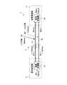
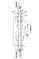
図1は、第1実施形態に係る信号伝送装置の一例を示す概念構成図である。図1に示すように、信号伝送装置1は、単相の入力信号Sinを一対の伝送経路3を介して信号送信部2から信号受信部4に平衡伝送し、単相の出力信号Soutを出力する。 FIG. 1 is a conceptual configuration diagram illustrating an example of a signal transmission device according to the first embodiment. As shown in FIG. 1, the
信号送信部2は差動変換部21を有している。なお、第1実施形態において、差動変換部21は本発明の振幅調節手段の一例である。差動変換部21は、単相の入力信号Sinを互いに逆位相の第1及び第2伝送信号S(+)、S(−)に変換する。一対の伝送経路3は、第1伝送信号S(+)が伝送される第1伝送経路31と、第2伝送信号S(−)が伝送される第2伝送経路32と、を含んで構成されている。また、信号受信部4は単相変換部41を有している。この単相変換部41は、一対の伝送経路3から信号受信部4が受信する第1及び第2伝送信号Sn(+)、Sn(−)を単相の出力信号Soutに変換する。 The
次に、図1を参照し、信号伝送装置1により電気信号が平衡伝送される過程を説明する。なお、ここでは、単相の正弦波信号Sin(=Asinωt)が平衡伝送される様子を一例として説明する。 Next, with reference to FIG. 1, a process in which an electric signal is balanced and transmitted by the
まず、信号送信部2において、差動変換部21は、単相の入力信号Sinを次の数式1及び2を満足するように、一対の伝送信号S(+)、S(−)からなる差動信号に変換する。この変換により、第1伝送信号S(+)(=+Dsinωt)及び第2伝送信号S(−)(=−Esinωt)が生成される。これら第1及び第2伝送信号S(+)、S(−)は、互いに逆位相、且つ、異なる振幅(以下では非対称振幅と呼ぶ)の信号となっている。
E*S(+)+D*S(−)=0 (数式1)
E*S(+)−D*S(−)=Sin (数式2)First, in the
E * S (+) + D * S (−) = 0 (Formula 1)
E * S (+) − D * S (−) = Sin (Formula 2)
ここで、ωは単相の入力信号Sin、第1及び第2伝送信号S(+)、S(−)の角周波数を示し、tは時間を示している。また、A、D及びEは、それぞれ、単相の入力信号Sin、第1及び第2伝送信号S(+)、S(−)の各振幅を示している。なお、数式2によれば、振幅A、D、及びEは次の数式3を満たす。
2DE=A (数式3)Here, ω represents the single-phase input signal Sin, the angular frequencies of the first and second transmission signals S (+) and S (−), and t represents time. A, D, and E indicate the amplitudes of the single-phase input signal Sin and the first and second transmission signals S (+) and S (−), respectively. According to
2DE = A (Formula 3)
また、振幅D及びEは、後述する第1及び第2ノイズ信号N1、N2の振幅B、C(B>C)に応じて設定されている。より具体的には、第1ノイズ信号N1に対する第1伝送信号S(+)の振幅比が第2ノイズ信号N2に対する第2伝送信号S(−)の振幅比と等しくなるように設定される。すなわち、振幅D及びEは次の数式4も満足するように設定される。
E:C=D:B
EB=CD (数式4)The amplitudes D and E are set in accordance with amplitudes B and C (B> C) of first and second noise signals N1 and N2, which will be described later. More specifically, the amplitude ratio of the first transmission signal S (+) to the first noise signal N1 is set to be equal to the amplitude ratio of the second transmission signal S (−) to the second noise signal N2. That is, the amplitudes D and E are set so as to satisfy the following
E: C = D: B
EB = CD (Formula 4)
こうして生成された第1及び第2伝送信号S(+)、S(−)は、信号送信部2から出力され、第1及び第2伝送経路31、32で伝送される。ここで、伝送中に第1及び第2伝送経路31、32が外部ノイズの影響を受けると、第1及び第2伝送信号S(+)、S(−)には同位相の第1及び第2ノイズ信号N1(=+Bsinωat)、N2(=+Csinωat)が重畳される。ここで、B及びCはそれぞれ第1及び第2ノイズ信号N1、N2の振幅を示しており、ωaは第1及び第2ノイズ信号N1、N2の角周波数を示している。 The first and second transmission signals S (+) and S (−) thus generated are output from the
そのため、信号受信部4は、次の数式5及び6に示すような各ノイズ信号が重畳された第1及び第2伝送信号Sn(+)、Sn(−)を第1及び第2伝送経路31、32から受信する。
Sn(+)=S(+)+N1
=+Dsinωt+Bsinωat (数式5)
Sn(−)=S(−)+N2
=−Esinωt+Csinωat (数式6)Therefore, the
Sn (+) = S (+) + N1
= + Dsinωt + Bsinωat (Formula 5)
Sn (-) = S (-) + N2
= −Esinωt + Csinωat (Formula 6)
信号受信部4において、単相変換部41は、各ノイズ信号N1、N2が重畳された第1及び第2伝送信号Sn(+)、Sn(−)を単相の出力信号Soutに変換する。この変換は、次の数式7のように、各ノイズ信号N1、N2が重畳される前の第1及び第2伝送信号S(+)、S(−)の振幅比に基づいて行われる。
Sout=ESn(+)−DSn(−) (数式7)In the
Sout = ESn (+) − DSn (−) (Formula 7)
ここで、差動信号(第1及び第2伝送信号S(+)、S(−))の各振幅は、上述の数式4の条件を満たすように設定されている。従って、単相変換部41が単相の出力信号Soutを生成する際には、次の数式8のように、第1及び第2ノイズ信号N1、N2が除去される。
Sout=E{+Dsinωt+Bsinωat}
−D{−Esinωt+Csinωat}
=2DEsinωt+(EB−CD)sinωat
=Asinωt (数式8)Here, the amplitudes of the differential signals (first and second transmission signals S (+) and S (−)) are set so as to satisfy the condition of the above-described
Sout = E {+ Dsinωt + Bsinωat}
−D {−Esinωt + Csinωat}
= 2DEsinωt + (EB−CD) sinωat
= Asinωt (Formula 8)
さらには、第1及び第2伝送信号S(+)、S(−)に重畳される同位相の第1及び第2ノイズ信号N1、N2は、同振幅であるか非対称振幅(異なる振幅)であるかに拘らず、除去される。従って、信号伝送装置1では、外部ノイズが差動信号に及ぼす影響を回避することができる。 Furthermore, the first and second noise signals N1 and N2 having the same phase superimposed on the first and second transmission signals S (+) and S (−) have the same amplitude or asymmetric amplitude (different amplitudes). It is removed regardless of whether it exists. Therefore, the
なお、以上に説明した構成は、第1及び第2伝送信号S(+)、S(−)に重畳される第1及び第2ノイズ信号N1、N2の振幅B、Cがほぼ変化しない場合に、特に有効である。第1及び第2ノイズ信号N1、N2の振幅B、Cが変化する場合には、信号送信部2における差動信号への変換条件の設定、及び、信号受信部4における単相信号Soutへの変換条件の設定を適宜変更することにより対応可能である。また、第1及び第2ノイズ信号N1、N2の振幅B、Cが上述の数式4を満たす条件から外れていたとしても、単相の出力信号Soutに重畳されるノイズ成分を効果的に低減することは可能である。その場合には、非対称振幅の第1及び第2ノイズ信号N1、N2のうちのより大きい振幅のノイズ信号(たとえば第1ノイズ信号N1)が、非対称振幅の第1及び第2伝送信号S(+)、S(−)のうちのより大きい振幅の伝送信号(たとえば第1伝送信号S(+))に重畳されていればよい。たとえば、第1及び第2ノイズ信号N1、N2の振幅がB>Cである場合には、第1及び第2伝送信号S(+)、S(−)の振幅はD>Eであればよい。
(比較例1)The configuration described above is used when the amplitudes B and C of the first and second noise signals N1 and N2 superimposed on the first and second transmission signals S (+) and S (−) are not substantially changed. Is particularly effective. When the amplitudes B and C of the first and second noise signals N1 and N2 change, the setting of the conversion condition to the differential signal in the
(Comparative Example 1)
次に、本実施形態の信号伝送装置1の効果を理解し易くするための比較例1について説明する。図2は、比較例1に係る信号伝送装置を示す概念構成図である。図2に示すように、比較例1の信号伝送装置100では、入力信号Sinを逆位相且つ同振幅の差動信号に変換して平衡伝送する。 Next, Comparative Example 1 for facilitating understanding of the effect of the
比較例1では、信号送信部102において、差動変換部121は、単相の入力信号Sinを次の数式9を満足するように、一対の伝送信号S(+)、S(−)からなる差動信号に変換する。この変換により、逆位相且つ同振幅の第1伝送信号S(+)(=+(A/2)sinωt)及び第2伝送信号S(−)(=−(A/2)sinωt)が生成される。
S(+)+S(−)=0
S(+)−S(−)=Sin (数式9)In Comparative Example 1, in the
S (+) + S (−) = 0
S (+) − S (−) = Sin (Formula 9)
こうして生成された第1及び第2伝送信号S(+)、S(−)は、信号送信部102から出力される。そして、第1及び第2伝送経路131、132にて、同位相の第1及び第2ノイズ信号N1(=+Bsinωat)、N2(=+Csinωat)が重畳される。 The first and second transmission signals S (+) and S (−) generated in this way are output from the
信号受信部104は、各ノイズ信号N1、N2が重畳された第1及び第2伝送信号Sn(+)、Sn(−)を第1及び第2伝送経路131、132から受信する。単相変換部141が次の数式10のように、各ノイズ信号N1、N2が重畳された第1及び第2伝送信号Sn(+)、Sn(−)を単相の出力信号Soutに変換する。
Sout=Sn(+)−Sn(−)
Sout={+(A/2)sinωt+Bsinωat}
−{−(A/2)sinωt+Csinωat}
=Asinωt+(B−C)sinωat (数式10)The
Sout = Sn (+) − Sn (−)
Sout = {+ (A / 2) sinωt + Bsinωat}
− {− (A / 2) sinωt + Csinωat}
= Asin ωt + (B−C) sin ωat (Formula 10)
ここで、第1及び第2ノイズ信号N1、N2は、同振幅(すなわちB=C)であれば、第1及び第2伝送信号Sn(+)、Sn(−)から除去できるが、非対称振幅(すなわちB≠C)であれば除去できない。従って、比較例1の信号伝送装置100では、振幅の異なるノイズ信号N1、N2が差動信号に及ぼす影響を回避することができない。 Here, the first and second noise signals N1 and N2 can be removed from the first and second transmission signals Sn (+) and Sn (−) if they have the same amplitude (ie, B = C), but the asymmetric amplitude. If (that is, B ≠ C), it cannot be removed. Therefore, in the
以上、本発明の第1実施形態について説明した。第1実施形態によれば、信号伝送装置1は、信号送信部2と、第1伝送経路31と、第2伝送経路32と、信号受信部4と、を備えている。信号送信部2は、互いに逆位相の第1及び第2伝送信号S(+)、S(−)を送信する。第1伝送経路31には第1伝送信号S(+)が伝送され、第2伝送経路32には第2伝送信号S(−)が伝送される。信号受信部4は、第1伝送経路31から受信する第1伝送信号Sn(+)、及び第2伝送経路32から受信する第2伝送信号Sn(−)を単相の出力信号Soutに変換する。また、信号受信部4に受信される第1及び第2伝送信号S(+)、S(−)の各振幅を相違させる差動変換部21(振幅調節手段)が信号送信部2に設けられている。信号受信部4は、差動変換部21にて調節された第1及び第2伝送信号S(+)、S(−)の振幅比に基づいて、受信した第1及び第2伝送信号Sn(+)、Sn(−)を変換する。 The first embodiment of the present invention has been described above. According to the first embodiment, the
また、第1実施形態によれば、信号伝送方法が以下のステップを備える。一のステップでは、互いに逆位相の第1及び第2伝送信号S(+)、S(−)を送信する。一のステップでは、第1及び第2伝送信号S(+)、S(−)を伝送する。一のステップでは、伝送するステップにて伝送された第1及び第2伝送信号Sn(+)、Sn(−)を単相の出力信号Soutに変換する。また、前述の送信するステップが、前述の伝送するステップにて伝送される第1及び第2伝送信号S(+)、S(−)の各振幅を相違させるステップを含む。そして、前述の変換するステップにおいて、前述の相違させるステップにて調節された第1及び第2伝送信号S(+)、S(−)の振幅比に基づいて、前述の伝送するステップにて伝送された第1及び第2伝送信号Sn(+)、Sn(−)を変換する。 According to the first embodiment, the signal transmission method includes the following steps. In one step, first and second transmission signals S (+) and S (−) having opposite phases are transmitted. In one step, the first and second transmission signals S (+) and S (−) are transmitted. In one step, the first and second transmission signals Sn (+) and Sn (−) transmitted in the transmitting step are converted into a single-phase output signal Sout. Further, the transmitting step includes a step of making the amplitudes of the first and second transmission signals S (+) and S (−) transmitted in the transmitting step differ from each other. In the converting step, transmission is performed in the transmitting step based on the amplitude ratio of the first and second transmission signals S (+) and S (−) adjusted in the different step. The first and second transmission signals Sn (+) and Sn (−) thus converted are converted.
こうすれば、相違する振幅に調整された互いに逆位相の第1及び第2伝送信号S(+)、S(−)が伝送される。そして、差動変換部21にて調節された第1及び第2伝送信号S(+)、S(−)の振幅比に基づいて、伝送された第1及び第2伝送信号Sn(+)、Sn(−)が単相の出力信号Soutに変換される。そのため、第1及び第2伝送信号S(+)、S(−)の伝送中に振幅の異なるノイズ信号N1、N2が重畳されても、第1及び第2伝送信号Sn(+)、Sn(−)が単相の出力信号Soutに変換される際、ノイズ信号N1、N2の影響を低減することができる。従って、振幅の異なるノイズ信号N1、N2が差動信号に及ぼす影響を効果的に低減することができる。 In this way, the first and second transmission signals S (+) and S (−) having opposite phases and adjusted to have different amplitudes are transmitted. Then, based on the amplitude ratio of the first and second transmission signals S (+) and S (−) adjusted by the
また、第1実施形態の信号伝送装置1では、差動変換部21は、第1ノイズ信号N1が重畳される前の第1伝送信号S(+)の第1ノイズ信号N1に対する振幅比(D:B)は、第2ノイズ信号N2が重畳される前の第2伝送信号S(−)の第2ノイズ信号N2に対する振幅比(E:C)と等しくする。こうすれば、第1及び第2伝送信号Sn(+)、Sn(−)が単相の出力信号Soutに変換される際、第1及び第2ノイズ信号N1、N2をほぼ完全に除去することができる。従って、振幅の異なるノイズ信号N1、N2が差動信号に及ぼす影響を回避することができる。
<第1実施形態の変形例>Further, in the
<Modification of First Embodiment>
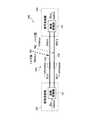
なお、上述の第1実施形態では、差動変換部21は、単相の入力信号Sinから差動信号への変換する機能と、差動信号の各振幅D、Eを調整する機能の両方を担っているが、各機能毎に構成部を設けるようにしてもよい。図3は、第1実施形態の変形例に係る信号伝送装置の一例を示す概念構成図である。 In the first embodiment described above, the
図3に示すように、信号伝送装置1の信号送信部2は、送信信号振幅調整部22をさらに有している。なお、第1実施形態の変形例において、送信信号振幅調整部22は本発明の振幅調節手段の一例である。 As shown in FIG. 3, the
差動変換部21は、単相の入力信号Sinを互いに逆位相且つ同振幅の第1及び第2伝送信号Sa(+)、Sa(−)に変換する。送信信号振幅調整部22は、第1及び第2送信信号振幅調整部22a、22bを含んで構成されている。第1送信信号振幅調整部22aは、差動変換部21で生成された第1伝送信号Sa(+)の振幅を、数式4の条件を満たす振幅Dに調整する。また、第2送信信号振幅調整部22bは、差動変換部21で生成された第2伝送信号Sa(−)の振幅を、数式4の条件を満たす振幅Eに調整する。 The
また、信号受信部4は、受信信号振幅調整部42をさらに有している。受信信号振幅調整部42は、第1及び第2受信信号振幅調整部42a、42bを含んで構成されている。第1受信信号振幅調整部42aは、第1ノイズ信号N1が重畳された第1伝送信号Sn(+)の振幅をE倍に調整する。また、第2受信信号振幅調整部42bは、第2ノイズ信号N2が重畳された第2伝送信号Sn(−)の振幅をD倍に調整する。単相変換部41は、調整された第1及び第2伝送信号ESn(+)、DSn(−)を次の数式11のように演算することにより、単相の出力信号Soutに変換する。
Sout=ESn(+)−DSn(−)
=E{+Dsinωt+Bsinωat}
−D{−Esinωt+Csinωat}
=2DEsinωt+(EB−CD)sinωat
=Asinωt (数式11)
The
Sout = ESn (+) − DSn (−)
= E {+ Dsinωt + Bsinωat}
−D {−Esinωt + Csinωat}
= 2DEsinωt + (EB−CD) sinωat
= Asinωt (Formula 11)
なお、図3では、信号送信部2の送信信号振幅調整部22は第1及び第2伝送信号S(+)、S(−)の各振幅をD及びEに調整しているが、たとえば1及び(E/D)、又は、(D/E)及び1に調整してもよい。ただし、このように調整される場合、信号受信部4の受信信号振幅調整部42は第1及び第2伝送信号Sn(+)、Sn(−)の各振幅を、たとえば(E/D)倍及び1倍、又は、1倍及び(D/E)倍に調整すればよい。 In FIG. 3, the transmission signal
以上、本発明の第1実施形態の変形例について説明した。この変形例の信号伝送装置1によれば、信号送信部2は、差動変換部21と、送信信号振幅調整部22と、を有する。差動変換部21は、単相の入力信号Sinを互いに逆位相の第1及び第2伝送信号Sa(+)、Sa(−)に変換する。送信信号振幅調整部22は、第1伝送信号S(+)の振幅Dが第2伝送信号S(−)の振幅Eと異なるように第1及び第2伝送信号S(+)、S(−)の各振幅D、Eを調整する。また、信号受信部4は、受信信号振幅調整部42と、単相変換部41と、を有する。受信信号振幅調整部42は、該信号受信部4に受信される第1及び第2伝送信号Sn(+)、Sn(−)の各振幅を、送信信号振幅調整部22により調整された第1及び第2伝送信号S(+)、S(−)の振幅比に基づいて調整する。単相変換部41は、受信信号振幅調整部42により調整された第1及び第2伝送信号Sb(+)、Sb(−)を単相の出力信号Soutに変換する。 In the above, the modification of 1st Embodiment of this invention was demonstrated. According to the
こうすれば、互いに逆位相且つ異なる振幅の第1及び第2伝送信号S(+)、S(−)を信号送信部2から送信することができる。また、第1及び第2伝送信号S(+)、S(−)に振幅の異なるノイズ信号N1、N2が重畳されても、送信信号振幅調整部22により調整された第1及び第2伝送信号S(+)、S(−)の振幅比に基づいて調整することにより、単相の出力信号Soutへの変換を容易に行うことができる。 Thus, the first and second transmission signals S (+) and S (−) having opposite phases and different amplitudes can be transmitted from the
また、上述の第1実施形態では、信号送信部2から逆位相且つ非対称振幅の差動信号が出力される場合に、外部ノイズが1対の伝送経路3を伝送する差動信号に及ぼす影響を回避する構成について説明した。次には、信号送信部2から逆位相且つ同振幅の差動信号が出力される場合にも外部ノイズの影響を回避することができる構成について説明する。
<第2実施形態>Further, in the above-described first embodiment, when a differential signal having an opposite phase and asymmetric amplitude is output from the
Second Embodiment
第2実施形態について説明する。第2実施形態では、差動信号が伝送される一対の伝送経路3の各インピーダンスZ1、Z2を相違させることにより、信号受信部4に逆位相且つ非対称振幅の差動信号を受信させている。すなわち、第2実施形態において、一対の伝送経路3は本発明の振幅調節手段の一例となっている。以下では、第2実施形態について、第1実施形態と異なる事項について説明する。また、第1実施形態と同じ構成には同じ符号を付し、その説明を省略することがある。 A second embodiment will be described. In the second embodiment, by making the impedances Z1 and Z2 of the pair of
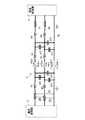
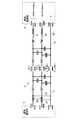
まず、理想的な平衡伝送では、差動信号を一対の伝送経路3で伝送させているが、実際には、伝送経路3はたとえばグランドパターンや他の信号線路との電気的な結合も無視できない。そのため、実際の平衡伝送では、ある程度の不平衡伝送成分を含んでいる。図4は、実際の不平衡伝送成分を考慮した伝送経路の等価回路図である。 First, in an ideal balanced transmission, a differential signal is transmitted through a pair of
図4の伝送経路3は、第1及び第2伝送経路31、32のほか、接地された基準経路33を含んで構成されている。また、図4において、斜線でハッチングした四角形は第1及び第2伝送経路31、32の太さを示しており、各伝送経路31、32のインピーダンスZ1、Z2を表している。また、ΔL及びΔCは線路の微小区間におけるインダクタおよ
びキャパシタであり、各伝送経路31、32のインピーダンスZ1、Z2のインダクタンス成分及びキャパシタンス成分を表している。The
第1及び第2伝送経路31、32には互いに逆位相の第1及び第2伝送信号S(+)、S(−)が入力され、信号送信部2から信号受信部4に伝送される。また、信号受信部4から各経路31〜33には第1及び第2伝送信号S(+)、S(−)の帰還信号が出力されるが、各帰還電流の一部は基準経路33に流れる。たとえば、第1伝送信号+S(+)の帰還電流−S(+)の一部−αS(+)(0<α<1)は第2伝送経路32を流れるが、残りの一部−(1−α)S(+)は基準経路33を流れる。また、第2伝送信号+S(−)の帰還電流−S(−)の一部−βS(−)(0<β<1)は第1伝送経路31を流れるが、残りの一部−(1−β)S(−)は基準経路33を流れる。α及びβは、第1及び第2伝送経路31、32の各インピーダンスZ1、Z2が同じである場合にはα=βとなるが、各インピーダンスZ1、Z2が異なる場合にはα≠βとなる。
First and second transmission signals S (+) and S (−) having opposite phases to each other are input to the first and
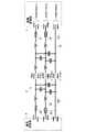
まず、第1及び第2伝送経路31、32の各インピーダンスZ1、Z2がほぼ同じである場合について説明する。図5Aは、インピーダンスに差異のない伝送経路に逆位相且つ同振幅の差動信号を伝送させた場合の等価回路図である。また、図5Bは、インピーダンスに差異のない伝送経路に逆位相且つ異なる振幅の差動信号を伝送させた場合の等価回路図である。なお、ここでは、第1及び第2伝送経路31、32の各インピーダンスZ1、Z2の作用が差動信号に及ぼす作用を理解し易くするために、第1及び第2ノイズ信号N1、N2の重畳については省略して説明する。 First, a case where the impedances Z1 and Z2 of the first and
伝送経路3に逆位相且つ同振幅の第1及び第2伝送信号S(+)(=+(A/2)sinωt)、S(−)(=−(A/2)sinωt)が伝送される場合、図5Aに示すように、信号受信部4が受信する第1伝送信号Sn(+)は+(A/2)(1+α)sinωtとなり、第2伝送信号Sn(−)は−(A/2)(1+α)sinωtとなる。すなわち、信号受信部4は逆位相且つ同振幅の差動信号を受信する。 First and second transmission signals S (+) (= + (A / 2) sin ωt) and S (−) (= − (A / 2) sin ωt) having opposite phases and the same amplitude are transmitted to the
一方、伝送経路3に逆位相且つ異なる振幅の第1及び第2伝送信号S(+)(=+Dsinωt)、S(−)(=−Esinωt)が伝送される場合、図5Bに示すように、信号受信部4が受信する第1伝送信号Sn(+)は+(D+αE)sinωtとなり、第2伝送信号Sn(−)は−(αD+E)sinωtとなる。すなわち、信号受信部4は逆位相且つ異なる振幅の差動信号を受信する。
On the other hand, the first and second transmission signals S of the opposite phase and different amplitudes to the transmission path 3 (+) (= + Dsinωt ), S (-) -If (= E sin .omega.t) is transmitted, as shown in FIG. 5B The first transmission signal Sn (+) received by the
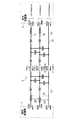
次に、第1及び第2伝送経路31、32の各インピーダンスZ1,Z2が異なる場合について説明する。図6は、各インピーダンスが異なる伝送経路に逆位相且つ同振幅の差動信号を伝送させた場合の等価回路図である。なお、ここでも、第1及び第2伝送経路31、32の各インピーダンスZ1、Z2の作用が差動信号に及ぼす作用を理解し易くするために、第1及び第2ノイズ信号N1、N2の重畳については省略して説明する。 Next, the case where the impedances Z1 and Z2 of the first and
伝送経路3に逆位相且つ同振幅の第1及び第2伝送信号S(+)(=+(A/2)sinωt)、S(−)(=−(A/2)sinωt)が伝送される場合、図6に示すように、信号受信部4が受信する第1伝送信号Sn(+)は+(A/2)(1+β)sinωtとなり、第2伝送信号Sn(−)は−(A/2)(1+α)sinωtとなる。すなわち、信号送信部2から逆位相且つ同振幅の差動信号が伝送されたとしても、信号受信部4は逆位相且つ異なる振幅の差動信号を受信する。 First and second transmission signals S (+) (= + (A / 2) sin ωt) and S (−) (= − (A / 2) sin ωt) having opposite phases and the same amplitude are transmitted to the
このような伝送経路3は、第1及び第2伝送経路31、32の各インピーダンスZ1、Z2のうちの抵抗成分、容量成分、及びインダクタンス成分のうちの少なくともいずれかを相違させることにより実現可能である。以下に、インピーダンスZ1、Z2の異なる伝送経路3の具体的な構成例について、第1〜第6実施例を挙げて説明する。
(第1実施例)Such a
(First embodiment)
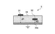
図7Aは、第2実施形態の伝送経路の一例を示す図である。図7Aの伝送経路3では、接地された導体基板33a上に誘電体層34が形成されている。また、誘電体層34の上面には断面積の異なる第1及び第2伝送経路31、32が配置されている。こうすれば、第1及び第2伝送経路31、32のインピーダンスZ1、Z2の各容量成分を相違させることができる。なお、第1実施例において、導体基板33aは本発明の接地部の一部である。
(第2実施例)FIG. 7A is a diagram illustrating an example of a transmission path according to the second embodiment. In the
(Second embodiment)
図7Bは、第2実施形態の伝送経路の他の一例を示す図である。図7Bの伝送経路3では、接地された導体基板33a上に誘電体層34が形成されている。また、第1伝送経路31は誘電体層34上に配置されているが、第2伝送経路32は誘電体層34の内部に配置される。こうすれば、第1及び第2伝送経路31、32と導体基板33aとの各間隔d1、d2が相違するため、第1及び第2伝送経路31、32のインピーダンスZ1、Z2の各容量成分を相違させることができる。なお、第2実施例において、導体基板33aは本発明の接地部の一部である。
(第3実施例)FIG. 7B is a diagram illustrating another example of the transmission path according to the second embodiment. In the
(Third embodiment)
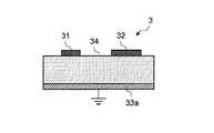
図7Cは、第2実施形態の伝送経路の他の一例を示す図である。図7Cの伝送経路3では、誘電体層34の上面には第1及び第2伝送経路31、32が配置されている。また、誘電体層34の下面の一部に接地された導体基板33aが設けられている。導体基板33aの主面の法線方向から見た平面視において、第1伝送経路31は導体基板33aと重なっているが、第2伝送経路32は導体基板33aと重なっていない。このようにしても、第1及び第2伝送経路31、32と導体基板33aとの各間隔d1、d2を容易に相違させることができるため、第1及び第2伝送経路31、32のインピーダンスZ1、Z2の各容量成分を相違させることができる。なお、第3実施例において、導体基板33aは本発明の接地部の一部である。
(第4実施例)FIG. 7C is a diagram illustrating another example of the transmission path according to the second embodiment. In the
(Fourth embodiment)
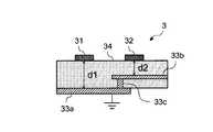
図7Dは、第2実施形態の伝送経路の他の一例を示す図である。図7Dの伝送経路3では、誘電体層34の上面には第1及び第2伝送経路31、32が配置されている。また、誘電体層34の下面の一部に接地された導体基板33aが設けられている。また、誘電体層34の内部には導体層33bが設けられている。この導体層33bは、内部に導通経路が形成されたビア33cを介して導体基板33aと導通している。また、導体基板33aの主面の法線方向から見た平面視において、第1伝送経路31は導体層33bと重なっていないが、第2伝送経路32は導体層33bと重なっている。このようにしても、第1伝送経路31及び導体基板33aの間隔d1と、第2伝送経路32及び導体層33bの間隔d2とを容易に相違させることができるため、第1及び第2伝送経路31、32のインピーダンスZ1、Z2の各容量成分を相違させることができる。なお、第4実施例において、導体基板33a、導体層33b、及びビア33cは本発明の接地部の一部である。
(第5実施例)FIG. 7D is a diagram illustrating another example of the transmission path according to the second embodiment. In the
(5th Example)
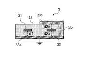
図7Eは、第2実施形態の伝送経路の他の一例を示す図である。図7Eの伝送経路3では、接地された導体基板33a上に誘電体層34が形成されている。また、誘電体層34の内部には第1及び第2伝送経路31、32が配置されている。さらに、誘電体層34の上面の一部には導体層33bが設けられており、この導体層33bは、内部に導通経路が形成されたビア33cを介して導体基板33aと導通している。また、導体基板33aの主面の法線方向から見た平面視において、第1伝送経路31は導体層33bと重なっていないが、第2伝送経路32は導体層33bと重なっている。そのため、第2伝送経路32は、誘電体層34の内部において、導体基板33a及び導体層33bの間に配置されている。こうすれば、誘電体層34の内部に配置される第2伝送経路32は、導体基板33aとの間d2a及び導体層33bとの間d2bに2つの容量成分を形成することができるため、第1及び第2伝送経路31、32のインピーダンスZ1、Z2の各容量成分を相違させることができる。なお、第5実施例において、導体基板33a、導体層33b、及びビア33cは本発明の接地部の一部である。
(第6実施例)FIG. 7E is a diagram illustrating another example of the transmission path of the second embodiment. In the
(Sixth embodiment)
図7Fは、第2実施形態の伝送経路の他の一例を示す図である。図7Fの伝送経路3では、接地された導体基板33a上に、誘電率の異なる2つの誘電体層34a、34bが形成されている。また、一方の誘電体層34aの上面には第1伝送経路31が配置され、他方の誘電体層34bの上面には第2伝送経路32が配置されている。第1及び第2伝送経路31、32と導体基板33aとの間の各静電容量ε1、ε2が異なるため、第1及び第2伝送経路31、32のインピーダンスZ1、Z2の各容量成分を相違させることができる。なお、第6実施例において、導体基板33aは本発明の接地部の一部である。 FIG. 7F is a diagram illustrating another example of the transmission path according to the second embodiment. In the
なお、伝送経路3の構成例は、以上に説明した第1〜第6実施例に限らない。たとえば、第2〜第6実施例において第1及び第2伝送経路31、32の各断面積を相違させてもよい。こうすれば、第1及び第2伝送経路31、32のインピーダンスZ1、Z2の各容量成分をさらに相違させることができる。 The configuration example of the
以上、第2実施形態について説明した。第2実施形態の信号伝送装置1は、信号送信部2と、第1伝送経路31と、第2伝送経路32と、信号受信部4と、を備える。信号送信部2は互いに逆位相の第1及び第2伝送信号S(+)、S(−)を送信する。第1伝送経路31には第1伝送信号S(+)が伝送され、第2伝送経路32には第2伝送信号S(−)が伝送される。信号受信部4は、第1伝送経路31から受信する第1伝送信号Sn(+)、及び第2伝送経路32から受信する第2伝送信号Sn(−)を単相の出力信号Soutに変換する。また、第1及び第2伝送経路31、32は、(互いにインピーダンスZ1、Z2が異なるため、)信号受信部4に受信される第1及び第2伝送信号Sn(+)、Sn(−)の各振幅を相違させる振幅調節手段として機能する。そして、信号受信部4は、振幅調節手段にて調節される第1及び第2伝送信号S(+)、S(−)の振幅比に基づいて、受信した第1及び第2伝送信号Sn(+)、Sn(−)を変換する。 The second embodiment has been described above. The
こうすれば、相違する振幅に調整された互いに逆位相の第1及び第2伝送信号S(+)、S(−)が伝送される。そして、振幅調節手段として機能する第1及び第2伝送経路31、32にて調節された第1及び第2伝送信号S(+)、S(−)の振幅比に基づいて、伝送された第1及び第2伝送信号Sn(+)、Sn(−)が単相の出力信号Soutに変換される。そのため、第1及び第2伝送信号S(+)、S(−)の伝送中に振幅の異なるノイズ信号N1、N2が重畳されても、第1及び第2伝送信号Sn(+)、Sn(−)が単相の出力信号Soutに変換される際、ノイズ信号N1、N2の影響を低減することができる。従って、振幅の異なるノイズ信号N1、N2が差動信号に及ぼす影響を効果的に低減することができる。 In this way, the first and second transmission signals S (+) and S (−) having opposite phases and adjusted to have different amplitudes are transmitted. The first and second transmission signals S (+) and S (−) adjusted by the first and
また、第2実施形態の信号伝送装置1によれば、第1伝送経路31のインピーダンスZ1は第2伝送経路32のインピーダンスZ2と異なる。そのため、信号送信部2から出力される第1及び第2伝送信号S(+)、S(−)の振幅は同じであっても、信号受信部4に受信される第1及び第2伝送信号Sn(+)、Sn(−)の振幅を相違させることができる。従って、第1及び第2伝送信号Sn(+)、Sn(−)が単相の出力信号Soutに変換される際、振幅の異なるノイズ信号N1、N2の影響を十分に低減することができる。 Further, according to the
第1及び第2伝送経路31、32の各インピーダンスZ1、Z2を相違させる方法としては、以下の例を挙げることができる。たとえば、第2実施形態において、第1及び第2伝送経路31、32の断面積が異なっていてもよい。こうすれば、第1及び第2伝送経路31、32のインピーダンスZ1、Z2の容量成分を相違させることができる。 The following example can be given as a method of making the impedances Z1 and Z2 of the first and
また、第2実施形態において、信号伝送装置1が、第1及び第2伝送経路31、32が配置される誘電体層34と、誘電体層34が設けられる接地部と、をさらに備えていてもよい。そして、接地部は接地された導電基板33aを有し、第1伝送経路31及び接地部間の最短距離は、第2伝送経路32及び接地部間の最短距離と異なっていてもよい。こうすれば、第1及び第2伝送経路31、32のインピーダンスZ1、Z2の容量成分を相違させることができる。 In the second embodiment, the
さらに、誘電体層34は誘電率の異なる第1及び第2誘電体層34a、34bを有し、第1伝送経路31は第1誘電体層34aに設けられ、第2伝送経路32は第2誘電体層34bに設けられてもよい。こうすれば、第1及び第2伝送経路31、32はそれぞれ誘電率の異なる誘電体層34a、34bに設けられるので、第1及び第2伝送経路31、32のインピーダンスZ1、Z2の容量成分を相違させることができる。 Furthermore, the
或いは、第2実施形態において、誘電率の異なる第1及び第2誘電体層を有する誘電体層と、誘電体層が設けられる接地部と、をさらに備えていてもよい。そして、接地部は接地された導体基板を有し、第1伝送経路は第1誘電体層に設けられ、第2伝送経路は第2誘電体層に設けられてもよい。このようにしても、第1及び第2伝送経路31、32はそれぞれ誘電率の異なる誘電体層34a、34bに設けられるので、第1及び第2伝送経路31、32のインピーダンスZ1、Z2の容量成分を相違させることができる。 Alternatively, the second embodiment may further include a dielectric layer having first and second dielectric layers having different dielectric constants, and a ground portion provided with the dielectric layer. The ground unit may include a grounded conductor substrate, the first transmission path may be provided in the first dielectric layer, and the second transmission path may be provided in the second dielectric layer. Even in this case, since the first and
また、第2実施形態において、接地部は、導体基板33aと電気的に接続される導体層33bをさらに有していてもよい。また、導体層33bは、導体基板33aの主面の法線方向から見た平面視において、第2伝送経路32と重なるように、誘電体層34に設けられていてもよい。こうすれば、平面視において第2伝送経路32と重なるように、導体層33bを誘電体層34に設けることにより、第1及び第2伝送経路31、32のインピーダンスZ1、Z2の容量成分を相違させることができる。 In the second embodiment, the ground portion may further include a
さらに、導体基板33aと電気的に接続される導体層33bは誘電体層34上に設けられ、第2伝送経路32は、誘電体層34の内部且つ導体基板33a及び導体層33bの間に配置されてもよい。こうすれば、誘電体層34の内部に配置される第2伝送経路32は、導体基板33aとの間及び導体層33bとの間に2つの容量を形成することができ、第1及び第2伝送経路31、32のインピーダンスZ1、Z2の容量成分を相違させることができる。
<第3実施形態>Furthermore, the
<Third Embodiment>
次に、第3実施形態について説明する。第3実施形態では、第1伝送経路31を伝送する第1伝送信号S(+)の振幅と、第2伝送経路32を伝送する第2伝送信号S(−)の振幅とが、独立して制御される。以下では、第3実施形態について、第1及び第2実施形態と異なる事項について説明する。また、第1及び第2実施形態と同じ構成には同じ符号を付し、その説明を省略することがある。 Next, a third embodiment will be described. In the third embodiment, the amplitude of the first transmission signal S (+) transmitted through the
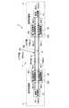
図8は、第3実施形態に係る信号伝送装置の一例を示す概念構成図である。図8に示すように、信号受信部4は、信号受信部4が受信する第1及び第2伝送信号Sn(+)、Sn(−)の振幅を検出する検波部43をさらに有している。この検波部43は、第1及び第2ディテクタ43a、43bを含んで構成されている。第1及び第2ディテクタ43a、43bは、それぞれ、信号受信部4が受信する第1及び第2伝送信号Sn(+)、Sn(−)の振幅を検出する第1及び第2検波部である。 FIG. 8 is a conceptual configuration diagram illustrating an example of a signal transmission device according to the third embodiment. As shown in FIG. 8, the
また、信号送信部2の送信信号振幅調整部22は、第1伝送信号S(+)の振幅が第2伝送信号S(−)の振幅と異なるように第1及び第2伝送信号S(+)、S(−)の各振幅D、Eを調整する機能を有する。さらに、送信信号振幅調整部22は、GCA(Gain Control AmplifierまたはGain Control Attenuator)としての機能も有している。送信信号振幅調整部22は、信号送信部2から出力される第1及び第2伝送信号S(+)、S(−)の各振幅D、Eを検波部43の検出結果に基づいてフィードバック制御している。たとえば、第1及び第2送信信号振幅調整部22a、22bは、それぞれ、差動変換部21で生成された第1及び第2伝送信号Sa(+)、Sa(−)の各振幅を上述の数式4の条件を満たす振幅D、Eに調整する。さらに、第1送信信号振幅調整部22aは、第1ディテクタ43aの検出結果に基づいて、信号送信部2から出力される第1伝送信号S(+)の振幅Dをフィードバック制御している。また、第2送信信号振幅調整部22bは、第2ディテクタ43bの検出結果に基づいて、信号送信部2から出力される第2伝送信号S(−)の振幅Eをフィードバック制御している。 In addition, the transmission signal
また、信号受信部4の受信信号振幅調整部42は、検波部43の検出結果に基づいて、各ノイズ信号N1、N2が重畳された第1及び第2伝送信号Sn(+)、Sn(−)の振幅を調整する。たとえば、第1受信信号振幅調整部42aは、第1ディテクタ43aの検出結果に基づいて、第1ノイズ信号N1が重畳された第1伝送信号Sn(+)の振幅を(A/2D)倍に調整する。また、第2受信信号振幅調整部42bは、第2ディテクタ43bの検出結果に基づいて、第2ノイズ信号N2が重畳された第2伝送信号Sn(−)の振幅を(A/2E)倍に調整する。 Further, the received signal
このように、第3実施形態では、第1及び第2ディテクタ43a、43bの検出結果に基づいて、第1及び第2伝送信号S(+)、S(−)が独立にAGC(Automatic Gain Control)制御されている。 Thus, in the third embodiment, based on the detection results of the first and
単相変換部41は、受信信号振幅調整部42にて調整された第1及び第2伝送信号(A/2D)Sn(+)、(A/2E)Sn(−)を次の数式12のように演算することにより、単相の出力信号Soutに変換する。
Sout=(A/2D)Sn(+)−(A/2E)Sn(−) (数式12)The single-
Sout = (A / 2D) Sn (+)-(A / 2E) Sn (-) (Formula 12)
ここで、差動信号(第1及び第2伝送信号S(+)、S(−))の各振幅は、上述の数式4の条件を満たすように設定されている。従って、単相変換部41が単相の出力信号Soutを生成する際には、次の数式13のように、ノイズ成分が除去される。
Sout={+(A/2)sinωt+(BA/2D)sinωat}
−{−(A/2)sinωt+(CA/2E)sinωat}
=Asinωt+(A/2DE)(EB−CD)sinωat
=Asinωt (数式13)Here, the amplitudes of the differential signals (first and second transmission signals S (+) and S (−)) are set so as to satisfy the condition of the above-described
Sout= { + (A / 2) sinωt + (BA / 2D) sinωat}
− {− (A / 2) sinωt + (CA / 2E) sinωat}
= Asinωt + (A / 2DE) (EB−CD) sinωat
= Asinωt (Formula 13)
さらには、第1及び第2伝送信号Sn(+)、Sn(−)に重畳されている同位相の第1及び第2ノイズ信号N1、N2は、同振幅であるか非対称振幅(異なる振幅)であるかに拘らず、除去される。従って、信号伝送装置1では、外部ノイズが差動信号に及ぼす影響を回避することができる。 Furthermore, the first and second noise signals N1 and N2 having the same phase superimposed on the first and second transmission signals Sn (+) and Sn (−) have the same amplitude or asymmetric amplitude (different amplitudes). It is removed regardless of whether or not. Therefore, the
なお、上述の説明では、第1及び第2伝送信号S(+)、S(−)が独立したAGC制御される例を説明したが、本発明の適用範囲はこの例示に限定されない。第1及び第2伝送信号S(+)、S(−)のうちの一方がAGC制御され、他方はAGC Balance制御(一方のAGC制御に対するゲイン差分を制御)してもよい。 In the above description, the example in which the first and second transmission signals S (+) and S (−) are independently AGC-controlled has been described, but the scope of application of the present invention is not limited to this example. One of the first and second transmission signals S (+) and S (−) may be AGC controlled, and the other may be AGC Balanced control (a gain difference with respect to one AGC control is controlled).
以上、第3実施形態について説明した。第3実施形態の信号伝送装置1によれば、信号受信部4が、該信号受信部4が受信する第1及び第2伝送信号Sn(+)、Sn(−)の振幅を検出する検波部43をさらに有している。信号送信部2の送信信号振幅調整部22は、検波部43の検出結果に基づいて、第1及び第2伝送信号S(+)、S(−)の各振幅を独立して調整する。信号受信部4の受信信号振幅調整部42は、検波部43の検出結果に基づいて、信号受信部4に受信される第1及び第2伝送信号Sn(+)、Sn(−)の各振幅を独立して調整する。 The third embodiment has been described above. According to the
こうすれば、フィードバック制御される第1及び第2伝送信号S(+)、S(−)の振幅を独立して調整することができる。従って、第1及び第2伝送信号S(+)、S(−)がフィードバック制御されていても、伝送経路3で伝送される第1及び第2伝送信号S(+)、S(−)の振幅を相違させて、振幅の異なるノイズ信号N1、N2が出力信号Soutに及ぼす影響を十分に低減することができる。
<第4実施形態>In this way, the amplitudes of the first and second transmission signals S (+) and S (−) that are feedback-controlled can be adjusted independently. Therefore, even if the first and second transmission signals S (+) and S (−) are feedback-controlled, the first and second transmission signals S (+) and S (−) transmitted through the
<Fourth embodiment>
上述の第1〜第3実施形態では、外部ノイズの影響を低減することについて説明しているが、外部から受けるノイズの影響と、外部に与えるノイズの影響とは表裏一体に考えることができる。そのため、第1及び第2伝送信号S(+)、S(−)を伝送する逆位相の差動信号(第1及び第2伝送信号)から外部に放射されるノイズ(たとえば電磁波ノイズ)を緩和する手段として、上述の第1〜第3実施形態を適用することもできる。 In the first to third embodiments described above, reduction of the influence of external noise has been described. However, the influence of noise received from the outside and the influence of noise given to the outside can be considered together. Therefore, the noise (for example, electromagnetic wave noise) radiated to the outside from the differential signals (first and second transmission signals) having opposite phases for transmitting the first and second transmission signals S (+) and S (−) are reduced. As the means for performing the above, the first to third embodiments described above can be applied.
また、図9は、信号伝送装置から外部に放射される電磁波ノイズが緩和されることを説明するための概念構成図である。図9において、外部回路Aに近い側の第2伝送経路32を伝送する第2伝送信号S(−)の振幅Eを、遠い側の第1伝送経路31を伝送する第1伝送信号S(+)の振幅Dよりも低く設定する。こうすれば、各伝送経路3から外部回路に放射される電磁波(すなわちノイズ)の振幅差を低減又はなくすことができる。 FIG. 9 is a conceptual configuration diagram for explaining that electromagnetic noise radiated to the outside from the signal transmission device is alleviated. In FIG. 9, the amplitude E of the second transmission signal S (−) transmitted through the
なお、図9では、第3実施形態の信号伝送装置1を例に挙げて説明しているが、第1実施形態の信号伝送装置1、第2実施形態の伝送経路3を用いても同様に、外部に放射される電磁波ノイズを緩和できることはいうまでもない。 In FIG. 9, the
以上、本発明の実施形態について説明した。なお、上述の実施形態は例示であり、その各構成要素や各処理の組み合わせに色々な変形が可能であり、本発明の範囲にあることは当業者に理解されるところである。 The embodiment of the present invention has been described above. Note that the above-described embodiment is an exemplification, and various modifications can be made to each component and combination of processes, and it will be understood by those skilled in the art that they are within the scope of the present invention.
1 信号伝送装置
2 信号送信部
21 差動変換部
22 送信信号振幅調整部
3 伝送経路
31 第1伝送経路
32 第2伝送経路
33 基準経路
33a 導体基板
33b 導体層
33c ビア
34 誘電体層
4 信号受信部
41 単相変換部
42 受信信号振幅調整部
43 検波部DESCRIPTION OF
Claims (12)
Translated fromJapanese第1伝送信号が伝送される第1伝送経路と、
第2伝送信号が伝送される第2伝送経路と、
第1伝送経路から受信する伝送信号、及び第2伝送経路から受信する伝送信号を単相の出力信号に変換する信号受信部と、
を備え、
前記信号受信部に受信される伝送信号の各振幅を相違させる振幅調節手段が、前記信号送信部と第1及び第2伝送経路との少なくとも一方に設けられ、
前記信号受信部は、前記振幅調節手段にて調節された第1及び第2伝送信号の振幅比に基づいて、受信した伝送信号を変換し、
前記振幅調節手段は、第1伝送経路に重畳される第1信号の振幅が第2伝送経路に重畳される第2信号の振幅よりも大きい場合、第1伝送信号の振幅を第2伝送信号の振幅よりも大きくすることを特徴とする信号伝送装置。A signal transmission unit for transmitting the first and second transmission signals having opposite phases to each other;
A first transmission path through which the first transmission signal is transmitted;
A second transmission path through which the second transmission signal is transmitted;
A signal receiving unit for convertingheat transmission signalthat will receive the first transmission path, and theheat transmission signalyou received from the second transmission path on the output signal of the single-phase,
With
Amplitude adjusting means for different respective amplitudes ofheat transmission signalthat will be received by the signal receiving unit is provided on at least one of said signal transmitting portion and the first and second transmission paths,
The signal receiving unit, based on the amplitude ratio of the first and second transmission signals adjusted by said amplitude adjusting meansconverts theheat transmission signalreceived,
When the amplitude of the first signal superimposed on the first transmission path is larger than the amplitude of the second signal superimposed on the second transmission path, the amplitude adjusting unit may change the amplitude of the first transmission signal of the second transmission signal. A signal transmission device characterizedby beinglarger than the amplitude .
前記信号受信部が、該信号受信部に受信される第1及び第2伝送信号の各振幅を、前記送信信号振幅調整部により調整された第1及び第2伝送信号の振幅比に基づいて調整する受信信号振幅調整部と、前記受信信号振幅調整部により調整された第1及び第2伝送信号を前記単相の出力信号に変換する単相変換部と、を有することを特徴とする請求項1に記載の信号伝送装置。The signal transmission unit converts the single-phase input signal into first and second transmission signals having opposite phases, and the first transmission signal has an amplitude different from that of the second transmission signal. A transmission signal amplitude adjusting unit that adjusts the amplitude of each of the first and second transmission signals,
The signal reception unit adjusts the amplitudes of the first and second transmission signals received by the signal reception unit based on the amplitude ratio of the first and second transmission signals adjusted by the transmission signal amplitude adjustment unit. And a single-phase conversion unit that converts the first and second transmission signals adjusted by the reception signal amplitude adjustment unit into the single-phase output signal. 2. The signal transmission device according to 1.
前記信号送信部の前記送信信号振幅調整部は、前記検波部の検出結果に基づいて、第1及び第2伝送信号の各振幅を独立して調整し、
前記信号受信部の前記受信信号振幅調整部は、前記検波部の検出結果に基づいて、前記信号受信部に受信される第1及び第2伝送信号の各振幅を独立して調整することを特徴とする請求項2に記載の信号伝送装置。The signal receiver further includes a detector for detecting the amplitudes of the first and second transmission signals received by the signal receiver;
The transmission signal amplitude adjustment unit of the signal transmission unit independently adjusts the amplitudes of the first and second transmission signals based on the detection result of the detection unit,
The reception signal amplitude adjustment unit of the signal reception unit independently adjusts the amplitudes of the first and second transmission signals received by the signal reception unit based on the detection result of the detection unit. The signal transmission device according to claim 2.
前記接地部は接地された導体基板を有し、
第1伝送経路及び前記接地部間の最短距離は、第2伝送経路及び前記接地部間の最短距離と異なることを特徴とする請求項4又は請求項5に記載の信号伝送装置。A dielectric layer on which the first and second transmission paths are disposed, and a grounding portion on which the dielectric layer is provided,
The ground portion has a grounded conductor substrate,
6. The signal transmission device according to claim 4, wherein a shortest distance between the first transmission path and the grounding unit is different from a shortest distance between the second transmission path and the grounding unit.
第1伝送経路は第1誘電体層に設けられ、第2伝送経路は第2誘電体層に設けられることを特徴とする請求項6に記載の信号伝送装置。The dielectric layer has first and second dielectric layers having different dielectric constants,
The signal transmission device according to claim 6, wherein the first transmission path is provided in the first dielectric layer, and the second transmission path is provided in the second dielectric layer.
前記接地部は接地された導体基板を有し、
第1伝送経路は第1誘電体層に設けられ、第2伝送経路は第2誘電体層に設けられることを特徴とする請求項4又は請求項5に記載の信号伝送装置。A dielectric layer having first and second dielectric layers having different dielectric constants, and a ground portion provided with the dielectric layer,
The ground portion has a grounded conductor substrate,
6. The signal transmission device according to claim 4, wherein the first transmission path is provided in the first dielectric layer, and the second transmission path is provided in the second dielectric layer.
前記導体層は、前記導体基板の主面の法線方向から見た平面視において、第2伝送経路と重なるように、前記誘電体層に設けられることを特徴とする請求項6〜8のいずれかに記載の信号伝送装置。The ground portion further includes a conductor layer electrically connected to the conductor substrate,
The conductor layer, in a plan view as viewed from the normal direction of a principal face of the conductive substrate so as to overlap with thesecond transmission path, any claim 6-8, characterized in that provided in the dielectric layer A signal transmission device according to claim 1.
第2伝送経路は、前記誘電体層の内部且つ前記導体基板及び前記導体層の間に配置されることを特徴とする請求項9に記載の信号伝送装置。The conductor layer electrically connected to the conductor substrate is provided on the dielectric layer;
The signal transmission device according to claim 9, wherein the second transmission path is disposed inside the dielectric layer and between the conductor substrate and the conductor layer.
第1伝送信号が第1伝送経路にて伝送される第1の伝送ステップと、
第2伝送信号が第2伝送経路にて伝送される第2の伝送ステップと、
前記第1の伝送ステップ及び前記第2の伝送ステップにて伝送された伝送信号を単相の出力信号に変換するステップと、
を備え、
前記送信するステップと前記第1の伝送ステップ及び前記第2の伝送ステップとの少なくとも一方が、第1及び第2伝送信号の各振幅を相違させるステップを含み、
前記変換するステップにおいて、前記相違させるステップにて調節された第1及び第2伝送信号の振幅比に基づいて、前記第1の伝送ステップ及び前記第2の伝送ステップにて伝送された伝送信号を変換し、
前記相違させるステップにおいて、第1伝送経路に重畳される第1信号の振幅が第2伝送経路に重畳される第2信号の振幅よりも大きい場合、第1伝送信号の振幅が第2伝送信号の振幅よりも大きくされることを特徴とする信号伝送方法。
Transmitting first and second transmission signals in antiphase with each other;
A first transmission step in which a first transmission signal is transmitted on a first transmission path;
A second transmission step in which the second transmission signal is transmitted through the second transmission path;
Converting theheat transmission signaltransmitted bysaid first transmission step and said second transmission step to the output signal of the single-phase,
With
Atleast one of the transmitting step, the first transmission step, and the second transmission step includes a step of making the amplitudes ofthe first and second transmission signals different from each other;
In the step of converting, based on the amplitude ratio of the first and second transmission signals are adjusted in step to be the difference,heat transmission signaltransmitted bysaid first transmission step and said second transmission stepto convertthe,
In the step of differentiating, when the amplitude of the first signal superimposed on the first transmission path is larger than the amplitude of the second signal superimposed on the second transmission path, the amplitude of the first transmission signal is equal to that of the second transmission signal. A signal transmission method characterizedby being made larger than the amplitude .
Priority Applications (5)
| Application Number | Priority Date | Filing Date | Title |
|---|---|---|---|
| JP2013149384AJP6163930B2 (en) | 2013-07-18 | 2013-07-18 | Signal transmission apparatus and signal transmission method |
| EP14175295.6AEP2840747B1 (en) | 2013-07-18 | 2014-07-01 | Signal transmission device and signal transmission method |
| EP16185171.2AEP3128604B1 (en) | 2013-07-18 | 2014-07-01 | Signal transmission device and signal transmission method |
| US14/322,391US9065557B2 (en) | 2013-07-18 | 2014-07-02 | Signal transmission device and signal transmission method |
| US14/717,388US9742503B2 (en) | 2013-07-18 | 2015-05-20 | Electronic device and signal transmission method |
Applications Claiming Priority (1)
| Application Number | Priority Date | Filing Date | Title |
|---|---|---|---|
| JP2013149384AJP6163930B2 (en) | 2013-07-18 | 2013-07-18 | Signal transmission apparatus and signal transmission method |
Publications (2)
| Publication Number | Publication Date |
|---|---|
| JP2015023386A JP2015023386A (en) | 2015-02-02 |
| JP6163930B2true JP6163930B2 (en) | 2017-07-19 |
Family
ID=51228273
Family Applications (1)
| Application Number | Title | Priority Date | Filing Date |
|---|---|---|---|
| JP2013149384AActiveJP6163930B2 (en) | 2013-07-18 | 2013-07-18 | Signal transmission apparatus and signal transmission method |
Country Status (3)
| Country | Link |
|---|---|
| US (2) | US9065557B2 (en) |
| EP (2) | EP2840747B1 (en) |
| JP (1) | JP6163930B2 (en) |
Families Citing this family (7)
| Publication number | Priority date | Publication date | Assignee | Title |
|---|---|---|---|---|
| JP6163930B2 (en)* | 2013-07-18 | 2017-07-19 | 船井電機株式会社 | Signal transmission apparatus and signal transmission method |
| JP6500571B2 (en)* | 2015-04-14 | 2019-04-17 | 船井電機株式会社 | Signal transmission apparatus and signal transmission method |
| TWI732753B (en) | 2015-05-13 | 2021-07-11 | 日商新力股份有限公司 | Transmission line |
| US9912027B2 (en) | 2015-07-23 | 2018-03-06 | At&T Intellectual Property I, L.P. | Method and apparatus for exchanging communication signals |
| US10811767B2 (en) | 2016-10-21 | 2020-10-20 | At&T Intellectual Property I, L.P. | System and dielectric antenna with convex dielectric radome |
| US9998870B1 (en)* | 2016-12-08 | 2018-06-12 | At&T Intellectual Property I, L.P. | Method and apparatus for proximity sensing |
| WO2019069728A1 (en) | 2017-10-03 | 2019-04-11 | 株式会社村田製作所 | Operation detection device and display device |
Family Cites Families (24)
| Publication number | Priority date | Publication date | Assignee | Title |
|---|---|---|---|---|
| GB2307149B (en)* | 1995-11-09 | 1999-10-20 | Northern Telecom Ltd | Interference reduction in telecommunications systems |
| JPH1028081A (en)* | 1996-07-10 | 1998-01-27 | Sony Corp | Balanced transmitter and balance adjustment circuit |
| US6255863B1 (en)* | 1999-05-20 | 2001-07-03 | Matsushita Electric Industrial Co., Ltd. | Circuit and method for determining level of differential signal |
| JP2002289992A (en) | 2001-03-23 | 2002-10-04 | Toshiba Corp | Wiring board |
| AU2003246998A1 (en)* | 2002-07-31 | 2004-02-23 | Koninklijke Philips Electronics N.V. | Method and devic the for setting the slice level in a binary signal |
| US7583752B2 (en)* | 2002-09-05 | 2009-09-01 | Faraday Technology Corp. | Transmitter for outputting differential signals of different voltage levels |
| US7126378B2 (en)* | 2003-12-17 | 2006-10-24 | Rambus, Inc. | High speed signaling system with adaptive transmit pre-emphasis |
| US7113760B1 (en)* | 2003-04-29 | 2006-09-26 | Ami Semiconductor, Inc. | Direct conversion receiver for amplitude modulated signals using linear/log filtering |
| JP4422661B2 (en)* | 2005-08-31 | 2010-02-24 | 富士通株式会社 | Driving voltage setting method for differential quadrature phase shift modulator |
| TWI280017B (en)* | 2005-10-03 | 2007-04-21 | Ind Tech Res Inst | Communication system with demodulation of two-level differential amplitude-shift-keying signals and method thereof |
| GB2432468A (en)* | 2005-11-22 | 2007-05-23 | Seiko Epson Corp | An integrated optical SERDES transceiver circuit using LVDS amplifiers |
| US8355428B2 (en)* | 2006-11-09 | 2013-01-15 | Sony Corporation | Data receiving device |
| KR101120047B1 (en)* | 2007-04-25 | 2012-03-23 | 삼성전자주식회사 | Single signal-to-differential signal converter and conversion method |
| CN101400208A (en)* | 2007-09-28 | 2009-04-01 | 鸿富锦精密工业(深圳)有限公司 | Printed circuit board |
| US8304659B2 (en)* | 2007-10-26 | 2012-11-06 | Force 10 Networks, Inc. | Differential trace profile for printed circuit boards |
| US20090190648A1 (en)* | 2008-01-18 | 2009-07-30 | Rohm Co., Ltd. | Differential transmitter |
| CN101841969B (en)* | 2009-03-17 | 2013-06-05 | 鸿富锦精密工业(深圳)有限公司 | Differential signal wire and compensation method for differential signal wire offset |
| JP2011010209A (en)* | 2009-06-29 | 2011-01-13 | Nec Corp | Differential signal line and wiring substrate |
| US9325534B2 (en)* | 2009-09-29 | 2016-04-26 | International Business Machines Corporation | Configurable differential to single ended IO |
| WO2011058714A1 (en)* | 2009-11-13 | 2011-05-19 | パナソニック株式会社 | Driver circuit, receiver circuit, and method for controlling communication system including those circuits |
| US8891595B1 (en)* | 2010-05-28 | 2014-11-18 | Aquantia Corp. | Electromagnetic interference reduction in wireline applications using differential signal compensation |
| JP6108690B2 (en)* | 2012-06-06 | 2017-04-05 | キヤノン株式会社 | Differential transmission circuit and electronic equipment |
| JP2014039214A (en)* | 2012-08-20 | 2014-02-27 | Lapis Semiconductor Co Ltd | Data reception circuit and semiconductor device |
| JP6163930B2 (en)* | 2013-07-18 | 2017-07-19 | 船井電機株式会社 | Signal transmission apparatus and signal transmission method |
- 2013
- 2013-07-18JPJP2013149384Apatent/JP6163930B2/enactiveActive
- 2014
- 2014-07-01EPEP14175295.6Apatent/EP2840747B1/enactiveActive
- 2014-07-01EPEP16185171.2Apatent/EP3128604B1/enactiveActive
- 2014-07-02USUS14/322,391patent/US9065557B2/enactiveActive
- 2015
- 2015-05-20USUS14/717,388patent/US9742503B2/ennot_activeExpired - Fee Related
Also Published As
| Publication number | Publication date |
|---|---|
| US20150304138A1 (en) | 2015-10-22 |
| US9742503B2 (en) | 2017-08-22 |
| EP2840747B1 (en) | 2016-12-21 |
| JP2015023386A (en) | 2015-02-02 |
| US20150023446A1 (en) | 2015-01-22 |
| US9065557B2 (en) | 2015-06-23 |
| EP2840747A2 (en) | 2015-02-25 |
| EP2840747A3 (en) | 2015-04-29 |
| EP3128604B1 (en) | 2018-03-14 |
| EP3128604A1 (en) | 2017-02-08 |
Similar Documents
| Publication | Publication Date | Title |
|---|---|---|
| JP6163930B2 (en) | Signal transmission apparatus and signal transmission method | |
| JP6075834B2 (en) | Printed circuit board | |
| CN101409695B (en) | Contactless transmission of a differential signal between a transmitter and a receiver | |
| EP2672631A1 (en) | Duplexer-less transceiver and communication apparatus | |
| WO2012111639A1 (en) | Inter-module communication device | |
| JP6379891B2 (en) | Phase adjustment device, phase difference detection device, and phase adjustment method | |
| US8346096B2 (en) | Amplifier, optical receiver circuit, optical module and data exchange system | |
| EP2852069A1 (en) | System for transmitting and receiving a power line communication signal over the power bus of a power electronic converter | |
| JP2016201763A (en) | Signal transmission device and signal transmission method | |
| JP2009278526A (en) | Semiconductor integrated circuit device | |
| JP5853755B2 (en) | Input device | |
| JP2021519538A (en) | Detector circuits and systems for electrically isolated transmission of digital signals | |
| CN106105122B (en) | Processing circuit and signal correction method | |
| JP2009055284A (en) | Waveform equalizing circuit | |
| JP4498812B2 (en) | Balanced transmission device | |
| JP5617740B2 (en) | Signal transmission system and signal transmission method | |
| JP2015198303A (en) | coaxial communication device | |
| JP2013089729A (en) | Redriver ic, semiconductor device, and method of manufacturing the same | |
| JP6040326B2 (en) | Common-mode noise elimination circuit and differential transmission line | |
| JP2008226774A (en) | Transmission medium | |
| JP6189626B2 (en) | Duplexer and transceiver circuit | |
| JP2025010751A (en) | Wireless communication system, receiving device, control method and program | |
| JP2008236279A (en) | Signal transmission system | |
| WO2008015898A1 (en) | Transmitter | |
| CN104065428B (en) | Signal magnitude detector and comprise the wireless receiver of this signal magnitude detector |
Legal Events
| Date | Code | Title | Description |
|---|---|---|---|
| RD03 | Notification of appointment of power of attorney | Free format text:JAPANESE INTERMEDIATE CODE: A7423 Effective date:20150601 | |
| A621 | Written request for application examination | Free format text:JAPANESE INTERMEDIATE CODE: A621 Effective date:20160614 | |
| A977 | Report on retrieval | Free format text:JAPANESE INTERMEDIATE CODE: A971007 Effective date:20170313 | |
| A131 | Notification of reasons for refusal | Free format text:JAPANESE INTERMEDIATE CODE: A131 Effective date:20170321 | |
| A521 | Request for written amendment filed | Free format text:JAPANESE INTERMEDIATE CODE: A523 Effective date:20170510 | |
| TRDD | Decision of grant or rejection written | ||
| A01 | Written decision to grant a patent or to grant a registration (utility model) | Free format text:JAPANESE INTERMEDIATE CODE: A01 Effective date:20170523 | |
| A61 | First payment of annual fees (during grant procedure) | Free format text:JAPANESE INTERMEDIATE CODE: A61 Effective date:20170605 | |
| R150 | Certificate of patent or registration of utility model | Ref document number:6163930 Country of ref document:JP Free format text:JAPANESE INTERMEDIATE CODE: R150 |