JP6163555B2 - Device for positioning a patient's lower limb during surgery for hip replacement surgery with an anterior approach, and surgical positioning system comprising this positioning device - Google Patents
Device for positioning a patient's lower limb during surgery for hip replacement surgery with an anterior approach, and surgical positioning system comprising this positioning deviceDownload PDFInfo
- Publication number
- JP6163555B2 JP6163555B2JP2015531679AJP2015531679AJP6163555B2JP 6163555 B2JP6163555 B2JP 6163555B2JP 2015531679 AJP2015531679 AJP 2015531679AJP 2015531679 AJP2015531679 AJP 2015531679AJP 6163555 B2JP6163555 B2JP 6163555B2
- Authority
- JP
- Japan
- Prior art keywords
- slider
- positioning device
- traction
- positioning
- patient
- Prior art date
- Legal status (The legal status is an assumption and is not a legal conclusion. Google has not performed a legal analysis and makes no representation as to the accuracy of the status listed.)
- Active
Links
Images


Classifications
- A—HUMAN NECESSITIES
- A61—MEDICAL OR VETERINARY SCIENCE; HYGIENE
- A61G—TRANSPORT, PERSONAL CONVEYANCES, OR ACCOMMODATION SPECIALLY ADAPTED FOR PATIENTS OR DISABLED PERSONS; OPERATING TABLES OR CHAIRS; CHAIRS FOR DENTISTRY; FUNERAL DEVICES
- A61G13/00—Operating tables; Auxiliary appliances therefor
- A61G13/0036—Orthopaedic operating tables
- A—HUMAN NECESSITIES
- A61—MEDICAL OR VETERINARY SCIENCE; HYGIENE
- A61F—FILTERS IMPLANTABLE INTO BLOOD VESSELS; PROSTHESES; DEVICES PROVIDING PATENCY TO, OR PREVENTING COLLAPSING OF, TUBULAR STRUCTURES OF THE BODY, e.g. STENTS; ORTHOPAEDIC, NURSING OR CONTRACEPTIVE DEVICES; FOMENTATION; TREATMENT OR PROTECTION OF EYES OR EARS; BANDAGES, DRESSINGS OR ABSORBENT PADS; FIRST-AID KITS
- A61F5/00—Orthopaedic methods or devices for non-surgical treatment of bones or joints; Nursing devices ; Anti-rape devices
- A61F5/37—Restraining devices for the body or for body parts; Restraining shirts
- A61F5/3769—Restraining devices for the body or for body parts; Restraining shirts for attaching the body to beds, wheel-chairs or the like
- A—HUMAN NECESSITIES
- A61—MEDICAL OR VETERINARY SCIENCE; HYGIENE
- A61G—TRANSPORT, PERSONAL CONVEYANCES, OR ACCOMMODATION SPECIALLY ADAPTED FOR PATIENTS OR DISABLED PERSONS; OPERATING TABLES OR CHAIRS; CHAIRS FOR DENTISTRY; FUNERAL DEVICES
- A61G13/00—Operating tables; Auxiliary appliances therefor
- A61G13/10—Parts, details or accessories
- A61G13/12—Rests specially adapted therefor; Arrangements of patient-supporting surfaces
- A61G13/1205—Rests specially adapted therefor; Arrangements of patient-supporting surfaces for specific parts of the body
- A61G13/1225—Back
- A—HUMAN NECESSITIES
- A61—MEDICAL OR VETERINARY SCIENCE; HYGIENE
- A61G—TRANSPORT, PERSONAL CONVEYANCES, OR ACCOMMODATION SPECIALLY ADAPTED FOR PATIENTS OR DISABLED PERSONS; OPERATING TABLES OR CHAIRS; CHAIRS FOR DENTISTRY; FUNERAL DEVICES
- A61G13/00—Operating tables; Auxiliary appliances therefor
- A61G13/10—Parts, details or accessories
- A61G13/12—Rests specially adapted therefor; Arrangements of patient-supporting surfaces
- A61G13/1205—Rests specially adapted therefor; Arrangements of patient-supporting surfaces for specific parts of the body
- A61G13/123—Lower body, e.g. pelvis, hip, buttocks
- A—HUMAN NECESSITIES
- A61—MEDICAL OR VETERINARY SCIENCE; HYGIENE
- A61G—TRANSPORT, PERSONAL CONVEYANCES, OR ACCOMMODATION SPECIALLY ADAPTED FOR PATIENTS OR DISABLED PERSONS; OPERATING TABLES OR CHAIRS; CHAIRS FOR DENTISTRY; FUNERAL DEVICES
- A61G13/00—Operating tables; Auxiliary appliances therefor
- A61G13/10—Parts, details or accessories
- A61G13/12—Rests specially adapted therefor; Arrangements of patient-supporting surfaces
- A61G13/1205—Rests specially adapted therefor; Arrangements of patient-supporting surfaces for specific parts of the body
- A61G13/125—Ankles or feet
- A—HUMAN NECESSITIES
- A61—MEDICAL OR VETERINARY SCIENCE; HYGIENE
- A61G—TRANSPORT, PERSONAL CONVEYANCES, OR ACCOMMODATION SPECIALLY ADAPTED FOR PATIENTS OR DISABLED PERSONS; OPERATING TABLES OR CHAIRS; CHAIRS FOR DENTISTRY; FUNERAL DEVICES
- A61G13/00—Operating tables; Auxiliary appliances therefor
- A61G13/10—Parts, details or accessories
- A61G13/12—Rests specially adapted therefor; Arrangements of patient-supporting surfaces
- A61G13/128—Rests specially adapted therefor; Arrangements of patient-supporting surfaces with mechanical surface adaptations
- A—HUMAN NECESSITIES
- A61—MEDICAL OR VETERINARY SCIENCE; HYGIENE
- A61G—TRANSPORT, PERSONAL CONVEYANCES, OR ACCOMMODATION SPECIALLY ADAPTED FOR PATIENTS OR DISABLED PERSONS; OPERATING TABLES OR CHAIRS; CHAIRS FOR DENTISTRY; FUNERAL DEVICES
- A61G2200/00—Information related to the kind of patient or his position
- A61G2200/50—Information related to the kind of patient or his position the patient is supported by a specific part of the body
- A61G2200/58—Thigh
- A—HUMAN NECESSITIES
- A61—MEDICAL OR VETERINARY SCIENCE; HYGIENE
- A61G—TRANSPORT, PERSONAL CONVEYANCES, OR ACCOMMODATION SPECIALLY ADAPTED FOR PATIENTS OR DISABLED PERSONS; OPERATING TABLES OR CHAIRS; CHAIRS FOR DENTISTRY; FUNERAL DEVICES
- A61G2210/00—Devices for specific treatment or diagnosis
- A61G2210/50—Devices for specific treatment or diagnosis for radiography
Landscapes
- Health & Medical Sciences (AREA)
- Public Health (AREA)
- Life Sciences & Earth Sciences (AREA)
- Animal Behavior & Ethology (AREA)
- General Health & Medical Sciences (AREA)
- Engineering & Computer Science (AREA)
- Veterinary Medicine (AREA)
- Biomedical Technology (AREA)
- Orthopedic Medicine & Surgery (AREA)
- Nursing (AREA)
- Heart & Thoracic Surgery (AREA)
- Vascular Medicine (AREA)
- Accommodation For Nursing Or Treatment Tables (AREA)
- Manipulator (AREA)
- Magnetic Resonance Imaging Apparatus (AREA)
Description
Translated fromJapanese本発明は、整形外科手術の分野に適用されるもので、特に、手術中に患者の下肢を位置決めするための位置決め装置、およびこの位置決め装置を備えている手術用位置決めシステムに関する。 The present invention is applied to the field of orthopedic surgery, and more particularly to a positioning device for positioning a patient's lower limb during surgery and a surgical positioning system comprising the positioning device.
この位置決め装置は、特に、前方アプローチによる股関節置換手術に、有用に適用することができる。 This positioning device can be usefully applied particularly to hip replacement surgery using an anterior approach.
従来、人工股関節部分置換や人工股関節全置換のためのいくつかの手術方法が提案されている。 Conventionally, several surgical methods for partial hip replacement or total hip replacement have been proposed.
低侵襲性であるために、近年高い評価を得て、取り入れられている技術の1つに、大腿筋膜張筋と、縫工筋/大腿直筋との間を通って、股関節に進入する前方アプローチがある。この技術は、英語のAnterior Minimally Invasive Surgery(前方低侵襲手術)の頭字語AMIS(登録商標)として知られている。 Due to its minimal invasiveness, it has gained high acclaim in recent years, and one of the techniques that has been incorporated is to enter the hip joint through the thigh fascia latae muscle and the scapula / stratus femur. There is a forward approach. This technique is known as the acronym AMIS® for English Anterior Minimally Invasive Surgery.
しかしながら、このような技術を正確に実行するには、執刀医が、手術部位に常に最適に進入して手術することができるように、患者の下肢に対する一連の操作が必要である。 However, to perform such techniques accurately, a series of operations on the patient's lower limbs are required so that the surgeon can always enter the surgical site optimally and perform the operation.
この場合に、最初の関節嚢切開処置を容易にするために、仰臥位をとった患者の下肢が、まず、わずかに牽引される。次に、その後の、大腿骨頸部の骨切り処置に先立って、牽引を少し強めなければならない。骨切り処置が遂行されると、切断された大腿骨頭を取り出すために、さらなる牽引の印加、およびそれに続く、股関節の外旋が行われる。次いで、臼蓋窩を削り、置換用の臼蓋窩を配置する前に、下肢の牽引が解除される。人工大腿骨の入れ込みを行えるようにするために、再び牽引が行われ、次に90°を超える外旋を行いて、その牽引を解除し、下肢が、強く伸展され、内転される。その後、縫合に先立って、下肢は、初期位置まで動かされる。 In this case, in order to facilitate the initial articular capsulotomy procedure, the patient's lower limb in the supine position is first slightly pulled. The traction must then be increased slightly prior to the subsequent femoral neck osteotomy procedure. Once the osteotomy is performed, further traction is applied, followed by external rotation of the hip joint to remove the severed femoral head. The lower limb is then unwound before the acetabulum is shaved and the replacement acetabulum is placed. In order to allow the artificial femur to be inserted, traction is performed again, and then the external rotation exceeding 90 ° is released to release the traction, and the lower limbs are strongly extended and inverted. Thereafter, prior to suturing, the lower limb is moved to an initial position.
この手術法に関する上述の概説から容易に理解されるように、実行しなければならない処置の数及び精度に鑑みて、下肢を位置決めするための補助装置の使用が不可欠であることは明らかである。 As will be readily appreciated from the above review of this surgical technique, it is clear that the use of an auxiliary device to position the lower limb is essential in view of the number and accuracy of procedures that must be performed.
現在知られている位置決め装置は、業界のニーズをおおむね満たすものの、いくつかの未解決の欠点を有している。 While currently known positioning devices generally meet the needs of the industry, they have several unresolved drawbacks.
第1に、現在知られている位置決め装置は、専任のオペレータによる操作が不可避であるということが指摘される。したがって、手術室には、執刀医および執刀助手のほかに、さらなる人間が必要となり、そのため、人間の介入コストが増加する。さらに、患者の下肢の変位操作を、他の人に任せなければならないということは、執刀医にとっては、患者に対する自分の介入を、他の人の介入と合わせなければならなくなるということを意味し、執刀医を煩わせる恐れがある。 First, it is pointed out that currently known positioning devices are inevitably operated by a dedicated operator. Thus, the operating room requires additional humans in addition to the surgeon and surgical assistant, thus increasing human intervention costs. In addition, the fact that the operation of displacement of the patient's lower limbs must be entrusted to another person means that for the surgeon, his or her intervention on the patient must be combined with the other person's intervention. There is a risk of bothering the surgeon.
さらに、従来技術による位置決め装置のほとんどは、特に前述の股関節置換手術用に設計されていないということが指摘される。したがって、その性能は、股関節置換手術に対して最適ではない場合が多い。 Furthermore, it is pointed out that most prior art positioning devices are not specifically designed for the hip replacement surgery described above. Therefore, its performance is often not optimal for hip replacement surgery.
本発明が解決すべき技術的課題は、従来技術における上述の欠点を克服することができ、特に、執刀医自身によって十分に操作可能であり、特に、AMIS(登録商標)股関節置換手術に好適な位置決め装置を提供することである。 The technical problem to be solved by the present invention can overcome the above-mentioned drawbacks in the prior art, and in particular it is fully maneuverable by the surgeon himself and is particularly suitable for AMIS® hip replacement surgery. A positioning device is provided.
上述の技術的課題を克服するために、本発明は、手術台に取り付けられている連結部材に拘束されて、患者の下肢の牽引軸を定める牽引アームの少なくとも遠位部分と、遠位部分の遠位端部の1つの位置を調整しうるようにして、遠位部分に結合されている支持枠と、牽引アームに拘束されており、かつ患者の下肢の遠位端と組み合わされるように構成されている結合材と、牽引アームに対する結合材の相対運動を、自身の動作によって規定する、少なくとも第1のアクチュエータとを備えている、手術中に患者の下肢を位置決めするための位置決め装置を提供するものである。この相対運動の少なくとも1つの成分は、牽引軸と平行である。 In order to overcome the above technical problems, the present invention is directed to at least a distal portion of a traction arm that is constrained by a connecting member attached to an operating table to define a traction axis of a patient's lower limb, The position of one of the distal ends can be adjusted so that the support frame is coupled to the distal portion, is constrained to the traction arm and configured to be combined with the distal end of the patient's lower limb A positioning device for positioning a patient's lower limb during a surgery comprising: a coupling member being configured and at least a first actuator that defines the relative movement of the coupling member relative to the traction arm by its own movement To do. At least one component of this relative motion is parallel to the traction axis.
第1のアクチュエータは、空圧式のシリンダアクチュエータであることが好ましいが、液圧式のシリンダアクチュエータである場合もあるし、電動アクチュエータまたは他の任意のタイプのアクチュエータである場合もある。 The first actuator is preferably a pneumatic cylinder actuator, but may be a hydraulic cylinder actuator or may be an electric actuator or any other type of actuator.
当業者であれば、前述の位置決め装置が、前方アプローチによる股関節置換手術において、執刀医の要求をいかに満たすかについては、即座に理解しうると思う。特に、前述のAMIS(登録商標)手術法に絶対に必要である、患者の下肢の牽引の調整を、上述の第1のアクチュエータを用いることによって、いかに容易に行うことができるかについて、理解しうると思う。 Those skilled in the art will readily understand how the above-described positioning device meets the surgeon's requirements in anterior approach hip replacement surgery. In particular, understand how the adjustment of the traction of the patient's lower limb, which is absolutely necessary for the aforementioned AMIS® surgical procedure, can be easily performed by using the first actuator described above. I think it's possible.
特に、空圧式のシリンダアクチュエータは、遠隔制御でも、容易かつ正確に制御することができ、かつ壁取り付け流出口を有する圧縮空気回路がすでに設けられている手術室に、容易に採り入れることができる。 In particular, the pneumatic cylinder actuator can be easily and accurately controlled by remote control, and can be easily adopted in an operating room where a compressed air circuit having a wall-mounted outlet is already provided.
結合材は、牽引アームに沿って摺動しうる第1のスライダによって支持されていることが好ましい。第1のアクチュエータは、牽引アームに沿う、第1のスライダの摺動を規定する。 The binding material is preferably supported by a first slider that can slide along the traction arm. The first actuator defines sliding of the first slider along the traction arm.
位置決め装置が、このような技術的特性を有するため、患者の下肢の牽引方向を、牽引アームの延在方向と一致するように、正確に制御することができる。さらに、第1のスライダの可動域が広範になる程度、すなわち下肢の牽引の程度を、広範囲に調整することができる。 Since the positioning device has such technical characteristics, the pulling direction of the patient's lower limb can be accurately controlled to coincide with the extending direction of the pulling arm. Furthermore, the extent to which the movable range of the first slider becomes wide, that is, the degree of traction of the lower limbs can be adjusted over a wide range.
第1のアクチュエータは、牽引アームに統合されている、ステムレス型のシリンダアクチュエータであり、第1のアクチュエータの内部のピストンは、第1のスライダと組み合わされていることが好ましい。第1のスライダと、この内部のピストンとを、例えば磁気的に結合することができる。 The first actuator is a stemless cylinder actuator integrated with the traction arm, and the piston inside the first actuator is preferably combined with the first slider. The first slider and the internal piston can be magnetically coupled, for example.
この解決法において、第1のスライダの長手方向の可動域が、第1のアクチュエータのシリンダの全長にわたっていると有利である。これは、牽引アームの全部またはかなりの部分に相当する場合がある。 In this solution, it is advantageous if the longitudinal range of motion of the first slider extends over the entire length of the cylinder of the first actuator. This may correspond to all or a significant portion of the tow arm.
牽引アームの少なくとも遠位部分は、実際には、第1のアクチュエータ(第1のスライダのための1つ以上のガイドステムを備えていることが好ましい)によって構成されている場合がある。 At least the distal portion of the traction arm may actually be constituted by a first actuator (preferably comprising one or more guide stems for the first slider).
支持枠は、第2のスライダが摺動可能に拘束されている直立材を有している場合がある。牽引アームの遠位端部は、第2のスライダにヒンジ結合されている。この場合、直立材に沿う、第2のスライダの運動を規定するようになっている第2のアクチュエータが設けられていることがある。 The support frame may have an upright material in which the second slider is slidably restrained. The distal end of the pull arm is hinged to the second slider. In this case, there may be provided a second actuator adapted to regulate the movement of the second slider along the upright.
この場合にも、第2のアクチュエータは、空圧式のシリンダアクチュエータであることが好ましいが、液圧式のシリンダアクチュエータである場合もあるし、電動アクチュエータ、またはその他の任意のタイプのアクチュエータである場合もある。 In this case as well, the second actuator is preferably a pneumatic cylinder actuator, but may be a hydraulic cylinder actuator, an electric actuator, or any other type of actuator. is there.
この場合にも、第2のアクチュエータは、支持枠の直立材に隣接して、垂直に配置されている、ステムレス型のシリンダアクチュエータであることがある。 In this case as well, the second actuator may be a stemless cylinder actuator that is vertically disposed adjacent to the upright member of the support frame.
第2のアクチュエータは、患者の下肢の屈曲操作、および伸展操作の自動的な制御を行いうるようなっていると有利である。 Advantageously, the second actuator is capable of automatic control of the patient's lower limb flexion and extension operations.
位置決め装置は、第1のスライダに対する、結合材の、回転軸のまわりの相対回転を可能にするようになっている回転アクチュエータを、さらに備えている場合がある。 The positioning device may further comprise a rotary actuator adapted to allow relative rotation of the binding material about the rotation axis with respect to the first slider.
このような回転アクチュエータは、空圧式であることが好ましいが、液圧式、電動式、または他の任意のタイプである場合もある。 Such rotary actuators are preferably pneumatic, but may be hydraulic, electric, or any other type.
回転アクチュエータは、患者の下肢の内旋操作、および外旋操作の自動的な制御を可能にするようになっていると有利である。 The rotary actuator is advantageously adapted to allow automatic control of internal and external rotation of the patient's lower limb.
位置決め装置は、前述のアクチュエータのうちの2つ以上、好ましくは第1および第2のアクチュエータ、および回転アクチュエータの全てを制御するようになっている制御ユニットを備えていることが好ましい。 The positioning device preferably comprises a control unit adapted to control two or more of the aforementioned actuators, preferably the first and second actuators and all of the rotary actuators.
このような制御ユニットは、例えば可撓管を介して、支持枠につながれていて(アクチュエータが空圧式である場合)、移動可能である場合がある。執刀医の到達可能な範囲内に、この制御ユニットを配置することができ、したがって、執刀医は、位置決め装置を、自身で操作することができる。 Such a control unit may be movable, for example, connected to a support frame via a flexible tube (when the actuator is pneumatic). This control unit can be located within the reach of the surgeon, so that the surgeon can operate the positioning device himself.
執刀医が、自分の両手が塞がっているときでも、位置決め装置を操作することができるように、制御ユニットは、ペダルインターフェースを有している場合がある。 The control unit may have a pedal interface so that the surgeon can operate the positioning device even when both hands are closed.
位置決め装置の支持枠は、互いに平行な方向を向いている複数の固定車輪が付いている車輪付き台車を有しており、さらに、固定車輪の向いている方向からずれた方向を向くことができる、少なくとも1つの支持輪を有している場合がある。 The support frame of the positioning device has a wheeled carriage with a plurality of fixed wheels facing parallel to each other, and can further face a direction deviated from the direction of the fixed wheels. , May have at least one support wheel.
したがって、支持輪を引っ込めて、支持枠を、ただ1つの方向(例えば手術台に対して接近/離隔する方向)に移動させることができる。反対に、支持輪を引き出して、患者の下肢の正しい位置決めのために、必要な横方向移動を行うことができる。 Accordingly, the support wheel can be retracted and the support frame can be moved in only one direction (eg, a direction approaching / separating from the operating table). Conversely, the support wheel can be withdrawn to perform the necessary lateral movement for correct positioning of the patient's leg.
前述の技術的課題を克服するために、本発明は、さらに、上述の位置決め装置と、手術台を覆うようにあらかじめ配置されており、かつ連結部材を介して、位置決め装置に連結されているアダプタ板とを備えている手術用位置決めシステムを提供するものである。連結部材は、位置決め装置に設けられている、牽引アームの遠位部分に対して、牽引アームの近位部分をずらしている。 In order to overcome the above-mentioned technical problem, the present invention further includes an adapter that is arranged in advance so as to cover the operating table and that is connected to the positioning device via a connecting member. A surgical positioning system comprising a plate. The connecting member offsets the proximal portion of the traction arm relative to the distal portion of the traction arm provided on the positioning device.
このずれが存在するために、ずれがなければ、牽引アームの遠位部分と患者の下肢との間に生じ得る角度的ずれをなくすことができる。 Due to the presence of this misalignment, the absence of misalignment can eliminate the angular misalignment that can occur between the distal portion of the traction arm and the patient's lower limb.
次に、非限定的な例を示す添付図面を参照して、本発明の好適で非限定的な2つの実施形態の詳細な説明を読むことにより、本発明のさらなる特徴および利点がより明瞭になると思う。 BRIEF DESCRIPTION OF THE DRAWINGS Further features and advantages of the present invention will become clearer by reading the detailed description of two preferred and non-limiting embodiments of the present invention with reference to the accompanying drawings showing non-limiting examples. I think.
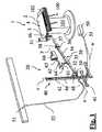
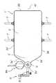
図1〜図6は、患者500の下肢を位置決めするための、本発明の第1の実施形態による位置決め装置20と、位置決め装置20と組み合わされているアダプタ板1とを備えている、手術用位置決めシステムを示している。 1 to 6 show a surgical device comprising a
アダプタ板1は、手術台100に堅固に係止されている。本発明の説明を完全にするために、また、本発明のより良い理解のために、以下において、アダプタ板1および手術台100について概説する。 The
手術台100は、X線不透過性材料(例えば金属材料などの)から成る支持板102を保持している中心柱101を備えている。 The operating table 100 includes a
アダプタ板1は、手術台の支持板102と重なる第1部分2を有している。第1部分2は、実質的に矩形状である。第1部分2の幅は、第1部分2によって部分的に覆われている支持板102の幅と同等である。したがって、第1部分2は、実質的に、支持板102の外周面の延長上にある互いに平行な2つの側面2a、および支持板102の外周面の延長上にない底面2bを有している。 The
アダプタ板1は、さらに、全表面において第1部分2に連続しているが、下方に配置されている支持板102の外周面を越えて延在する第2部分3を有している。したがって、この第2部分3は、アダプタ板1を手術台100に係止したときに、手術台100から横方向にはみ出る。 The
手術台100に固定された、C字状のアームを有するX線撮影装置300(好ましくはフルオロスコープ)が、アダプタ板1の第2部分3を跨ぐように配置されている。 An X-ray imaging apparatus 300 (preferably a fluoroscope) having a C-shaped arm fixed to the operating table 100 is disposed so as to straddle the
アダプタ板1の第2部分3は、実質的に二等辺三角形を形成するように形作られている、すなわち、第1部分2の平行し合う2つの側面2aの、第2部分3側の端から始まって、アダプタ板1の中央長手方向軸m上に位置する端点3bに向かって、互いに収束し合う2つの側面3aを有している。 The
互いに収束し合う2つの側面3aの各々は、中央長手方向軸mに対して、45°〜75°の範囲の角度、例えば60°の角度をなしている。 Each of the two
アダプタ板1は、端点3bに、会陰支持体5を備えている。会陰支持体5は、支持面4から立ち上がり、アダプタ板1のうちの、互いに収束し合う2つの側面3aによって画定される部分より前方(すなわち、突き出た)の位置に配置されている垂直スリーブである。会陰支持体5は、パッド5bによって囲まれている剛性の垂直ピン5aによって構成されていることが好ましい。 The
第2部分3の下面には、会陰支持体5に対向して、会陰支持体5と同軸に円錐状突起8が設けられている。円錐状突起8は、先端部が拡がったシリンダで終端している。このような形状を呈する円錐状突起8により、大腿部持ち上げ装置80(図13および図14に単独で示されている)の結合は可能となっている。大腿部持ち上げ装置80の特性および機能については、後で詳細に説明する。 A
第2部分3の下面には、さらに、中央長手方向軸m上であるが、支持板102の外周面に、より近い位置に、患者500の下肢を位置決めするための位置決め装置20を組み付けるための連結部材6が、下向きに延在している。 On the lower surface of the
この連結部材6は、第2部分3の下面に回転可能に組み付けられている垂直突起6aを有している。この垂直突起6aは、位置決め装置20を取り付けるための部材を組み付けることができる横方向のヒンジ部6bを保持している。 The connecting
上述の第1部分2と第2部分3とは、一様の構造を有しており、どちらも同一のX線透過性材料、特に炭素繊維で作られていることに注意されたい。 It should be noted that the
一様の構造の第1部分2および第2部分3は、互いに重なり合う、機能的に異なる2つの層に分けられる。下層9aは、実際に支持を遂行するための支持構造を呈しており、上層9bは、痛みを緩和するためのクッション構造を呈している。 The
詳細には、下層9aには、第1部分2の、互いに平行な2つの側面2aの各々に沿って、それぞれ1本の側面トラック7aが延在している。それぞれに1本のベルト7を保持するための保持手段を有している2つの摺動可能なスライド7bが、各側面トラック7aに組み付けられている。ベルト7によって、アダプタ板1を、その下方に配置された手術台に迅速に固定することができる。 Specifically, in the
次に、実際の位置決め装置20について説明する。 Next, the
位置決め装置20は、牽引軸xを定める牽引アーム30を備えている。この牽引アーム30の近位端部31は、前述のアダプタ板1のヒンジ部6bにヒンジ結合される。遠位端部32は、後に説明するように、位置決め装置20を支持するための支持枠40にヒンジ結合されている。 The
牽引アーム30は、近位端部31側に、剛体棒から成る近位部分37、遠位端部32側に、遠位部分を有している。 The pulling
遠位部分は、ガイドステム36と、ガイドステム36に平行に隣接して配置されている第1のシリンダアクチュエータ34とで構成されている。ガイドステム36および第1のシリンダアクチュエータ34は、近位部分37の剛体棒と一体化されている近位取り付け具38と、支持枠40にヒンジ結合されている遠位取り付け具39とを連結している。 The distal portion is composed of a
第1のシリンダアクチュエータ34は、ステムレス型、すなわちスラストステムを備えていないピストンを内部に有している空圧複動シリンダである。内部のピストンは、第1のシリンダアクチュエータ34とガイドステム36との両方を囲んでおり、ガイドステム36に沿って、牽引軸xの方向に摺動可能である第1のスライダ35に磁気的に結合されている。したがって、第1のシリンダアクチュエータ34を作動させることによって、牽引アーム30に沿う、第1のスライダ35のストロークを定めることができる。 The
第1のスライダ35は、牽引アーム30に対して直角に上方に延在する剛性ロッド61を保持している。剛性ロッド61の端部には、剛性ロッド61を、支持シャフト63に連結している連結部材62が備えられている。連結部材62の端部には、患者の下肢の遠位端のための結合材60が、一体に組み付けられている。結合材60は、詳細には、公知のタイプの牽引靴の形態で設けられている。連結部材62によって、剛性ロッド61と支持シャフト63との間の角度を変化させることができる。 The
支持シャフト63によって、牽引靴の回転軸yが定められる。連結部材62の内部には、空圧式の回転アクチュエータが存在している。この回転アクチュエータによって、支持シャフト63、および支持シャフト63に組み付けられている牽引靴を、回転軸yのまわりに回転させることができる。空圧システムが機能しなくなったときに(例えば停電のために)、回転操作を可能にするために、緊急用フライホイール64が備えられている。 The
支持枠40は、手術室の床上を移動可能な車輪付き台車41の上に載置されている。 The
この車輪付き台車41は、水平方向に延びるH字状の構造を有している。H字の中心から垂直に延びる直立材42が、延在軸zに沿って立ち上がっている。 The
直立材42に隣接して、第2のシリンダアクチュエータ44が配置されている。この第2のシリンダアクチュエータ44も、ステムレス型の空圧複動シリンダであり、第2のスライダ45に磁気的に結合されている。したがって、第2のスライダ45を、延在軸zに沿って摺動するように制御することができる。 A
第2のスライダ45は、牽引アーム30の遠位取り付け具39にヒンジ結合されている。第2のスライダ45を、第2のシリンダアクチュエータ44による並進移動によって配置された最後の位置に自動的にロックするように構成されている、機械的なロック機構などの、第2のスライダ45のロック手段が設けられていることに留意されたい。このような機械的なロック機構によって、空圧システムが機能停止したとき(例えば停電のとき)にも、第2のスライダ45は、その時点の位置に保持される。 The
同様のロック手段が、第1のスライダ35に対しても設けられており、第2のスライダ45の場合と同様に、停止ブレーキおよび安全ロックとして働くように構成されている。 Similar locking means is also provided for the
このようなロック手段自体は、公知であるから、説明を簡単にするために、これ以上の言及は行わない。 Since such locking means are known per se, no further reference will be made to simplify the description.
さらに、支持枠40の下端には、第2のスライダ45が下端ストローク位置にあるときに、引き出すことができるようになっている1つ以上の支持輪が設けられている。必要に応じて、この支持輪を用いることにより、車輪付き台車41を横方向に移動させることができる。実際、車輪付き台車41に固定されている車輪は、患者の方向に向かうようにロックされており、したがって、車輪付き台車41は、横方向に移動することができないことに注意されたい。支持輪は、引き出されたときに、横方向への移動を可能にするように、車輪付き台車41の車輪に対して直角に取り付けられている。 Further, at the lower end of the
位置決め装置20は、第1のシリンダアクチュエータ34、第2のシリンダアクチュエータ44、および回転アクチュエータに接続されている空圧システムを備えている。この空圧システムを、流入接続部52を介して、圧縮空気分配システムの壁取り付け流出口51に適切に接続することができる。空圧システムは、さらに、可撓接続部53を介して、支持枠40に接続されている制御ユニット50を備えている。制御ユニット50は、手術中に執刀医によって操作されるペダルインターフェースを有する制御ボックスとして構成されている。 The
位置決め装置20は、牽引靴を介して位置決め装置20に繋がれている患者の下肢に、様々な変位を与えることができる。 The
回転アクチュエータの作動によって、回転軸yのまわりの、牽引靴の回転が得られる。それによって、患者の下肢の内旋または外旋がもたらされる。 Actuation of the rotary actuator results in rotation of the traction shoe about the rotation axis y. This results in internal or external rotation of the patient's lower limb.
第1のシリンダアクチュエータ34は、牽引軸xに沿う、牽引靴の並進移動を可能にする。それによって、患者の下肢の牽引や牽引の解除の遂行が可能になる。 The
第2のシリンダアクチュエータ44は、延在軸zに沿う、牽引アーム30の遠位端部32の昇降を可能にする。それによって、患者の下肢の屈伸の遂行が可能になる。 The
最後に、牽引アームの近位端部31が、アダプタ板1の連結部材6にヒンジ結合されているから、上述の支持輪を引き出して、車輪付き台車41を、円弧wに沿って移動させることができる。このような移動によって、患者の下肢の内転/外転運動が遂行される。 Finally, since the
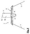
図3に示すように、位置決め装置20の非使用時に、位置決め装置20の収納のために、牽引アーム30を、支持枠40の直立材42に寄せて折り畳むことができることに注意されたい。このような場合には、剛性ロッド61が、牽引アーム30の外側に移動するように、剛性ロッド61は、180°回転させられることに注意されたい。 Note that, as shown in FIG. 3, when the
図7〜図12には、上述の、手術用位置決めシステムの改良された一実施形態が示されている。 FIGS. 7-12 show an improved embodiment of the above-described surgical positioning system.
改良された、この手術用位置決めシステムは、本発明の第2の実施形態による、患者500の下肢の位置決め装置20’ 、および位置決め装置20’に組み合わされているアダプタ板1’を備えている。 This improved surgical positioning system comprises a positioning device 20 'for the lower limb of a
説明を完全にするために、また本発明のより良い理解のために、本発明のこの第2の実施形態におけるアダプタ板1’について、以下に概説する。 For the sake of completeness and for a better understanding of the invention, the adapter plate 1 'in this second embodiment of the invention is outlined below.
第2の実施形態によるアダプタ板1’は、図9〜図12に詳細に示されている。これらの図において、第1の実施形態による前述の要素と同一または同等の要素には、第1の実施形態の場合の符号と同じ符号を付してある。 The
第2の実施形態によるアダプタ板1’は、患者500の下肢を位置決めするための位置決め装置20’に連結されるようになっている連結部材6’の形態が異なるという点を除いて、第1の実施形態におけるアダプタ板1と実質的に同じである。 The
図11および図12に詳細に示されている、この改良された実施形態においては、連結部材6’は、牽引アーム30’の近位部分37’を備えている。逆に、牽引アーム30’の遠位部分である第1のシリンダアクチュエータ34’およびガイドステム36’は、位置決め装置の一部分のままであり、直線ジョイント6c’を介して、連結部材6’に連結されている。 In this improved embodiment, shown in detail in FIGS. 11 and 12, the connecting member 6 'comprises the proximal portion 37' of the traction arm 30 '. Conversely, the first cylinder actuator 34 'and the guide stem 36', which are the distal part of the traction arm 30 ', remain part of the positioning device and are connected to the connecting member 6' via the linear joint 6c '. Has been.
連結部材6’は、詳細には、アダプタ板1’の第2部分3’の下方に延在する垂直突起6a’を有している。垂直突起6a’は、垂直突起6a’を覆っている部分のアダプタ板に、垂直軸のまわりに回転可能に関節接続されている。 Specifically, the connecting
垂直突起6a’の下に、牽引アーム30’の、剛体棒から成る上述の近位部分37’の近位端部31’が、水平軸のまわりに回転可能にヒンジ結合されている。 Under the
剛体棒から成る近位部分37’の遠位端には、近位部分37’と直線ジョイント6c’とを連結しているスペーサ素子6d’が組み合わされている。スペーサ素子6d’は、近位部分37’と直線ジョイント6c’とがなす互いに平行な2つの軸に対して直角方向に延びている。詳細には、スペーサ素子6d’の寸法は、牽引アーム30’が、患者500の下肢に並ぶように、患者500の下肢の下方に直線ジョイント6c’の位置を決めることができるような寸法とされている。 A
スペーサ素子6d’は、施術される患者の下肢に適合しうるように、連結部材6’の配置を調整することができるように、スペーサ素子6d’のロッキングを解除して、スペーサ素子6d’が、近位部分37’の軸のまわりに180°まで回転することができるノブ6e’を備えていることに注意されたい。 The
上述の連結部材6’全体が、X線透過性材料で作られていることが好ましい。 The entire connecting member 6 'is preferably made of an X-ray transparent material.
改良された実施形態における連結部材6’は、前述の第1の実施形態における連結部材6に比して、いくつかの利点を有している。 The connecting member 6 'in the improved embodiment has several advantages over the connecting
第1に、位置決め装置への連結は、直線ジョイントを介して行われ、牽引アームの関節点において行われるのではない。これにより、位置決め装置の連結操作が単純化され、また、潜在的な破断点である連結点に印加される応力は低下する。 First, the connection to the positioning device is made via a linear joint and not at the joint point of the traction arm. This simplifies the coupling operation of the positioning device and reduces the stress applied to the coupling point, which is a potential break point.
さらに、スペーサ素子6d’の存在によって、牽引アームの2つの部分間のずれが容認される。したがって、遠位部分と患者の下肢との完全な位置合わせが可能になり、また位置決め装置によって行われる操作の精度の向上が可能になる。 Furthermore, the presence of the
最後に、スペーサ素子より下の装置を構造的に分割することによって、その装置の、外科的介入中にフルオロスコープの動作域内に位置する全部分を、X線透過性材料で作ることができる。 Finally, by structurally dividing the device below the spacer element, the entire portion of the device that is located within the operating area of the fluoroscope during surgical intervention can be made of a radiolucent material.
次に、第2の実施形態による、実際の位置決め装置20’について説明する。 Next, an actual positioning device 20 'according to the second embodiment will be described.
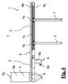
第2の実施形態における位置決め装置20’は、図7および図8に詳細に示されている。これらの図において、第1の実施形態に関して前述した要素と同一または同等の要素には、第1の実施形態の場合の符号と同じ符号を付してある。 The
この場合にも、第1の実施形態の場合と実質的に同じ部品の説明については、前述の説明を参照されたい。以下の説明においては、第2の実施形態に関して、第1の実施形態の場合と異なる態様のみについて述べる。 Also in this case, refer to the above description for the description of substantially the same components as in the first embodiment. In the following description, only aspects different from the case of the first embodiment will be described with respect to the second embodiment.
最初に、この場合には、牽引アーム30’は、その一部において、アダプタ板1’の連結部材6’によって占められており、位置決め装置20’に属するのは、遠位部分(第1のシリンダアクチュエータ34’および互いに平行な2本のガイドステム36’)のみであることに留意されたい。具体的には、近位部分37’に対してずれている、この遠位部分によって、患者500の下肢と平行な牽引軸x’が定められる。 Initially, in this case, the
遠位部分自体は、第1の実施形態の場合と異なる構造を有している。すなわち、遠位部分は、遠位取り付け具39’を近位取り付け具38’に連結している、2本の平行なガイドステム36’を有している。近位取り付け具38’は、上述の直線ジョイント6c’と組み合うように構成されている。 The distal portion itself has a different structure than in the first embodiment. That is, the distal portion has two parallel guide stems 36 'connecting the distal fitting 39' to the proximal fitting 38 '. The proximal fixture 38 'is configured to mate with the linear joint 6c' described above.
第1のシリンダアクチュエータ34’(この場合にも、ステムレス型の空圧複動シリンダで構成されている)は、2本の平行なガイドステム36’の間で、それらのガイドステム36’よりわずかに低くなる位置に配置されている。 The first cylinder actuator 34 '(again comprised of a stemless pneumatic double acting cylinder) is slightly between the two parallel guide stems 36' than the guide stems 36 '. It is arranged at the position where it becomes low.
第1のスライダ35’が、2本のガイドステム36’、およびそれらのガイドステム36’の間に配置されている第1のシリンダアクチュエータ34’を囲んでいる。 A first slider 35 'surrounds two guide stems 36' and a first cylinder actuator 34 'disposed between the guide stems 36'.
第1のスライダ35’は、第1の実施形態の場合のような剛性ロッドを有しておらず、牽引軸x’に沿って位置調整可能なスライド61’を有している。スライド61’上には、第1の実施形態の場合のように、支持シャフト63’および牽引靴である結合材60’を有する、位置調節可能な連結部材62’が設けられている。 The
支持枠40’の構造は、全体的な機械抗力をより大きくするために、直立材42’と第2のシリンダアクチュエータ44’との組み合わせが二重になっているという点を除いて、前述の第1の実施形態の場合の構造と実質的に同じである。 The structure of the support frame 40 'is the same as that described above, except that the combination of the upright material 42' and the second cylinder actuator 44 'is doubled to increase the overall mechanical drag. The structure is substantially the same as that of the first embodiment.
さらに、図7は、支持枠40’が横方向に動くことを可能にする格納式支持輪46’を示してあることに留意されたい。このような素子については、図面の明確化のために、第1の実施形態に関する図面においては省略されている。 In addition, it should be noted that FIG. 7 shows a retractable support wheel 46 'that allows the support frame 40' to move laterally. Such elements are omitted in the drawings relating to the first embodiment for the sake of clarity.
さらに、第2の実施形態における空気圧システムは、第1の実施形態における空気圧システムと実質的に同じである。図面の明確化のために、図7においては、壁取り付け流出口51’および制御ユニット50’の、支持枠40’への接続部は省略されている。 Furthermore, the pneumatic system in the second embodiment is substantially the same as the pneumatic system in the first embodiment. For the sake of clarity of illustration, in FIG. 7, the connection of the wall-mounted outlet 51 'and the control unit 50' to the support frame 40 'is omitted.
最後に、上述の第2の実施形態において、折り畳み位置で、第2のスライダ45’は、上端ストローク位置に位置を定められ、その結果、牽引アーム30’は、支持枠40’の柱に沿うように下向きに折り畳まれることに注意されたい。図8に示されている折り畳みモードにおいて、連結部材62’は、180°回転するようになっていない。 Finally, in the second embodiment described above, in the folded position, the second slider 45 'is positioned at the upper end stroke position so that the traction arm 30' follows the column of the support frame 40 '. Note that it folds downwards. In the folding mode shown in FIG. 8, the connecting member 62 'does not rotate 180 °.
本発明のこの第2の実施形態においても、第1および第2のスライダ35’および45’を、それぞれ第1および第2のシリンダアクチュエータ34’および44’による並進移動によって配置された最後の位置に自動的にロックするように構成された、第1および第2のスライダ35’および45’のロック手段が設けられている。このようなロック手段は、停止ブレーキとしても、空圧システムが機能しなくなったとき(例えば停電のために)の安全ロックとしても働く。 Also in this second embodiment of the present invention, the first and second sliders 35 'and 45' are placed in their final positions by translational movement by the first and second cylinder actuators 34 'and 44', respectively. There is provided locking means for the first and second sliders 35 'and 45', which are configured to automatically lock to each other. Such a locking means serves both as a stop brake and as a safety lock when the pneumatic system fails (eg due to a power failure).
本発明は、さらに、並進可能な第2のスライダ45、45’の並進移動の間、第1のスライダ35、35’のロックを自動的に解除しておくように構成されている、第1のスライダ35、35’に対する解除手段を備えているという新規な特徴を有している。 The present invention is further configured to automatically unlock the
したがって、第2のシリンダアクチュエータ44、44’による、患者の下肢の伸展操作または屈曲操作(下肢の引き下ろし、または持ち上げ)の遂行のたびに、牽引アームの機械的なロックは解除される。すなわち、第1のスライダ35、35’の運動は束縛されなくなり、牽引は自動的に解除される。これによって、患者の下肢の筋肉は、さらなる牽引を受けることがなくなる。したがって、筋障害の発生が避けられ、術後の患者のいかなる痛みも防がれる。 Accordingly, the mechanical lock of the traction arm is released every time the
停電などの緊急時には、この限りでないことは明らかである。実際、そのような緊急時には、外科的介入を完了させるために、全ての動作は、手動でなされる。したがって、まず、手動で機械的なロックを解除し、次いで、屈曲または伸展を行わせることによって、牽引をもたらす必要がある。 Obviously, this is not the case in an emergency such as a power outage. In fact, in such an emergency, all actions are done manually to complete the surgical intervention. Therefore, it is necessary to first bring about traction by manually releasing the mechanical lock and then allowing the flexion or extension to occur.
第1のシリンダアクチュエータ34、34’および第2のシリンダアクチュエータ44、44’、第1のスライダ35、35’および第2のスライダ45、45’のロック手段、第1のスライダ35、35’の解除手段の各々は、制御ユニット50、50’によって制御される。 Locking means for the
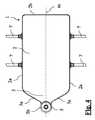
最後に、第1および第2の実施形態において、それぞれアダプタ板1および1’の円錐状突起8および8’に結合可能な大腿部持ち上げ装置80について説明する。 Finally, a
大腿部持ち上げ装置80(図13および図14に単独で示されている)は、円錐状突起8、8’に結合可能なカップ状の結合突起81が突き出ている本体82を有している。患者の下肢のどちら側を手術するのかに応じて、大腿部持ち上げ装置80を、アダプタ板1、1’の端点3b、3b’に対して右方向または左方向に簡単に動かすことができるように、結合突起81は、円錐状突起8、8’に対して回転可能に結合される。 The thigh lifting device 80 (shown alone in FIGS. 13 and 14) has a
本体82は、患者の大腿部を支持するための支持クッション84を、頂部に保持しているラックロッド83を、垂直方向に移動可能に受容している。 The
大腿部持ち上げ装置80は、ラックロッド83と噛み合っており、したがって、各牽引時において、あらかじめ定められた持ち上げ量だけ、支持クッション84を持ち上げる駆動レバー85を備えている。反対方向へのラックロッド83の移動は、解除レバー86の端部に一体化されている適切な突出部によって阻止される。解除レバー86が駆動されると、突出部は、そのロック作用を及ぼさなくなり、支持クッション84は、重力の作用によって下降する。 The
大腿部持ち上げ装置80は、プラスチック材料か、その他の、フルオロスコープの動作を妨害しない任意のX線透過性材料で作られる。 The
当業者であれば、請求項によって定められる本発明の保護範囲から逸脱することなく、特定の条件を付けるように、あるいは特定の要件を満たすように、本発明に種々の変更および変形を加え得ることは明白である。 A person skilled in the art may make various changes and modifications to the present invention so as to give specific conditions or satisfy specific requirements without departing from the scope of protection of the present invention defined by the claims. It is obvious.
1、1’ アダプタ板
2、2’ 第1部分
2a、2a’ 側面
2b、2b’ 底面
3、3’ 第2部分
3a、3a’ 側面
3b、3b’ 端点
4、4’ 支持面
5、5’ 会陰支持体
5a、5a’ 垂直ピン
5b、5b’ パッド
6、6’ 連結部材
6a、6a’ 垂直突起
6b ヒンジ部
6c’ 直線ジョイント
6d’ スペーサ素子
6e’ ノブ
7、7’ ベルト
7a、7a’ 側面トラック
7b、7b’ スライド
8、8’ 円錐状突起
9a、9a’ 下層
9b、9b’ 上層
20、20’ 位置決め装置
30、30’ 牽引アーム
31、31’ 近位端部
32、32’ 遠位端部
34、34’ 第1のシリンダアクチュエータ
35、35’ 第1のスライダ
36、36’ ガイドステム
37、37’ 近位部分
38、38’ 近位取り付け具
39、39’ 遠位取り付け具
40、40’ 支持枠
41、41’ 車輪付き台車
42、42’ 直立材
44、44’ 第2のシリンダアクチュエータ
45、45’ 第2のスライダ
46’ 格納式支持輪
50、50’ 制御ユニット
51、51’ 壁取り付け流出口
52 流入接続部
53 可撓接続部
60、60’ 結合材
61 剛性ロッド
61’ スライド
62、62’ 連結部材
63、63’ 支持シャフト
64 緊急用フライホイール
80 大腿部持ち上げ装置
81 結合突起
82 本体
83 ラックロッド
84 支持クッション
85 駆動レバー
86 解除レバー
100 手術台
101 中心柱
102 支持板
300 X線撮影装置
500 患者
m、m’ 中央長手方向軸
w、w’ 円弧
x、x’ 牽引軸
y、y’ 回転軸
z、z’ 延在軸1, 1 'Adapter plate 2, 2' First part 2a, 2a 'Side surface 2b, 2b' Bottom surface 3, 3 'Second part 3a, 3a' Side surface 3b, 3b 'End point 4, 4' Support surface 5, 5 ' Perineum support 5a, 5a 'Vertical pin 5b, 5b' Pad 6, 6 'Connection member 6a, 6a' Vertical projection 6b Hinge portion 6c 'Linear joint 6d' Spacer element 6e 'Knob 7, 7' Belt 7a, 7a ' Side track 7b, 7b 'Slide 8, 8' Conical projection 9a, 9a 'Lower layer 9b, 9b' Upper layer 20, 20 'Positioning device 30, 30' Pull arm 31, 31 'Proximal end 32, 32' Distal End 34, 34 'first cylinder actuator 35, 35' first slider 36, 36 'guide stem 37, 37' proximal portion 38, 38 'proximal fitting 39, 39' distal fitting 40, 40 'support frame 41, 41' wheeled carriage 42, 42 ' Upright members 44, 44 ′ Second cylinder actuator 45, 45 ′ Second slider 46 ′ Retractable support wheel 50, 50 ′ Control unit 51, 51 ′ Wall-mounted outlet 52 Inlet connection 53 Flexible connection 60, 60 'coupling member 61 rigid rod 61' slide 62, 62 'connecting member 63, 63' support shaft 64 emergency flywheel 80 thigh lifting device 81 coupling projection 82 main body 83 rack rod 84 support cushion 85 drive lever 86 release lever 100 Operating table 101 Central column 102 Support plate 300 X-ray imaging apparatus 500 Patient m, m ′ Central longitudinal axis w, w ′ Arc x, x ′ Traction axis y, y ′ Rotation axis z, z ′ Extension axis
Claims (7)
Translated fromJapaneseApplications Claiming Priority (3)
| Application Number | Priority Date | Filing Date | Title |
|---|---|---|---|
| ITMI2012A001548 | 2012-09-18 | ||
| IT001548AITMI20121548A1 (en) | 2012-09-18 | 2012-09-18 | APPARATUS FOR POSITIONING THE LOWER ARTH OF A PATIENT IN OPERATIVE OFFICE, IN PARTICULAR FOR REPLACEMENT OPERATIONS OF THE ANCHOR WITH A FRONT APPROACH, AND A SURGICAL POSITIONING SYSTEM INCLUDING THE APPLIANCE |
| PCT/IB2013/058616WO2014045199A1 (en) | 2012-09-18 | 2013-09-17 | Apparatus for positioning the lower limb of a patient during operation, in particular for hip replacement operations with anterior approach, and surgical positioning system comprising said apparatus |
Publications (3)
| Publication Number | Publication Date |
|---|---|
| JP2015528367A JP2015528367A (en) | 2015-09-28 |
| JP2015528367A5 JP2015528367A5 (en) | 2016-08-25 |
| JP6163555B2true JP6163555B2 (en) | 2017-07-12 |
Family
ID=47146485
Family Applications (1)
| Application Number | Title | Priority Date | Filing Date |
|---|---|---|---|
| JP2015531679AActiveJP6163555B2 (en) | 2012-09-18 | 2013-09-17 | Device for positioning a patient's lower limb during surgery for hip replacement surgery with an anterior approach, and surgical positioning system comprising this positioning device |
Country Status (8)
| Country | Link |
|---|---|
| US (1) | US10485720B2 (en) |
| EP (1) | EP2897568B1 (en) |
| JP (1) | JP6163555B2 (en) |
| AU (1) | AU2013319888B2 (en) |
| CA (1) | CA2883847C (en) |
| ES (1) | ES2602290T3 (en) |
| IT (1) | ITMI20121548A1 (en) |
| WO (1) | WO2014045199A1 (en) |
Families Citing this family (18)
| Publication number | Priority date | Publication date | Assignee | Title |
|---|---|---|---|---|
| TR201412685A2 (en)* | 2014-10-30 | 2015-02-23 | Osman Nuri Oezyalvac | Surgical table apparatus used in hip fracture surgery. |
| US10751241B2 (en)* | 2014-11-27 | 2020-08-25 | AOD Holdings, LLC | Surgical leg positioner |
| US10485721B2 (en)* | 2014-11-27 | 2019-11-26 | AOD Holdings, LLC | Surgical leg positioner |
| US10335338B2 (en) | 2015-01-02 | 2019-07-02 | Nichols Therapy Systems Llc | Apparatus for applying multi-dimensional traction to the spinal column |
| US11382816B2 (en) | 2015-06-05 | 2022-07-12 | Stryker Corporation | Surgical table and accessories to facilitate hip arthroscopy |
| ITUA20162775A1 (en)* | 2016-04-21 | 2017-10-21 | Medacta Int Sa | ADAPTER FLOOR FOR SURGICAL TABLE AND SURGICAL TABLE |
| CA3052793A1 (en) | 2017-02-06 | 2018-08-09 | Stryker Corp. | Distraction frame for effecting hip distraction |
| US11510805B2 (en) | 2017-02-06 | 2022-11-29 | Stryker Corp. | Anatomical gripping system for gripping the leg and foot of a patient when effecting hip distraction and/or when effecting leg positioning |
| EP3576687B1 (en) | 2017-02-06 | 2025-07-02 | Stryker Corporation | Method and apparatus for supporting and stabilizing a patient during hip distraction |
| CN106726311B (en)* | 2017-02-17 | 2018-10-26 | 广州中医药大学第一附属医院 | An angle-adjustable hip herringbone plaster orthopedic bed |
| USD878836S1 (en) | 2017-08-17 | 2020-03-24 | Stryker Corp. | Table extender |
| IT201800005431A1 (en)* | 2018-05-16 | 2019-11-16 | POSITIONING APPARATUS OF A LIMB OF A PATIENT | |
| CN108836502A (en)* | 2018-05-28 | 2018-11-20 | 西南医科大学附属中医医院 | A kind of ankle arthroscopy operation auxiliary hitch |
| IT202000008854A1 (en)* | 2020-04-24 | 2021-10-24 | Medacta Int Sa | POSITIONING APPARATUS OF A LOWER LIMB OF A PATIENT IN THE OPERATING SITE AND SURGICAL POSITIONING SYSTEM INCLUDING SAID APPARATUS |
| US11564855B2 (en) | 2020-09-28 | 2023-01-31 | Stryker Corporation | Systems and methods for supporting and stabilizing a patient during hip distraction |
| US11918475B2 (en) | 2021-03-31 | 2024-03-05 | DePuy Synthes Products, Inc. | Modular acetabular surgical implant assembly |
| JP7589899B2 (en)* | 2022-10-13 | 2024-11-26 | 国立大学法人千葉大学 | Surgery support table and traction operating table for lower limb joint surgery |
| CN116849975B (en)* | 2023-08-15 | 2024-01-26 | 苏州市立医院 | Orthopedic operation limb auxiliary fixing device and method thereof |
Family Cites Families (48)
| Publication number | Priority date | Publication date | Assignee | Title |
|---|---|---|---|---|
| US1188711A (en)* | 1916-02-01 | 1916-06-27 | John H Wilting | Fracture-setting apparatus. |
| US3745996A (en)* | 1971-02-19 | 1973-07-17 | Berivon Co | Apparatus for the reduction of bone fractures |
| US3766384A (en) | 1971-04-28 | 1973-10-16 | Tower Co Inc | Surgical table |
| US4527555A (en)* | 1981-05-18 | 1985-07-09 | Hermann Ruf | Auxiliary table for extension and repositioning in medical operations |
| US4872656A (en)* | 1981-12-21 | 1989-10-10 | American Sterilizer Company | Orthopedic table with movable upper body and sacrum supports |
| GB8315121D0 (en)* | 1983-06-02 | 1983-07-06 | James Ind Ltd | Invalid hoist |
| FR2632184A1 (en)* | 1988-06-06 | 1989-12-08 | Massaad Raymond | Traction device for an operating table adapted to orthopaedic surgery of the upper limb |
| US5056635A (en) | 1989-04-10 | 1991-10-15 | Grimsley John W | Reversible free wheeling mechanical drive mechanism |
| US5176707A (en)* | 1991-11-04 | 1993-01-05 | Phillips Edward A | Spinal adjustment device |
| US5349956A (en) | 1991-12-04 | 1994-09-27 | Apogee Medical Products, Inc. | Apparatus and method for use in medical imaging |
| US5239716A (en) | 1992-04-03 | 1993-08-31 | Fisk Albert W | Surgical spinal positioning frame |
| US5372147A (en) | 1992-06-16 | 1994-12-13 | Origin Medsystems, Inc. | Peritoneal distension robotic arm |
| FR2708195A1 (en)* | 1993-07-26 | 1995-02-03 | Caffiniere De Jean Yves | Removable traction device independent of the operating table for per-operatory reduction of fractures of the lower limb |
| US5658315A (en)* | 1994-02-23 | 1997-08-19 | Orthopedic Systems, Inc. | Apparatus and method for lower limb traction |
| US5645079A (en)* | 1994-12-02 | 1997-07-08 | Zahiri; Hormoz | Apparatus for mechanically holding, maneuvering and maintaining a body part of a patient during orthopedic surgery |
| US5613255A (en) | 1994-12-27 | 1997-03-25 | Hill-Rom, Inc. | Hospital bed having scissors lifting apparatus |
| WO1997030653A1 (en) | 1996-02-26 | 1997-08-28 | Biopsys Medical, Inc. | Articulating guide arm for medical applications |
| IL117345A0 (en) | 1996-03-04 | 1996-07-23 | Gotfried Yechiel | Height-adjustable support for lower-limb operations |
| US6260220B1 (en) | 1997-02-13 | 2001-07-17 | Orthopedic Systems, Inc. | Surgical table for lateral procedures |
| US6070281A (en) | 1997-04-18 | 2000-06-06 | Siemens Aktiengesellschaft | Patient orientation table |
| US6286164B1 (en)* | 1998-03-19 | 2001-09-11 | Orthopedic Systems, Inc. | Medical table having controlled movement and method of use |
| US6375355B1 (en) | 1999-03-10 | 2002-04-23 | Joseph Fortin | Moveable table |
| JP4273476B2 (en)* | 2000-02-18 | 2009-06-03 | Smc株式会社 | Linear actuator |
| US6643873B2 (en) | 2001-04-27 | 2003-11-11 | Hill-Rom Services, Inc. | Patient support apparatus having auto contour |
| US6862762B1 (en) | 2002-01-11 | 2005-03-08 | Wlf, L.L.C. | Patient support apparatus |
| JP4527929B2 (en)* | 2002-05-08 | 2010-08-18 | 衛 光石 | Reduction device |
| US20040133983A1 (en) | 2003-01-13 | 2004-07-15 | Newkirk David C. | Surgical table |
| ATE495706T1 (en) | 2003-11-14 | 2011-02-15 | Smith & Nephew Inc | ADJUSTABLE SURGICAL CUTTING SYSTEMS |
| JP2005168881A (en) | 2003-12-12 | 2005-06-30 | Mizuho Co Ltd | Subject supporting device |
| WO2005087116A2 (en)* | 2004-03-11 | 2005-09-22 | Branch Thomas P | Method and apparatus for aligning a knee for surgery or the like |
| FR2871050B1 (en)* | 2004-06-08 | 2006-08-11 | Medacta Int Sa | COUPLING SYSTEM AND CONTROL OF A PATIENT ELONGATION MEANS TO OPERATE |
| US7458119B2 (en) | 2004-07-30 | 2008-12-02 | Hill-Rom Services, Inc. | Bed having a chair egress position |
| US20130133137A1 (en) | 2011-11-28 | 2013-05-30 | Roger P. Jackson | Patient positioning support structure with coordinated continuous nonsegmented articulation, rotation and lift, and locking fail-safe device |
| US7565708B2 (en) | 2005-02-22 | 2009-07-28 | Jackson Roger P | Patient positioning support structure |
| US9301897B2 (en) | 2005-02-22 | 2016-04-05 | Roger P. Jackson | Patient positioning support structure |
| US7739762B2 (en) | 2007-10-22 | 2010-06-22 | Mizuho Orthopedic Systems, Inc. | Surgery table apparatus |
| US9186291B2 (en) | 2005-02-22 | 2015-11-17 | Roger P. Jackson | Patient positioning support structure with trunk translator |
| US8707484B2 (en) | 2005-02-22 | 2014-04-29 | Roger P. Jackson | Patient positioning support structure |
| JP5186369B2 (en) | 2005-08-10 | 2013-04-17 | ミズホ・オーソペディック・システムズ・インク | Treatment table with controlled operation and method of using the same |
| US20080203249A1 (en)* | 2007-02-26 | 2008-08-28 | Priest David H | Arm support device |
| US8635725B2 (en) | 2008-10-28 | 2014-01-28 | Tony Y. Tannoury | Prone and laterally angled surgical device and method |
| US8707476B2 (en) | 2009-04-01 | 2014-04-29 | Operating Room Safety Enterprises, LLC | Apparatuses for posterior surgery |
| US8584281B2 (en) | 2011-04-07 | 2013-11-19 | Mizuho Orthopedic Systems, Inc | Surgery table having coordinated motion |
| KR101350716B1 (en) | 2011-11-29 | 2014-01-14 | 주식회사 성우하이텍 | Roll forming method and formed beam produced by using the same |
| DE202012101347U1 (en)* | 2012-04-13 | 2012-06-27 | Condor Gmbh Medicaltechnik | positioning |
| CA2796278C (en) | 2012-11-15 | 2019-04-30 | Kapsch Trafficcom Ag | Methods for prolonging battery life in toll transponders |
| US9961224B2 (en) | 2015-02-16 | 2018-05-01 | Ricoh Company, Ltd. | Information processing apparatus, control method, and recording medium |
| TWI538958B (en) | 2015-05-18 | 2016-06-21 | Nanya Plastics Corp | A preparation method of polyphenylene ether microspore dispersions |
- 2012
- 2012-09-18ITIT001548Apatent/ITMI20121548A1/enunknown
- 2013
- 2013-09-17CACA2883847Apatent/CA2883847C/enactiveActive
- 2013-09-17ESES13801743.9Tpatent/ES2602290T3/enactiveActive
- 2013-09-17USUS14/428,682patent/US10485720B2/ennot_activeExpired - Fee Related
- 2013-09-17AUAU2013319888Apatent/AU2013319888B2/enactiveActive
- 2013-09-17WOPCT/IB2013/058616patent/WO2014045199A1/enactiveApplication Filing
- 2013-09-17EPEP13801743.9Apatent/EP2897568B1/enactiveActive
- 2013-09-17JPJP2015531679Apatent/JP6163555B2/enactiveActive
Also Published As
| Publication number | Publication date |
|---|---|
| CA2883847C (en) | 2016-10-25 |
| AU2013319888A1 (en) | 2015-04-09 |
| WO2014045199A1 (en) | 2014-03-27 |
| ES2602290T3 (en) | 2017-02-20 |
| ITMI20121548A1 (en) | 2014-03-19 |
| US10485720B2 (en) | 2019-11-26 |
| AU2013319888B2 (en) | 2017-01-12 |
| EP2897568A1 (en) | 2015-07-29 |
| CA2883847A1 (en) | 2014-03-27 |
| US20150231013A1 (en) | 2015-08-20 |
| EP2897568B1 (en) | 2016-08-17 |
| JP2015528367A (en) | 2015-09-28 |
Similar Documents
| Publication | Publication Date | Title |
|---|---|---|
| JP6163555B2 (en) | Device for positioning a patient's lower limb during surgery for hip replacement surgery with an anterior approach, and surgical positioning system comprising this positioning device | |
| JP6185997B2 (en) | Adapter plate for operating table especially used for hip replacement surgery with anterior approach | |
| US20220362083A1 (en) | Linkage mechanisms for mounting robotic arms to a surgical table | |
| KR101336214B1 (en) | Medical table having controlled movement and method of use | |
| AU2013217089B2 (en) | Surgical table with moveable perineal post | |
| US20100263129A1 (en) | Lower Extremity Surgical Positioning Device | |
| KR20190043543A (en) | Table adapter for mounting robot arm to surgical table | |
| JP2017121491A (en) | Patient positioning support structure | |
| WO2018145108A1 (en) | Distraction frame for effecting hip distraction | |
| US10799412B1 (en) | Surgical table for direct anterior surgical approach of the hip | |
| US10912698B1 (en) | Table attachment for direct anterior surgical approach of the hip | |
| WO2019204000A1 (en) | Surgical robotic systems | |
| JP7680959B2 (en) | SYSTEM AND APPARATUS FOR PROVIDING LIFT ASSISTANCE FOR SURGICAL PROCEDURES - Patent application | |
| CN110787019A (en) | Traction device and traction bed using the same | |
| CN107485532A (en) | A kind of new abortion's bed |
Legal Events
| Date | Code | Title | Description |
|---|---|---|---|
| A521 | Request for written amendment filed | Free format text:JAPANESE INTERMEDIATE CODE: A523 Effective date:20160707 | |
| A621 | Written request for application examination | Free format text:JAPANESE INTERMEDIATE CODE: A621 Effective date:20160707 | |
| A977 | Report on retrieval | Free format text:JAPANESE INTERMEDIATE CODE: A971007 Effective date:20170529 | |
| TRDD | Decision of grant or rejection written | ||
| A01 | Written decision to grant a patent or to grant a registration (utility model) | Free format text:JAPANESE INTERMEDIATE CODE: A01 Effective date:20170606 | |
| A61 | First payment of annual fees (during grant procedure) | Free format text:JAPANESE INTERMEDIATE CODE: A61 Effective date:20170619 | |
| R150 | Certificate of patent or registration of utility model | Ref document number:6163555 Country of ref document:JP Free format text:JAPANESE INTERMEDIATE CODE: R150 | |
| R250 | Receipt of annual fees | Free format text:JAPANESE INTERMEDIATE CODE: R250 | |
| R250 | Receipt of annual fees | Free format text:JAPANESE INTERMEDIATE CODE: R250 | |
| R250 | Receipt of annual fees | Free format text:JAPANESE INTERMEDIATE CODE: R250 | |
| R250 | Receipt of annual fees | Free format text:JAPANESE INTERMEDIATE CODE: R250 | |
| R250 | Receipt of annual fees | Free format text:JAPANESE INTERMEDIATE CODE: R250 | |
| R250 | Receipt of annual fees | Free format text:JAPANESE INTERMEDIATE CODE: R250 |