JP6163478B2 - Stent delivery system - Google Patents
Stent delivery systemDownload PDFInfo
- Publication number
- JP6163478B2 JP6163478B2JP2014500121AJP2014500121AJP6163478B2JP 6163478 B2JP6163478 B2JP 6163478B2JP 2014500121 AJP2014500121 AJP 2014500121AJP 2014500121 AJP2014500121 AJP 2014500121AJP 6163478 B2JP6163478 B2JP 6163478B2
- Authority
- JP
- Japan
- Prior art keywords
- delivery system
- stent delivery
- inner tube
- stent
- tube body
- Prior art date
- Legal status (The legal status is an assumption and is not a legal conclusion. Google has not performed a legal analysis and makes no representation as to the accuracy of the status listed.)
- Active
Links
Images


Classifications
- A—HUMAN NECESSITIES
- A61—MEDICAL OR VETERINARY SCIENCE; HYGIENE
- A61F—FILTERS IMPLANTABLE INTO BLOOD VESSELS; PROSTHESES; DEVICES PROVIDING PATENCY TO, OR PREVENTING COLLAPSING OF, TUBULAR STRUCTURES OF THE BODY, e.g. STENTS; ORTHOPAEDIC, NURSING OR CONTRACEPTIVE DEVICES; FOMENTATION; TREATMENT OR PROTECTION OF EYES OR EARS; BANDAGES, DRESSINGS OR ABSORBENT PADS; FIRST-AID KITS
- A61F2/00—Filters implantable into blood vessels; Prostheses, i.e. artificial substitutes or replacements for parts of the body; Appliances for connecting them with the body; Devices providing patency to, or preventing collapsing of, tubular structures of the body, e.g. stents
- A61F2/95—Instruments specially adapted for placement or removal of stents or stent-grafts
- A61F2/962—Instruments specially adapted for placement or removal of stents or stent-grafts having an outer sleeve
- A61F2/966—Instruments specially adapted for placement or removal of stents or stent-grafts having an outer sleeve with relative longitudinal movement between outer sleeve and prosthesis, e.g. using a push rod
- A—HUMAN NECESSITIES
- A61—MEDICAL OR VETERINARY SCIENCE; HYGIENE
- A61B—DIAGNOSIS; SURGERY; IDENTIFICATION
- A61B17/00—Surgical instruments, devices or methods
- A—HUMAN NECESSITIES
- A61—MEDICAL OR VETERINARY SCIENCE; HYGIENE
- A61F—FILTERS IMPLANTABLE INTO BLOOD VESSELS; PROSTHESES; DEVICES PROVIDING PATENCY TO, OR PREVENTING COLLAPSING OF, TUBULAR STRUCTURES OF THE BODY, e.g. STENTS; ORTHOPAEDIC, NURSING OR CONTRACEPTIVE DEVICES; FOMENTATION; TREATMENT OR PROTECTION OF EYES OR EARS; BANDAGES, DRESSINGS OR ABSORBENT PADS; FIRST-AID KITS
- A61F2/00—Filters implantable into blood vessels; Prostheses, i.e. artificial substitutes or replacements for parts of the body; Appliances for connecting them with the body; Devices providing patency to, or preventing collapsing of, tubular structures of the body, e.g. stents
- A61F2/02—Prostheses implantable into the body
- A61F2/04—Hollow or tubular parts of organs, e.g. bladders, tracheae, bronchi or bile ducts
- A61F2/06—Blood vessels
- A—HUMAN NECESSITIES
- A61—MEDICAL OR VETERINARY SCIENCE; HYGIENE
- A61F—FILTERS IMPLANTABLE INTO BLOOD VESSELS; PROSTHESES; DEVICES PROVIDING PATENCY TO, OR PREVENTING COLLAPSING OF, TUBULAR STRUCTURES OF THE BODY, e.g. STENTS; ORTHOPAEDIC, NURSING OR CONTRACEPTIVE DEVICES; FOMENTATION; TREATMENT OR PROTECTION OF EYES OR EARS; BANDAGES, DRESSINGS OR ABSORBENT PADS; FIRST-AID KITS
- A61F2/00—Filters implantable into blood vessels; Prostheses, i.e. artificial substitutes or replacements for parts of the body; Appliances for connecting them with the body; Devices providing patency to, or preventing collapsing of, tubular structures of the body, e.g. stents
- A61F2/95—Instruments specially adapted for placement or removal of stents or stent-grafts
- A61F2/9517—Instruments specially adapted for placement or removal of stents or stent-grafts handle assemblies therefor
Landscapes
- Health & Medical Sciences (AREA)
- Engineering & Computer Science (AREA)
- Biomedical Technology (AREA)
- Life Sciences & Earth Sciences (AREA)
- General Health & Medical Sciences (AREA)
- Animal Behavior & Ethology (AREA)
- Heart & Thoracic Surgery (AREA)
- Veterinary Medicine (AREA)
- Public Health (AREA)
- Oral & Maxillofacial Surgery (AREA)
- Cardiology (AREA)
- Transplantation (AREA)
- Vascular Medicine (AREA)
- Surgery (AREA)
- Nuclear Medicine, Radiotherapy & Molecular Imaging (AREA)
- Molecular Biology (AREA)
- Medical Informatics (AREA)
- Gastroenterology & Hepatology (AREA)
- Pulmonology (AREA)
- Media Introduction/Drainage Providing Device (AREA)
Description
Translated fromJapanese本発明は、血管等の生体管腔内にステントを送達、留置するためのステントデリバリーシステムに関する。 The present invention relates to a stent delivery system for delivering and placing a stent in a biological lumen such as a blood vessel.
従来から、血管、胆管、気管、食道、尿道等の生体管腔内に生じた狭窄部や閉塞部の改善のため、金属線材等によって多数の側壁開口を有する円筒形状に形成され、生体管腔内で拡張可能なステントが用いられることがある。 Conventionally, in order to improve stenosis and obstruction occurring in living body lumens such as blood vessels, bile ducts, trachea, esophagus, urethra, etc., it has been formed into a cylindrical shape having a large number of side wall openings by metal wire etc. An expandable stent may be used.
例えば、ステント自体が自己拡張機能を備えた自己拡張型ステントである場合、このステントを内管と外管の間の間隙に圧縮・収納した状態で生体内へと送達し、外管を基端側に後退させることで放出して所望の管腔内に留置するためのステントデリバリーシステムが知られている。 For example, when the stent itself is a self-expanding stent having a self-expanding function, the stent is delivered to the living body in a state of being compressed and stored in a gap between the inner tube and the outer tube, and the outer tube is moved to the proximal end. Stent delivery systems are known for release by retracting to the side for placement within a desired lumen.
本出願人は、国際公開第2011/122444号パンフレットにおいて、この種のステントを備えたステントデリバリーシステムを提案しており、該ステントデリバリーシステムは、外管を内管に対して進退動作させる操作部を備え、前記操作部のローラを術者が回転させることでローラの歯車に噛合されたラック部材を介して外管を移動させステントの放出を行う。 In the international publication 2011/122444 pamphlet, the present applicant has proposed a stent delivery system provided with this type of stent, and the stent delivery system has an operation unit for moving the outer tube forward and backward with respect to the inner tube. When the operator rotates the roller of the operation section, the outer tube is moved through the rack member meshed with the gear of the roller to release the stent.
本発明の一般的な目的は、外管が移動した際における内管の変形を防止し、ステントを生体管腔内の所望部位に確実に留置可能なステントデリバリーシステムを提供することにある。 A general object of the present invention is to provide a stent delivery system capable of preventing a deformation of an inner tube when an outer tube is moved and reliably placing a stent at a desired site in a living body lumen.
本発明は、内管と、生体管腔内挿入時に中心軸方向に圧縮されて前記内管の先端側に配置され、生体管腔内留置時には外方に拡張して圧縮前の形状に復元可能なステントと、前記内管の外面側に配置されることで前記ステントを内腔に収納可能であると共に、前記内管に対して基端方向に移動することにより、前記ステントを外部に放出可能な外管と、前記内管に対して前記外管を軸方向に移動させるための操作部とを備えるステントデリバリーシステムであって、 The present invention is an inner tube and is compressed in the direction of the central axis when inserted into a living body lumen and disposed on the distal end side of the inner tube, and can be expanded outwardly when being placed in the living body lumen to be restored to its original shape before compression. The stent can be accommodated in the lumen by being placed on the outer surface side of the inner tube and the inner tube, and the stent can be released to the outside by moving in the proximal direction with respect to the inner tube A stent delivery system comprising: an outer tube; and an operation unit for moving the outer tube in an axial direction relative to the inner tube,
前記操作部は、ハウジングと、該ハウジングの内部に収納された前記外管に接続される連結体と、を備え、前記ハウジングの内部には、前記連結体が軸方向に移動可能に保持される収納溝が設けられ、前記連結体の基端と前記収納溝の基端との間に、該内管の外周側を保護する保護体が設けられることを特徴とする。
The operation unit includes a housingand a coupling body connected to the outer tube housed in the housing, and the coupling body is held in the housing so as to be movable in the axial direction. A storage groove is provided, and a protective body for protecting the outer peripheral side of the inner tube is provided betweenthe base end of thecoupling body and the base end of the storage groove .
従来から、例えば、ステントを放出させるために操作部を操作して外管を内管に対して基端側へと移動させた際、前記外管から前記内管に応力が付与されることがあるが、本発明によれば、ステントデリバリーシステムにおいて、操作部のハウジングに連結された内管の基端と外管の基端との間に、該内管の外周側を保護するように保護体を設けることにより、前記外管から前記内管に応力が付与された場合でも、前記内管の外周側に設けられた保護体に該内管が接触することで、前記内管の変形が防止される。 Conventionally, for example, when the outer tube is moved to the proximal side with respect to the inner tube by operating the operation unit to release the stent, stress is applied from the outer tube to the inner tube. However, according to the present invention, in the stent delivery system, protection is provided so as to protect the outer peripheral side of the inner tube between the proximal end of the inner tube and the proximal end of the outer tube connected to the housing of the operation unit. Even if stress is applied to the inner tube from the outer tube by providing the body, the inner tube is brought into contact with a protective body provided on the outer peripheral side of the inner tube, so that the inner tube is deformed. Is prevented.
従って、例えば、内管の変形に起因した外管の動作不良が確実に防止され、ステントを生体管腔内の所望部位に確実に留置することが可能となる。 Therefore, for example, the malfunction of the outer tube due to the deformation of the inner tube is reliably prevented, and the stent can be reliably placed at a desired site in the living body lumen.
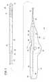
このステントデリバリーシステム10は、図1に示されるように、管状に形成された内側チューブ体(内管)12と、該内側チューブ体12の外周側に設けられる外側チューブ体(外管)14と、前記内側チューブ体12と外側チューブ体14との間に収納された拡張可能なステント16と、前記外側チューブ体14を前記内側チューブ体12に対して移動させるための操作部18とを含む。 As shown in FIG. 1, the
なお、図1において、内側チューブ体12及び外側チューブ体14の左側を「基端(後端)」側(矢印A方向)、前記内側チューブ体12及び外側チューブ体14の右側を「先端」側(矢印B方向)と呼び、他の各図についても同様とする。 In FIG. 1, the left side of the
内側チューブ体12は、図1に示されるように、ガイドワイヤを挿通するためのガイドワイヤルーメンが形成された第1先端チューブ20と、前記第1先端チューブ20の基端側(矢印A方向)に連結部材26を介して連結された第1基端チューブ22と、前記第1基端チューブ22の基端に接続されたコネクタ24とを有する。 As shown in FIG. 1, the
この内側チューブ体12は、管状体からなり、第1先端チューブ20及び第1基端チューブ22の先端及び基端がそれぞれ開口すると共に、前記第1先端チューブ20の先端が、外側チューブ体14の先端から突出するように配置される。なお、上述したガイドワイヤは、例えば、ステントデリバリーシステム10を生体管腔内の病変部に導くために用いられる。 The
そして、内側チューブ体12は、外側チューブ体14の内部において第1先端チューブ20の基端と第1基端チューブ22の先端とが連結部材26を介して連結されると共に、前記第1基端チューブ22は、その先端から基端まで貫通するルーメンを有し、該ルーメンにはコネクタ24を通じて生理食塩水等の液体が注入される。 The
外側チューブ体14は、管状体からなり、内部に内側チューブ体12の第1先端チューブ20が配置される第2先端チューブ28と、該第2先端チューブ28の基端側(矢印A方向)に連結され内部に第1基端チューブ22が配置される第2基端チューブ30とを有する。なお、第2先端チューブ28の先端は、生体管腔内の病変部にステント16を留置する際の放出口として機能すると共に、途中まで放出された前記ステント16を回収する際の収納口としても機能する。 The
また、第2先端チューブ28の基端には、該第2先端チューブ28の内腔と外部とを連通する開口したガイドワイヤ導出孔32が形成され、内部に設けられた第1先端チューブ20のガイドワイヤルーメンの開口と連通可能に設けられる。このガイドワイヤ導出孔32を通じて内側チューブ体12のガイドワイヤルーメンにガイドワイヤを挿通させる。 An open guide wire lead-out
ステント16は、多数の開口を有したメッシュ状で略円筒形状に形成される。このステント16は、生体管腔内への挿入時には外側チューブ体14の第2先端チューブ28と内側チューブ体12の第1先端チューブ20との間において中心軸方向となる半径内方向に圧縮されて配置され、前記外側チューブ体14の先端から前記生体管腔内の病変部に放出されることにより、半径外方向に拡張して圧縮前の形状へと復元可能な自己拡張型ステントである。 The
操作部18は、図1及び図2に示されるように、ハウジング34と、該ハウジング34の内部に収納され外側チューブ体14に接続されるラック部材(連結体)36と、前記ラック部材36に噛合される歯車38を有し該ラック部材36を直線移動させる回転ローラ40とを含む。 As shown in FIGS. 1 and 2, the
ハウジング34は、その中央部が丸みを帯びた形状で形成され、その略中央部には回転ローラ40を収納可能なローラ収納部42が形成され、該回転ローラ40の一部が前記ローラ収納部42に形成されたローラ孔44を介して外部に露呈する。なお、回転ローラ40は、ハウジング34の内壁面に形成された一対の軸受(図示せず)によって回転自在に支持される。 The
また、ハウジング34の内部には、ラック部材36が軸方向(矢印A、B方向)に移動可能に収納され保持される一組の収納溝46a、46bがそれぞれ形成され、前記収納溝46bの基端側(矢印A方向)には、コネクタ24が収納されるコネクタ収納部48が形成され、前記コネクタ24が前記コネクタ収納部48に収納されることによってハウジング34に対して固定される。これにより、内側チューブ体12を構成する第1基端チューブ22の基端がコネクタ24を介して操作部18に固定される。 A pair of
一方、ハウジング34の先端には、外側チューブ体14の第2基端チューブ30を摺動可能に保持する先端ノズル50が装着され、該先端ノズル50の内部には、前記第2基端チューブ30が挿通される貫通孔(図示せず)が形成される。 On the other hand, a
ラック部材36は、直線状に形成され、且つ、略対称形状に形成された一組の第1及び第2ブロック体52、54からなり、外側チューブ体14における第2基端チューブ30の基端が、前記第1ブロック体52と前記第2ブロック体54との間に挟持されることによって固定される。この場合、内側チューブ体12は、外側チューブ体14の内部を自在に移動することが可能である。 The
そして、第1及び第2ブロック体52、54からなるラック部材36が、ハウジング34の内部において収納溝46a、46bに挿入されることによって該ハウジング34の先端及び基端側(矢印A、B方向)に向かって直線的に移動可能な状態で保持されることとなる。 The
また、第2ブロック体54は、ハウジング34の内部において回転ローラ40に臨むように設けられ、該回転ローラ40に臨む側面には軸方向(矢印A、B方向)に沿って凹凸状に形成された複数の歯部56が設けられる。 The
さらに、図1〜図3Bに示されるように、内側チューブ体12の基端と外側チューブ体14の基端との間、より具体的には、ラック部材36の基端と収納溝46bの基端との間には、例えば、樹脂製材料から蛇腹状の筒体で形成された保護体58が設けられ、該保護体58は軸方向(矢印A、B方向)に伸縮自在に形成されると共に、その先端が第1及び第2ブロック体52、54の基端に当接し、基端が収納溝46bの基端となる壁面に当接している(図3A及び図3B参照)。すなわち、保護体58は、ラック部材36と収納溝46bとを接続するように介装されている。また、保護体58の内部には、その略中央部軸方向に沿って内側チューブ体12を構成する第1基端チューブ22が挿通されている。 Furthermore, as shown in FIGS. 1 to 3B, between the base end of the
なお、保護体58の材質及び形状は、ラック部材36が基端側(矢印A方向)へと移動する際の推力に対して前記保護体58の弾性力が小さくなるものが選択される。 The material and the shape of the
回転ローラ40は、例えば、ホイール状に形成され、その中心部に設けられた一対の回転軸がハウジング34の軸受(図示せず)にそれぞれ挿入される。また、回転ローラ40の側面には、回転軸を中心とした歯車38が設けられ、ラック部材36の歯部56に噛合される。そして、回転ローラ40が回転することによってラック部材36が収納溝46a、46bに沿って直線的に移動することとなる。また、回転ローラ40の外周部位は、その一部がハウジング34のローラ孔44を介して外部に露呈し、この露呈した部位を介して術者が前記回転ローラ40を回転させる。 The rotating
上述した操作部18では、例えば、術者が回転ローラ40をハウジング34に対して所定方向(図1及び図2中、矢印C方向)に回転させることにより、前記ハウジング34の内部においてラック部材36が収納溝46a、46bに沿ってコネクタ24側(矢印A方向)へと移動し、それに伴って、外側チューブ体14がハウジング34の基端側(矢印A方向)へと移動(後進)する。これにより、ステント16が、外側チューブ体14の先端から放出される。 In the
一方、ステント16を途中まで放出した後、回転ローラ40を前記とは反対方向(図1及び図2中、矢印D方向)に回転させることにより、前記ラック部材36が収納溝46a、46bに沿ってコネクタ24から離間する方向(矢印B方向)へと移動し、それに伴って、前記外側チューブ体14が内側チューブ体12に対して先端側(矢印B方向)に移動(前進)してステント16が前記外側チューブ体14の内部に再収納される。 On the other hand, after releasing the
本発明の実施の形態に係るステントデリバリーシステム10は、基本的には以上のように構成されるものであり、次にその動作並びに作用効果について説明する。 The
先ず、生体管腔内(例えば、血管内)にガイドワイヤを挿入し、その先端が前記生体管腔内の病変部に予め留置した状態とする。そして、術者が操作部18の基端に設けられたコネクタ24に対して液体注入具(図示せず)を接続し、前記液体注入具からコネクタ24へと生理食塩水等の液体を注入する。これにより、この液体が内側チューブ体12及び外側チューブ体14の先端側(矢印B方向)へと流通する。そして、先端まで到達した液体が内側チューブ体12及び外側チューブ体14の先端から吐出することにより、生体外において前記内側チューブ体12及び外側チューブ体14の内部のエア抜き(ブライミング)が完了する。 First, a guide wire is inserted into a living body lumen (for example, inside a blood vessel), and the distal end of the guide wire is placed in advance in a lesioned part in the living body lumen. Then, the operator connects a liquid injection tool (not shown) to the
次に、生体外に露呈しているガイドワイヤの基端を、内側チューブ体12の先端からガイドワイヤルーメンへと挿通させ、前記ガイドワイヤに沿って前記内側チューブ体12及び外側チューブ体14を生体管腔内へと進行させていく。 Next, the proximal end of the guide wire exposed to the outside of the living body is inserted from the distal end of the
そして、外側チューブ体14の先端が病変部に到達したことを図示しない造影マーカーによって確認した後、回転ローラ40を所定方向(矢印C方向)へと回転させる。これにより、歯車38の回転に伴ってラック部材36がハウジング34内で基端側(矢印A方向)へと移動し、それに伴って、外側チューブ体14が前記操作部18の基端側へと徐々に移動する。また、同時に、保護体58は、その内部に内側チューブ体12の第1基端チューブ22が挿通された状態で、徐々に軸方向(矢印A方向)に押し潰されるように圧縮されていく。 Then, after confirming that the distal end of the
その結果、外側チューブ体14内に収容されたステント16が、先端部側から徐々に露出し始めるのと同時に半径外方向に拡張し始め、ステント16が、外側チューブ体14に対して完全に露出した状態となることで、円筒状に拡張した状態で病変部に留置される。 As a result, the
また、上述したようなステント16の放出を行う際に、回転ローラ40の回転作用下にラック部材36を基端側(矢印A方向)へと移動させるが、例えば、内側チューブ体12の歪みや曲がり、あるいはラック部材36の移動時における収納溝46b内でのふらつき等を原因として、前記ラック部材36あるいは外側チューブ体14から内側チューブ体12に対して応力が付与されることがある。 Further, when releasing the
このような場合でも、内側チューブ体12の第1基端チューブ22は、その外周側を覆う(保護する)保護体58の内周面によって前記応力による径方向への変形が規制されているため、前記内側チューブ体12の座屈が確実に防止される。その結果、ステント16を生体管腔内の病変部に確実に留置することができる。 Even in such a case, the
以上のように、第1の実施の形態では、ステントデリバリーシステム10を構成する操作部18において、ハウジング34に形成された収納溝46bの基端とラック部材36の基端との間に、内側チューブ体12の第1基端チューブ22を覆う(保護する)ように蛇腹状の筒体からなる保護体58を設ける。これにより、例えば、ステント16を放出させるために回転ローラ40の回転作用下にラック部材36を基端側(矢印A方向)へと後退させる際、内側チューブ体12の歪みや曲がり、あるいはラック部材36の移動時における収納溝46b内でのふらつき等に起因して内側チューブ体12に応力が付与されることがあるが、この場合でも、前記内側チューブ体12の外周側に設けられた筒状の保護体58に該内側チューブ体12が接触することで、その変形が防止される。 As described above, in the first embodiment, in the
その結果、内側チューブ体12の変形に起因した外側チューブ体14の動作不良が確実に防止され、ステント16を生体管腔内の所望部位に確実に留置することが可能である。 As a result, the malfunction of the
すなわち、内側チューブ体12の変形可能な空間を、該内側チューブ体12の外周側に筒状の保護体58を設けることで制限して変形を防止している。 That is, the deformable space of the
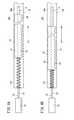
また、上述した蛇腹状の保護体58を設ける代わりに、図4A及び図4Bに示されるステントデリバリーシステム100のように螺旋状の保護体102を用いるようにしてもよいし、図5A及び図5Bに示されるステントデリバリーシステム110のように、例えば、中実筒状に形成された保護体112を用いるようにしてもよい。 Further, instead of providing the above-described bellows-like
この第1変形例に係る保護体102は、例えば、樹脂製材料からなる線材を螺旋状に巻回することによって形成され、軸方向(矢印A、B方向)に伸縮自在に形成される。なお、保護体102の材質及び形状は、ラック部材36が基端側(矢印A方向)へと移動する際の推力に対して前記保護体102の弾性力が小さくなるものが選択される。そして、保護体102の先端が、ラック部材36の基端に当接し、前記保護体102の基端が、収納溝46bにおける基端の内壁面に当接するように配置される。 The
そして、図4Aに示される状態からラック部材36が基端側(矢印A方向)へと移動することにより、該ラック部材36の基端によって押圧された保護体102が徐々に基端側(矢印A方向)へと押し潰されるように圧縮されていくと共に、その内部に挿通された内側チューブ体12の第1基端チューブ22の変形が前記保護体102の内周面によって規制され、該内側チューブ体12の変形(座屈)が確実に防止される。これにより、内側チューブ体12の座屈等の変形に起因した外側チューブ体14の動作不良が防止され、ステント16を生体管腔内の所望部位に確実に留置することが可能である。 Then, the
また、第2変形例に係る保護体112は、例えば、樹脂製材料から円柱状に形成され、その先端がラック部材36の基端に当接し、基端が収納溝46bにおける基端の内壁面に当接するように設けられる。保護体112は、軸方向(矢印A、B方向)に伸縮自在に設けられ、該軸方向に圧縮されることで拡径自在に形成される。保護体112の材質は、ラック部材36が基端側(矢印A方向)へと移動する際の推力に対して前記保護体112の弾性力が小さくなるものが選択され、具体的には、スポンジ、ゴム、ウレタン等が好適である。 Further, the
また、保護体112の中心部には、軸方向に沿って内側チューブ体12の第1基端チューブ22が挿通されている。 Further, the
そして、図5Aに示される状態からラック部材36が基端側(矢印A方向)へと移動することにより、該ラック部材36の基端によって押圧された保護体112が徐々に基端側(矢印A方向)へと押し潰されていくのと同時に、半径外方向へと徐々に拡径していく。これにより、保護体112の内部に挿通された内側チューブ体12の変形が前記保護体112によって規制され、該内側チューブ体12の座屈が確実に防止される。これにより、内側チューブ体12の座屈等の変形による外側チューブ体14の動作不良が防止され、ステント16を生体管腔内の所望部位に確実に留置することが可能である。 Then, as the
一方、上述した保護体58の代わりに、図6A及び図6Bに示されるステントデリバリーシステム120のように、内側チューブ体12の基端と外側チューブ体14の基端との間に設けられた2つの第1及び第2スライド部材122、124により形成される保護体126、より具体的には、ラック部材36の基端に連結された第1スライド部材122と、収納溝46bの基端に連結された第2スライド部材124とからなる保護体126を用いるようにしてもよい。 On the other hand, instead of the
この第3変形例に係る保護体126は、第1及び第2スライド部材122、124が、例えば、樹脂製材料からブロック状に形成され、前記第1スライド部材122は、内側チューブ体12に対して上方に配置され、前記第2スライド部材124は、前記内側チューブ体12に対して下方に配置される。 In the
第1スライド部材122の下面には、ラック部材36から離間する方向(基端側)に向かって徐々に上方へと傾斜した第1傾斜面128を有し、該第1傾斜面128の中央には内側チューブ体12の挿通される第1溝部130が一直線上に形成される。なお、第1溝部130は、第1スライド部材122の長手方向(矢印A、B方向)に沿って形成される。 The lower surface of the
第2スライド部材124の上面には、ラック部材36側(先端側)に向かって徐々に下方へと傾斜した第2傾斜面132を有し、該第2傾斜面132の中央には内側チューブ体12の挿通される第2溝部134が一直線上に形成される。なお、第2溝部134は、第2スライド部材124の長手方向(矢印A、B方向)に沿って形成される。また、第2傾斜面132の傾斜角度は、第1傾斜面128の傾斜角度と略同一に設定される。 The upper surface of the
そして、ステントデリバリーシステム120において、ステント16が外側チューブ体14の内部に収納された状態では、図6Aに示されるように、第1スライド部材122の基端と第2スライド部材124の先端とが軸方向に所定長さだけ重なるように配置され、且つ、ラック部材36の基端と収納溝46bの基端との間における内側チューブ体12の一部が第1スライド部材122の第1溝部130によって保持され、残りの内側チューブ体12が第2スライド部材124の第2溝部134によって保持される。 In the
このステントデリバリーシステム120において、図6Aに示される状態からラック部材36が基端側(矢印A方向)へと移動することにより、該ラック部材36の基端によって押圧された第1スライド部材122が徐々に第2スライド部材124側(矢印A方向)へと移動し、それに伴って、第1傾斜面128と第2傾斜面132とが徐々に接近していく。そして、第1スライド部材122が第2スライド部材124の上方へと移動することで、内側チューブ体12が前記第1及び第2スライド部材122、124によって上下から保持された状態となる。 In this
すなわち、ラック部材36の基端と収納溝46bの基端との間における内側チューブ体12が、保護体126を構成する第1スライド部材122及び第2スライド部材124の少なくともいずれかによって保持されているため、前記ラック部材36の移動に伴って内側チューブ体12に応力が付与された場合でも、前記内側チューブ体12の変形が前記保護体126によって規制され、該内側チューブ体12の座屈が確実に防止される。これにより、内側チューブ体12の変形による外側チューブ体14の動作不良が防止され、ステント16を生体管腔内の所望部位に確実に留置することが可能である。 That is, the
なお、上述したステントデリバリーシステム10、100、110、120にでは、保護体58、102、112、126の先端をラック部材36の基端に当接させ、該ラック部材36を基端側(矢印A方向)へと移動させる際に前記保護体58、102、112、126を押圧する構成としているが、これに限定されるものではなく、例えば、前記ラック部材36の基端側(矢印A方向)にさらにラック部材36に固定された別部材(連結体)を設け、前記別部材と収納溝46bとの間に保護体58、102、112、126を設けるようにしてもよい。 In the
また、上述した説明においては、回転ローラ40を回転させることでラック部材36をハウジング34の軸方向(矢印A、B方向)に沿って移動可能な構成としているが、例えば、前記回転ローラ40を設ける代わりに、前記ハウジング34の外部に露出し、且つ、前記ラック部材36又は前記別部材に連結された操作レバーを設け、前記操作レバーを直線的に動かすことで前記ラック部材36又は前記別部材を移動可能な構成としてもよい。 In the above description, the
なお、本発明に係るステントデリバリーシステムは、上述の実施の形態に限らず、本発明の要旨を逸脱することなく、種々の構成を採り得ることはもちろんである。 It should be noted that the stent delivery system according to the present invention is not limited to the above-described embodiment, and it is needless to say that various configurations can be adopted without departing from the gist of the present invention.
Claims (9)
Translated fromJapanese前記操作部(18)は、ハウジング(34)と、該ハウジング(34)の内部に収納された前記外管(14)に接続される連結体(36)と、を備え、前記ハウジング(34)の内部には、前記連結体(36)が軸方向に移動可能に保持される収納溝(46a、46b)が設けられ、前記連結体(36)の基端と前記収納溝(46a、46b)の基端との間に、該内管(12)の外周側を保護する保護体(58、102、112、126)が設けられることを特徴とするステントデリバリーシステム。The inner tube (12) is compressed in the direction of the central axis when inserted into the body lumen and disposed on the distal end side of the inner tube (12), and is expanded outwardly when placed in the body lumen so as to have a shape before compression. A stent (16) that can be restored and disposed on the outer surface side of the inner tube (12) so that the stent (16) can be accommodated in a lumen, and is proximal to the inner tube (12). An outer tube (14) capable of releasing the stent (16) to the outside by moving in the direction, and an operation unit for moving the outer tube (14) in the axial direction relative to the inner tube (12) (18) a stent delivery system (10, 100, 110, 120) comprising:
The operation section (18) includes a housing (34)and a coupling body (36) connected to the outer pipe (14) housed in the housing (34), and the housing (34). A housing groove (46a, 46b) for holding the coupling body (36) so as to be movable in the axial direction is provided inside the base body, and a base end of the coupling body (36) and the housing groove (46a, 46b). A stent delivery system, wherein a protective body (58, 102, 112, 126) for protecting the outer peripheral side of the inner tube (12) is provided betweenthe proximal end of the inner tube (12).
前記保護体(58、102、112)は、前記内管(12)の外周側を覆っていることを特徴とするステントデリバリーシステム。The stent delivery system according to claim 1, wherein
The stent delivery system, wherein the protective body (58, 102, 112) covers an outer peripheral side of the inner tube (12).
前記保護体(58、102、112)は、前記外管(14)の軸方向に沿った移動に追従して該軸方向に変形自在に設けられることを特徴とするステントデリバリーシステム。The stent delivery system according to claim 1 or 2,
The stent delivery system, wherein the protector (58, 102, 112) is provided to be deformable in the axial direction following the movement of the outer tube (14) along the axial direction.
前記保護体(58、102、112)の弾性力は、少なくとも前記外管(14)が基端側へと移動する際の推力に対して小さく設定されることを特徴とするステントデリバリーシステム。The stent delivery system according to any one of claims 1 to 3,
Elastic force, stent delivery systems, wherein at least the outer tube (14) is set smaller than the thrust in moving toward the proximal end side of the protective member (58,102,112).
前記保護体(58、102、112、126)は、前記外管(14)、又は、該外管(14)が連結される連結体(36)によって基端側へと押圧されることを特徴とするステントデリバリーシステム。In the stent delivery system according to any one of claims 1 to 4,
The protective body (58, 102, 112, 126) is pressed toward the base end side by the outer pipe (14) or a connecting body (36) to which the outer pipe (14) is connected. And stent delivery system.
前記保護体(58)は、前記軸方向に折り畳み自在な蛇腹状の筒体からなることを特徴とするステントデリバリーシステム。In the stent delivery system according to any one of claims 1 to 5,
The stent delivery system according to claim 1, wherein the protective body (58) is formed of a bellows-like cylindrical body that can be folded in the axial direction.
前記保護体(102)は、前記軸方向に沿って螺旋状に形成されることを特徴とするステントデリバリーシステム。In the stent delivery system according to any one of claims 1 to 5,
The stent delivery system according to claim 1, wherein the protective body (102) is formed in a spiral shape along the axial direction.
前記保護体(112)は、円柱状に形成されていることを特徴とするステントデリバリーシステム。In the stent delivery system according to any one of claims 1 to 5,
The protector (112) is formed in a columnar shape, wherein the stent delivery system.
前記保護体(126)は、前記内管(12)の基端と前記外管(14)の基端との間に設けられた2つのスライド部材(122、124)により形成されていることを特徴とするステントデリバリーシステム。According to claim 1or 5 SL placement of the stent delivery system,
The protective body (126) is formed by two slide members (122, 124) provided between the proximal end of the inner tube (12) and the proximal end of the outer tube (14). A featured stent delivery system.
Priority Applications (1)
| Application Number | Priority Date | Filing Date | Title |
|---|---|---|---|
| JP2014500121AJP6163478B2 (en) | 2012-02-15 | 2013-01-15 | Stent delivery system |
Applications Claiming Priority (4)
| Application Number | Priority Date | Filing Date | Title |
|---|---|---|---|
| JP2012030027 | 2012-02-15 | ||
| JP2012030027 | 2012-02-15 | ||
| JP2014500121AJP6163478B2 (en) | 2012-02-15 | 2013-01-15 | Stent delivery system |
| PCT/JP2013/050551WO2013121811A1 (en) | 2012-02-15 | 2013-01-15 | Stent delivery system |
Publications (2)
| Publication Number | Publication Date |
|---|---|
| JPWO2013121811A1 JPWO2013121811A1 (en) | 2015-05-11 |
| JP6163478B2true JP6163478B2 (en) | 2017-07-12 |
Family
ID=48983937
Family Applications (1)
| Application Number | Title | Priority Date | Filing Date |
|---|---|---|---|
| JP2014500121AActiveJP6163478B2 (en) | 2012-02-15 | 2013-01-15 | Stent delivery system |
Country Status (3)
| Country | Link |
|---|---|
| US (1) | US9707115B2 (en) |
| JP (1) | JP6163478B2 (en) |
| WO (1) | WO2013121811A1 (en) |
Families Citing this family (17)
| Publication number | Priority date | Publication date | Assignee | Title |
|---|---|---|---|---|
| US8128677B2 (en) | 2007-12-12 | 2012-03-06 | Intact Vascular LLC | Device and method for tacking plaque to a blood vessel wall |
| US10166127B2 (en) | 2007-12-12 | 2019-01-01 | Intact Vascular, Inc. | Endoluminal device and method |
| US7896911B2 (en) | 2007-12-12 | 2011-03-01 | Innovasc Llc | Device and method for tacking plaque to blood vessel wall |
| US10022250B2 (en) | 2007-12-12 | 2018-07-17 | Intact Vascular, Inc. | Deployment device for placement of multiple intraluminal surgical staples |
| US10285831B2 (en) | 2011-06-03 | 2019-05-14 | Intact Vascular, Inc. | Endovascular implant |
| US9050067B2 (en)* | 2011-09-26 | 2015-06-09 | Cook Medical Technologies, LLC | Percutaneous nephrostomy plug delivery device |
| WO2015012007A1 (en)* | 2013-07-22 | 2015-01-29 | テルモ株式会社 | Stent delivery system |
| US9375336B1 (en) | 2015-01-29 | 2016-06-28 | Intact Vascular, Inc. | Delivery device and method of delivery |
| US9433520B2 (en) | 2015-01-29 | 2016-09-06 | Intact Vascular, Inc. | Delivery device and method of delivery |
| US10993824B2 (en) | 2016-01-01 | 2021-05-04 | Intact Vascular, Inc. | Delivery device and method of delivery |
| US20170252025A1 (en)* | 2016-03-01 | 2017-09-07 | Oz Cabiri | Steering tool with controlled distal flexibility |
| US11660218B2 (en) | 2017-07-26 | 2023-05-30 | Intact Vascular, Inc. | Delivery device and method of delivery |
| US10441449B1 (en) | 2018-05-30 | 2019-10-15 | Vesper Medical, Inc. | Rotary handle stent delivery system and method |
| US10449073B1 (en) | 2018-09-18 | 2019-10-22 | Vesper Medical, Inc. | Rotary handle stent delivery system and method |
| CN109481110B (en)* | 2018-12-29 | 2024-02-02 | 上海拓脉医疗科技有限公司 | Delivery system for medical implants |
| US11219541B2 (en) | 2020-05-21 | 2022-01-11 | Vesper Medical, Inc. | Wheel lock for thumbwheel actuated device |
| CN116490152A (en)* | 2020-10-13 | 2023-07-25 | 俄勒冈健康与科学大学 | Auxetic device conveying equipment and method |
Family Cites Families (34)
| Publication number | Priority date | Publication date | Assignee | Title |
|---|---|---|---|---|
| US4106508A (en)* | 1976-08-31 | 1978-08-15 | Richard Barnard Berlin | Clamp device |
| US6206888B1 (en)* | 1997-10-01 | 2001-03-27 | Scimed Life Systems, Inc. | Stent delivery system using shape memory retraction |
| EP1447057A1 (en)* | 1998-09-30 | 2004-08-18 | Bard Peripheral Vascular, Inc. | Delivery mechanism for implantable stent |
| US7025773B2 (en)* | 1999-01-15 | 2006-04-11 | Medtronic, Inc. | Methods and devices for placing a conduit in fluid communication with a target vessel |
| US7578828B2 (en)* | 1999-01-15 | 2009-08-25 | Medtronic, Inc. | Methods and devices for placing a conduit in fluid communication with a target vessel |
| US8702727B1 (en)* | 1999-02-01 | 2014-04-22 | Hologic, Inc. | Delivery catheter with implant ejection mechanism |
| US6899727B2 (en) | 2001-01-22 | 2005-05-31 | Gore Enterprise Holdings, Inc. | Deployment system for intraluminal devices |
| US6599296B1 (en)* | 2001-07-27 | 2003-07-29 | Advanced Cardiovascular Systems, Inc. | Ratcheting handle for intraluminal catheter systems |
| US6755854B2 (en)* | 2001-07-31 | 2004-06-29 | Advanced Cardiovascular Systems, Inc. | Control device and mechanism for deploying a self-expanding medical device |
| US7052511B2 (en)* | 2002-04-04 | 2006-05-30 | Scimed Life Systems, Inc. | Delivery system and method for deployment of foreshortening endoluminal devices |
| US20040006380A1 (en)* | 2002-07-05 | 2004-01-08 | Buck Jerrick C. | Stent delivery system |
| US20050261719A1 (en) | 2002-11-25 | 2005-11-24 | Israel Chermoni | Catheter and method of its use |
| US7780716B2 (en)* | 2003-09-02 | 2010-08-24 | Abbott Laboratories | Delivery system for a medical device |
| US7794489B2 (en)* | 2003-09-02 | 2010-09-14 | Abbott Laboratories | Delivery system for a medical device |
| US7967829B2 (en)* | 2003-10-09 | 2011-06-28 | Boston Scientific Scimed, Inc. | Medical device delivery system |
| US7635382B2 (en)* | 2003-10-22 | 2009-12-22 | Medtronic Vascular, Inc. | Delivery system for long self-expanding stents |
| WO2005115524A2 (en)* | 2003-11-25 | 2005-12-08 | F.D. Cardio Ltd. | Catheter drive |
| US7326236B2 (en)* | 2003-12-23 | 2008-02-05 | Xtent, Inc. | Devices and methods for controlling and indicating the length of an interventional element |
| US20070156225A1 (en)* | 2003-12-23 | 2007-07-05 | Xtent, Inc. | Automated control mechanisms and methods for custom length stent apparatus |
| US7766952B2 (en)* | 2005-06-07 | 2010-08-03 | Salviac Limited | Deployment system for a medical device |
| WO2007005799A1 (en)* | 2005-06-30 | 2007-01-11 | Abbott Laboratories | Delivery system for a medical device |
| IL170698A (en)* | 2005-09-06 | 2011-11-30 | Allium Ltd | System for delivering a medical device to a body location |
| ES2382364T3 (en)* | 2006-09-28 | 2012-06-07 | St George Medical Inc | Thoracic aortic aneurysm repair device. |
| EP2328524B1 (en)* | 2008-07-02 | 2019-01-16 | Cook Medical Technologies LLC | Deployment assembly |
| US7976574B2 (en)* | 2008-08-08 | 2011-07-12 | Advanced Cardiovascular Systems, Inc. | Delivery system with variable delivery rate for deploying a medical device |
| US8888833B2 (en)* | 2008-11-14 | 2014-11-18 | Abbott Cardiovascular Systems Inc. | Delivery system having one piece inner member with flat distal end portion |
| JP5767114B2 (en)* | 2009-12-28 | 2015-08-19 | テルモ株式会社 | Stent delivery system |
| WO2011122444A1 (en)* | 2010-03-30 | 2011-10-06 | テルモ株式会社 | Stent delivery system |
| EP2682075A4 (en)* | 2011-03-03 | 2014-09-10 | Terumo Corp | Stent delivery system |
| PL2724690T3 (en)* | 2011-06-01 | 2017-01-31 | Nvt Ag | Cardiac valve prosthesis deployment system |
| US8852258B2 (en)* | 2011-10-24 | 2014-10-07 | Novostent Corporation | Catheter assembly with user-assisting handle |
| US9662235B2 (en)* | 2012-04-04 | 2017-05-30 | Boston Scientific Scimed, Inc. | Handle for delivering medical device |
| EP3583927B1 (en)* | 2014-03-24 | 2023-11-08 | Boston Scientific Scimed, Inc. | Self-expanding stent delivery system |
| US9192500B1 (en)* | 2015-01-29 | 2015-11-24 | Intact Vascular, Inc. | Delivery device and method of delivery |
- 2013
- 2013-01-15JPJP2014500121Apatent/JP6163478B2/enactiveActive
- 2013-01-15WOPCT/JP2013/050551patent/WO2013121811A1/enactiveApplication Filing
- 2014
- 2014-05-23USUS14/286,356patent/US9707115B2/ennot_activeExpired - Fee Related
Also Published As
| Publication number | Publication date |
|---|---|
| US20140257459A1 (en) | 2014-09-11 |
| JPWO2013121811A1 (en) | 2015-05-11 |
| US9707115B2 (en) | 2017-07-18 |
| WO2013121811A1 (en) | 2013-08-22 |
Similar Documents
| Publication | Publication Date | Title |
|---|---|---|
| JP6163478B2 (en) | Stent delivery system | |
| JP5907946B2 (en) | Stent delivery system | |
| JP5829266B2 (en) | Stent delivery system | |
| JP5829263B2 (en) | Stent delivery system | |
| US11426192B2 (en) | Catheter for removing foreign body in blood vessel | |
| JP6151683B2 (en) | Stent delivery system | |
| WO2011122444A1 (en) | Stent delivery system | |
| ES2649548T3 (en) | Implant delivery system with mutually locked RX port orientation | |
| JP2012501725A5 (en) | ||
| RU2016125324A (en) | BASIC STENT DELIVERY SYSTEM ASSEMBLY | |
| WO2008063496A2 (en) | Delivery system catheter with rotating distal end | |
| JP5795718B2 (en) | Stent delivery system | |
| JP2012005705A (en) | Balloon catheter | |
| CN105640680A (en) | Stent delivery system | |
| CN113057719B (en) | Balloon catheter | |
| CN107518968A (en) | Self-expanding stent induction system and its gear drive component | |
| WO2014109048A1 (en) | Medical device for biological lumen | |
| WO2018008515A1 (en) | Balloon catheter | |
| CN108245291A (en) | Self-expanding stent transport system and its conduit tube component | |
| WO2016186032A1 (en) | Endoscopic treatment instrument | |
| WO2013125333A1 (en) | Stent delivery system | |
| JP7357047B2 (en) | Balloon catheter and balloon placement method | |
| JP2016067371A (en) | Housing tool | |
| JP2013223662A (en) | Balloon catheter system and stent delivery system | |
| JP7387098B2 (en) | stent delivery catheter |
Legal Events
| Date | Code | Title | Description |
|---|---|---|---|
| A621 | Written request for application examination | Free format text:JAPANESE INTERMEDIATE CODE: A621 Effective date:20151207 | |
| A131 | Notification of reasons for refusal | Free format text:JAPANESE INTERMEDIATE CODE: A131 Effective date:20161004 | |
| A521 | Request for written amendment filed | Free format text:JAPANESE INTERMEDIATE CODE: A523 Effective date:20161201 | |
| TRDD | Decision of grant or rejection written | ||
| A01 | Written decision to grant a patent or to grant a registration (utility model) | Free format text:JAPANESE INTERMEDIATE CODE: A01 Effective date:20170530 | |
| A61 | First payment of annual fees (during grant procedure) | Free format text:JAPANESE INTERMEDIATE CODE: A61 Effective date:20170619 | |
| R150 | Certificate of patent or registration of utility model | Ref document number:6163478 Country of ref document:JP Free format text:JAPANESE INTERMEDIATE CODE: R150 | |
| R250 | Receipt of annual fees | Free format text:JAPANESE INTERMEDIATE CODE: R250 | |
| R250 | Receipt of annual fees | Free format text:JAPANESE INTERMEDIATE CODE: R250 | |
| R250 | Receipt of annual fees | Free format text:JAPANESE INTERMEDIATE CODE: R250 | |
| R250 | Receipt of annual fees | Free format text:JAPANESE INTERMEDIATE CODE: R250 | |
| R250 | Receipt of annual fees | Free format text:JAPANESE INTERMEDIATE CODE: R250 |