JP6160504B2 - Power receiving device - Google Patents
Power receiving deviceDownload PDFInfo
- Publication number
- JP6160504B2 JP6160504B2JP2014030568AJP2014030568AJP6160504B2JP 6160504 B2JP6160504 B2JP 6160504B2JP 2014030568 AJP2014030568 AJP 2014030568AJP 2014030568 AJP2014030568 AJP 2014030568AJP 6160504 B2JP6160504 B2JP 6160504B2
- Authority
- JP
- Japan
- Prior art keywords
- power
- unit
- relay
- capacitor
- current
- Prior art date
- Legal status (The legal status is an assumption and is not a legal conclusion. Google has not performed a legal analysis and makes no representation as to the accuracy of the status listed.)
- Active
Links
Images


Classifications
- H02J7/025—
- B—PERFORMING OPERATIONS; TRANSPORTING
- B60—VEHICLES IN GENERAL
- B60L—PROPULSION OF ELECTRICALLY-PROPELLED VEHICLES; SUPPLYING ELECTRIC POWER FOR AUXILIARY EQUIPMENT OF ELECTRICALLY-PROPELLED VEHICLES; ELECTRODYNAMIC BRAKE SYSTEMS FOR VEHICLES IN GENERAL; MAGNETIC SUSPENSION OR LEVITATION FOR VEHICLES; MONITORING OPERATING VARIABLES OF ELECTRICALLY-PROPELLED VEHICLES; ELECTRIC SAFETY DEVICES FOR ELECTRICALLY-PROPELLED VEHICLES
- B60L53/00—Methods of charging batteries, specially adapted for electric vehicles; Charging stations or on-board charging equipment therefor; Exchange of energy storage elements in electric vehicles
- B60L53/10—Methods of charging batteries, specially adapted for electric vehicles; Charging stations or on-board charging equipment therefor; Exchange of energy storage elements in electric vehicles characterised by the energy transfer between the charging station and the vehicle
- B60L53/12—Inductive energy transfer
- H—ELECTRICITY
- H02—GENERATION; CONVERSION OR DISTRIBUTION OF ELECTRIC POWER
- H02J—CIRCUIT ARRANGEMENTS OR SYSTEMS FOR SUPPLYING OR DISTRIBUTING ELECTRIC POWER; SYSTEMS FOR STORING ELECTRIC ENERGY
- H02J50/00—Circuit arrangements or systems for wireless supply or distribution of electric power
- H02J50/10—Circuit arrangements or systems for wireless supply or distribution of electric power using inductive coupling
- H02J50/12—Circuit arrangements or systems for wireless supply or distribution of electric power using inductive coupling of the resonant type
- H—ELECTRICITY
- H02—GENERATION; CONVERSION OR DISTRIBUTION OF ELECTRIC POWER
- H02J—CIRCUIT ARRANGEMENTS OR SYSTEMS FOR SUPPLYING OR DISTRIBUTING ELECTRIC POWER; SYSTEMS FOR STORING ELECTRIC ENERGY
- H02J50/00—Circuit arrangements or systems for wireless supply or distribution of electric power
- H02J50/70—Circuit arrangements or systems for wireless supply or distribution of electric power involving the reduction of electric, magnetic or electromagnetic leakage fields
- H—ELECTRICITY
- H02—GENERATION; CONVERSION OR DISTRIBUTION OF ELECTRIC POWER
- H02J—CIRCUIT ARRANGEMENTS OR SYSTEMS FOR SUPPLYING OR DISTRIBUTING ELECTRIC POWER; SYSTEMS FOR STORING ELECTRIC ENERGY
- H02J50/00—Circuit arrangements or systems for wireless supply or distribution of electric power
- H02J50/80—Circuit arrangements or systems for wireless supply or distribution of electric power involving the exchange of data, concerning supply or distribution of electric power, between transmitting devices and receiving devices
- H—ELECTRICITY
- H02—GENERATION; CONVERSION OR DISTRIBUTION OF ELECTRIC POWER
- H02J—CIRCUIT ARRANGEMENTS OR SYSTEMS FOR SUPPLYING OR DISTRIBUTING ELECTRIC POWER; SYSTEMS FOR STORING ELECTRIC ENERGY
- H02J7/00—Circuit arrangements for charging or depolarising batteries or for supplying loads from batteries
- H02J7/34—Parallel operation in networks using both storage and other DC sources, e.g. providing buffering
- H02J7/345—Parallel operation in networks using both storage and other DC sources, e.g. providing buffering using capacitors as storage or buffering devices
- Y—GENERAL TAGGING OF NEW TECHNOLOGICAL DEVELOPMENTS; GENERAL TAGGING OF CROSS-SECTIONAL TECHNOLOGIES SPANNING OVER SEVERAL SECTIONS OF THE IPC; TECHNICAL SUBJECTS COVERED BY FORMER USPC CROSS-REFERENCE ART COLLECTIONS [XRACs] AND DIGESTS
- Y02—TECHNOLOGIES OR APPLICATIONS FOR MITIGATION OR ADAPTATION AGAINST CLIMATE CHANGE
- Y02T—CLIMATE CHANGE MITIGATION TECHNOLOGIES RELATED TO TRANSPORTATION
- Y02T10/00—Road transport of goods or passengers
- Y02T10/60—Other road transportation technologies with climate change mitigation effect
- Y02T10/70—Energy storage systems for electromobility, e.g. batteries
- Y—GENERAL TAGGING OF NEW TECHNOLOGICAL DEVELOPMENTS; GENERAL TAGGING OF CROSS-SECTIONAL TECHNOLOGIES SPANNING OVER SEVERAL SECTIONS OF THE IPC; TECHNICAL SUBJECTS COVERED BY FORMER USPC CROSS-REFERENCE ART COLLECTIONS [XRACs] AND DIGESTS
- Y02—TECHNOLOGIES OR APPLICATIONS FOR MITIGATION OR ADAPTATION AGAINST CLIMATE CHANGE
- Y02T—CLIMATE CHANGE MITIGATION TECHNOLOGIES RELATED TO TRANSPORTATION
- Y02T10/00—Road transport of goods or passengers
- Y02T10/60—Other road transportation technologies with climate change mitigation effect
- Y02T10/7072—Electromobility specific charging systems or methods for batteries, ultracapacitors, supercapacitors or double-layer capacitors
- Y—GENERAL TAGGING OF NEW TECHNOLOGICAL DEVELOPMENTS; GENERAL TAGGING OF CROSS-SECTIONAL TECHNOLOGIES SPANNING OVER SEVERAL SECTIONS OF THE IPC; TECHNICAL SUBJECTS COVERED BY FORMER USPC CROSS-REFERENCE ART COLLECTIONS [XRACs] AND DIGESTS
- Y02—TECHNOLOGIES OR APPLICATIONS FOR MITIGATION OR ADAPTATION AGAINST CLIMATE CHANGE
- Y02T—CLIMATE CHANGE MITIGATION TECHNOLOGIES RELATED TO TRANSPORTATION
- Y02T90/00—Enabling technologies or technologies with a potential or indirect contribution to GHG emissions mitigation
- Y02T90/10—Technologies relating to charging of electric vehicles
- Y02T90/12—Electric charging stations
- Y—GENERAL TAGGING OF NEW TECHNOLOGICAL DEVELOPMENTS; GENERAL TAGGING OF CROSS-SECTIONAL TECHNOLOGIES SPANNING OVER SEVERAL SECTIONS OF THE IPC; TECHNICAL SUBJECTS COVERED BY FORMER USPC CROSS-REFERENCE ART COLLECTIONS [XRACs] AND DIGESTS
- Y02—TECHNOLOGIES OR APPLICATIONS FOR MITIGATION OR ADAPTATION AGAINST CLIMATE CHANGE
- Y02T—CLIMATE CHANGE MITIGATION TECHNOLOGIES RELATED TO TRANSPORTATION
- Y02T90/00—Enabling technologies or technologies with a potential or indirect contribution to GHG emissions mitigation
- Y02T90/10—Technologies relating to charging of electric vehicles
- Y02T90/14—Plug-in electric vehicles
Landscapes
- Engineering & Computer Science (AREA)
- Power Engineering (AREA)
- Computer Networks & Wireless Communication (AREA)
- Physics & Mathematics (AREA)
- Electromagnetism (AREA)
- Transportation (AREA)
- Mechanical Engineering (AREA)
- Charge And Discharge Circuits For Batteries Or The Like (AREA)
- Electric Propulsion And Braking For Vehicles (AREA)
- Protection Of Static Devices (AREA)
- Current-Collector Devices For Electrically Propelled Vehicles (AREA)
Description
Translated fromJapaneseこの発明は、受電装置に関し、特に、送電装置から出力される電力を非接触で受電する受電装置に関する。 The present invention relates to a power receiving device, and more particularly to a power receiving device that receives power output from a power transmitting device in a contactless manner.
送電装置から受電装置へ非接触で電力を伝送する電力伝送システムが注目されている。特開2013−169132号公報は、そのような受電装置を搭載した電動車両を開示する。受電装置は、コイルおよびキャパシタから成る受電部(共振器)を含む。また、受電装置は、受電部(共振器)以外にも、整流器やフィルタ等の機器ユニットと、受電電圧や受電電流を検出するセンサユニットとをさらに含む(特許文献1参照)。 Attention has been focused on power transmission systems that transmit power from a power transmission device to a power reception device in a contactless manner. Japanese Patent Laying-Open No. 2013-169132 discloses an electric vehicle equipped with such a power receiving device. The power reception device includes a power reception unit (resonator) including a coil and a capacitor. In addition to the power receiving unit (resonator), the power receiving device further includes a device unit such as a rectifier and a filter, and a sensor unit that detects a received voltage or a received current (see Patent Document 1).
上記のように、受電装置は、受電部(共振器)とともに整流器やフィルタ等の機器ユニットを含むところ、上記の特許文献1では、種々の機器を含む受電装置の異常有無を検知するための手法については、特に検討されていない。受電装置が送電装置から受電しているときの受電電圧や受電電流の検出値に基づいて受電装置の異常を検知し得るかもしれないが、送電装置の存否に拘わらず受電装置単独(車両単独)で受電装置の異常有無を検知可能とすることが望まれる。 As described above, the power receiving device includes device units such as a rectifier and a filter together with the power receiving unit (resonator). In Patent Document 1, a method for detecting the presence / absence of abnormality of the power receiving device including various devices is described. No particular consideration has been given to. Although the power receiving device may be able to detect an abnormality in the power receiving device based on the detected value of the power receiving voltage or current when the power receiving device is receiving power from the power transmitting device, the power receiving device alone (vehicle alone) regardless of the presence or absence of the power transmitting device Therefore, it is desirable to be able to detect whether there is an abnormality in the power receiving device.
また、受電装置には、複数のキャパシタおよび複数のコイルが一般的に含まれており、キャパシタの異常(たとえば経年劣化)とともにコイルの異常(たとえばコアの割れ等)も検知可能とすることが望ましい。 In addition, the power receiving device generally includes a plurality of capacitors and a plurality of coils, and it is desirable to be able to detect abnormality of the coil (for example, cracking of the core, etc.) as well as abnormality of the capacitor (for example, deterioration over time). .
それゆえに、この発明の目的は、送電装置から出力される電力を非接触で受電する受電装置において、受電装置単独で受電装置の異常有無を検知可能とし、かつ、キャパシタとともにコイルの異常も検知可能とすることである。 SUMMARY OF THE INVENTION Therefore, an object of the present invention is to make it possible to detect the presence or absence of abnormality of a power receiving device by the power receiving device alone, and to detect abnormality of a coil together with a capacitor, in a power receiving device that receives power output from the power transmitting device in a contactless manner. It is to do.
この発明によれば、受電装置は、モジュールと、第1リレーと、交流電源部と、電流センサと、制御装置とを備える。モジュールは、受電部と、機器ユニットとを含む。受電部は、送電装置から出力される電力を非接触で受電する。機器ユニットは、受電部と、受電部により受電された電力を蓄える蓄電装置との間に設けられる。第1リレーは、機器ユニットと蓄電装置との間に設けられる。交流電源部は、第1リレーよりも受電部側に設けられる電力線に交流電流を供給可能に構成される。電流センサは、上記電力線の電流を検出する。モジュールは、コイルとキャパシタとを含む。制御装置は、第1リレーが電力遮断状態である場合に交流電源部から上記電力線に交流電流が供給されているとき、電流センサの検出値に基づいてコイルおよびキャパシタの少なくとも一方に異常が生じているか否かを検知する。 According to the present invention, the power receiving device includes a module, a first relay, an AC power supply unit, a current sensor, and a control device. The module includes a power reception unit and a device unit. The power receiving unit receives the power output from the power transmission device in a contactless manner. The device unit is provided between the power receiving unit and the power storage device that stores the power received by the power receiving unit. The first relay is provided between the device unit and the power storage device. The AC power supply unit is configured to be able to supply an AC current to a power line provided closer to the power receiving unit than the first relay. The current sensor detects the current of the power line. The module includes a coil and a capacitor. When the AC relay is supplied from the AC power supply unit to the power line when the first relay is in a power cut-off state, the control device has an abnormality in at least one of the coil and the capacitor based on the detection value of the current sensor. Detect whether or not.
この受電装置においては、第1リレーよりも受電部側に設けられる電力線に交流電流を供給可能な交流電源部が設けられる。そして、交流電源部が交流電流を供給することによって、送電装置からの受電中でなくても受電装置単独で受電装置の異常有無を検知し得る。また、交流電源部によって交流電流が供給されるので、コイルのインピーダンスの変化に基づきコイルの異常を検知し得る。したがって、この受電装置によれば、受電装置単独で受電装置の異常有無を検知することができ、かつ、キャパシタとともにコイルの異常も検知することができる。 In this power receiving apparatus, an AC power supply unit that can supply an AC current to a power line provided closer to the power receiving unit than the first relay is provided. Then, by supplying an alternating current from the AC power supply unit, it is possible to detect whether or not the power receiving device is abnormal by the power receiving device alone even when the power receiving device is not receiving power. Moreover, since an alternating current is supplied by the alternating current power supply unit, an abnormality of the coil can be detected based on a change in impedance of the coil. Therefore, according to this power receiving device, it is possible to detect the presence or absence of abnormality of the power receiving device alone and to detect abnormality of the coil together with the capacitor.
好ましくは、受電装置は、第2リレーをさらに備える。第2リレーは、受電部と機器ユニットとの間に設けられる。コイルは、機器ユニットに設けられる第1コイルを含む。キャパシタは、機器ユニットに設けられる第1キャパシタを含む。交流電源部は、第1リレーと第2リレーとの間に電気的に接続される。電流センサは、第1リレーと第2リレーとの間に設けられる電力線の電流を検出する。制御装置は、第1リレーおよび第2リレーが電力遮断状態である場合に交流電源部から交流電流が供給されているとき、電流センサの検出値に基づいて第1コイルおよび第1キャパシタの少なくとも一方に異常が生じているか否かを検知する。 Preferably, the power receiving device further includes a second relay. The second relay is provided between the power reception unit and the device unit. The coil includes a first coil provided in the device unit. The capacitor includes a first capacitor provided in the device unit. The AC power supply unit is electrically connected between the first relay and the second relay. The current sensor detects a current of a power line provided between the first relay and the second relay. When the first relay and the second relay are in a power cut-off state, the control device is configured to supply at least one of the first coil and the first capacitor based on a detection value of the current sensor when an AC current is supplied from the AC power supply unit. Whether or not an abnormality has occurred is detected.
この受電装置においては、第2リレーにより機器ユニットから受電部が電気的に切り離されて、機器ユニットの第1コイルおよび第1キャパシタの少なくとも一方に異常が生じているか否かが検知される。したがって、この受電装置によれば、受電部と区別して機器ユニットの異常有無を検知することができる。 In this power reception device, the power reception unit is electrically disconnected from the device unit by the second relay, and it is detected whether or not an abnormality has occurred in at least one of the first coil and the first capacitor of the device unit. Therefore, according to this power receiving device, it is possible to detect the presence / absence of an abnormality in the device unit in distinction from the power receiving unit.
さらに好ましくは、コイルは、受電部に設けられる第2コイルをさらに含む。キャパシタは、受電部に設けられる第2キャパシタをさらに含む。制御装置は、第1コイルおよび第1キャパシタに異常が生じていないことを検知した後、第2リレーを通電状態にして、電流センサの検出値に基づいて第2コイルおよび第2キャパシタの少なくとも一方に異常が生じているか否かを検知する。 More preferably, the coil further includes a second coil provided in the power receiving unit. The capacitor further includes a second capacitor provided in the power receiving unit. The control device detects that no abnormality has occurred in the first coil and the first capacitor, and then energizes the second relay, and based on the detection value of the current sensor, at least one of the second coil and the second capacitor. Whether or not an abnormality has occurred is detected.
この受電装置によれば、機器ユニットと区別して受電部の異常有無をさらに検知することができる。 According to this power receiving device, it is possible to further detect whether there is an abnormality in the power receiving unit in distinction from the device unit.
好ましくは、機器ユニットは、整流回路と、フィルタ回路とを含む。整流回路は、受電部により受電された電力を整流する。フィルタ回路は、受電部と整流回路との間に設けられる。第1コイルおよび第1キャパシタは、フィルタ回路に含まれる。キャパシタは、整流回路に設けられる第3キャパシタをさらに含む。電流センサは、第1電流センサと、第2電流センサとを含む。第1電流センサは、第2リレーと整流回路との間に設けられる電力線の電流を検出する。第2電流センサは、整流回路と第1リレーとの間の電力線の電流を検出する。交流電源部は、第2リレーとフィルタ回路との間の電力線に電気的に接続される。制御装置は、第1電流センサの検出値に基づいてフィルタ回路または受電部の異常有無を検知し、第2電流センサの検出値に基づいて整流回路の異常有無を検知する。 Preferably, the equipment unit includes a rectifier circuit and a filter circuit. The rectifier circuit rectifies the power received by the power receiving unit. The filter circuit is provided between the power reception unit and the rectifier circuit. The first coil and the first capacitor are included in the filter circuit. The capacitor further includes a third capacitor provided in the rectifier circuit. The current sensor includes a first current sensor and a second current sensor. The first current sensor detects a current of a power line provided between the second relay and the rectifier circuit. The second current sensor detects a current of the power line between the rectifier circuit and the first relay. The AC power supply unit is electrically connected to a power line between the second relay and the filter circuit. The control device detects whether the filter circuit or the power reception unit is abnormal based on the detection value of the first current sensor, and detects whether the rectifier circuit is abnormal based on the detection value of the second current sensor.
この受電装置においては、第2リレーが電力遮断状態であるとき、第1電流センサの検出値に基づいてフィルタ回路の異常有無を検知することができる。また、第2リレーが通電状態であるとき、第1電流センサの検出値に基づいて受電部の異常有無を検知することができる。さらに、第2電流センサの検出値に基づいて整流回路の異常有無を検知することができる。したがって、この受電装置によれば、フィルタ回路、受電部、および整流回路を区別して異常有無を検知することができる。 In this power receiving device, when the second relay is in the power cut-off state, it is possible to detect whether the filter circuit is abnormal based on the detection value of the first current sensor. Further, when the second relay is in the energized state, it is possible to detect the presence or absence of an abnormality in the power receiving unit based on the detection value of the first current sensor. Furthermore, it is possible to detect whether or not the rectifier circuit is abnormal based on the detection value of the second current sensor. Therefore, according to this power receiving device, it is possible to detect the presence or absence of abnormality by distinguishing the filter circuit, the power receiving unit, and the rectifier circuit.
また、好ましくは、機器ユニットは、整流回路と、フィルタ回路とを含む。整流回路は、受電部により受電された電力を整流する。フィルタ回路は、受電部と整流回路との間に設けられる。第1コイルおよび第1キャパシタは、フィルタ回路に含まれる。キャパシタは、整流回路に設けられる第3キャパシタをさらに含む。電流センサは、第1電流センサと、第2電流センサとを含む。第1電流センサは、第2リレーと整流回路との間に設けられる電力線の電流を検出する。第2電流センサは、整流回路と第1リレーとの間の電力線の電流を検出する。交流電源部は、フィルタ回路と整流回路との間の電力線に電気的に接続される。制御装置は、第1電流センサの検出値に基づいてフィルタ回路または受電部の異常有無を検知し、第2電流センサの検出値に基づいて整流回路の異常有無を検知する。 Preferably, the device unit includes a rectifier circuit and a filter circuit. The rectifier circuit rectifies the power received by the power receiving unit. The filter circuit is provided between the power reception unit and the rectifier circuit. The first coil and the first capacitor are included in the filter circuit. The capacitor further includes a third capacitor provided in the rectifier circuit. The current sensor includes a first current sensor and a second current sensor. The first current sensor detects a current of a power line provided between the second relay and the rectifier circuit. The second current sensor detects a current of the power line between the rectifier circuit and the first relay. The AC power supply unit is electrically connected to a power line between the filter circuit and the rectifier circuit. The control device detects whether the filter circuit or the power reception unit is abnormal based on the detection value of the first current sensor, and detects whether the rectifier circuit is abnormal based on the detection value of the second current sensor.
この受電装置によっても、フィルタ回路、受電部、および整流回路を区別して異常有無を検知することができる。 Also with this power receiving device, the presence or absence of abnormality can be detected by distinguishing the filter circuit, the power receiving unit, and the rectifier circuit.
また、好ましくは、機器ユニットは、整流回路と、フィルタ回路とを含む。整流回路は、受電部により受電された電力を整流する。フィルタ回路は、受電部と整流回路との間に設けられる。第1コイルおよび第1キャパシタは、フィルタ回路に含まれる。キャパシタは、整流回路の整流器の出力側に設けられる第3キャパシタをさらに含む。電流センサは、第1電流センサと、第2電流センサとを含む。第1電流センサは、第2リレーと整流回路との間に設けられる電力線の電流を検出する。第2電流センサは、整流回路と第1リレーとの間の電力線の電流を検出する。交流電源部は、整流回路と第1リレーとの間の電力線に電気的に接続される。受電装置は、整流回路をバイパスするためのバイパス回路と、バイパス回路に設けられる第3リレーとをさらに備える。制御装置は、第3リレーを電力遮断状態にして、第2電流センサの検出値に基づいて第3キャパシタの異常有無を検知し、第3リレーを通電状態にして、第1電流センサの検出値に基づいてフィルタ回路または受電部の異常有無を検知する。Preferably, the device unit includes a rectifier circuit and a filter circuit. The rectifier circuit rectifies the power received by the power receiving unit. The filter circuit is provided between the power reception unit and the rectifier circuit. The first coil and the first capacitor are included in the filter circuit. Capacitor further includes a third capacitor provided on theoutput side of the rectifier of the rectifying circuit. The current sensor includes a first current sensor and a second current sensor. The first current sensor detects a current of a power line provided between the second relay and the rectifier circuit. The second current sensor detects a current of the power line between the rectifier circuit and the first relay. The AC power supply unit is electrically connected to a power line between the rectifier circuit and the first relay. The power receiving device further includes a bypass circuit for bypassing the rectifier circuit and a third relay provided in the bypass circuit. The control device sets the third relay to a power cut-off state, detects the presence or absence of abnormality of the third capacitor based on the detection value of the second current sensor, sets the third relay to an energized state, and detects the detection value of the first current sensor. The presence or absence of abnormality of the filter circuit or the power receiving unit is detected based on
この受電装置においては、第3リレーが電力遮断状態であるとき、第2電流センサの検出値に基づいて整流回路の第3キャパシタの異常有無を検知することができる。また、第3リレーが通電状態であり、かつ、第2リレーが電力遮断状態であるとき、第1電流センサの検出値に基づいてフィルタ回路の異常有無を検知することができる。さらに、第2リレーおよび第3リレーが通電状態であるとき、第1電流センサの検出値に基づいて受電部の異常有無を検知することができる。したがって、この受電装置によっても、フィルタ回路、受電部、および整流回路を区別して異常有無を検知することができる。 In this power receiving device, when the third relay is in a power cut-off state, it is possible to detect whether there is an abnormality in the third capacitor of the rectifier circuit based on the detection value of the second current sensor. Further, when the third relay is in the energized state and the second relay is in the power cut-off state, it is possible to detect the presence or absence of an abnormality in the filter circuit based on the detection value of the first current sensor. Furthermore, when the second relay and the third relay are in the energized state, it is possible to detect whether there is an abnormality in the power receiving unit based on the detection value of the first current sensor. Therefore, this power receiving device can also detect the presence or absence of an abnormality by distinguishing the filter circuit, the power receiving unit, and the rectifier circuit.
好ましくは、交流電源部は、交流電流の周波数を変更可能に構成される。制御装置は、複数の周波数の交流電流についての電流センサの検出値に基づいて、コイルおよびキャパシタに異常が生じているか否かを検知する。 Preferably, the AC power supply unit is configured to be able to change the frequency of the AC current. The control device detects whether or not an abnormality has occurred in the coil and the capacitor based on the detection values of the current sensors for the alternating currents having a plurality of frequencies.
この受電装置によれば、交流電流の周波数を切替えて異常検知を行なうので、コイルおよびキャパシタの双方が異常であるにも拘わらずコイルおよびキャパシタの合成インピーダンスが正常値を示す異常を検知することができる。 According to this power receiving device, since the abnormality is detected by switching the frequency of the alternating current, it is possible to detect an abnormality in which the combined impedance of the coil and the capacitor shows a normal value even though both the coil and the capacitor are abnormal. it can.
好ましくは、機器ユニットは、整流回路と、フィルタ回路と、絶縁トランスとを含む。整流回路は、受電部により受電された電力を整流する。フィルタ回路は、受電部と整流回路との間に設けられる。絶縁トランスは、受電部とフィルタ回路との間に設けられる。 Preferably, the equipment unit includes a rectifier circuit, a filter circuit, and an insulating transformer. The rectifier circuit rectifies the power received by the power receiving unit. The filter circuit is provided between the power reception unit and the rectifier circuit. The insulating transformer is provided between the power reception unit and the filter circuit.
この受電装置によれば、絶縁トランスの異常有無もさらに検知することができる。 According to this power receiving device, it is possible to further detect whether or not the insulation transformer is abnormal.
この発明によれば、送電装置から出力される電力を非接触で受電する受電装置において、受電装置単独で受電装置の異常有無を検知することができ、かつ、キャパシタとともにコイルの異常も検知することができる。 According to the present invention, in the power receiving device that receives the power output from the power transmitting device in a non-contact manner, the power receiving device can detect the abnormality of the power receiving device alone, and can also detect the abnormality of the coil together with the capacitor. Can do.
以下、本発明の実施の形態について、図面を参照しながら詳細に説明する。以下では、複数の実施の形態について説明するが、各実施の形態で説明された構成を適宜組合わせることは出願当初から予定されている。なお、図中同一または相当部分には同一符号を付してその説明は繰返さない。 Hereinafter, embodiments of the present invention will be described in detail with reference to the drawings. Hereinafter, a plurality of embodiments will be described. However, it is planned from the beginning of the application to appropriately combine the configurations described in the embodiments. In the drawings, the same or corresponding parts are denoted by the same reference numerals and description thereof will not be repeated.
[実施の形態1]
(電力伝送システムの構成)
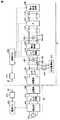
図1は、この発明の実施の形態1による電力伝送システムの全体構成図である。図1を参照して、電力伝送システムは、車両10と、送電装置20とを備える。送電装置20は、車両10の外部に設けられ、車両10に搭載される主蓄電装置300を充電することができる(以下、車両外部に設けられる送電装置20による車両10の主蓄電装置300の充電を「外部充電」とも称する。)。[Embodiment 1]
(Configuration of power transmission system)
1 is an overall configuration diagram of a power transmission system according to Embodiment 1 of the present invention. Referring to FIG. 1, the power transmission system includes a
車両10は、受電部100と、トランス120と、フィルタ回路150と、整流回路200と、主蓄電装置300と、動力生成装置400と、車両ECU(Electronic Control Unit)500と、通信装置510とを含む。また、車両10は、リレー210と、システムメインリレー(SMR)310と、交流電源部520と、リレー530と、センサ部540,550とをさらに含む。 The
なお、受電部100、トランス120、フィルタ回路150および整流回路200は、この発明における「モジュール」を形成し、このうち、トランス120、フィルタ回路150および整流回路200は、この発明における「機器ユニット」を形成する。 The
受電部100は、送電装置20の送電部700から出力される電力(交流)を非接触で受電するための共振器(コイルおよびキャパシタ)を含む。受電部100は、たとえば車体前方寄りの車体下部に設けられ、送電装置20が地表または地中に設けられる。 The
トランス120は、受電部100とフィルタ回路150との間に設けられ、受電部100をフィルタ回路150以降の機器と絶縁する。なお、トランス120は、車両10における必須の構成要素ではなく、必要に応じて設けられるものである。 The
フィルタ回路150は、トランス120と整流回路200との間に設けられ、受電部100による受電時に発生する高調波ノイズを抑制する。フィルタ回路150は、コイルおよびキャパシタを含むLCフィルタによって構成される。フィルタ回路150の具体的な構成については、後ほど説明する。 The
整流回路200は、受電部100によって受電された交流電力を整流して主蓄電装置300へ出力する。整流回路200は、整流器とともに平滑用のキャパシタを含んで構成される。整流回路200の具体的な構成についても、後ほど説明する。
主蓄電装置300は、再充電可能な直流電源であり、たとえばリチウムイオンやニッケル水素等の二次電池によって構成される。主蓄電装置300の電圧は、たとえば200V程度である。主蓄電装置300は、整流回路200から出力される電力を蓄えるほか、動力生成装置400によって発電される電力も蓄える。そして、主蓄電装置300は、その蓄えられた電力を動力生成装置400へ供給する。 Main
動力生成装置400は、主蓄電装置300に蓄えられる電力を用いて車両10の走行駆動力を発生する。特に図示しないが、動力生成装置400は、たとえば、主蓄電装置300から電力を受けるインバータ、インバータによって駆動されるモータ、モータによって駆動される駆動輪等を含む。なお、動力生成装置400は、主蓄電装置300を充電するための発電機と、その発電機を駆動可能なエンジンとを含んでもよい。
リレー210は、整流回路200と主蓄電装置300との間に設けられる。リレー210は、送電装置20による主蓄電装置300の外部充電時に車両ECU500によってオンされる。一方、外部充電に先立って行なわれる受電装置の異常検知処理の実行時には、リレー210はオフされる。SMR310は、主蓄電装置300と動力生成装置400との間に設けられる。SMR310は、動力生成装置400の起動が要求されると、車両ECU500によってオンされる。
センサ部540は、トランス120とフィルタ回路150との間に設けられる。センサ部540は、電圧センサ542と、電流センサ544とを含む。電圧センサ542は、トランス120とフィルタ回路150との間の電力線対間の電圧を検出し、その検出値を車両ECU500へ出力する。電流センサ544は、トランス120とフィルタ回路150との間の電力線対に流れる電流を検出し、その検出値を車両ECU500へ出力する。なお、センサ部540は、フィルタ回路150と整流回路200との間に設けてもよい。 The
センサ部550は、整流回路200とリレー210との間に設けられる。センサ部550は、電圧センサ552と、電流センサ554とを含む。電圧センサ552は、整流回路200の出力電圧を検出し、その検出値を車両ECU500へ出力する。電流センサ554は、整流回路200の出力電流を検出し、その検出値を車両ECU500へ出力する。
交流電源部520は、トランス120とフィルタ回路150との間の電力線対にリレー530を介して接続される。交流電源部520は、受電部100、トランス120、フィルタ回路150および整流回路200によって構成される受電装置の異常有無を検知するために、交流電流を発生して受電装置へ付与する。リレー210をオフにして受電装置を主蓄電装置300から電気的に切り離した状態で交流電源部520により受電装置に交流電流を付与したときのセンサ部540,550の検出値に基づいて、受電装置の異常有無を検知することができる。すなわち、この実施の形態1では、受電装置に交流電流を供給可能な交流電源部520が車両10に設けられ、送電装置20から車両10への電力伝送の開始前に車両単独で受電装置の異常有無を検知することができる。 AC
リレー530は、トランス120とフィルタ回路150との間の電力線対と、交流電源部520との間に設けられる。リレー530は、受電装置の異常有無を検知する処理の実行時に、車両ECU500によってオンされ、送電装置20による主蓄電装置300の外部充電時はオフされる。
車両ECU500は、CPU(Central Processing Unit)、記憶装置、入出力バッファ等を含み(いずれも図示せず)、各種センサからの信号の入力や各機器への制御信号の出力を行なうとともに、車両10における各機器の制御を行なう。一例として、車両ECU500は、車両10の走行制御や、主蓄電装置300の充電制御等を実行する。また、この発明に関する車両ECU500の主要な制御として、車両ECU500は、送電装置20から非接触で受電するための受電装置の異常有無を検知する異常検知処理を実行する。 The
なお、車両ECU500は、送電装置20による主蓄電装置300の充電が実行される際は、通信装置510を用いて送電装置20と通信を行ない、充電の開始/停止や車両10の受電状況等の情報を送電装置20とやり取りする。 When the main
一方、送電装置20は、電源部600と、フィルタ回路610と、送電部700と、電源ECU800と、通信装置810とを含む。電源部600は、商用系統電源等の外部電源900から電力を受け、所定の伝送周波数を有する交流電力を発生する。 On the other hand,
送電部700は、車両10の受電部100へ非接触で送電するための共振器(コイルおよびキャパシタ)を含む。送電部700は、伝送周波数を有する交流電力を電源部600から受け、送電部700の周囲に生成される電磁界を介して、車両10の受電部100へ非接触で送電する。送電部700の具体的な構成については、受電部100とともに後ほど説明する。
フィルタ回路610は、電源部600と送電部700との間に設けられ、電源部600から発生する高調波ノイズを抑制する。フィルタ回路610は、コイルおよびキャパシタを含むLCフィルタによって構成される。
電源ECU800は、CPU、記憶装置、入出力バッファ等を含み(いずれも図示せず)、各種センサからの信号の入力や各機器への制御信号の出力を行なうとともに、送電装置20における各機器の制御を行なう。一例として、電源ECU800は、伝送周波数を有する交流電力を電源部600が生成するように、電源部600のスイッチング制御を行なう。 The
なお、電源ECU800は、送電装置20による主蓄電装置300の充電が実行される際は、通信装置810を用いて車両10と通信を行ない、充電の開始/停止や車両10の受電状況等の情報を車両10とやり取りする。 When the main
この電力伝送システムにおいては、送電装置20において、電源部600からフィルタ回路610を介して送電部700へ、所定の伝送周波数を有する交流電力が供給される。送電部700および車両10の受電部100の各々は、共振器(コイルおよびキャパシタ)を含み、伝送周波数において互いに共振するように設計されている。送電部700および受電部100の共振強度を示すQ値は、100以上であることが好ましい。 In this power transmission system, AC power having a predetermined transmission frequency is supplied from the
電源部600から送電部700へ交流電力が供給されると、送電部700のコイルと受電部100のコイルとの間に形成される電磁界を通じて、送電部700から受電部100へエネルギー(電力)が移動する。そして、受電部100へ移動したエネルギー(電力)は、トランス120、フィルタ回路150および整流回路200を介して主蓄電装置300へ供給される。 When AC power is supplied from the
図2は、図1に示した受電部100および送電部700の回路構成の一例を示した図である。図2を参照して、受電部100は、コイル102と、キャパシタ104とを含む。キャパシタ104は、コイル102に直列に接続されてコイル102と共振回路を形成する。キャパシタ104は、受電部100の共振周波数を調整するために設けられる。キャパシタ104は、コイル102に並列に接続してもよい。あるいは、コイル102に直列に接続されるキャパシタ104とともに、コイル102に並列に接続されるキャパシタをさらに設ける構成としてもよい。なお、コイル102の浮遊容量を利用して所望の共振周波数が得られる場合には、キャパシタを設けない構成としてもよい。 FIG. 2 is a diagram illustrating an example of a circuit configuration of
送電部700は、コイル702と、キャパシタ704とを含む。キャパシタ704は、コイル702に直列に接続されてコイル702と共振回路を形成する。キャパシタ704は、送電部700の共振周波数を調整するために設けられる。キャパシタ704についても、キャパシタ704をコイル702に並列に接続してもよい。あるいは、コイル702に直列に接続されるキャパシタ704とともに、コイル702に並列に接続されるキャパシタをさらに設ける構成としてもよい。なお、コイル702の浮遊容量を利用して所望の共振周波数が得られる場合には、キャパシタを設けない構成としてもよい。
図3は、図1に示したフィルタ回路150の回路構成の一例を示した図である。図3を参照して、フィルタ回路150は、コイル152,156,160と、キャパシタ154,158とを含む。コイル152,156,160は、トランス120(図1)と整流回路200との間の電力線対の一方に設けられ、この実施の形態1では、コイル152,156,160は、端子T5,T7間において直列に接続される。キャパシタ154は、コイル152,156間において電力線対間に接続される。キャパシタ158は、コイル156,160間において電力線対間に接続される。 FIG. 3 is a diagram illustrating an example of a circuit configuration of the
なお、特に図示しないが、コイル152,156,160の各々を端子T6,T8間の電力線に分割して設けてもよい。また、フィルタ回路150を構成するコイルおよびキャパシタの配置および数は、図3に示したものに限定されるものではなく、フィルタ回路150に要求される能力によって適宜変更可能である。たとえば、フィルタ回路150は、コイル152,156およびキャパシタ154,158、またはコイル156,160およびキャパシタ154,158を含む4次のLCフィルタや、コイル152,156およびキャパシタ154を含む3次のLCフィルタ等によって構成してもよい。 Although not particularly illustrated, each of the
図4は、図1に示した整流回路200の回路構成の一例を示した図である。図4を参照して、整流回路200は、整流器と、整流器の出力側に設けられたキャパシタ202と、整流器とキャパシタ202との間に挿入されるチョークコイルとを含む。整流器は、たとえば4つのダイオードを含むダイオードブリッジ回路によって構成される。チョークコイルは設けなくてもよい。フィルタ回路150(図1)を通った交流電力が整流器により直流電力に整流され、キャパシタ202により平滑化されて主蓄電装置300(図1)へ出力される。 FIG. 4 is a diagram showing an example of the circuit configuration of the
図5は、図1に示した交流電源部520の構成例を示した図である。図5を参照して、交流電源部520は、補機用蓄電装置522と、インバータ524とによって構成され得る。補機用蓄電装置522は、車両10に搭載される各種補機や車両ECU500の電源となる直流電源であり、たとえば鉛やニッケル水素等の二次電池によって構成される。補機用蓄電装置522の電圧は、たとえば12Vや36Vである。FIG.5 is a diagram illustrating a configuration example of the AC
インバータ524は、補機用蓄電装置522から出力される直流電流を交流電流に変換して受電装置へ供給する。インバータ524は、たとえば単相ブリッジ回路によって構成される。 The
また、図6を参照して、交流電源部520は、主蓄電装置300(図1)と、インバータ524とによって構成してもよい。また、図7を参照して、交流電源部520は、ソーラー発電回路526と、インバータ524とによって構成してもよい。ソーラー発電回路526は、車両10のムーンルーフ(サンルーフ)に設けられるソーラーパネルによって発電し、直流電流を出力する。 Referring to FIG. 6, AC
なお、特に図示しないが、主蓄電装置300から出力される直流電力を商用交流電力(たとえばAC100V)に変換して車内コンセントに供給するインバータを車両10が搭載している場合には、そのインバータを交流電源部520に流用してもよい。 Although not particularly illustrated, when the
(受電装置の異常検知処理の説明)
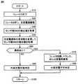
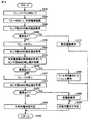
図8は、車両ECU500により実行される受電装置の異常有無検知についての第1の処理手順を説明するフローチャートである。このフローチャートに示される処理は、たとえば送電装置20から車両10への送電開始前に実行され、フィルタ回路150、トランス120または受電部100の異常有無がこの処理によって検知される。なお、整流回路200の異常有無は、図9に示される後述の処理によって検知される。この図8に示すフローチャートは、車両ECU500に予め格納されたプログラムを実行することによって実現される。あるいは、一部のステップについては、専用のハードウェア(電子回路)を構築して処理を実現することも可能である。(Description of abnormality detection processing of the power receiving device)
FIG. 8 is a flowchart illustrating a first processing procedure for detecting whether there is an abnormality in the power receiving device, which is executed by
図8とともに図1を参照して、車両ECU500は、リレー210をオフにする(ステップS10)。リレー210がオフにされて、受電部100、トランス120、フィルタ回路150および整流回路200を含む受電装置が主蓄電装置300から電気的に切り離されると、車両ECU500は、リレー530をオンにし、交流電源部520を駆動する(ステップS20)。これにより、交流電源部520から受電装置へ異常検知用の交流電流(周波数:f1)が供給される。 Referring to FIG. 1 together with FIG. 8,
交流電源部520から受電装置へ交流電流が供給されると、車両ECU500は、センサ部540の検出値を取得する(ステップS30)。ここでは、電圧センサ542および電流センサ544によりそれぞれ検出される交流電圧および交流電流の実効値が取得される。なお、取得された交流電圧および交流電流の実効値は、車両ECU500において一時的に記憶される。 When an AC current is supplied from AC
次いで、車両ECU500は、交流電源部520の周波数をf1からf2に変更してセンサ部540の検出値をさらに取得する(ステップS40)。ここでも、電圧センサ542および電流センサ544によりそれぞれ検出される交流電圧および交流電流の実効値が取得される。 Next,
そして、車両ECU500は、ステップS30,S40において取得されたセンサ部540の検出値に基づいて、受電装置のフィルタ回路150、トランス120または受電部100に異常が生じているか否かを判定する(ステップS60)。この異常有無の判定は、以下のようにして行なわれる。 Then,
すなわち、交流電源部520からは所定の交流電圧が与えられるところ、電流センサ544によって検出された交流電流の実効値が想定値(設計値)と異なる場合には、受電装置のフィルタ回路150、トランス120または受電部100に含まれるコイルおよびキャパシタの少なくとも1つに異常が生じているものと判断することができる。すなわち、コイルに異常が生じると、コイルのインダクタンスが変化し、そのコイルのインピーダンスが変化する。キャパシタに異常が生じたときも、キャパシタのキャパシタンスが変化し、そのキャパシタのインピーダンスが変化する。したがって、フィルタ回路150、トランス120または受電部100に含まれるコイルおよびキャパシタの少なくとも1つに異常が生じると、その異常が生じたコイルおよび/またはキャパシタのインピーダンスが変化し、その結果、電流センサ544によって検出される交流電流が想定値(設計値)から変化する。そこで、電流センサ544によって検出される交流電流に基づいて、フィルタ回路150、トランス120または受電部100に含まれるコイルおよびキャパシタの少なくとも1つに異常が生じているか否かを判断することができる。なお、コイルがコアを含む場合にコアに割れ等の異常が生じると、コイルのインダクタンスが変化し得る。また、キャパシタは、一般的に経年劣化によりキャパシタンスが低下する。 That is, when a predetermined alternating voltage is applied from the alternating current
このように、この実施の形態1によれば、受電装置のフィルタ回路150、トランス120または受電部100に含まれるいずれかのキャパシタの異常(キャパシタンスの変化)とともに、フィルタ回路150、トランス120または受電部100に含まれるいずれかのコイルの異常(インダクタンスの変化)も検知することができる。 As described above, according to the first embodiment, the
なお、ステップS40において交流電源部520の周波数を変更して電流センサ544の検出値をさらに取得したのは、異常検知の信頼性を高めるためである。すなわち、電流センサ544による検出値は、受電装置に含まれるコイルとキャパシタとの合成インピーダンスに基づく値であるので、コイルおよびキャパシタの双方に異常が生じているにも拘わらず、ある周波数では合成インピーダンスが正常値を示すことが起こり得る。そこで、交流電源部520から複数の周波数の交流電流を受電装置に与え、複数の周波数で電流センサ544の検出値に基づく異常検知を行なうことによって、異常検知の信頼性を高めることができる。 Note that the reason why the detection value of the
なお、ここでは、2つの異なる周波数でセンサ部540の検出値を取得するものとしたが、3つ以上の異なる周波数でセンサ部540の検出値を取得してもよい。一方、このような複数の周波数でセンサ部540の検出値を取得して異常検知を行なうことは、必須の事項ではない。すなわち、特に図示しないが、ステップS40に示される処理は、省略することも可能である。コイルおよびキャパシタの双方に異常が生じているにも拘わらず合成インピーダンスが正常値を示すような異常が生じるケースは稀であると想定される。 Here, the detection values of the
なお、整流回路200は、ダイオードブリッジ回路等の整流器を有するので、整流回路200の交流側に設けられるセンサ部540によって整流回路200の異常(具体的には整流器の出力側に設けられるキャパシタ202の異常)を検知することはできない。整流回路200の異常有無は、後述のように、整流回路200の出力側に設けられるセンサ部550の検出値に基づいて検知される。 Since the
ステップS60において、センサ部540の検出値に基づいて異常が生じているものと判定されると(ステップS60においてYES)、車両ECU500は、フィルタ回路150、トランス120または受電部100において異常が生じているものと判断する(ステップS70)。そして、車両ECU500は、送電装置20による主蓄電装置300の充電(外部充電)を実施不可であると判定する(ステップS80)。 If it is determined in step S60 that an abnormality has occurred based on the detection value of sensor unit 540 (YES in step S60),
一方、ステップS60において異常は生じていないものと判定されると(ステップS60においてNO)、車両ECU500は、送電装置20による主蓄電装置300の充電(外部充電)を実施可能であると判定する(ステップS90)。なお、ステップS90において外部充電を実施可能と判定されても、整流回路200の異常有無を検知する後述の処理(図9)において整流回路200に異常が生じているものと判断された場合には、外部充電は実施されない。 On the other hand, when it is determined in step S60 that no abnormality has occurred (NO in step S60),
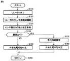
図9は、車両ECU500により実行される受電装置の異常有無検知についての第2の処理手順を説明するフローチャートである。このフローチャートに示される処理は、基本的には、図8のフローチャートに示される処理と同時並行的に実行される。このフローチャートに示される処理によって、整流回路200の異常有無が検知される。なお、この図9に示すフローチャートも、車両ECU500に予め格納されたプログラムを実行することによって実現される。あるいは、一部のステップについては、専用のハードウェア(電子回路)を構築して処理を実現することも可能である。 FIG. 9 is a flowchart illustrating a second processing procedure for detecting whether or not the power receiving device is abnormal, which is executed by
図9とともに図1を参照して、車両ECU500は、リレー210をオフにする(ステップS110)。さらに、車両ECU500は、リレー530をオンにし、交流電源部520を駆動する(ステップS120)。このステップS110,S210の処理は、それぞれ図8に示したステップS10,S20の処理と同じである。 Referring to FIG. 1 together with FIG. 9,
次いで、車両ECU500は、センサ部550の検出値を取得する(ステップS130)。具体的には、電圧センサ552により検出される直流電圧、および電流センサ554により検出される直流電流が取得される。 Next, the
そして、車両ECU500は、ステップS130において取得されたセンサ部550の検出値に基づいて、受電装置の整流回路200に異常が生じているか否かを判定する(ステップS160)。具体的には、電流センサ554により検出される直流電流の積算値が所定のしきい値に達するまでの到達時間が想定値(設計値)と異なるか否かによって、整流回路200に含まれるキャパシタ202のキャパシタンスが変化したものと判断することができる。 Then,
ステップS160において、センサ部550の検出値に基づいて異常が生じているものと判定されると(ステップS160においてYES)、車両ECU500は、整流回路200において異常が生じているものと判断する(ステップS170)。そして、車両ECU500は、送電装置20による主蓄電装置300の充電(外部充電)を実施不可であると判定する(ステップS180)。 If it is determined in step S160 that an abnormality has occurred based on the detection value of sensor unit 550 (YES in step S160),
一方、ステップS160において異常は生じていないものと判定されると(ステップS160においてNO)、車両ECU500は、送電装置20による主蓄電装置300の充電(外部充電)を実施可能であると判定する(ステップS190)。なお、ステップS190において外部充電を実施可能と判定されても、図8に示したステップS80において外部充電の実施は不可であると判定される場合には、外部充電は実施されない。 On the other hand, when it is determined in step S160 that no abnormality has occurred (NO in step S160),
なお、特に図示しないが、図8に示される処理と図9に示される処理とを1つのルーチンにおいて実行し、図8に示されるステップS10,S20,S80,S90の処理を、図9に示されるステップS110,S120,S180,S190の処理と共通化してもよい。 Although not particularly illustrated, the process shown in FIG. 8 and the process shown in FIG. 9 are executed in one routine, and the processes of steps S10, S20, S80, and S90 shown in FIG. 8 are shown in FIG. It may be made common with the processing of steps S110, S120, S180, and S190.
以上のように、この実施の形態1においては、リレー210よりも受電部100側に設けられる電力線に交流電源部520が電気的に接続され、送電装置20からの受電中でなくても車両単独で受電装置の異常有無を検知し得る。また、交流電源部520によって交流電流が供給されるので、コイルのインピーダンスの変化に基づきコイルの異常を検知し得る。したがって、この実施の形態1によれば、車両単独で受電装置の異常有無を検知することができ、かつ、キャパシタとともにコイルの異常も検知することができる。 As described above, in the first embodiment, AC
[実施の形態2]
この実施の形態2では、受電装置において受電部100の異常有無を区別して検知可能な構成が示される。[Embodiment 2]
In the second embodiment, a configuration is shown in which the power receiving device can detect whether or not the
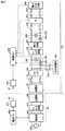
図10は、実施の形態2による電力伝送システムの全体構成図である。図10を参照して、車両10Aは、図1に示した車両10の構成において、リレー110をさらに含む。リレー110は、受電部100とトランス120との間に設けられる。リレー110は、送電装置20から車両10Aへの電力伝送時(外部充電時)に車両ECU500によってオンされる。一方、外部充電に先立って行なわれる受電装置の異常検知処理の実行時には、リレー110は、車両ECU500によってオン/オフが切替えられる。 FIG. 10 is an overall configuration diagram of a power transmission system according to the second embodiment. Referring to FIG. 10,
なお、車両10Aのその他の構成は、図1に示した車両10と同じである。また、この車両10Aにおいても、トランス120は、必須の構成要素ではなく、必要に応じて設けられるものである。 The other configuration of
図11は、実施の形態2において車両ECU500により実行される受電装置の異常有無検知についての第1の処理手順を説明するフローチャートである。このフローチャートは、実施の形態1における受電装置の異常有無検知についての、図8に示したフローチャートに対応するものである。整流回路200の異常有無は、図9に示した処理によって検知される。 FIG. 11 is a flowchart illustrating a first processing procedure for detecting whether there is an abnormality in the power receiving device, which is executed by
図11とともに図10を参照して、車両ECU500は、リレー210とともにリレー110をオフにする(ステップS12)。これにより、受電装置が主蓄電装置300から電気的に切り離されるとともに、受電部100がトランス120からさらに電気的に切り離される。その後、ステップS20へ処理が移行され、車両ECU500は、リレー530をオンにし、交流電源部520を駆動する。なお、ステップS20〜S60は、図8において説明したので、その説明を繰り返さない。 Referring to FIG. 10 together with FIG. 11,
ステップS60において、センサ部540の検出値に基づいて異常が生じているものと判定されると(ステップS60においてYES)、車両ECU500は、フィルタ回路150またはトランス120において異常が生じているものと判断する(ステップS72)。リレー110はオフされているので、ここでは受電部100の異常有無は検知されない。ステップS72の処理後、ステップS80へ処理が移行され、外部充電は実施不可であると判定される。 If it is determined in step S60 that an abnormality has occurred based on the detection value of sensor unit 540 (YES in step S60),
一方、ステップS60において異常は生じていないものと判定されると(ステップS60においてNO)、車両ECU500は、リレー110をオンにする(ステップS62)。これにより、受電部100がトランス120に電気的に接続され、交流電源部520から受電部100へ異常検知用の交流電流が供給される。そして、車両ECU500は、センサ部540の検出値を再度取得し(ステップS64)、その取得したセンサ部540の検出値に基づいて、受電装置の受電部100に異常が生じているか否かを判定する(ステップS66)。 On the other hand, when it is determined in step S60 that no abnormality has occurred (NO in step S60),
ステップS66において、センサ部540の検出値に基づいて異常が生じているものと判定されると(ステップS66においてYES)、車両ECU500は、受電部100において異常が生じているものと判断する(ステップS74)。その後、ステップS80へ処理が移行され、外部充電は実施不可であると判定される。一方、ステップS66において異常は生じていないものと判定されると(ステップS66においてNO)、ステップS90へ処理が移行され、外部充電は実施可能であると判定される。 If it is determined in step S66 that an abnormality has occurred based on the detection value of sensor unit 540 (YES in step S66),
なお、特に図示しないが、ステップS64,S66における受電部100の異常検知処理においても、交流電源部520の周波数を変更してセンサ部540の検出値を取得し、複数の周波数でセンサ部540の検出値に基づく異常検知を行なうことによって、異常検知の信頼性を高めてもよい。 Although not particularly illustrated, also in the abnormality detection process of the
以上のように、この実施の形態2においては、リレー110によりトランス120以降の機器ユニットから受電部100が電気的に切り離されて、機器ユニットの異常有無が検知される。したがって、この実施の形態2によれば、受電部100と区別してトランス120以降の機器ユニットの異常有無を検知することができる。また、この実施の形態2によれば、トランス120以降の機器ユニットと区別して受電部100の異常有無をさらに検知することができる。 As described above, in the second embodiment, the
[変形例]
図12は、実施の形態2の変形例による電力伝送システムの全体構成図である。図12を参照して、車両10Bは、交流電源部520がフィルタ回路150と整流回路200との間の電力線対に電気的に接続される点において車両10Aと異なる。車両10Bのその他の構成は、車両10Aと同じである。なお、センサ部540も、フィルタ回路150と整流回路200との間の電力線対に設けてもよい。[Modification]
FIG. 12 is an overall configuration diagram of a power transmission system according to a modification of the second embodiment. Referring to FIG. 12,
また、特に図示しないが、図1に示した実施の形態1の構成に対しても、交流電源部520がフィルタ回路150と整流回路200との間の電力線対にリレー530を介して電気的に接続されるようにしてもよい。 Although not particularly shown, the AC
[実施の形態3]
上記の実施の形態1,2および変形例では、交流電源部520は、整流回路200の入力側(交流側)に電気的に接続されるものとしたが、この実施の形態3では、交流電源部520は、整流回路200の出力側(直流側)に電気的に接続される。[Embodiment 3]
In the first and second embodiments and the modifications described above, the AC
図13は、実施の形態3による電力伝送システムの全体構成図である。図13を参照して、車両10Cは、交流電源部520が整流回路200とリレー210との間の電力線対に電気的に接続される点において車両10Aと異なる。そして、車両10Cは、整流回路200をバイパスするためのバイパス回路と、リレー560とをさらに含む。車両10Cのその他の構成は、車両10Aと同じである。 FIG. 13 is an overall configuration diagram of a power transmission system according to the third embodiment. Referring to FIG. 13,
リレー560は、整流回路200の出力側(直流側)と入力側(交流側)とをバイパスする電力線に設けられ、車両ECU500によってオン/オフが切替えられる。リレー560をオフにした状態で交流電源部520から交流電流を供給することによって、整流回路200の異常有無(具体的には整流器の出力側に設けられるキャパシタ202の異常有無)を検知することができる。
また、リレー560をオンにすることによって、整流回路200の入力側(交流側)に設けられるフィルタ回路150、トランス120または受電部100の異常有無を検知することができる。さらに、リレー110のオン/オフを切替えることによって、受電部100と、トランス120またはフィルタ回路150との異常検知を切り分けることができる。 Further, by turning on
図14は、実施の形態3において車両ECU500により実行される受電装置の異常有無検知についての処理手順を説明するフローチャートである。このフローチャートに示される処理も、たとえば送電装置20から車両10Cへの送電開始前に実行される。この図14に示すフローチャートも、車両ECU500に予め格納されたプログラムを実行することによって実現される。あるいは、一部のステップについては、専用のハードウェア(電子回路)を構築して処理を実現することも可能である。 FIG. 14 is a flowchart illustrating a processing procedure for detecting whether there is an abnormality in the power receiving device, which is executed by
図14とともに図13を参照して、車両ECU500は、リレー110,210,560をオフにする(ステップS310)。すなわち、整流回路200のバイパス回路は遮断され、受電部100はトランス120から電気的に切り離される。そして、車両ECU500は、リレー530をオンにし、交流電源部520を駆動する(ステップS320)。これにより、交流電源部520から受電装置へ異常検知用の交流電流が供給される。 Referring to FIG. 13 together with FIG. 14,
次いで、車両ECU500は、センサ部550の検出値を取得する(ステップS330)。具体的には、電圧センサ552により検出される直流電圧、および電流センサ554により検出される直流電流が取得される。 Next, the
そして、車両ECU500は、ステップS330において取得されたセンサ部550の検出値に基づいて、受電装置の整流回路200に異常が生じているか否かを判定する(ステップS360)。このステップS360において実行される処理は、図9に示したステップS160において実行される処理と同じであり、具体的には、整流回路200に含まれるキャパシタ202の異常(キャパシタンスの変化)の有無が検知される。 Then,
ステップS360において、センサ部550の検出値に基づいて異常が生じているものと判定されると(ステップS360においてYES)、車両ECU500は、整流回路200において異常が生じているものと判断する(ステップS370)。そして、車両ECU500は、送電装置20による主蓄電装置300の充電(外部充電)を実施不可であると判定する(ステップS380)。 If it is determined in step S360 that an abnormality has occurred based on the detection value of sensor unit 550 (YES in step S360),
一方、ステップS360において異常は生じていないものと判定されると(ステップS360においてNO)、車両ECU500は、リレー560をオンにする(ステップS390)。これにより、整流回路200がバイパスされ、交流電源部520からフィルタ回路150およびトランス120へ交流電流が供給される。 On the other hand, when it is determined in step S360 that no abnormality has occurred (NO in step S360),
ステップS400以降において実行される処理は、図11に示した実施の形態2におけるステップS30以降において実行される処理と同じであるので、説明を繰り返さない。 Since the processing executed after step S400 is the same as the processing executed after step S30 in the second embodiment shown in FIG. 11, description thereof will not be repeated.
なお、上記においては、実施の形態2における車両10Aの構成において、交流電源部520が整流回路200の出力側(直流側)に接続されるものとしたが、実施の形態1における車両10の構成において、交流電源部520が整流回路200の出力側(直流側)に接続されるものであってもよい。すなわち、この実施の形態3は、リレー110が設けられない構成にも適用可能である。 In the above, in the configuration of
以上のように、この実施の形態3によっても、実施の形態1や実施の形態2と同様の効果を得ることができる。 As described above, this third embodiment can provide the same effects as those of the first and second embodiments.
なお、上記において、受電部100、トランス120、フィルタ回路150および整流回路200は、この発明における「モジュール」の一実施例を形成し、このうち、トランス120、フィルタ回路150および整流回路200は、この発明における「機器ユニット」の一実施例を形成する。また、リレー210は、この発明における「第1リレー」の一実施例に対応し、リレー110は、この発明における「第2リレー」の一実施例に対応する。さらに、電流センサ544は、この発明における「第1電流センサ」の一実施例に対応し、電流センサ554は、この発明における「第2電流センサ」の一実施例に対応する。また、さらに、車両ECU500は、この発明における「制御装置」の一実施例に対応し、リレー560は、この発明における「第3リレー」の一実施例に対応する。 In the above description, the
今回開示された各実施の形態は、適宜組合わせて実施することも予定されている。そして、今回開示された実施の形態は、すべての点で例示であって制限的なものではないと考えられるべきである。本発明の範囲は、上記した実施の形態の説明ではなくて特許請求の範囲によって示され、特許請求の範囲と均等の意味および範囲内でのすべての変更が含まれることが意図される。 The embodiments disclosed this time are also scheduled to be implemented in appropriate combinations. The embodiment disclosed this time should be considered as illustrative in all points and not restrictive. The scope of the present invention is shown not by the above description of the embodiments but by the scope of claims for patent, and is intended to include meanings equivalent to the scope of claims for patent and all modifications within the scope.
10,10A〜10C 車両、20 送電装置、100 受電部、102,152,156,160,702 コイル、104,154,158,202,704 キャパシタ、110,210,530,560 リレー、120 トランス、150,610 フィルタ回路、200 整流回路、300 主蓄電装置、310 SMR、400 動力生成装置、500 車両ECU、510,810 通信装置、520 交流電源部、522 補機用蓄電装置、524 インバータ、526 ソーラー発電回路、540,550 センサ部、542,552 電圧センサ、544,554 電流センサ、600 電源部、700 送電部、800 電源ECU。 10, 10A-10C vehicle, 20 power transmission device, 100 power receiving unit, 102, 152, 156, 160, 702 coil, 104, 154, 158, 202, 704 capacitor, 110, 210, 530, 560 relay, 120 transformer, 150 , 610 Filter circuit, 200 Rectifier circuit, 300 Main power storage device, 310 SMR, 400 Power generation device, 500 Vehicle ECU, 510,810 Communication device, 520 AC power supply unit, 522 Auxiliary power storage device, 524 Inverter, 526 Solar power generation Circuit, 540, 550 Sensor unit, 542, 552 Voltage sensor, 544, 554 Current sensor, 600 power supply unit, 700 Power transmission unit, 800 Power supply ECU.
Claims (8)
Translated fromJapanese前記機器ユニットと前記蓄電装置との間に設けられる第1リレーと、
前記第1リレーよりも前記受電部側に設けられる電力線に交流電流を供給可能に構成された交流電源部と、
前記電力線の電流を検出する電流センサとを備え、
前記モジュールは、コイルとキャパシタとを含み、さらに、
前記第1リレーが電力遮断状態である場合に前記交流電源部から前記電力線に交流電流が供給されているとき、前記電流センサの検出値に基づいて前記コイルおよび前記キャパシタの少なくとも一方に異常が生じているか否かを検知する制御装置と、
前記受電部と前記機器ユニットとの間に設けられる第2リレーとを備え、
前記コイルは、前記機器ユニットに設けられる第1コイルを含み、
前記キャパシタは、前記機器ユニットに設けられる第1キャパシタを含み、
前記交流電源部は、前記第1リレーと前記第2リレーとの間に電気的に接続され、
前記電流センサは、前記第1リレーと前記第2リレーとの間に設けられる電力線の電流を検出し、
前記制御装置は、前記第1リレーおよび前記第2リレーが電力遮断状態である場合に前記交流電源部から交流電流が供給されているとき、前記電流センサの検出値に基づいて前記第1コイルおよび前記第1キャパシタの少なくとも一方に異常が生じているか否かを検知する、受電装置。A module including a power reception unit for receiving power output from the power transmission device in a contactless manner, and a device unit provided between the power reception unit and a power storage device that stores the power received by the power reception unit;
A first relay provided between the device unit and the power storage device;
An AC power supply unit configured to be able to supply an AC current to a power line provided on the power receiving unit side of the first relay;
A current sensor for detecting the current of the power line,
The module includes a coil and a capacitor, and
When an alternating current is supplied from the alternating current power supply unit to the power line when the first relay is in a power cut-off state, an abnormality occurs in at least one of the coil and the capacitor based on a detection value of the current sensor. A control device for detecting whether or not
Anda second relay provided between said power receiving portion and the device unit,
The coil includes a first coil provided in the device unit,
The capacitor includes a first capacitor provided in the device unit,
The AC power supply unit is electrically connected between the first relay and the second relay,
The current sensor detects a current of a power line provided between the first relay and the second relay,
When the first relay and the second relay are in a power cut-off state, the control device is configured to supply the first coil and the first coil based on a detection value of the current sensor when an AC current is supplied from the AC power supply unit. detecting whether or not an abnormality in at least one of said first capacitor hasoccurred, powered device.
前記キャパシタは、前記受電部に設けられる第2キャパシタをさらに含み、
前記制御装置は、前記第1コイルおよび前記第1キャパシタに異常が生じていないことを検知した後、前記第2リレーを通電状態にして、前記電流センサの検出値に基づいて前記第2コイルおよび前記第2キャパシタの少なくとも一方に異常が生じているか否かを検知する、請求項1に記載の受電装置。The coil further includes a second coil provided in the power receiving unit,
The capacitor further includes a second capacitor provided in the power receiving unit,
The controller, after detecting that no abnormality has occurred in the first coil and the first capacitor, energizes the second relay, and based on the detection value of the current sensor, The power receiving device according toclaim 1 , wherein whether or not an abnormality has occurred in at least one of the second capacitors is detected.
前記受電部により受電された電力を整流する整流回路と、
前記受電部と前記整流回路との間に設けられるフィルタ回路とを含み、
前記第1コイルおよび前記第1キャパシタは、前記フィルタ回路に含まれ、
前記キャパシタは、前記整流回路に設けられる第3キャパシタをさらに含み、
前記電流センサは、
前記第2リレーと前記整流回路との間に設けられる電力線の電流を検出する第1電流センサと、
前記整流回路と前記第1リレーとの間の電力線の電流を検出する第2電流センサとを含み、
前記交流電源部は、前記第2リレーと前記フィルタ回路との間の電力線に電気的に接続され、
前記制御装置は、
前記第1電流センサの検出値に基づいて前記フィルタ回路または前記受電部の異常有無を検知し、
前記第2電流センサの検出値に基づいて前記整流回路の異常有無を検知する、請求項1または2に記載の受電装置。The equipment unit is
A rectifier circuit for rectifying the power received by the power receiving unit;
Including a filter circuit provided between the power reception unit and the rectifier circuit,
The first coil and the first capacitor are included in the filter circuit;
The capacitor further includes a third capacitor provided in the rectifier circuit,
The current sensor is
A first current sensor for detecting a current of a power line provided between the second relay and the rectifier circuit;
A second current sensor for detecting a current of a power line between the rectifier circuit and the first relay;
The AC power supply unit is electrically connected to a power line between the second relay and the filter circuit,
The controller is
Detecting the presence or absence of an abnormality in the filter circuit or the power receiving unit based on a detection value of the first current sensor;
The power receiving device according toclaim 1 , wherein presence or absence of abnormality of the rectifier circuit is detected based on a detection value of the second current sensor.
前記受電部により受電された電力を整流する整流回路と、
前記受電部と前記整流回路との間に設けられるフィルタ回路とを含み、
前記第1コイルおよび前記第1キャパシタは、前記フィルタ回路に含まれ、
前記キャパシタは、前記整流回路に設けられる第3キャパシタをさらに含み、
前記電流センサは、
前記第2リレーと前記整流回路との間に設けられる電力線の電流を検出する第1電流センサと、
前記整流回路と前記第1リレーとの間の電力線の電流を検出する第2電流センサとを含み、
前記交流電源部は、前記フィルタ回路と前記整流回路との間の電力線に電気的に接続され、
前記制御装置は、
前記第1電流センサの検出値に基づいて前記フィルタ回路または前記受電部の異常有無を検知し、
前記第2電流センサの検出値に基づいて前記整流回路の異常有無を検知する、請求項1または2に記載の受電装置。The equipment unit is
A rectifier circuit for rectifying the power received by the power receiving unit;
Including a filter circuit provided between the power reception unit and the rectifier circuit,
The first coil and the first capacitor are included in the filter circuit;
The capacitor further includes a third capacitor provided in the rectifier circuit,
The current sensor is
A first current sensor for detecting a current of a power line provided between the second relay and the rectifier circuit;
A second current sensor for detecting a current of a power line between the rectifier circuit and the first relay;
The AC power supply unit is electrically connected to a power line between the filter circuit and the rectifier circuit,
The controller is
Detecting the presence or absence of an abnormality in the filter circuit or the power receiving unit based on the detection value of the first current sensor
The power receiving device according toclaim 1 , wherein presence or absence of abnormality of the rectifier circuit is detected based on a detection value of the second current sensor.
前記受電部により受電された電力を整流する整流回路と、
前記受電部と前記整流回路との間に設けられるフィルタ回路とを含み、
前記第1コイルおよび前記第1キャパシタは、前記フィルタ回路に含まれ、
前記キャパシタは、前記整流回路の整流器の出力側に設けられる第3キャパシタをさらに含み、
前記電流センサは、
前記第2リレーと前記整流回路との間に設けられる電力線の電流を検出する第1電流センサと、
前記整流回路と前記第1リレーとの間の電力線の電流を検出する第2電流センサとを含み、
前記交流電源部は、前記整流回路と前記第1リレーとの間の電力線に電気的に接続され、
前記受電装置は、
前記整流回路をバイパスするためのバイパス回路と、
前記バイパス回路に設けられる第3リレーとをさらに備え、
前記制御装置は、
前記第3リレーを電力遮断状態にして、前記第2電流センサの検出値に基づいて前記第3キャパシタの異常有無を検知し、
前記第3リレーを通電状態にして、前記第1電流センサの検出値に基づいて前記フィルタ回路または前記受電部の異常有無を検知する、請求項1または2に記載の受電装置。The equipment unit is
A rectifier circuit for rectifying the power received by the power receiving unit;
Including a filter circuit provided between the power reception unit and the rectifier circuit,
The first coil and the first capacitor are included in the filter circuit;
The capacitor further includes a third capacitor provided on the output side of the rectifier of the rectifier circuit,
The current sensor is
A first current sensor for detecting a current of a power line provided between the second relay and the rectifier circuit;
A second current sensor for detecting a current of a power line between the rectifier circuit and the first relay;
The AC power supply unit is electrically connected to a power line between the rectifier circuit and the first relay,
The power receiving device is:
A bypass circuit for bypassing the rectifier circuit;
A third relay provided in the bypass circuit;
The controller is
The third relay is in a power cut-off state, and the presence or absence of an abnormality of the third capacitor is detected based on the detection value of the second current sensor,
3. The power receiving device according toclaim 1 , wherein the third relay is energized to detect whether the filter circuit or the power receiving unit is abnormal based on a detection value of the first current sensor.
前記機器ユニットと前記蓄電装置との間に設けられる第1リレーと、
前記第1リレーよりも前記受電部側に設けられる電力線に交流電流を供給可能に構成された交流電源部と、
前記電力線の電流を検出する電流センサとを備え、
前記モジュールは、コイルとキャパシタとを含み、さらに、
前記第1リレーが電力遮断状態である場合に前記交流電源部から前記電力線に交流電流が供給されているとき、前記電流センサの検出値に基づいて前記コイルおよび前記キャパシタの少なくとも一方に異常が生じているか否かを検知する制御装置を備え、
前記交流電源部は、前記交流電流の周波数を変更可能に構成され、
前記制御装置は、複数の周波数の交流電流についての前記電流センサの検出値に基づいて、前記コイルおよび前記キャパシタに異常が生じているか否かを検知する、受電装置。A module including a power reception unit for receiving power output from the power transmission device in a contactless manner, and a device unit provided between the power reception unit and a power storage device that stores the power received by the power reception unit;
A first relay provided between the device unit and the power storage device;
An AC power supply unit configured to be able to supply an AC current to a power line provided on the power receiving unit side of the first relay;
A current sensor for detecting the current of the power line,
The module includes a coil and a capacitor, and
When an alternating current is supplied from the alternating current power supply unit to the power line when the first relay is in a power cut-off state, an abnormality occurs in at least one of the coil and the capacitor based on a detection value of the current sensor. Equipped with a control device to detect whether or not
The AC power supply unit is configured to be able to change the frequency of the AC current,
Wherein the control device, based on a detection value of said current sensor for alternating current of a plurality of frequencies, to detect whether or not abnormality in the coil and the capacitoroccurs, powered device.
前記受電部により受電された電力を整流する整流回路と、
前記受電部と前記整流回路との間に設けられるフィルタ回路と、
前記受電部と前記フィルタ回路との間に設けられる絶縁トランスとを含む、請求項1または2に記載の受電装置。The equipment unit is
A rectifier circuit for rectifying the power received by the power receiving unit;
A filter circuit provided between the power reception unit and the rectifier circuit;
The power receiving device according toclaim 1 , further comprising an insulating transformer provided between the power receiving unit and the filter circuit.
前記機器ユニットと前記蓄電装置との間に設けられる第1リレーと、
前記第1リレーよりも前記受電部側に設けられる電力線に交流電流を供給可能に構成された交流電源部と、
前記電力線の電流を検出する電流センサとを備え、
前記モジュールは、コイルとキャパシタとを含み、さらに、
前記第1リレーが電力遮断状態である場合に前記交流電源部から前記電力線に交流電流が供給されているとき、前記電流センサの検出値に基づいて前記コイルおよび前記キャパシタの少なくとも一方に異常が生じているか否かを検知する制御装置を備え、
前記機器ユニットは、
前記受電部により受電された電力を整流する整流回路と、
前記受電部と前記整流回路との間に設けられるフィルタ回路と、
前記受電部と前記フィルタ回路との間に設けられる絶縁トランスとを含む、受電装置。A module including a power reception unit for receiving power output from the power transmission device in a contactless manner, and a device unit provided between the power reception unit and a power storage device that stores the power received by the power reception unit;
A first relay provided between the device unit and the power storage device;
An AC power supply unit configured to be able to supply an AC current to a power line provided on the power receiving unit side of the first relay;
A current sensor for detecting the current of the power line,
The module includes a coil and a capacitor, and
When an alternating current is supplied from the alternating current power supply unit to the power line when the first relay is in a power cut-off state, an abnormality occurs in at least one of the coil and the capacitor based on a detection value of the current sensor. Equipped with a control device to detect whether or not
The equipment unit is
A rectifier circuit for rectifying the power received by the power receiving unit;
A filter circuit provided between the power reception unit and the rectifier circuit;
And an insulating transformer provided between the filter circuit and the power receivingunit, powered device.
Priority Applications (5)
| Application Number | Priority Date | Filing Date | Title |
|---|---|---|---|
| JP2014030568AJP6160504B2 (en) | 2014-02-20 | 2014-02-20 | Power receiving device |
| PCT/IB2015/000178WO2015173614A1 (en) | 2014-02-20 | 2015-02-17 | Power receiving device |
| EP15716862.6AEP3107753B1 (en) | 2014-02-20 | 2015-02-17 | Power receiving device |
| CN201580008561.9ACN106030971B (en) | 2014-02-20 | 2015-02-17 | Power receiving system |
| US15/118,270US10141786B2 (en) | 2014-02-20 | 2015-02-17 | Power receiving device |
Applications Claiming Priority (1)
| Application Number | Priority Date | Filing Date | Title |
|---|---|---|---|
| JP2014030568AJP6160504B2 (en) | 2014-02-20 | 2014-02-20 | Power receiving device |
Publications (3)
| Publication Number | Publication Date |
|---|---|
| JP2015156742A JP2015156742A (en) | 2015-08-27 |
| JP2015156742A5 JP2015156742A5 (en) | 2016-07-28 |
| JP6160504B2true JP6160504B2 (en) | 2017-07-12 |
Family
ID=52875724
Family Applications (1)
| Application Number | Title | Priority Date | Filing Date |
|---|---|---|---|
| JP2014030568AActiveJP6160504B2 (en) | 2014-02-20 | 2014-02-20 | Power receiving device |
Country Status (5)
| Country | Link |
|---|---|
| US (1) | US10141786B2 (en) |
| EP (1) | EP3107753B1 (en) |
| JP (1) | JP6160504B2 (en) |
| CN (1) | CN106030971B (en) |
| WO (1) | WO2015173614A1 (en) |
Families Citing this family (5)
| Publication number | Priority date | Publication date | Assignee | Title |
|---|---|---|---|---|
| EP3325477B1 (en) | 2015-07-21 | 2019-05-01 | H. Hoffnabb-La Roche Ag | Novel tricyclic 4-pyridone-3-carboxylic acid derivatives for the treatment and prophylaxis of hepatitis b virus infection |
| JPWO2017115625A1 (en)* | 2015-12-28 | 2018-10-18 | 日本電産株式会社 | Mobile system |
| MY173094A (en)* | 2016-05-18 | 2019-12-25 | Nissan Motor | Coil position detection method for non-contact power supply system, and power reception device |
| JP7069836B2 (en)* | 2018-03-02 | 2022-05-18 | トヨタ自動車株式会社 | Coil unit |
| US11777334B2 (en)* | 2021-11-11 | 2023-10-03 | Beta Air, Llc | System for charging multiple power sources and monitoring diode currents for faults |
Family Cites Families (28)
| Publication number | Priority date | Publication date | Assignee | Title |
|---|---|---|---|---|
| JP3234909B2 (en)* | 1996-12-13 | 2001-12-04 | シャープ株式会社 | Inverter control device and inverter control method |
| JP2000171506A (en)* | 1998-12-04 | 2000-06-23 | Hitachi Kiden Kogyo Ltd | Inspection method for resonant capacitors in automatic guided vehicles |
| DE10133865A1 (en)* | 2001-07-12 | 2003-01-30 | Philips Corp Intellectual Pty | Electrical circuitry |
| US8169185B2 (en)* | 2006-01-31 | 2012-05-01 | Mojo Mobility, Inc. | System and method for inductive charging of portable devices |
| JP4864985B2 (en)* | 2007-02-16 | 2012-02-01 | 株式会社小松製作所 | Generator driving device, hybrid vehicle, and generator driving device control method |
| JP4453741B2 (en)* | 2007-10-25 | 2010-04-21 | トヨタ自動車株式会社 | Electric vehicle and vehicle power supply device |
| JP2010016985A (en)* | 2008-07-03 | 2010-01-21 | Sanyo Electric Co Ltd | Method of data transmission in electric power transmission, and charging stand and battery built-in device using the method |
| US8421409B2 (en)* | 2008-09-19 | 2013-04-16 | Toyota Jidosha Kabushiki Kaisha | Noncontact power receiving apparatus for electrically-powered vehicle and vehicle including the same |
| WO2010131348A1 (en)* | 2009-05-14 | 2010-11-18 | トヨタ自動車株式会社 | Vehicle charging unit |
| GB2490074B (en)* | 2010-02-08 | 2014-02-19 | Access Business Group Int Llc | Input parasitic metal detection |
| JP5290228B2 (en)* | 2010-03-30 | 2013-09-18 | 株式会社日本自動車部品総合研究所 | Voltage detector, abnormality detection device, contactless power transmission device, contactless power receiving device, contactless power feeding system, and vehicle |
| JP5126324B2 (en)* | 2010-09-10 | 2013-01-23 | トヨタ自動車株式会社 | Power supply apparatus and control method of power supply system |
| US9219378B2 (en)* | 2010-11-01 | 2015-12-22 | Qualcomm Incorporated | Wireless charging of devices |
| US9278625B2 (en)* | 2010-12-16 | 2016-03-08 | Denso Corporation | Power supply apparatus for vehicles that selects between conductive and non-conductive power transfer |
| US9266441B2 (en)* | 2011-01-19 | 2016-02-23 | Technova Inc. | Contactless power transfer system |
| JP5703988B2 (en)* | 2011-06-17 | 2015-04-22 | トヨタ自動車株式会社 | Power receiving device, power transmitting device, vehicle, and non-contact power feeding system |
| US20140191720A1 (en)* | 2011-09-21 | 2014-07-10 | Toyota Jidosha Kabushiki Kaisha | Charging system and charging control method of electric powered vehicle |
| JP5378488B2 (en)* | 2011-11-18 | 2013-12-25 | 富士重工業株式会社 | Charging system and electric vehicle |
| JP5772535B2 (en) | 2011-11-18 | 2015-09-02 | トヨタ自動車株式会社 | Power transmission system and vehicle |
| JP2013126326A (en)* | 2011-12-15 | 2013-06-24 | Toyota Motor Corp | Non-contact power reception device and vehicle mounting the same, non-contact power transmission device, and non-contact power supply system |
| JP5668676B2 (en) | 2011-12-15 | 2015-02-12 | トヨタ自動車株式会社 | Power receiving device, vehicle including the same, power transmitting device, and power transmission system |
| JP5664544B2 (en) | 2011-12-27 | 2015-02-04 | トヨタ自動車株式会社 | Non-contact power receiving device and non-contact charging system |
| JP5825108B2 (en) | 2012-01-16 | 2015-12-02 | トヨタ自動車株式会社 | Power receiving device and power transmitting device |
| JP5718830B2 (en) | 2012-01-16 | 2015-05-13 | トヨタ自動車株式会社 | vehicle |
| JP5810944B2 (en) | 2012-01-31 | 2015-11-11 | トヨタ自動車株式会社 | Vehicle and power transmission system |
| JP5696674B2 (en) | 2012-02-17 | 2015-04-08 | トヨタ自動車株式会社 | Electric vehicle |
| JP2014176170A (en)* | 2013-03-07 | 2014-09-22 | Toshiba Corp | Power incoming apparatus and charging system |
| JP2015080296A (en)* | 2013-10-15 | 2015-04-23 | 株式会社豊田自動織機 | Power reception apparatus and non-contact power transmission device |
- 2014
- 2014-02-20JPJP2014030568Apatent/JP6160504B2/enactiveActive
- 2015
- 2015-02-17EPEP15716862.6Apatent/EP3107753B1/ennot_activeNot-in-force
- 2015-02-17WOPCT/IB2015/000178patent/WO2015173614A1/enactiveApplication Filing
- 2015-02-17CNCN201580008561.9Apatent/CN106030971B/ennot_activeExpired - Fee Related
- 2015-02-17USUS15/118,270patent/US10141786B2/enactiveActive
Also Published As
| Publication number | Publication date |
|---|---|
| JP2015156742A (en) | 2015-08-27 |
| US20160359368A1 (en) | 2016-12-08 |
| US10141786B2 (en) | 2018-11-27 |
| CN106030971B (en) | 2018-06-19 |
| EP3107753A1 (en) | 2016-12-28 |
| EP3107753B1 (en) | 2017-05-10 |
| CN106030971A (en) | 2016-10-12 |
| WO2015173614A8 (en) | 2016-01-14 |
| WO2015173614A1 (en) | 2015-11-19 |
Similar Documents
| Publication | Publication Date | Title |
|---|---|---|
| CN106487078B (en) | Non-contact power transmission system and power transmission device | |
| JP4478729B1 (en) | Resonant non-contact charging device | |
| JP5126324B2 (en) | Power supply apparatus and control method of power supply system | |
| JP5703988B2 (en) | Power receiving device, power transmitting device, vehicle, and non-contact power feeding system | |
| JP5648694B2 (en) | Non-contact power supply system and power supply equipment | |
| JP5937631B2 (en) | Contactless power transmission system and charging station | |
| JP5287863B2 (en) | Non-contact power receiving apparatus and vehicle equipped with the same | |
| JP5979125B2 (en) | Contactless power transmission equipment | |
| JP6160504B2 (en) | Power receiving device | |
| JP2010154625A (en) | Resonant non-contact charging device | |
| JP2015156743A (en) | Power receiving device | |
| JP2012257395A (en) | Non-contact power receiving apparatus and vehicle including the same, non-contact power transmission apparatus, and non-contact power transmission system | |
| CN105531899A (en) | Contactless Power Transmission Device | |
| JP6056778B2 (en) | Non-contact power transmission system | |
| JPWO2016162996A1 (en) | Contactless power supply system | |
| JP5884698B2 (en) | Non-contact power receiving device | |
| JP2015144529A (en) | Non-contact power transmission system and charge station | |
| JP5962687B2 (en) | Contactless power transmission system and charging station | |
| JP2015154603A (en) | Non-contact power transmission system | |
| JP2017093089A (en) | Power transmission device, power reception device and power transmission system | |
| JP2016059197A (en) | Noncontact power reception device | |
| KR20160121911A (en) | Charging device included in electronic vehicle |
Legal Events
| Date | Code | Title | Description |
|---|---|---|---|
| A521 | Request for written amendment filed | Free format text:JAPANESE INTERMEDIATE CODE: A523 Effective date:20160613 | |
| A621 | Written request for application examination | Free format text:JAPANESE INTERMEDIATE CODE: A621 Effective date:20160613 | |
| A977 | Report on retrieval | Free format text:JAPANESE INTERMEDIATE CODE: A971007 Effective date:20170228 | |
| A131 | Notification of reasons for refusal | Free format text:JAPANESE INTERMEDIATE CODE: A131 Effective date:20170307 | |
| A521 | Request for written amendment filed | Free format text:JAPANESE INTERMEDIATE CODE: A523 Effective date:20170427 | |
| TRDD | Decision of grant or rejection written | ||
| A01 | Written decision to grant a patent or to grant a registration (utility model) | Free format text:JAPANESE INTERMEDIATE CODE: A01 Effective date:20170516 | |
| A61 | First payment of annual fees (during grant procedure) | Free format text:JAPANESE INTERMEDIATE CODE: A61 Effective date:20170529 | |
| R151 | Written notification of patent or utility model registration | Ref document number:6160504 Country of ref document:JP Free format text:JAPANESE INTERMEDIATE CODE: R151 |