JP6159990B2 - Disaster-resistant network design assistance system, main server and non-main server - Google Patents
Disaster-resistant network design assistance system, main server and non-main serverDownload PDFInfo
- Publication number
- JP6159990B2 JP6159990B2JP2013202577AJP2013202577AJP6159990B2JP 6159990 B2JP6159990 B2JP 6159990B2JP 2013202577 AJP2013202577 AJP 2013202577AJP 2013202577 AJP2013202577 AJP 2013202577AJP 6159990 B2JP6159990 B2JP 6159990B2
- Authority
- JP
- Japan
- Prior art keywords
- main server
- network
- delay
- distance
- main
- Prior art date
- Legal status (The legal status is an assumption and is not a legal conclusion. Google has not performed a legal analysis and makes no representation as to the accuracy of the status listed.)
- Active
Links
Images


Landscapes
- Data Exchanges In Wide-Area Networks (AREA)
Description
Translated fromJapanese本発明は、1つのメインサーバおよび2つの非メインサーバを用いて、ネットワークに接続されているネットワーク機器間の距離を予測し、耐災害性(BCP:Business Contingency Plan)ネットワーク設計考案の援助を行なう技術に関する。 The present invention predicts the distance between network devices connected to the network using one main server and two non-main servers, and assists in designing a BCP (Business Contingency Plan) network. Regarding technology.
例えば、特許文献1には、バス型のフィールドネットワークにおいて、ネットワークに接続されるスレーブ、リピータ等の位置関係を検出する技術が開示されている。この技術は、主にバス型のネットワークにおいて有用であり、ネットワークの端点におかれた測定器から、位置関係を把握したいノードまでの遅延を測定し、その関係性を調べることで、ネットワークに接続されている機器の相対位置関係を把握できる。小〜中規模なネットワーク機器の位置関係を把握するには有用である。 For example,
しかしながら、特許文献1記載の技術を用いることによって、機器の相対的な位置関係を把握することはできるが、支線が多く存在する大規模なネットワークにおいては、その支線の数分だけ測定機器を設ける必要があることが難点である。また、機器間の距離を予測する機構が記載されていないため、例えば、日本全国に配置された機器から離れた機器を見つけ出し、耐災害性ネットワークの設計考案の支援に使用するには適していない。 However, by using the technique described in
本発明は、このような事情に鑑みてなされたものであり、全国に配置された機器間の相対的位置関係と計算距離を求めることができる耐災害性ネットワーク設計援助システム、メインサーバおよび非メインサーバを提供することを目的とする。 The present invention has been made in view of such circumstances, and a disaster-tolerant network design assistance system, a main server, and a non-main device capable of obtaining a relative positional relationship and a calculation distance between devices arranged nationwide. The purpose is to provide a server.
(1)上記の目的を達成するために、本発明は、以下のような手段を講じた。すなわち、本発明の耐災害性ネットワーク設計援助システムは、1つのメインサーバおよび2つの非メインサーバを用いて、ネットワークに接続されているネットワーク機器間の距離を予測する耐災害性ネットワーク設計援助システムであって、前記メインサーバは、ユーザからデータの入力を受け付ける一方、データを出力するユーザインタフェースと、複数のネットワーク機器のIP(Internet Protocol)アドレスおよび設置場所を示す情報を管理する位置情報管理部と、前記2つの非メインサーバおよび前記各ネットワーク機器に対してパルス信号を送信し、遅延を測定する第1の遅延計測部と、前記測定された遅延および前記各非メインサーバで測定された遅延に基づいて、前記各ネットワーク機器の位置座標を算出すると共に、前記各位置座標を用いて前記各ネットワーク機器間の距離を算出する計算処理部と、前記非メインサーバに前記各ネットワーク機器のIPアドレス情報を送信する一方、前記非メインサーバから前記各ネットワーク機器との間で測定された遅延を示す情報を取得するメインサーバ通信部と、を備え、前記非メインサーバは、前記メインサーバおよび前記各ネットワーク機器に対してパルス信号を送信し、遅延を測定する第2の遅延計測部と、前記メインサーバから前記各ネットワーク機器のIPアドレス情報を受信する一方、前記メインサーバに前記各ネットワーク機器との間で測定した遅延を示す情報を送信する非メインサーバ通信部と、を備え、前記ユーザインタフェースで前記算出した前記各ネットワーク機器間の距離を出力することを特徴とする。 (1) In order to achieve the above object, the present invention takes the following measures. That is, the disaster tolerant network design assistance system of the present invention is a disaster tolerant network design assistance system that predicts the distance between network devices connected to the network using one main server and two non-main servers. The main server receives input of data from a user, and outputs data, and a location information management unit that manages information indicating IP (Internet Protocol) addresses and installation locations of a plurality of network devices, A first delay measurement unit that transmits a pulse signal to the two non-main servers and each network device and measures a delay; and the measured delay and the delay measured by each non-main server And calculating the position coordinates of each of the network devices, A calculation processing unit that calculates a distance between the network devices using a position coordinate, and transmits the IP address information of the network devices to the non-main server, while the non-main server and the network devices A main server communication unit that acquires information indicating the delay measured in step (b), wherein the non-main server transmits a pulse signal to the main server and each network device, and measures a delay. A non-main server communication unit that receives information indicating a delay measured between the network device and the main server while receiving the IP address information of the network device from the main server, and a delay measurement unit; And outputting the calculated distance between the network devices using the user interface. To do.
このように、測定された各遅延に基づいて、各ネットワーク機器の位置座標を算出すると共に、各位置座標を用いて各ネットワーク機器間の距離を算出するので、ネットワーク機器間の相対位置関係と計算距離を求めることができ、どの組合せのネットワーク機器が遠い位置にあるかを瞬時に計算できる。これにより、耐災害性ネットワーク設計における設計者の工数を削減することが可能となる。 In this way, the position coordinates of each network device are calculated based on each measured delay, and the distance between each network device is calculated using each position coordinate. The distance can be obtained, and it can be instantaneously calculated which combination of network devices are at a distant position. Thereby, it becomes possible to reduce the man-hours of the designer in the disaster-resistant network design.
(2)また、本発明の耐災害性ネットワーク設計援助システムにおいて、前記計算処理部は、前記メインサーバと前記2つの非メインサーバとの距離および遅延量並びに前記2つの非メインサーバ間の距離および遅延量に基づいて、単位時間当たりの距離を示す基準値を算出し、前記基準値と前記測定された各遅延とに基づいて、前記各ネットワーク機器の位置座標を算出することを特徴とする。 (2) Further, in the disaster tolerant network design assistance system of the present invention, the calculation processing unit includes a distance and a delay amount between the main server and the two non-main servers, a distance between the two non-main servers, and A reference value indicating a distance per unit time is calculated based on the delay amount, and a position coordinate of each network device is calculated based on the reference value and each measured delay.
このように、メインサーバと2つの非メインサーバとの距離および遅延量並びに2つの非メインサーバ間の距離および遅延量に基づいて、単位時間当たりの距離を示す基準値を算出し、基準値と各遅延とに基づいて、各ネットワーク機器の位置座標を算出するので、各ネットワーク機器が離れているかどうかを迅速に把握することが可能となる。各ネットワーク機器の絶対的な位置を求める必要が無いことから、簡易かつ迅速に各ネットワーク機器の相対的な位置関係を提示し、設計の用に供することが可能となる。 Thus, based on the distance and delay amount between the main server and the two non-main servers and the distance and delay amount between the two non-main servers, the reference value indicating the distance per unit time is calculated, and the reference value and Since the position coordinates of each network device are calculated based on each delay, it is possible to quickly grasp whether or not each network device is separated. Since there is no need to obtain the absolute position of each network device, it is possible to present the relative positional relationship of each network device simply and quickly and use it for design.
(3)また、本発明の耐災害性ネットワーク設計援助システムは、前記ユーザインタフェースにおいて、算出した前記ネットワーク機器間の距離を、大きい順に表示することを特徴とする。 (3) The disaster-resistant network design assistance system according to the present invention is characterized in that the calculated distance between the network devices is displayed in descending order on the user interface.
このように、算出した前記ネットワーク機器間の距離を、大きい順に表示するので、簡易かつ迅速に各ネットワーク機器の相対的な位置関係を提示することが可能となる。 Thus, since the calculated distance between the network devices is displayed in descending order, the relative positional relationship between the network devices can be presented easily and quickly.
(4)また、本発明のメインサーバは、1つのメインサーバおよび2つの非メインサーバを用いて、ネットワークに接続されているネットワーク機器間の距離を予測する耐災害性ネットワーク設計援助システムに適用されるメインサーバであって、ユーザからデータの入力を受け付ける一方、データを出力するユーザインタフェースと、複数のネットワーク機器のIPアドレスおよび設置場所を示す情報を管理する位置情報管理部と、前記2つの非メインサーバおよび前記各ネットワーク機器に対してパルス信号を送信し、遅延を測定する第1の遅延計測部と、前記測定された遅延および前記各非メインサーバで測定された遅延に基づいて、前記各ネットワーク機器の位置座標を算出すると共に、前記各位置座標を用いて前記各ネットワーク機器間の距離を算出する計算処理部と、前記非メインサーバに前記各ネットワーク機器のIPアドレス情報を送信する一方、前記非メインサーバから前記各ネットワーク機器との間で測定された遅延を示す情報を取得するメインサーバ通信部と、を備え、前記ユーザインタフェースで前記算出した前記各ネットワーク機器間の距離を出力することを特徴とする。 (4) The main server of the present invention is applied to a disaster-resistant network design assistance system that predicts the distance between network devices connected to the network using one main server and two non-main servers. A main server that accepts data input from a user and outputs data, a location information management unit that manages information indicating IP addresses and installation locations of a plurality of network devices, A first delay measurement unit that transmits a pulse signal to the main server and each network device and measures delay, and based on the measured delay and the delay measured by each non-main server, While calculating the position coordinates of the network device, each network using the position coordinates Information indicating the delay measured between the non-main server and each network device while transmitting the IP address information of each network device to the non-main server And a main server communication unit for acquiring the information, and outputting the calculated distance between the network devices by the user interface.
このように、測定された各遅延に基づいて、各ネットワーク機器の位置座標を算出すると共に、各位置座標を用いて各ネットワーク機器間の距離を算出するので、ネットワーク機器間の相対位置関係と計算距離を求めることができ、どの組合せのネットワーク機器が遠い位置にあるかを瞬時に計算できる。これにより、耐災害性ネットワーク設計における設計者の工数を削減することが可能となる。 In this way, the position coordinates of each network device are calculated based on each measured delay, and the distance between each network device is calculated using each position coordinate. The distance can be obtained, and it can be instantaneously calculated which combination of network devices are at a distant position. Thereby, it becomes possible to reduce the man-hours of the designer in the disaster-resistant network design.
(5)また、本発明の非メインサーバは、1つのメインサーバおよび2つの非メインサーバを用いて、ネットワークに接続されているネットワーク機器間の距離を予測する耐災害性ネットワーク設計援助システムに適用される非メインサーバであって、上記(4)記載のメインサーバおよび前記各ネットワーク機器に対してパルス信号を送信し、遅延を測定する第2の遅延計測部と、上記(4)記載のメインサーバから前記各ネットワーク機器のIPアドレス情報を受信する一方、上記(4)記載のメインサーバに前記各ネットワーク機器との間で測定した遅延を示す情報を送信する非メインサーバ通信部と、を備えることを特徴とする。 (5) Further, the non-main server of the present invention is applied to a disaster-resistant network design assistance system that predicts the distance between network devices connected to the network using one main server and two non-main servers. A non-main server configured to transmit a pulse signal to the main server described in (4) and each network device and measure a delay; and a main described in (4) A non-main server communication unit that receives IP address information of each network device from a server and transmits information indicating a delay measured with each network device to the main server described in (4) above. It is characterized by that.
このように、測定された各遅延に基づいて、メインサーバで各ネットワーク機器の位置座標を算出すると共に、各位置座標を用いて各ネットワーク機器間の距離を算出するので、ネットワーク機器間の相対位置関係と計算距離を求めることができ、どの組合せのネットワーク機器が遠い位置にあるかを瞬時に計算できる。これにより、耐災害性ネットワーク設計における設計者の工数を削減することが可能となる。 Thus, based on each measured delay, the main server calculates the position coordinates of each network device and calculates the distance between each network device using each position coordinate. Relationships and calculation distances can be obtained, and which combination of network devices are located far away can be calculated instantaneously. Thereby, it becomes possible to reduce the man-hours of the designer in the disaster-resistant network design.
本発明によれば、ネットワーク機器間の相対位置関係と計算距離を求めることができ、どの組合せのネットワーク機器が遠い位置にあるかを瞬時に計算できる。これにより、耐災害性ネットワーク設計における設計者の工数を削減することが可能となる。 According to the present invention, it is possible to obtain a relative positional relationship and a calculation distance between network devices, and it is possible to instantaneously calculate which combination of network devices is at a far position. Thereby, it becomes possible to reduce the man-hours of the designer in the disaster-resistant network design.
耐災害性ネットワークの設計を行なう場合、設計対象機器の絶対的な位置が把握できることが望ましい。しかし、冗長をはかることを目的とし、仮想マシンを複数作成する場合は、その仮想マシンを構築するネットワーク機器の絶対的な位置が分からなくても、構築しようとしているネットワーク機器同士が離れているかどうかさえ分かれば、設計を行なうことができる。つまり、絶対的な位置がわからなくとも、相対的な位置関係がわかれば設計することができる。 When designing a disaster tolerant network, it is desirable to be able to grasp the absolute position of the design target device. However, when creating multiple virtual machines for the purpose of redundancy, whether or not the network devices to be built are separated even if the absolute location of the network device that builds the virtual machine is not known If you know, you can design. That is, even if the absolute position is not known, it can be designed if the relative positional relationship is known.
本実施形態では、設計対象機器の相対的な位置関係を知る手法として遅延を用いる。例えば、あるネットワーク機器に対して通信を行なう場合、一般的にはそのネットワーク機器への道のりが長いほど遅延が大きくなり、遅延によりそのネットワーク機器までのおおよその距離を把握することが可能である。本実施形態では、遅延を用いて設計対象の位置関係を把握するが、特許文献1で課題となっていたように、端点に測定装置を置く手法は、本実施形態では採用せず、分散的に配置された3台の測定装置、すなわち、1つのメインサーバと2つの非メインサーバを用いて位置推定を行ない、推定されたネットワーク機器を座標平面上の点として表現する。これにより、ネットワーク機器間の距離を予測する。これにより、離れた場所にあるネットワーク機器の組合せを算出し、耐災害性ネットワークの設計援助を行なう。 In the present embodiment, delay is used as a method for knowing the relative positional relationship of the design target devices. For example, when communicating with a network device, in general, the longer the path to the network device, the larger the delay, and the approximate distance to the network device can be grasped by the delay. In this embodiment, the positional relationship of the design object is grasped by using a delay. However, as has been a problem in
このように、本実施形態は、設計対象機器の位置はわからないが、IP(Internet Protocol)アドレスはわかるという場合に有用である。 As described above, the present embodiment is useful when the position of the design target device is not known but the IP (Internet Protocol) address is known.
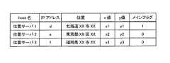
図1は、データベースの構成を示す図である。本実施形態は、耐災害性ネットワークの設計を行なう際に、設計者が、自身が設計対象とする機器とそのIPアドレスの情報は保持しているが、位置情報を保持していない場合を前提としている。例えば、設計者は、図1に示す情報を保持しているとする。例えば、設計者は保持しているネットワーク機器上に新たに仮想マシンを構築する上で、耐災害性を考慮し、なるべく離れた機器の組合せを見つけたいとする。 FIG. 1 is a diagram showing the structure of a database. This embodiment is based on the assumption that when designing a disaster-tolerant network, the designer retains information on the device to be designed and its IP address, but does not retain location information. It is said. For example, it is assumed that the designer holds the information shown in FIG. For example, a designer wants to find a combination of devices as far apart as possible in consideration of disaster tolerance when constructing a new virtual machine on a network device held by the designer.
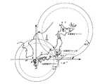
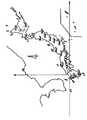
図2は、地図上に座標平面を定めた様子を示す図である。設計者はネットワーク機器の相対位置を把握するため、次に述べる前処理を行なう。図2に示すように、ある地点を原点とする座標平面を考える。 FIG. 2 is a diagram illustrating a state in which a coordinate plane is defined on a map. The designer performs the following pre-processing to grasp the relative position of the network device. As shown in FIG. 2, a coordinate plane having a certain point as an origin is considered.
図3は、位置推定サーバを3台設置した様子を示す図である。座標平面上におけるそれらの座標等を位置情報管理データベースに保存する。例えば、図1に示すように、位置推定サーバ1の座標は、(x1,y1)であり、位置推定サーバ2の座標は(x2,y2)であり、位置推定サーバ3の座標は(x3,y3)である。また、位置推定サーバの中の1台(例えば、位置推定サーバ1)は、全ての計算処理を統括するメインサーバとしてデータベース内にフラグを立てておく。メインサーバ以外を非メインサーバとして区別する。 FIG. 3 is a diagram illustrating a state in which three position estimation servers are installed. Those coordinates on the coordinate plane are stored in the position information management database. For example, as shown in FIG. 1, the coordinates of the
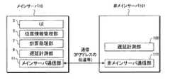
図4は、位置情報管理データベースの例を示す図である。また、図5は、位置推定サーバのメインサーバと非メインサーバの概略構成を示すブロック図である。メインサーバ10では、ユーザがUI(User Interface)3を通じてメインサーバ10にアクセスする。メインサーバ10は、位置情報管理部5に位置情報管理データベースを保持している。計算処理部7は、ネットワーク機器の位置推定のための計算を行なう。遅延計測部9は、位置を推定したい機器への遅延を計測する。メインサーバ通信部11は、非メインサーバ101宛てに位置を推定したいネットワーク機器のIPアドレスの伝達する機能等を具備している。 FIG. 4 is a diagram illustrating an example of the location information management database. FIG. 5 is a block diagram showing a schematic configuration of the main server and the non-main server of the position estimation server. In the
非メインサーバ101は、遅延計測部109と、非メインサーバ通信部111とを備える。遅延計測部109は、メインサーバ10から伝達されたIPアドレスを用いて、各ネットワーク機器との間の遅延を測定する。非メインサーバ通信部111は、メインサーバ通信部11と通信を行なう。 The non-main server 101 includes a
図6は、各位置推定サーバ間の距離と遅延量を示す図である。位置推定サーバを設置した後、設置した位置から各位置推定サーバ間の距離を求め、また位置推定サーバ間で、パルス信号(例えばping)を送信し、各位置推定サーバ間の遅延量を算出する。図6では、例えば、位置推定サーバ1と2との距離が「k12」、遅延量が「c12」であり、位置推定サーバ1と3との距離が「k13」、遅延量が「c13」であり、位置推定サーバ2と3との距離が「k23」、遅延量が「c23」である。このようにして求めた距離と遅延量より、単位時間当たりの距離を算出し、それを位置推定の「基準値」として、メインサーバとなる位置推定サーバに登録しておく。ここまでの処理が、前処理となる。 FIG. 6 is a diagram illustrating the distance between each position estimation server and the delay amount. After installing the position estimation server, the distance between the position estimation servers is obtained from the installed position, and a pulse signal (for example, ping) is transmitted between the position estimation servers to calculate the delay amount between the position estimation servers. . In FIG. 6, for example, the distance between the
上記の位置推定「基準値」の求め方は、例えば、下記のように、3つの位置推定サーバ間の平均単位時間距離を求めればよい。 The position estimation “reference value” can be obtained by, for example, obtaining an average unit time distance between three position estimation servers as described below.

図7Aは、メインサーバである位置推定サーバで求めた位置推定対象機器の存在範囲を示す図である。前処理が完了した後、実際に位置推定処理を行なう。ユーザはメインサーバである位置推定サーバにログインし、位置を推定したい設計対象機器の全てのIPアドレス情報を、UIを通じて入力する。メインサーバである位置推定サーバは、その情報を位置推定管理データベースに格納し、座標が求まっていないネットワーク機器1台に対して、そのIPアドレス宛にpingを打つなどし、遅延量を求める。図7Aに示すように、半径が「遅延×位置推定基準値」の大きさの円を描き、自身の座標を中心とする円の数式を求める。 FIG. 7A is a diagram illustrating an existence range of position estimation target devices obtained by a position estimation server that is a main server. After the preprocessing is completed, position estimation processing is actually performed. The user logs in to the position estimation server, which is the main server, and inputs all the IP address information of the design target device whose position is to be estimated through the UI. The position estimation server, which is the main server, stores the information in the position estimation management database, and obtains a delay amount by, for example, pinging the IP address of one network device whose coordinates are not obtained. As shown in FIG. 7A, a circle whose radius is “delay × position estimation reference value” is drawn, and a mathematical formula of a circle centered on its own coordinates is obtained.
図7Bは、メインサーバである位置推定サーバから非メインサーバである位置推定サーバに設計対象となるネットワーク機器のIPアドレスを伝達する様子を示す図である。図7Cは、非メインサーバである位置推定サーバからメインサーバである位置推定サーバにRTT値の結果を伝達する様子を示す図である。図7Bに示すように、メインサーバである位置推定サーバは、非メインサーバ宛てに、位置推定対象であるIPアドレス情報を伝達する。また、図7Bに示すように、非メインサーバはメインサーバと同様にpingを打つなどし、そのRTT(Round Trip Time)の値をメインサーバへ返す。 FIG. 7B is a diagram illustrating a state in which an IP address of a network device to be designed is transmitted from a position estimation server that is a main server to a position estimation server that is a non-main server. FIG. 7C is a diagram illustrating a state in which the result of the RTT value is transmitted from the position estimation server that is the non-main server to the position estimation server that is the main server. As illustrated in FIG. 7B, the position estimation server that is the main server transmits the IP address information that is the position estimation target to the non-main server. Further, as shown in FIG. 7B, the non-main server pings the same as the main server, and returns its RTT (Round Trip Time) value to the main server.
図8A〜図8Cは、3台の位置推定サーバで求めた位置推定対象機器の存在範囲を示すである。図9は、位置推定処理を繰り返した機器の位置推定結果を示す図である。メインサーバは、図8A〜図8Cに示すように、メインサーバ内の計算処理部にて、各非メインサーバにおける位置推定対象機器の存在範囲を示す円を求める。次に、3つの円が重なる部分の重心座標を求め、そこを機器の位置座標として位置推定管理データベースに登録する。これを繰り返し、図9に示すように、全ての位置を推定したい設計対象機器の位置座標登録を行なっていく。 8A to 8C show the existence ranges of the position estimation target devices obtained by the three position estimation servers. FIG. 9 is a diagram illustrating a position estimation result of a device in which the position estimation process is repeated. As shown in FIGS. 8A to 8C, the main server obtains a circle indicating the existence range of the position estimation target devices in each non-main server by the calculation processing unit in the main server. Next, the center-of-gravity coordinates of the portion where the three circles overlap are obtained and registered as position coordinates of the device in the position estimation management database. This is repeated, and as shown in FIG. 9, registration of the position coordinates of the design target device for which all positions are to be estimated is performed.
このように位置を推定したい設計対象機器全ての位置座標を求めたら、位置座標により、機器間の計算距離を求め、遠距離にある組合せを上位n位までを設計者にUIを通じて提示し、設計者はそれに基づいて仮想マシンをどの機器上に構築していくかを設計する。 Once the position coordinates of all the design target devices whose positions are to be estimated are obtained in this way, the calculated distance between the devices is obtained from the position coordinates, and the combinations up to the top n ranks are presented to the designer through the UI. The person designs on which device the virtual machine will be built based on that.
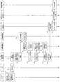
図10A〜図10Cは、本実施形態に係る位置推定処理の概要を示すシーケンスチャートである。図面の記載の都合上、3枚にわたっているが、紙面の上から下へ向かう方向が時間の流れの方向である。ユーザが、設計対象ノード全てのホスト名とIPアドレスの情報を、UI3を通じて入力する(ステップS1)。UI3は、この情報を受信し(ステップS2)、位置情報管理部5は、データベースへの情報の格納を行なう(ステップS3)。次に、位置情報管理部5は、データベースにおいて、座標が空欄の対象ノードのIPアドレスを1つ伝達する(ステップS4)。そして、遅延計測部9は、pingを実施して(ステップS5)、RTT値を伝達する(ステップS6)。 10A to 10C are sequence charts showing an overview of the position estimation process according to the present embodiment. For convenience of drawing, there are three sheets, but the direction from the top to the bottom of the page is the direction of time flow. The user inputs information on the host names and IP addresses of all the design target nodes through the UI 3 (step S1). The
次に、計算処理部7は、距離(円の半径)を算出し(ステップS7)、メインサーバの座標をリクエストする(ステップS8)。位置情報管理部5がこのリクエストを受信すると(ステップS9)、メインサーバの座標を計算処理部7に伝達する(ステップS10)。計算処理部7は、対象ノードの存在推定のための円の数式を算出し、一時保存し(ステップS11)、一時保存の完了を位置情報管理部5に伝達する(ステップS12)。位置情報管理部5は、一時保存完了の伝達を受けると(ステップS13)、IPアドレスの伝達をメインサーバ通信部11に指示する(ステップS14)。 Next, the
メインサーバ通信部11は、IPアドレス伝達指示を受領すると(ステップS15)、非メインサーバへのIPアドレスの伝達を行なう(ステップS16)。非メインサーバ通信部111は、IPアドレス情報を受信すると(ステップS17)、遅延計測部109にそのIPアドレスを伝達し、遅延計測部109は、pingを実施する(ステップS18)。遅延計測部109は、RTT値を測定し、非メインサーバ通信部111にRTT値の伝達指示を行なう(ステップS19)。非メインサーバ通信部111は、RTT値の伝達指示を受けると、メインサーバ通信部11に対して、RTT値の伝達を行なう(ステップS20)。 When receiving the IP address transmission instruction (step S15), the main
メインサーバ通信部11がRTT値を受信すると(ステップS21)、計算処理部7に対して、RTT値を伝達する(ステップS22)。計算処理部7は、RTT値を用いて、距離(円の半径)を算出する(ステップS23)。次に、計算処理部7は、位置情報管理部5に対して、非メインサーバの座標をリクエストする(ステップS24)。位置情報管理部5は、計算処理部7からリクエストを受信すると(ステップS25)、非メインサーバの座標を計算処理部7に伝達する(ステップS26)。計算処理部7は、非メインサーバの座標を受信すると、対象ノードの存在推定のための円の数式を算出し、一時保持する(ステップS27)。 When the main
計算処理部7は、3つの円の重なった部分の重心座標を算出する(ステップS28)。そして、重心座標を位置情報管理部5に伝達する(ステップS29)。位置情報管理部5は、重心座標を受領すると(ステップS30)、データベースへの格納を行なう(ステップS31)。そして、データベース中の座標が空欄であるノードが存在するかどうかを判断し(ステップS32)、存在する場合は、ステップS4に遷移し、存在しない場合は、ステップS33に遷移する。 The
位置情報管理部5は、対象ノードの座標を計算処理部7に伝達し(ステップS33)、計算処理部7は、対象ノードの座標を受領すると(ステップS34)、対象ノードの距離を計算する(ステップS35)。そして、遠距離ノードの組み合わせをUI3に伝達する(ステップS36)。UI3は、図11に示すように、遠距離ノードの組み合わせを、例えば、上位n番まで、画像としてユーザに提示し(ステップS37)、終了する。 The position
以上説明したように、本実施形態によれば、全国に配置された機器の位置を推定し、それを平面座標上の点として捉える事で、機器間の相対位置関係と計算距離を求めることができ、どの組合せの機器が遠い位置にあるかを瞬時に計算できるので、耐災害性ネットワーク設計などにおける設計者の工数を削減できる。 As described above, according to the present embodiment, it is possible to estimate the position of devices arranged in the whole country and to obtain the relative positional relationship and calculation distance between devices by capturing them as points on the plane coordinates. In addition, since it is possible to instantaneously calculate which combination of devices is located at a distant position, it is possible to reduce the man-hours of the designer in designing a disaster-resistant network.
1〜3 位置推定サーバ
5 位置情報管理部
7 計算処理部
9 遅延計測部
10 メインサーバ
11 メインサーバ通信部
101 非メインサーバ
109 遅延計測部
111 非メインサーバ通信部
1-3
Claims (5)
Translated fromJapanese前記メインサーバは、
ユーザからデータの入力を受け付ける一方、データを出力するユーザインタフェースと、
複数のネットワーク機器のIPアドレスおよび設置場所を示す情報を管理する位置情報管理部と、
前記2つの非メインサーバおよび前記各ネットワーク機器に対してパルス信号を送信し、遅延を測定する第1の遅延計測部と、
前記測定された遅延および前記各非メインサーバで測定された遅延に基づいて、前記各ネットワーク機器の位置座標を算出すると共に、前記各位置座標を用いて前記各ネットワーク機器間の距離を算出する計算処理部と、
前記非メインサーバに前記各ネットワーク機器のIPアドレス情報を送信する一方、前記非メインサーバから前記各ネットワーク機器との間で測定された遅延を示す情報を取得するメインサーバ通信部と、を備え、
前記非メインサーバは、
前記メインサーバおよび前記各ネットワーク機器に対してパルス信号を送信し、遅延を測定する第2の遅延計測部と、
前記メインサーバから前記各ネットワーク機器のIPアドレス情報を受信する一方、前記メインサーバに前記各ネットワーク機器との間で測定した遅延を示す情報を送信する非メインサーバ通信部と、を備え、
前記ユーザインタフェースで前記算出した前記各ネットワーク機器間の距離を出力することを特徴とする耐災害性ネットワーク設計援助システム。A disaster tolerant network design assistance system that predicts the distance between network devices connected to a network using one main server and two non-main servers,
The main server is
A user interface that accepts data input from the user while outputting data;
A location information management unit that manages information indicating IP addresses and installation locations of a plurality of network devices;
A first delay measuring unit that transmits a pulse signal to the two non-main servers and each network device and measures a delay;
Based on the measured delay and the delay measured at each non-main server, the position coordinates of the network devices are calculated, and the distance between the network devices is calculated using the position coordinates. A processing unit;
A main server communication unit that transmits the IP address information of each network device to the non-main server, and acquires information indicating a delay measured between the non-main server and each network device;
The non-main server is
A second delay measuring unit that transmits a pulse signal to the main server and each network device and measures a delay;
A non-main server communication unit that receives IP address information of each network device from the main server, and transmits information indicating a delay measured with the network device to the main server,
The disaster-tolerant network design assistance system, wherein the calculated distance between the network devices is output by the user interface.
ユーザからデータの入力を受け付ける一方、データを出力するユーザインタフェースと、
複数のネットワーク機器のIPアドレスおよび設置場所を示す情報を管理する位置情報管理部と、
前記2つの非メインサーバおよび前記各ネットワーク機器に対してパルス信号を送信し、遅延を測定する第1の遅延計測部と、
前記測定された遅延および前記各非メインサーバで測定された遅延に基づいて、前記各ネットワーク機器の位置座標を算出すると共に、前記各位置座標を用いて前記各ネットワーク機器間の距離を算出する計算処理部と、
前記非メインサーバに前記各ネットワーク機器のIPアドレス情報を送信する一方、前記非メインサーバから前記各ネットワーク機器との間で測定された遅延を示す情報を取得するメインサーバ通信部と、を備え、
前記ユーザインタフェースで前記算出した前記各ネットワーク機器間の距離を出力することを特徴とするメインサーバ。A main server applied to a disaster tolerant network design assistance system that predicts a distance between network devices connected to a network using one main server and two non-main servers,
A user interface that accepts data input from the user while outputting data;
A location information management unit that manages information indicating IP addresses and installation locations of a plurality of network devices;
A first delay measuring unit that transmits a pulse signal to the two non-main servers and each network device and measures a delay;
Based on the measured delay and the delay measured at each non-main server, the position coordinates of the network devices are calculated, and the distance between the network devices is calculated using the position coordinates. A processing unit;
A main server communication unit that transmits the IP address information of each network device to the non-main server, and acquires information indicating a delay measured between the non-main server and each network device;
A main server that outputs the calculated distance between the network devices by the user interface.
前記メインサーバおよび前記各ネットワーク機器に対してパルス信号を送信し、遅延を測定する第2の遅延計測部と、
前記メインサーバから前記各ネットワーク機器のIPアドレス情報を受信する一方、前記メインサーバに前記各ネットワーク機器との間で測定した遅延を示す情報を送信する非メインサーバ通信部と、を備えることを特徴とする非メインサーバ装置。A non-main server applied to a disaster-tolerant network design assistance system that predicts a distance between network devices connected to a network using one main server and two non-main servers according toclaim 4. ,
A second delay measuring unit that transmits a pulse signal to the main server and each network device and measures a delay;
The one that receives the IP address information of each network device from the main server, comprising: a, a non-main server communication unit which transmits information indicating the delay measurement betweenthe main server to each network device A non-main server device.
Priority Applications (1)
| Application Number | Priority Date | Filing Date | Title |
|---|---|---|---|
| JP2013202577AJP6159990B2 (en) | 2013-09-27 | 2013-09-27 | Disaster-resistant network design assistance system, main server and non-main server |
Applications Claiming Priority (1)
| Application Number | Priority Date | Filing Date | Title |
|---|---|---|---|
| JP2013202577AJP6159990B2 (en) | 2013-09-27 | 2013-09-27 | Disaster-resistant network design assistance system, main server and non-main server |
Publications (2)
| Publication Number | Publication Date |
|---|---|
| JP2015070436A JP2015070436A (en) | 2015-04-13 |
| JP6159990B2true JP6159990B2 (en) | 2017-07-12 |
Family
ID=52836731
Family Applications (1)
| Application Number | Title | Priority Date | Filing Date |
|---|---|---|---|
| JP2013202577AActiveJP6159990B2 (en) | 2013-09-27 | 2013-09-27 | Disaster-resistant network design assistance system, main server and non-main server |
Country Status (1)
| Country | Link |
|---|---|
| JP (1) | JP6159990B2 (en) |
Family Cites Families (2)
| Publication number | Priority date | Publication date | Assignee | Title |
|---|---|---|---|---|
| US8340682B2 (en)* | 2006-07-06 | 2012-12-25 | Qualcomm Incorporated | Method for disseminating geolocation information for network infrastructure devices |
| US8428098B2 (en)* | 2006-07-06 | 2013-04-23 | Qualcomm Incorporated | Geo-locating end-user devices on a communication network |
- 2013
- 2013-09-27JPJP2013202577Apatent/JP6159990B2/enactiveActive
Also Published As
| Publication number | Publication date |
|---|---|
| JP2015070436A (en) | 2015-04-13 |
Similar Documents
| Publication | Publication Date | Title |
|---|---|---|
| US8779981B2 (en) | 2D web trilateration | |
| JP6904683B2 (en) | Systems and methods that utilize machine-readable code for testing communication networks | |
| CN103780714A (en) | Method and apparatus for probing DNS server | |
| CN102684947A (en) | Speed measurement method for network accelerating system | |
| KR20190059120A (en) | Facility Inspection System using Augmented Reality based on IoT | |
| CN103674037A (en) | Information processing method and device | |
| KR20160132045A (en) | Positioning method and device based on electronic equipment and application | |
| US20080244314A1 (en) | Failure information delivery system, failure management server, mobile object communication apparatus, failure information delivery method, and program | |
| JP5853819B2 (en) | Control program, control method, storage control device, and information processing system | |
| US11178593B2 (en) | Terminal, relay apparatus selection apparatus, communication method, relay apparatus selection method, and program | |
| CN103063207A (en) | Method for quick navigation, device for quick navigation and system for quick navigation | |
| JP2012216926A (en) | Communication terminal, wireless network visualization system, wireless communication visualization method, and program | |
| JP6159990B2 (en) | Disaster-resistant network design assistance system, main server and non-main server | |
| CN114285791A (en) | Data transmission method and device, computer equipment and storage medium | |
| WO2022099657A1 (en) | Method and apparatus for acquiring angle of departure (aod) of terminal, and communication device | |
| CN105352507B (en) | The generation method and indoor service device in a kind of path | |
| EP2845374B1 (en) | Address system | |
| JP6064696B2 (en) | Detection program, recording medium, detection device, network detection system, and detection method | |
| CN104954320B (en) | method, device and system for establishing connection | |
| JP6409282B2 (en) | Wired communication device, wired communication relay device, communication system, and program | |
| JP2010039381A (en) | Name-collating method of building data | |
| JP2015156593A (en) | Communication relay device and communication system | |
| US20250168250A1 (en) | Information processing system, position location method, and terminal device | |
| JP2019105977A (en) | Gateway device, client server system, and program | |
| JP5803490B2 (en) | Backup device, backup method, and backup program |
Legal Events
| Date | Code | Title | Description |
|---|---|---|---|
| A621 | Written request for application examination | Free format text:JAPANESE INTERMEDIATE CODE: A621 Effective date:20160222 | |
| A521 | Written amendment | Free format text:JAPANESE INTERMEDIATE CODE: A523 Effective date:20160328 | |
| A977 | Report on retrieval | Free format text:JAPANESE INTERMEDIATE CODE: A971007 Effective date:20161208 | |
| A131 | Notification of reasons for refusal | Free format text:JAPANESE INTERMEDIATE CODE: A131 Effective date:20170110 | |
| A521 | Written amendment | Free format text:JAPANESE INTERMEDIATE CODE: A523 Effective date:20170217 | |
| TRDD | Decision of grant or rejection written | ||
| A01 | Written decision to grant a patent or to grant a registration (utility model) | Free format text:JAPANESE INTERMEDIATE CODE: A01 Effective date:20170228 | |
| A61 | First payment of annual fees (during grant procedure) | Free format text:JAPANESE INTERMEDIATE CODE: A61 Effective date:20170328 | |
| A61 | First payment of annual fees (during grant procedure) | Free format text:JAPANESE INTERMEDIATE CODE: A61 Effective date:20170523 | |
| R150 | Certificate of patent or registration of utility model | Ref document number:6159990 Country of ref document:JP Free format text:JAPANESE INTERMEDIATE CODE: R150 |