JP6159672B2 - Base station, transmission method, mobile station, and retransmission control method - Google Patents
Base station, transmission method, mobile station, and retransmission control methodDownload PDFInfo
- Publication number
- JP6159672B2 JP6159672B2JP2014059259AJP2014059259AJP6159672B2JP 6159672 B2JP6159672 B2JP 6159672B2JP 2014059259 AJP2014059259 AJP 2014059259AJP 2014059259 AJP2014059259 AJP 2014059259AJP 6159672 B2JP6159672 B2JP 6159672B2
- Authority
- JP
- Japan
- Prior art keywords
- pucch
- control channel
- resource
- physical downlink
- pdcch
- Prior art date
- Legal status (The legal status is an assumption and is not a legal conclusion. Google has not performed a legal analysis and makes no representation as to the accuracy of the status listed.)
- Active
Links
Images


Classifications
- H—ELECTRICITY
- H04—ELECTRIC COMMUNICATION TECHNIQUE
- H04L—TRANSMISSION OF DIGITAL INFORMATION, e.g. TELEGRAPHIC COMMUNICATION
- H04L5/00—Arrangements affording multiple use of the transmission path
- H04L5/003—Arrangements for allocating sub-channels of the transmission path
- H04L5/0053—Allocation of signalling, i.e. of overhead other than pilot signals
- H—ELECTRICITY
- H04—ELECTRIC COMMUNICATION TECHNIQUE
- H04W—WIRELESS COMMUNICATION NETWORKS
- H04W72/00—Local resource management
- H04W72/50—Allocation or scheduling criteria for wireless resources
- H04W72/51—Allocation or scheduling criteria for wireless resources based on terminal or device properties
- H—ELECTRICITY
- H04—ELECTRIC COMMUNICATION TECHNIQUE
- H04L—TRANSMISSION OF DIGITAL INFORMATION, e.g. TELEGRAPHIC COMMUNICATION
- H04L5/00—Arrangements affording multiple use of the transmission path
- H04L5/003—Arrangements for allocating sub-channels of the transmission path
- H04L5/0053—Allocation of signalling, i.e. of overhead other than pilot signals
- H04L5/0055—Physical resource allocation for ACK/NACK
- H—ELECTRICITY
- H04—ELECTRIC COMMUNICATION TECHNIQUE
- H04L—TRANSMISSION OF DIGITAL INFORMATION, e.g. TELEGRAPHIC COMMUNICATION
- H04L5/00—Arrangements affording multiple use of the transmission path
- H04L5/0091—Signalling for the administration of the divided path, e.g. signalling of configuration information
- H04L5/0094—Indication of how sub-channels of the path are allocated
- H—ELECTRICITY
- H04—ELECTRIC COMMUNICATION TECHNIQUE
- H04W—WIRELESS COMMUNICATION NETWORKS
- H04W4/00—Services specially adapted for wireless communication networks; Facilities therefor
- H04W4/70—Services for machine-to-machine communication [M2M] or machine type communication [MTC]
- H—ELECTRICITY
- H04—ELECTRIC COMMUNICATION TECHNIQUE
- H04W—WIRELESS COMMUNICATION NETWORKS
- H04W72/00—Local resource management
- H04W72/20—Control channels or signalling for resource management
- H—ELECTRICITY
- H04—ELECTRIC COMMUNICATION TECHNIQUE
- H04W—WIRELESS COMMUNICATION NETWORKS
- H04W72/00—Local resource management
- H04W72/20—Control channels or signalling for resource management
- H04W72/21—Control channels or signalling for resource management in the uplink direction of a wireless link, i.e. towards the network
- H—ELECTRICITY
- H04—ELECTRIC COMMUNICATION TECHNIQUE
- H04W—WIRELESS COMMUNICATION NETWORKS
- H04W72/00—Local resource management
- H04W72/20—Control channels or signalling for resource management
- H04W72/23—Control channels or signalling for resource management in the downlink direction of a wireless link, i.e. towards a terminal
- H—ELECTRICITY
- H04—ELECTRIC COMMUNICATION TECHNIQUE
- H04L—TRANSMISSION OF DIGITAL INFORMATION, e.g. TELEGRAPHIC COMMUNICATION
- H04L5/00—Arrangements affording multiple use of the transmission path
- H04L5/003—Arrangements for allocating sub-channels of the transmission path
- H04L5/0078—Timing of allocation
- H04L5/0082—Timing of allocation at predetermined intervals
Landscapes
- Engineering & Computer Science (AREA)
- Signal Processing (AREA)
- Computer Networks & Wireless Communication (AREA)
- Mobile Radio Communication Systems (AREA)
Description
Translated fromJapanese本発明は、基地局、送信方法、移動局及び再送制御方法に関する。 The present invention relates to a base station, a transmission method, a mobile station, and a retransmission control method.
近年、MTC(Machine Type Communication)端末の需要が高まっている。MTC端末とは、例えば、電気メーター、ガスメータ、自動販売機、車両、その他産業機器等に搭載される通信端末である。このようなMTC端末は、移動しないという特性、定期的に少量のデータを送信するという特性等のため、通常の端末(UE:User Equipment)とは異なる仕様が検討されている(非特許文献1参照)。 In recent years, demand for MTC (Machine Type Communication) terminals is increasing. The MTC terminal is a communication terminal mounted on, for example, an electric meter, a gas meter, a vending machine, a vehicle, or other industrial equipment. Such MTC terminals are considered to have different specifications from normal terminals (UE: User Equipment) because they do not move, regularly transmit small amounts of data, and the like (Non-Patent Document 1). reference).
MTC端末では、上述したような利用形態を鑑み、低コストなMTC端末を実現するための技術が求められている。また、MTC端末は、屋内の制御ボックス内のように、伝搬ロスが非常に大きい場所での利用も考えられる。従って、MTC端末のカバレッジを拡張する技術が求められている。 In the MTC terminal, a technique for realizing a low-cost MTC terminal is required in view of the above-described usage. Further, the MTC terminal can be used in a place where the propagation loss is very large, such as in an indoor control box. Therefore, a technique for extending the coverage of the MTC terminal is required.
MTC端末に関して、ローコストモード(low cost mode)とカバレッジ拡張モード(enhanced coverage mode)を含むいくつかのモードが検討されている。 For the MTC terminal, several modes including a low cost mode and an enhanced coverage mode are being studied.
ローコストモードは、MTC端末を低コスト化を図るためのモードである。例えば、ローコストモードのMTC端末では、送信データレートを抑えたり、あるいはデータ信号のベースバンドの受信帯域幅を小さくすることによってMTC端末のバッファの小サイズ化が図られる。また、通常の端末では2つのアンテナが備えられる一方、MTC端末では1つのアンテナが備えられ、低コスト化が図られている。 The low cost mode is a mode for reducing the cost of the MTC terminal. For example, in an MTC terminal in a low-cost mode, the buffer size of the MTC terminal can be reduced by suppressing the transmission data rate or reducing the baseband reception bandwidth of the data signal. In addition, an ordinary terminal is provided with two antennas, while an MTC terminal is provided with one antenna, thereby reducing the cost.
他方、カバレッジ拡張モードは、MTC端末のカバレッジを拡張するためのモードである。カバレッジ拡張モードのMTC端末では、通信品質を向上させるための各種機能が備えられている。。 On the other hand, the coverage extension mode is a mode for extending the coverage of the MTC terminal. The MTC terminal in the coverage extension mode is provided with various functions for improving communication quality. .
LTE(Long Term Evolution)システムの通常の端末とMTC端末とでは、異なる通信仕様が利用される。一例として、LTEシステムの通常の端末では、下りリンクデータを送信するための物理下りリンク共有チャネル(PDSCH:Physical Downlink Shared Channel)と、PDSCHを受信するために必要な割り当て情報(DL assignment)を通知する物理下りリンク制御チャネル(PDCCH:Physical Downlink Control Channel)とは、同一のサブフレームで送信される。一方、MTC端末では、PDSCHとPDCCHとは、異なるサブフレームで送信される。特に、MTC端末用のカバレッジ拡張モードでは、MTC端末の受信品質を向上させるため、異なるサブフレームにおいてPDCCH及びPDSCHが繰り返し送信される。 Different communication specifications are used between a normal terminal and an MTC terminal in an LTE (Long Term Evolution) system. As an example, a normal terminal of an LTE system notifies a physical downlink shared channel (PDSCH) for transmitting downlink data and assignment information (DL assignment) necessary for receiving the PDSCH. The physical downlink control channel (PDCCH) to be transmitted is transmitted in the same subframe. On the other hand, in the MTC terminal, PDSCH and PDCCH are transmitted in different subframes. In particular, in the coverage extension mode for MTC terminals, PDCCH and PDSCH are repeatedly transmitted in different subframes in order to improve reception quality of MTC terminals.
図1に、カバレッジ拡張モードにおけるPDCCHとPDSCHとの関係を示す。カバレッジ拡張モードにおける割り当て情報を通知するPDCCHとPDSCHとのタイミング関係は予め決められており、図1に示すように、PDCCHとPDSCHとは同一のサブフレームで送信されず、複数のサブフレームでPDCCHが送信された後に、複数のサブフレームでPDSCHが送信される。すなわち、PDCCHが送信される最後のサブフレームを第nサブフレームとすると、第(n+k)サブフレーム(k>0)からPDSCHの送信が始まる。他方、ローコストモードでは、典型的には、このような繰り返しの送信は行われず、あるサブフレームでPDCCHが送信された後に、他のサブフレームでPDSCHが送信される。 FIG. 1 shows the relationship between PDCCH and PDSCH in the coverage extension mode. The timing relationship between PDCCH and PDSCH for notifying allocation information in coverage extension mode is determined in advance. As shown in FIG. 1, PDCCH and PDSCH are not transmitted in the same subframe, and PDCCH is transmitted in a plurality of subframes. Is transmitted in a plurality of subframes. That is, assuming that the last subframe in which PDCCH is transmitted is the n-th subframe, transmission of PDSCH starts from the (n + k) th subframe (k> 0). On the other hand, in the low cost mode, typically, such repeated transmission is not performed, and after the PDCCH is transmitted in a certain subframe, the PDSCH is transmitted in another subframe.
ローコストモード及びカバレッジ拡張モードにおいても、送達確認情報(ACK/NACK)が物理上りリンク制御チャネル(PUCCH:Physical Uplink Shared Channel)で送信される。LTEシステムでは、PUCCHのリソースは、以下の式(1)によって割り当てられる(非特許文献2参照)。 Also in the low cost mode and the coverage extension mode, acknowledgment information (ACK / NACK) is transmitted on a physical uplink control channel (PUCCH: Physical Uplink Shared Channel). In the LTE system, PUCCH resources are allocated by the following equation (1) (see Non-Patent Document 2).
nPUCCH=nCCE+NPUCCH (1)
ただし、nPUCCHはPUCCHのリソースを表す番号であり、nCCEはPUCCHに対応するPDCCHの最初のCCE(Control Channel Element)インデックスであり、NPUCCHは、上位レイヤのシグナリングにより設定されるインデックスである。すなわち、PUCCHのリソースは、PDCCHのリソース割り当て位置により求められる。nPUCCH = nCCE + NPUCCH (1)
However, nPUCCH is a number indicating a PUCCH resource, nCCE is the first CCE (Control Channel Element) index of PDCCH corresponding to PUCCH, and NPUCCH is an index set by higher layer signaling. . That is, the PUCCH resource is obtained from the PDCCH resource allocation position.
端末は、PDSCHを受信して一定の時間後(例えば4ms後)に、式(1)により求められたリソースを用いてPUCCHを送信する。式(1)は、PDCCHとPDSCHとが同一のサブフレームで送信されることを前提として、PUCCHのリソースを求めているため、PDCCHとPDSCHとが異なるサブフレームで送信される場合、端末間でPUCCHのリソースが衝突する可能性がある。 The terminal transmits the PUCCH using the resource obtained by Expression (1) after a certain time (for example, after 4 ms) after receiving the PDSCH. Since Equation (1) requires PUCCH resources on the assumption that PDCCH and PDSCH are transmitted in the same subframe, when PDCCH and PDSCH are transmitted in different subframes, PUCCH resources may collide.
このようなPUCCHのリソースの衝突は、PDCCHが送信されるサブフレームとPDSCHが送信されるサブフレームとの関係が異なるユーザが混在する場合に生じる。特に、カバレッジ拡張モードのMTC端末のようにPDCCHとPDSCHとが繰り返し送信される場合には、PUCCHのリソースが衝突する確率は更に増加することが予想される。 Such a PUCCH resource collision occurs when users having different relationships between subframes in which the PDCCH is transmitted and subframes in which the PDSCH is transmitted are mixed. In particular, when the PDCCH and the PDSCH are repeatedly transmitted as in the MTC terminal in the coverage extension mode, it is expected that the probability that the PUCCH resources collide further increases.
本発明は、PDSCHと当該PDSCHを受信するために必要な割り当て情報を通知するPDCCHとが異なるサブフレームで送信される場合、端末間でのPUCCHの衝突を回避又は低減することを目的とする。 An object of the present invention is to avoid or reduce collision of PUCCH between terminals when PDSCH and PDCCH that notifies allocation information necessary for receiving the PDSCH are transmitted in different subframes.
本発明の一形態に係る基地局は、
物理下りリンク共有チャネルと、当該物理下りリンク共有チャネルを受信するために必要な割り当て情報を通知する物理下りリンク制御チャネルとを異なるサブフレームで送信する基地局であって、
物理上りリンク制御チャネルのリソース割り当て情報又は物理下りリンク制御チャネルのリソース割り当て情報を格納するリソース割り当て情報記憶部と、
前記リソース割り当て情報記憶部を参照して、複数の移動局からの物理上りリンク制御チャネルの間で衝突が生じないように物理下りリンク制御チャネルのリソースを割り当てるリソース割り当て部と、
物理下りリンク制御チャネル及び物理下りリンク共有チャネルを送信する送信部と、
を有する。A base station according to an aspect of the present invention is:
A base station that transmits a physical downlink shared channel and a physical downlink control channel that notifies allocation information necessary for receiving the physical downlink shared channel in different subframes,
A resource allocation information storage unit for storing physical uplink control channel resource allocation information or physical downlink control channel resource allocation information;
Referring to the resource allocation information storage unit, a resource allocation unit for allocating physical downlink control channel resources so that no collision occurs between physical uplink control channels from a plurality of mobile stations;
A transmitter for transmitting the physical downlink control channel and the physical downlink shared channel;
Have
また、本発明の一形態に係る送信方法は、
物理下りリンク共有チャネルと、当該物理下りリンク共有チャネルを受信するために必要な割り当て情報を通知する物理下りリンク制御チャネルとを異なるサブフレームで送信する基地局における送信方法であって、
物理上りリンク制御チャネルのリソース割り当て情報又は物理下りリンク制御チャネルのリソース割り当て情報を参照して、複数の移動局からの物理上りリンク制御チャネルの間で衝突が生じないように物理下りリンク制御チャネルのリソースを割り当てるステップと、
物理下りリンク制御チャネル及び物理下りリンク共有チャネルを送信するステップと、
を有する。In addition, a transmission method according to an aspect of the present invention includes:
A transmission method in a base station that transmits a physical downlink shared channel and a physical downlink control channel that notifies allocation information necessary for receiving the physical downlink shared channel in different subframes,
Refer to the physical uplink control channel resource allocation information or the physical downlink control channel resource allocation information to prevent collision between physical uplink control channels from a plurality of mobile stations. Assigning resources, and
Transmitting a physical downlink control channel and a physical downlink shared channel;
Have
また、本発明の一形態に係る移動局は、
物理下りリンク共有チャネルと、当該物理下りリンク共有チャネルを受信するために必要な割り当て情報を通知する物理下りリンク制御チャネルとを異なるサブフレームで受信する移動局であって、
物理下りリンク共有チャネルに対する再送判定を行う判定部と、
物理下りリンク共有チャネルの再送が必要ない場合、物理上りリンク制御チャネルを送信せず、物理下りリンク共有チャネルの再送が必要である場合、再送を要求するための送達確認情報を物理上りリンク制御チャネルで送信する送信部と、
を有する。A mobile station according to an aspect of the present invention is
A mobile station that receives a physical downlink shared channel and a physical downlink control channel that notifies allocation information necessary for receiving the physical downlink shared channel in different subframes,
A determination unit that performs retransmission determination on the physical downlink shared channel;
When retransmission of the physical downlink shared channel is not required, the physical uplink control channel is not transmitted, and when retransmission of the physical downlink shared channel is required, the acknowledgment information for requesting retransmission is transmitted as the physical uplink control channel. A transmitting unit for transmitting with,
Have
また、本発明の一形態に係る再送制御方法は、
物理下りリンク共有チャネルと、当該物理下りリンク共有チャネルを受信するために必要な割り当て情報を通知する物理下りリンク制御チャネルとを異なるサブフレームで受信する移動局における再送制御方法であって、
物理下りリンク共有チャネルに対する再送判定を行うステップと、
物理下りリンク共有チャネルの再送が必要ない場合、物理上りリンク制御チャネルを送信せず、物理下りリンク共有チャネルの再送が必要である場合、再送を要求するための送達確認情報を物理上りリンク制御チャネルで送信するステップと、
を有する。Further, the retransmission control method according to an aspect of the present invention includes:
A retransmission control method in a mobile station that receives a physical downlink shared channel and a physical downlink control channel that notifies allocation information necessary for receiving the physical downlink shared channel in different subframes,
Performing retransmission determination for the physical downlink shared channel;
When retransmission of the physical downlink shared channel is not required, the physical uplink control channel is not transmitted, and when retransmission of the physical downlink shared channel is required, the acknowledgment information for requesting retransmission is transmitted as the physical uplink control channel. Sending in
Have
また、本発明の一形態に係る基地局は、
物理下りリンク共有チャネルと、当該物理下りリンク共有チャネルを受信するために必要な割り当て情報を通知する物理下りリンク制御チャネルとを異なるサブフレームで送信する基地局であって、
物理上りリンク制御チャネルのリソース割り当て情報又は物理下りリンク制御チャネルのリソース割り当て情報を格納するリソース割り当て情報記憶部と、
前記リソース割り当て情報記憶部を参照して、物理上りリンク制御チャネルのリソースを決定するリソース割り当て部と、
移動局に使用させる物理上りリンク制御チャネルのリソースを決定するためのインジケータを送信する送信部と、
を有する。In addition, a base station according to one aspect of the present invention is
A base station that transmits a physical downlink shared channel and a physical downlink control channel that notifies allocation information necessary for receiving the physical downlink shared channel in different subframes,
A resource allocation information storage unit for storing physical uplink control channel resource allocation information or physical downlink control channel resource allocation information;
A resource allocation unit that determines a resource of a physical uplink control channel with reference to the resource allocation information storage unit;
A transmitter for transmitting an indicator for determining a physical uplink control channel resource to be used by a mobile station;
Have
また、本発明の一形態に係る送信方法は、
物理下りリンク共有チャネルと、当該物理下りリンク共有チャネルを受信するために必要な割り当て情報を通知する物理下りリンク制御チャネルとを異なるサブフレームで送信する基地局における送信方法であって、
物理上りリンク制御チャネルのリソース割り当て情報又は物理下りリンク制御チャネルのリソース割り当て情報を参照して、物理上りリンク制御チャネルのリソースを決定するステップと、
移動局に使用させる物理上りリンク制御チャネルのリソースを決定するためのインジケータを送信するステップと、
を有する。In addition, a transmission method according to an aspect of the present invention includes:
A transmission method in a base station that transmits a physical downlink shared channel and a physical downlink control channel that notifies allocation information necessary for receiving the physical downlink shared channel in different subframes,
Determining physical uplink control channel resources with reference to physical uplink control channel resource allocation information or physical downlink control channel resource allocation information;
Transmitting an indicator for determining physical uplink control channel resources to be used by the mobile station;
Have
また、本発明の一形態に係る移動局は、
物理下りリンク共有チャネルと、当該物理下りリンク共有チャネルを受信するために必要な割り当て情報を通知する物理下りリンク制御チャネルとを異なるサブフレームで受信する移動局であって、
物理上りリンク制御チャネルのリソースを決定するためのインジケータを受信する受信部と、
物理下りリンク共有チャネルに対する再送判定を行う判定部と、
受信したインジケータに従って決定された物理上りリンク制御チャネルのリソースを用いて、再送判定の結果を示す送達確認情報を物理上りリンク制御チャネルで送信する送信部と、
を有する。A mobile station according to an aspect of the present invention is
A mobile station that receives a physical downlink shared channel and a physical downlink control channel that notifies allocation information necessary for receiving the physical downlink shared channel in different subframes,
A receiving unit for receiving an indicator for determining physical uplink control channel resources;
A determination unit that performs retransmission determination on the physical downlink shared channel;
Using a physical uplink control channel resource determined according to the received indicator, a transmission unit for transmitting acknowledgment information indicating a result of retransmission determination on the physical uplink control channel;
Have
また、本発明の一形態に係る再送制御方法は、
物理下りリンク共有チャネルと、当該物理下りリンク共有チャネルを受信するために必要な割り当て情報を通知する物理下りリンク制御チャネルとを異なるサブフレームで受信する移動局における再送制御方法であって、
物理上りリンク制御チャネルのリソースを決定するためのインジケータを受信するステップと、
物理下りリンク共有チャネルに対する再送判定を行うステップと、
受信したインジケータに従って決定された物理上りリンク制御チャネルのリソースを用いて、再送判定の結果を示す送達確認情報を物理上りリンク制御チャネルで送信するステップと、
を有する。Further, the retransmission control method according to an aspect of the present invention includes:
A retransmission control method in a mobile station that receives a physical downlink shared channel and a physical downlink control channel that notifies allocation information necessary for receiving the physical downlink shared channel in different subframes,
Receiving an indicator for determining physical uplink control channel resources;
Performing retransmission determination for the physical downlink shared channel;
Using the physical uplink control channel resource determined according to the received indicator, transmitting acknowledgment information indicating the result of retransmission determination on the physical uplink control channel;
Have
本発明によれば、PDSCHと当該PDSCHを受信するために必要な割り当て情報を通知するPDCCHとが異なるサブフレームで送信される場合、端末間でのPUCCHの衝突を回避又は低減することが可能になる。 According to the present invention, when the PDSCH and the PDCCH that notifies the allocation information necessary for receiving the PDSCH are transmitted in different subframes, it is possible to avoid or reduce the PUCCH collision between terminals. Become.
以下、本発明の実施例について図面を参照して説明する。 Embodiments of the present invention will be described below with reference to the drawings.
本発明の実施例では、MTC端末のように、PDCCH及びPDSCHを異なるサブフレームで受信する端末が存在する場合、端末間でのPUCCHの衝突を回避するための手法について説明する。端末は、移動局又はユーザ装置(UE:User Equipment)とも呼ばれる。以下の説明では、PUCCH及びPDSCHを異なるサブフレームで受信する端末をMTC端末と呼び、PUCCH及びPDSCHを同一のサブフレームで受信する端末をLTE端末と呼ぶ。 In an embodiment of the present invention, a method for avoiding a PUCCH collision between terminals when there is a terminal that receives PDCCH and PDSCH in different subframes, such as an MTC terminal, will be described. A terminal is also called a mobile station or user equipment (UE: User Equipment). In the following description, a terminal that receives PUCCH and PDSCH in different subframes is referred to as an MTC terminal, and a terminal that receives PUCCH and PDSCH in the same subframe is referred to as an LTE terminal.
なお、LTE−Advancedシステムでは、PDCCHを拡張した(E)PDCCH(enhanced Physical Downlink Control Channel)が用いられることがあるが、以下の説明では、PDCCHと(E)PDCCHとを併せてPDCCHと呼ぶこととする。また、以下の説明では、主としてカバレッジ拡張モードのMTC端末を例示するが、本発明はこれに限定されず、ローコストモードにも適用可能である。すなわち、カバレッジ拡張モードの繰り返し回数が1回であるケースがローコストモードに相当することは容易に理解されるであろう。 In the LTE-Advanced system, (E) PDCCH (enhanced Physical Downlink Control Channel), which is an extension of PDCCH, may be used. In the following description, PDCCH and (E) PDCCH are collectively referred to as PDCCH. And In the following description, an MTC terminal in coverage extension mode is mainly exemplified, but the present invention is not limited to this and can be applied to a low cost mode. That is, it will be easily understood that the case where the coverage extension mode is repeated once corresponds to the low cost mode.
まず、端末間でのPUCCHの衝突が生じる場合について詳細に説明する。 First, a case where a PUCCH collision occurs between terminals will be described in detail.
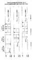
図2は、MTC端末のPUCCHの繰り返し送信によるPUCCHの衝突を示す図である。上記のように、MTC端末のカバレッジを拡張するために、カバレッジ拡張モードのMTC端末に対して、PDCCH及びPDSCHが繰り返し送信される。 FIG. 2 is a diagram illustrating a PUCCH collision due to repeated transmission of PUCCH of an MTC terminal. As described above, in order to extend the coverage of the MTC terminal, the PDCCH and the PDSCH are repeatedly transmitted to the MTC terminal in the coverage extension mode.
LTEシステム及びLTE−Advancedシステムでは、再送技術としてHARQ(Hybrid ARQ)が使用される。送達確認情報(ACK/NACK)を含むHARQフィードバックは、PUCCHで送信される。PDSCHの繰り返し送信に対応して、PUCCHも繰り返し送信される。なお、PDCCH、PDSCH、PUCCHのいずれかのみが繰り返し送信される場合もある。PUCCHは、PDSCHの繰り返し送信が終了した後の一定の時間後(例えば4ms後)に送信される。 In the LTE system and the LTE-Advanced system, HARQ (Hybrid ARQ) is used as a retransmission technique. HARQ feedback including acknowledgment information (ACK / NACK) is transmitted on PUCCH. Corresponding to the PDSCH repeated transmission, the PUCCH is also repeatedly transmitted. Note that only one of PDCCH, PDSCH, and PUCCH may be repeatedly transmitted. The PUCCH is transmitted after a certain time (for example, after 4 ms) after the repeated transmission of the PDSCH is completed.
図2において、MTC端末0のPUCCHのリソースは、nPUCCH0=nCCEi+NPUCCHにより求まる。nCCEiはPUCCHに対応するPDCCHの最初のCCEインデックスであり、MTC端末0に対しては、数フレーム前のPDCCHの繰り返し送信において使用されたCCEインデックスnCCEiが使用される。In FIG. 2, the PUCCH resource of MTC terminal 0 is obtained by nPUCCH0 = nCCEi + NPUCCH . nCCEi is the first CCE index of the PDCCH corresponding to the PUCCH, and for the MTC terminal 0, the CCE index nCCEi used in the repeated transmission of PDCCH several frames before is used.
一方、通常のLTE端末も同じカバレッジ内に存在し、MTC端末と同じ基地局(eNB:enhanced Node B)と通信する。LTE端末は、同一フレームで送信されたPDCCH及びPDSCHを受信して一定の時間(例えば4ms)後にPUCCHを送信する。LTE端末1のPUCCHのリソースは、nPUCCH1=nCCEi+NPUCCHにより求まる。nCCEiはPUCCHに対応するPDCCHの最初のCCEインデックスであり、LTE端末1に対しては、例えばFDD(Frequency Division Duplex)では4ms前のサブフレームのPDCCHにおいて使用されたCCEインデックスnCCEiが使用される。図2に示すように、MTC端末0のnCCEiとLTE端末1のnCCEiは同じになる可能性があり、この場合、PUCCHの衝突が生じる。同様に、MTC端末0によるPUCCHの繰り返し送信の間に、LTE端末2との間でPUCCHの衝突が生じる可能性がある。On the other hand, a normal LTE terminal also exists in the same coverage, and communicates with the same base station (eNB: enhanced Node B) as the MTC terminal. The LTE terminal receives the PDCCH and PDSCH transmitted in the same frame and transmits the PUCCH after a certain time (for example, 4 ms). The PUCCH resource of the
図3は、MTC端末のPUCCHの繰り返し送信によるPUCCHの衝突を示す図である。図3では、MTC端末同士がPUCCHを繰り返し送信した場合のPUCCHの衝突の様子を示している。特に、カバレッジ拡張モードのMTC端末は、PUCCHを送信する回数が増えるため、PUCCHの衝突の可能性は図2の場合に比べて高くなる。 FIG. 3 is a diagram illustrating a PUCCH collision caused by repeated transmission of the PUCCH of the MTC terminal. FIG. 3 shows a state of collision of PUCCHs when MTC terminals repeatedly transmit PUCCHs. In particular, the MTC terminal in the coverage extension mode increases the number of times of transmitting the PUCCH, so that the possibility of a PUCCH collision is higher than in the case of FIG.
図2及び図3では、MTC端末によるPUCCHの繰り返し送信によるPUCCHが衝突する様子を示しているが、このようなPUCCHの衝突は、PUCCHが繰り返し送信される場合に生じるだけでなく、PDCCHとPDSCHの送信タイミングが異なるユーザが混在することによっても生じる。 FIGS. 2 and 3 show a state in which PUCCH collides due to repeated transmission of PUCCH by an MTC terminal. However, such a PUCCH collision occurs not only when PUCCH is repeatedly transmitted, but also PDCCH and PDSCH. This also occurs when users with different transmission timings coexist.
図4に、PUCCHの衝突確率を示す。図4は、同じカバレッジ内に16個の端末が存在し、PDCCH、PDSCH及びPUCCHが同じ繰り返し回数(10回)を用いて送信される場合のシミュレーション結果を示している。MTC端末の数が増えるほど、PUCCHの衝突確率は高くなる。 FIG. 4 shows the PUCCH collision probability. FIG. 4 shows a simulation result when 16 terminals exist in the same coverage and PDCCH, PDSCH, and PUCCH are transmitted using the same number of repetitions (10 times). As the number of MTC terminals increases, the probability of PUCCH collision increases.
このようなPUCCHの衝突を回避又は低減するため、本発明の実施例では、以下の3つの手法を用いる。3つの手法のうちいずれかを組み合わせて適用してもよい。 In order to avoid or reduce such a PUCCH collision, the embodiment of the present invention uses the following three methods. Any one of the three methods may be applied in combination.
(1)第1の手法
第1の手法では、PUCCHの衝突を回避するため、基地局において、PUCCHの衝突が生じないように、PDCCHのリソースを割り当てる。上記のように、PUCCHのリソースは、PDCCHのリソース割り当て位置(nCCEi)及び上位レイヤのシグナリングにより設定されるPUCCHリソースのスタートインデックス(NPUCCH)により求められる。PDCCHのリソース割り当て位置(nCCEi)に基づく調整では、基地局は、過去のPDCCHのリソース割り当て情報を考慮して、HARQフィードバックを送信するサブフレームが同一となるPDCCH間で同じnCCEが用いられないように、PDCCHのリソースを割り当てる。あるいは、予約されたPUCCHのリソース割り当て情報を考慮して、同一サブフレーム内で異なる端末用のPUCCHに対して同一のリソースを重複して割り当てないようPDCCHのリソースを割り当てる。また、上位レイヤのシグナリングにより設定されるPUCCHリソースのスタートインデックス(NPUCCH)に基づく調整では、基地局は、MTC端末に固有のNPUCCHを設定し、同一サブフレーム内で異なる端末用のPUCCHに対して同一のリソースを重複して割り当てないようPDCCHのリソースを割り当てる。(1) First Method In the first method, in order to avoid a PUCCH collision, a base station allocates PDCCH resources so that a PUCCH collision does not occur. As described above, the PUCCH resource is determined by the PDCCH resource allocation position (nCCEi ) and the PUCCH resource start index (NPUCCH ) set by higher layer signaling. In the adjustment based on the PDCCH resource allocation position (nCCEi ), the base station uses the same nCCE between PDCCHs having the same subframe in which HARQ feedback is transmitted in consideration of the past PDCCH resource allocation information. PDCCH resources are allocated so as not to be present. Alternatively, in consideration of reserved PUCCH resource allocation information, PDCCH resources are allocated so that the same resource is not allocated to different PUCCHs for different terminals in the same subframe. Also, in the adjustment based on the start index (NPUCCH ) of the PUCCH resource set by higher layer signaling, the base station sets NPUCCH specific to the MTC terminal, and sets the PUCCH for different terminals in the same subframe. On the other hand, PDCCH resources are allocated so that the same resource is not allocated twice.
(2)第2の手法
第2の手法では、PUCCHの衝突を低減するため、MTC端末は、PDSCHに対する再送判定を行い、再送が必要ない場合、PUCCHではACKを送信せず、再送が必要な場合、NACKを送信する。すなわち、送達確認情報(ACK/NACK)のうちNACKのみを送信する。受信環境のよいMTC端末は、PUCCHを送信しないため、PUCCHの衝突が低減される。(2) Second Method In the second method, in order to reduce PUCCH collision, the MTC terminal performs retransmission determination on the PDSCH, and when retransmission is not necessary, the PUCCH does not transmit ACK and requires retransmission. If so, send a NACK. That is, only NACK is transmitted among the acknowledgment information (ACK / NACK). Since the MTC terminal having a good reception environment does not transmit the PUCCH, the PUCCH collision is reduced.
(3)第3の手法
第3の手法では、PUCCHの衝突を回避するため、基地局は、MTC端末に使用させるPUCCHのリソースを明示的又は非明示的に通知する。一実施例では、基地局は、PUCCHのリソースの複数の候補を端末に予めシグナリングする。基地局は、予めシグナリングしたPUCCHのリソースの候補の中でMTC端末に使用させるPUCCHのリソースを決定し、これを明示的に通知するため、PUCCHのリソースを決定するためのインジケータ(ARI:ACK Indicator field)をMTC端末に送信する。MTC端末は、PUCCHのリソースを決定するためのインジケータを受信し、受信したインジケータに従ってPUCCHを送信する。また、基地局は、上述した式(1)にオフセットを追加し、当該オフセットを通知するという非明示的な通知によって、MTC端末に使用させるPUCCHのリソースをMTC端末に通知してもよい。(3) Third Method In the third method, in order to avoid a PUCCH collision, the base station explicitly or implicitly notifies the PUCCH resource used by the MTC terminal. In one embodiment, the base station previously signals a plurality of PUCCH resource candidates to the terminal. The base station determines the PUCCH resource to be used by the MTC terminal among the PUCCH resource candidates signaled in advance, and explicitly notifies this, so that an indicator (ARI: ACK Indicator) for determining the PUCCH resource is determined. field) to the MTC terminal. The MTC terminal receives the indicator for determining the PUCCH resource, and transmits the PUCCH according to the received indicator. Further, the base station may notify the MTC terminal of PUCCH resources to be used by the MTC terminal by an implicit notification of adding an offset to the above-described equation (1) and notifying the offset.
それぞれの手法について、以下に詳細に説明する。 Each method will be described in detail below.
<第1の手法>
図5に、本発明の実施例の第1の手法に従ってPUCCHの衝突を回避する様子を示す。基地局は、基地局と通信する端末に対してPDCCH及びPDSCHのリソースを割り当てるため、基地局は、どのリソースにPDCCHを割り当てたか(PDCCHのリソース割り当て情報)を認識しており、その結果、どのリソースでPUCCHを受信するか(PUCCHのリソース割り当て情報)も認識している。<First method>
FIG. 5 shows how a PUCCH collision is avoided according to the first method of the embodiment of the present invention. Since the base station allocates PDCCH and PDSCH resources to terminals communicating with the base station, the base station recognizes to which resource the PDCCH is allocated (PDCCH resource allocation information). It also recognizes whether PUCCH is received by the resource (resource allocation information of PUCCH).
従って、MTC端末が異なるサブフレームによりPDSCHとPDCCHとを受信する場合、基地局は、PDCCHのリソース割り当て情報又はPUCCHのリソース割り当て情報を用いて、PUCCHの衝突が生じないようにPDCCHのリソースを割り当てる。例えば、MTC端末に対して複数サブフレームにPDCCH及びPDSCHを割り当てており、複数のサブフレームでPUCCHを受信することになっているものとする。このときにLTE端末が通信する場合、LTE端末には、MTC端末が送信するPUCCHとは異なるリソースでPUCCHを送信するように、PDCCHのリソースを割り当てる。 Therefore, when the MTC terminal receives the PDSCH and the PDCCH by different subframes, the base station allocates the PDCCH resource so that the PUCCH collision does not occur using the PDCCH resource allocation information or the PUCCH resource allocation information. . For example, it is assumed that a PDCCH and a PDSCH are allocated to a plurality of subframes for an MTC terminal, and a PUCCH is to be received in a plurality of subframes. When the LTE terminal communicates at this time, the PDCCH resource is allocated to the LTE terminal so that the PUCCH is transmitted using a resource different from the PUCCH transmitted by the MTC terminal.
例えば、図5において、MTC端末が複数のサブフレームでnPUCCH0=nCCEi+NPUCCHにより示されるリソースを用いてPUCCHを送信する場合、MTC端末がPUCCHを送信するサブフレームで同じnCCEiが用いられないように、LTE端末1には、異なるnCCEjで示されるPDCCHのリソースを割り当て、LTE端末2には、異なるnCCEkで示されるPDCCHのリソースを割り当てる。For example, in FIG. 5, when the MTC terminal transmits PUCCH using resources indicated by nPUCCH0 = nCCEi + NPUCCH in a plurality of subframes, the same nCCEi is the same in the subframe in which the MTC terminal transmits PUCCH. as not used, the
図6は、複数のMTC端末が通信する場合のPUCCHの衝突を回避する様子を示す。この場合も、図5で説明したのと同様に、基地局は、PDCCHのリソース割り当て情報又はPUCCHのリソース割り当て情報を用いて、PUCCHの衝突が生じないようにPDCCHのリソースを割り当てる。 FIG. 6 illustrates a situation in which a PUCCH collision is avoided when a plurality of MTC terminals communicate. Also in this case, as described with reference to FIG. 5, the base station uses the PDCCH resource allocation information or the PUCCH resource allocation information to allocate PDCCH resources so that no PUCCH collision occurs.
例えば、図6において、MTC端末0が複数のサブフレームでnPUCCH0=nCCEi+NPUCCHにより示されるリソースを用いてPUCCHを送信する場合、MTC端末がPUCCHを送信するサブフレームで同じnCCEiが用いられないように、MTC端末1には、異なるnCCEjを用いてnPUCCH1=nCCEj+NPUCCHで示されるPDCCHのリソースを割り当て、LTE端末2には、異なるnCCEkを用いてnPUCCH2=nCCEk+NPUCCH示されるPDCCHのリソースを割り当てる。For example, in FIG. 6, when MTC terminal 0 transmits PUCCH using resources indicated by nPUCCH0 = nCCEi + NPUCCH in a plurality of subframes, the same nCCEi is transmitted in the subframe in which the MTC terminal transmits PUCCH. as is not used, the
また、MTC端末が複数のサブフレームでnPUCCH0=nCCEi+NPUCCHにより示されるリソースを用いてPUCCHを送信する場合、MTC端末がPUCCHを送信するサブフレームで同じNPUCCHが用いられないように、LTE端末には、異なるNPUCCHで示されるPDCCHのリソースを割り当てる。当該NPUCCHは、MTC端末に固有の値に設定されてもよい。また、MTC端末間のPUCCHの衝突については、例えば、モード種別に固有の値(NPUCCHlowcostMCE, NPUCCHenhancedcoverageMCE)がNPUCCHに設定されてもよい。 図7Aは、本発明の実施例に係る基地局(eNB)10の構成図である。基地局10は、伝送路インタフェース101と、ベースバンド信号処理部103と、呼処理部105と、送受信部107と、アンプ部109とを有する。Also, when the MTC terminal transmits PUCCH using resources indicated by nPUCCH0 = nCCEi + NPUCCH in a plurality of subframes, the same NPUCCH is not used in the subframe in which the MTC terminal transmitsPUCCH.Furthermore , PDCCH resources indicated by different NPUCCHs are allocated to LTE terminals. The NPUCCH may be set to a value specific to the MTC terminal. Also, for PUCCH collisions between MTC terminals, for example, values (NPUCCHlowcostMCE , NPUCCHenhancedcoverageMCE ) specific to the mode type may be set to NPUCCH . FIG. 7A is a block diagram of the base station (eNB) 10 according to the embodiment of the present invention. The
下りリンクにより基地局10から移動局に送信されるデータは、上位局装置から伝送路インターフェース101を介してベースバンド信号処理部103に入力される。 Data transmitted from the
ベースバンド信号処理部103は、PDCP(Packet Data Convergence Protocol)レイヤの処理、データの分割・結合、RLC(Radio Link Control)再送制御の送信処理などのRLCレイヤの送信処理、MAC(Medium Access Control)再送制御、例えば、HARQ(Hybrid Automatic Repeat reQuest)の送信処理、スケジューリング、伝送フォーマット選択、チャネル符号化、逆高速フーリエ変換(IFFT:Inverse Fast Fourier Transform)処理、プリコーディング処理が行われる。また、下りリンク制御チャネルである物理下りリンク制御チャネルの信号に関しても、チャネル符号化や逆高速フーリエ変換等の送信処理が行われる。 The baseband
呼処理部105は、通信チャネルの設定や解放等の呼処理や、基地局10の状態管理や、無線リソースの管理を行う。 The
送受信部107は、ベースバンド信号処理部103から出力されたベースバンド信号を無線周波数帯に周波数変換する。アンプ部109は周波数変換された送信信号を増幅して送受信アンテナへ出力する。なお、複数の送受信アンテナが用いられる場合、複数の送受信部107及びアンプ部109が存在してもよい。 The transmission /
一方、上りリンクにより移動局から基地局10に送信される信号については、送受信アンテナで受信された無線周波数信号がアンプ部109で増幅され、送受信部107で周波数変換されてベースバンド信号に変換され、ベースバンド信号処理部103に入力される。 On the other hand, for the signal transmitted from the mobile station to the
ベースバンド信号処理部103は、上りリンクで受信したベースバンド信号に含まれるデータに対して、FFT処理、IDFT処理、誤り訂正復号、MAC再送制御の受信処理、RLCレイヤ、PDCPレイヤの受信処理を行う。復号された信号は伝送路インターフェース101を介して上位局装置に転送される。 The baseband
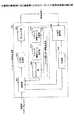
図7Bは、本発明の実施例に係る基地局10におけるベースバンド信号処理部103の構成図である。ベースバンド信号処理部103は、制御部1031と、下りリンク(DL)信号生成部1032と、マッピング部1033と、スケジューリング部1034と、下りリンク制御リソース決定部1035と、上りリンク制御リソース決定部1036と、リソース割り当て情報記憶部1037と、上りリンク(UL)信号復号部1038と、判定部1039とを有する。 FIG. 7B is a configuration diagram of the baseband
制御部1031は、ベースバンド信号処理部103の全体の管理を行う。下りリンクにより移動局に送信する信号については、伝送路インタフェース101から入力されたデータをDL信号生成部1032に入力する。上りリンクにより移動局から受信した信号については、UL信号復号部1038で復号されたデータを伝送路インタフェース101に入力する。また、制御部1031は、HARQ等の再送処理を行う。 The
DL信号生成部1032は、移動局に送信する信号を生成する。移動局に送信する信号には、データ及び制御情報が含まれ、データは主にPDSCHで送信され、PDSCHを受信するために必要な割り当て情報は、PDCCHで送信される。 The DL
マッピング部1033は、PDSCHで送信するデータ及びPDCCHで送信する制御情報をスケジューリング部1034及び下りリンク制御リソース決定部1035で決定されたリソースに配置する。
スケジューリング部1034は、PDSCHで移動局に送信するデータのスケジューリングを行う。例えば、スケジューリング部1034は、送達確認情報、チャネル推定値及びチャネル品質等を考慮しながら、PDSCHにて送信するデータをスケジューリングする。 The
下りリンク制御リソース決定部1035は、PDCCHに対するリソースを割り当てる。PDCCHに割り当て可能なリソースは予め決められており、下りリンク制御リソース決定部1035は、予め決められたリソースの中からPDCCHのリソースを割り当てる。 The downlink control
上りリンク制御リソース決定部1036は、PUCCHに対するリソースを割り当てる。前述のように、PUCCHのリソースは、以下の式(1)により求められる。 The uplink control
nPUCCH=nCCE+NPUCCH (1)
リソース割り当て情報記憶部1037は、各種のチャネルのリソース割り当て情報を格納する。具体的には、リソース割り当て情報記憶部105は、スケジューリング部1034でスケジューリングされたPDSCHのリソース割り当て情報を記憶すると共に、下りリンク制御リソース決定部1035で決定されたPDCCHのリソース割り当て情報を記憶する。また、リソース割り当て情報記憶部1037は、上りリンク制御リソース決定部1036で決定されたPUCCHのリソース割り当て情報も記憶する。nPUCCH = nCCE + NPUCCH (1)
The resource allocation information storage unit 1037 stores resource allocation information for various channels. Specifically, the resource allocation
UL信号復号部1038は、上りリンクにより移動局から受信した信号を復号する。PUSCH(Physical Uplink Shared Channel)で受信したデータは、伝送路インタフェース101に提供するために制御部1031に入力し、PUCCHで受信した送達確認情報(ACK/NACK)も、HARQ等の再送処理のために制御部1031に入力する。 The UL
判定部1039は、PUSCHで受信した信号の再送判定を行う。PUSCHの受信に成功した場合、再送の必要がないことを示す送達確認情報(ACK)を生成し、PUSCHの受信に失敗した場合、再送の必要があることを示す送達確認情報(NACK)を生成する。 The
本発明の実施例の第1の手法における基地局10の各機能部の動作については、以下に図9を参照して説明する。 The operation of each functional unit of the
図8Aは、本発明の実施例に係る移動局(MTC端末及びLTE端末)20の構成図である。移動局20は、アプリケーション部201と、ベースバンド信号処理部203と、送受信部205と、アンプ部207とを有する。 FIG. 8A is a configuration diagram of the mobile station (MTC terminal and LTE terminal) 20 according to the embodiment of the present invention. The
下りリンクのデータについては、送受信アンテナで受信された無線周波数信号がアンプ部207で増幅され、送受信部205で周波数変換されてベースバンド信号に変換される。このベースバンド信号は、ベースバンド信号処理部203でFFT処理や、誤り訂正復号、再送制御の受信処理等がなされる。この下りリンクのデータのうち、下りリンクのデータは、アプリケーション部201に転送される。アプリケーション部201は、物理レイヤやMACレイヤより上位のレイヤに関する処理等を行う。 For downlink data, a radio frequency signal received by the transmission / reception antenna is amplified by the
一方、上りリンクのデータは、アプリケーション部201からベースバンド信号処理部203に入力される。ベースバンド信号処理部203においては、再送制御の送信処理や、チャネル符号化、DFT処理、IFFT処理を行う。送受信部205は、ベースバンド信号処理部203から出力されたベースバンド信号を無線周波数帯に変換する。その後、アンプ部207で増幅されて送受信アンテナより送信される。 On the other hand, uplink data is input from the
図8Bは、本発明の実施例に係る移動局20におけるベースバンド信号処理部203の構成図である。ベースバンド信号処理部203は、制御部2031と、上りリンク(UL)信号生成部2032と、マッピング部2033と、下りリンク(DL)信号生成部234と、判定部2035とを有する。 FIG. 8B is a configuration diagram of the baseband
制御部2031は、ベースバンド信号処理部203の全体の管理を行う。上りリンクにより基地局に送信する信号については、アプリケーション部201から入力されたデータをUL信号生成部2032に入力する。下りリンクにより基地局から受信した信号については、DL信号復号部2034で受信処理されたデータをアプリケーション部201に入力する。また、制御部2031は、HARQ等の再送処理を行う。 The
UL信号生成部2032は、基地局に送信する信号を生成する。基地局に送信する信号には、データ及び制御情報が含まれ、データは主にPUSCHで送信される。また、基地局からPDSCHで受信したデータの送達確認情報(ACK/NACK)はPUCCHで送信される。 The UL
マッピング部2033は、PUSCHで送信するデータを基地局のスケジューリング部1034で決定されたリソースに配置する。また、送達確認情報(ACK/NACK)が配置されるPUCCHのリソースは、前述のように、対応するPDCCHのリソースから以下の式(1)により求められる。 The
nPUCCH=nCCE+NPUCCH (1)
DL信号復号部2034は、下りリンクにより基地局から受信した信号を復号し、PDSCHで受信したデータは、アプリケーション部201に提供するために制御部2031に入力する。nPUCCH = nCCE + NPUCCH (1)
The DL
判定部2035は、PDSCHで受信した信号の再送判定を行う。PDSCHの受信に成功した場合、再送の必要がないことを示す送達確認情報(ACK)を生成し、PUSCHの受信に失敗した場合、再送の必要があることを示す送達確認情報(NACK)を生成する。 The
なお、本発明の実施例の第1の手法では、基地局においてPUCCHの衝突が生じないようにPDCCHのリソースを割り当てる、すなわち、PUCCHの衝突が生じないように式(1)のnCCE及びNPUCCHを設定するため、移動局20の各機能部には、上記の動作以外に特別な動作は必要ない。In the first method of the embodiment of the present invention, PDCCH resources are allocated so that no PUCCH collision occurs in the base station, that is, nCCE and N in Equation (1) so that no PUCCH collision occurs.In order to setPUCCH , each functional unit of the
図9は、本発明の実施例の第1の手法による基地局10における送信方法のフローチャートである。 FIG. 9 is a flowchart of a transmission method in the
リソース割り当て情報記憶部1037は、PDCCHのリソース割り当て情報又はPUCCHのリソース割り当て情報を格納している。PDCCHのリソース割り当て情報は、上記の式(1)のnCCEでもよく、他のPDCCHのリソース割り当て位置を示す値でもよい。また、PUCCHのリソース割り当て情報は、上記の式(1)のnPUCCH及び/又はNPUCCHでもよく、他のPUCCHのリソース割り当て位置を示す値でもよい。The resource allocation information storage unit 1037 stores PDCCH resource allocation information or PUCCH resource allocation information. The PDCCH resource allocation information may be the nCCE of the above equation (1), or may be a value indicating the resource allocation position of another PDCCH. Also, the PUCCH resource allocation information may be nPUCCH and / or NPUCCH in the above equation (1), or may be a value indicating the resource allocation position of another PUCCH.
下りリンク制御リソース決定部1035は、リソース割り当て情報記憶部1037からPDCCH又はPUCCHのリソース割り当て情報を取得する(ステップS101)。例えば、あるサブフレームにおいて移動局にデータを送信する場合、そのサブフレームに対応するPUCCHでMTC端末がPUCCHを送信するか否かを確認し、MTC端末がPUCCHを送信する場合、MTC端末のPUCCHのリソース割り当て情報を取得する。 The downlink control
下りリンク制御リソース決定部1035は、取得されたリソース割り当て情報を参照して、PUCCHの衝突が生じないようにPDCCHのリソースを割り当てる(ステップS103)。例えば、あるサブフレームに対応するPUCCHでMTC端末がPUCCHを送信する場合、PUCCHのリソース割り当て位置が重複しないように、PDCCHのリソースを割り当てる。 The downlink control
PDCCH及びPUSCHは、マッピング部1033においてリソースブロックにマッピングされて移動局に送信される(ステップS105)。 PDCCH and PUSCH are mapped to resource blocks in
このようにすることで、端末間でのPUCCHの衝突が回避できる。 By doing in this way, the collision of PUCCH between terminals can be avoided.
<第2の手法>
図10に、本発明の実施例の第2の手法に従ってPUCCHの衝突を低減する様子を示す。LTE端末及びMTC端末は、受信品質を向上させるために再送技術を使用する。LTEシステム及びLTE−Advancedシステムでは、再送技術としてHARQが使用される。HARQでは、再送判定の結果を示す送達確認情報として、ACKとNACKとが規定されているが、第2の手法では、LTE端末は、PDSCHの再送判定の結果を示す送達確認情報(ACK/NACK)を送信する。一方、MTC端末は、送達確認情報(ACK/NACK)のうちNACKのみを送信する。<Second method>
FIG. 10 shows how the PUCCH collision is reduced according to the second method of the embodiment of the present invention. LTE terminals and MTC terminals use retransmission techniques to improve reception quality. In the LTE system and the LTE-Advanced system, HARQ is used as a retransmission technique. In HARQ, ACK and NACK are defined as delivery confirmation information indicating the result of retransmission determination. However, in the second technique, the LTE terminal transmits delivery confirmation information (ACK / NACK) indicating the result of PDSCH retransmission determination. ). On the other hand, the MTC terminal transmits only NACK in the delivery confirmation information (ACK / NACK).
図10において、カバレッジ拡張モードのMTC端末0は、受信環境のよい位置に在圏するものとする。この場合、MTC端末0はPDSCHの繰り返し送信の受信に成功するため、PUCCH(ACK)を送信しない。 In FIG. 10, it is assumed that the MTC terminal 0 in the coverage extension mode is located in a position where the reception environment is good. In this case, since the MTC terminal 0 succeeds in receiving the PDSCH repetitive transmission, the MTC terminal 0 does not transmit the PUCCH (ACK).
MTC端末0はPUCCHを送信しないため、LTE端末1がnPUCCH1=nCCEi+NPUCCHにより示されるリソースを用いてPUCCHを送信するときにPUCCHの衝突は生じない。同様に、LTE端末2がnPUCCH2=nCCEi+NPUCCHにより示されるリソースを用いてPUCCHを送信するときにPUCCHの衝突は生じない。ただし、MTC端末0の受信環境が悪く、MTC端末0がNACKを送信する可能性がある場合、PUCCHの衝突を完全に回避することはできない。Since MTC terminal 0 does not transmit PUCCH, there is no PUCCH collision when
図11は、複数のMTC端末が通信する場合のPUCCHの衝突を低減する様子を示す。この場合も、図10で説明したのと同様に、MTC端末は、送達確認情報(ACK/NACK)のうちNACKのみを送信する。例えば、図11において、MTC端末0及びMTC端末2が受信環境のよい位置に在圏し、MTC端末1が受信環境の悪い位置い在圏するものとする。この場合、カバレッジ拡張モードのMTC端末0及びMTC端末2は、PUCCHを送信しないため、MTC端末1がnPUCCH1=nCCEi+NPUCCHにより示されるリソースを用いてPUCCHを送信するときにPUCCHの衝突は生じない。FIG. 11 shows a manner of reducing PUCCH collisions when a plurality of MTC terminals communicate. Also in this case, the MTC terminal transmits only NACK in the acknowledgment information (ACK / NACK), as described with reference to FIG. For example, in FIG. 11, it is assumed that the MTC terminal 0 and the
本発明の実施例の第2の手法における基地局10及び移動局20は、図7A、図7B、図8A及び図8Bと同様に構成される。本発明の実施例の第2の手法における基地局10及び移動局20の各機能部の動作については、以下に図12を参照して説明する。 The
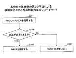
図12は、本発明の実施例の第2の手法による移動局20における再送制御方法のフローチャートである。 FIG. 12 is a flowchart of a retransmission control method in the
DL信号復号部2034は、PDCCHで通知された制御情報を復号し、割り当て情報を取得する。また、DL信号復号部2034は、PDCCHで通知された割り当て情報に基づいて、PDSCHで送信されたデータを復号する。(ステップS201)。 The DL
判定部2035は、PDSCHに対して再送が必要であるか否かを判定する(ステップS203)。PDSCHの受信に失敗した場合、再送の必要があることを示す送達確認情報(NACK)を生成する。 The
再送の必要がある場合、再送の必要があることを示す送達確認情報(NACK)は、チャネル符号化、変調等の処理を施され、以下の式(1)により求められるリソースを用いてPUCCHで送信される(ステップS205)。 When retransmission is necessary, acknowledgment information (NACK) indicating that retransmission is necessary is subjected to processing such as channel coding and modulation, and PUCCH is performed using resources obtained by the following equation (1). It is transmitted (step S205).
nPUCCH=nCCE+NPUCCH (1)
なお、PDSCHの受信に成功した場合、PUCCHでは再送の必要がないことを示す送達確認情報(ACK)は送信されない(ステップS207)ため、判定部2035は、送達確認情報(ACK)を生成せずに処理を終了してもよい。本発明の実施例の第2の手法では、移動局20においてACKを送信しないため、基地局10は、移動局が再送プロセスにおいて応答なしの状態(DTX)であるか、受信が成功した状態(ACK)であるかを把握することができない。従って、基地局10において、移動局の再送を制御する制御部1031は、PUCCHの応答がない場合、移動局20がPDSCHの受信に成功したものとみなす(ACKとみなす)。nPUCCH = nCCE + NPUCCH (1)
Note that if the PDSCH is successfully received, the delivery confirmation information (ACK) indicating that there is no need for retransmission is not transmitted on the PUCCH (step S207), so the
なお、MTC端末は、PUCCHを送信するサブフレームにおいてPUSCHがスケジューリングされており、UCI(Uplink Control Information)がPUSCHにより送信される場合は再送の必要がないことを示す送達確認情報(ACK)を送信すると仮定してもよいし、PUCCHと共通の動作として再送の必要があることを示す送達確認情報(NACK)のみ送信するとしてもよい。 The MTC terminal transmits acknowledgment information (ACK) indicating that retransmission is not required when PUSCH is scheduled in a subframe in which PUCCH is transmitted and UCI (Uplink Control Information) is transmitted by PUSCH. Then, it may be assumed that only the acknowledgment information (NACK) indicating that retransmission is necessary as a common operation with PUCCH may be transmitted.
このようにすることで、端末間でのPUCCHの衝突が低減できる。 By doing in this way, the collision of PUCCH between terminals can be reduced.
<第3の手法>
図13に、本発明の実施例の第3の手法に従ってPUCCHの衝突を回避する様子を示す。<Third method>
FIG. 13 shows how a PUCCH collision is avoided according to the third method of the embodiment of the present invention.
基地局は、端末に使用させるPUCCHのリソース又はPUCCHのリソースの複数の候補を端末に予め上位レイヤのシグナリング(例えばRRC(Radio Resource Control)シグナリング)により通知する。基地局は、基地局と通信する端末に対してPDCCH及びPDSCHのリソースを割り当てるため、基地局は、どのリソースにPDCCHを割り当てたか(PDCCHのリソース割り当て情報)を認識しており、その結果、どのリソースでPUCCHを受信するか(PUCCHのリソース割り当て情報)も認識している。 The base station notifies the terminal of PUCCH resources to be used by the terminal or a plurality of PUCCH resource candidates in advance by higher layer signaling (for example, RRC (Radio Resource Control) signaling). Since the base station allocates PDCCH and PDSCH resources to terminals communicating with the base station, the base station recognizes to which resource the PDCCH is allocated (PDCCH resource allocation information). It also recognizes whether PUCCH is received by the resource (resource allocation information of PUCCH).
MTC端末が通信することによりPUCCHの衝突が生じる可能性がある場合、基地局は、PDCCH及びPUCCHのリソース割り当て情報に基づき、MTC端末に使用させるPUCCHのリソースをMTC端末に通知する。当該通知は、RRCシグナリングにより送信され、各MTC端末に対して具体的なPUCCHのリソースを通知してもよい。あるいは、DCI(Downlink Control Information)内のあるフィールドによって、具体的なPUCCHのリソースを通知してもよい。当該フィールドは新たに定義されてもよいし、既存のフィールドを利用してもよい。当該通知を受信すると、MTC端末は、通知されたリソースを使用してPUCCHを送信する。 When there is a possibility that a PUCCH collision may occur due to communication by the MTC terminal, the base station notifies the MTC terminal of PUCCH resources to be used by the MTC terminal based on the PDCCH and PUCCH resource allocation information. The said notification may be transmitted by RRC signaling and may notify each MTC terminal of the concrete PUCCH resource. Alternatively, a specific PUCCH resource may be notified by a certain field in DCI (Downlink Control Information). The field may be newly defined or an existing field may be used. When receiving the notification, the MTC terminal transmits the PUCCH using the notified resource.
あるいは、基地局は、予めシグナリングしたPUCCHのリソースの候補の中でMTC端末に使用させるPUCCHのリソースを決定し、PUCCHのリソースを決定するためのインジケータ(ARI)をMTC端末に送信する。MTC端末に送信されるARIは、予めシグナリングにより通知されたPUCCHのリソースの候補の中でどれを用いるかを示す。 例えば、4パターンのPUCCHのリソースの候補が存在する場合、4パターンのうちどれを用いるかは2ビットの情報量で定義することができる。2ビットの情報量は、既存の仕様で定義されているDCI(Downlink Control Information)の中のARI(ACK Indicator field)を使用してMTC端末に通知されてもよい。MTC端末はあらかじめどのDCIによりARIが通知されるかを知っているものとする。例えば、ARIは割り当て情報(DL assignment)を送信するDCIの一部を使用してMTC端末に通知されてもよい。 Alternatively, the base station determines a PUCCH resource to be used by the MTC terminal among PUCCH resource candidates signaled in advance, and transmits an indicator (ARI) for determining the PUCCH resource to the MTC terminal. The ARI transmitted to the MTC terminal indicates which of the PUCCH resource candidates notified in advance by signaling is to be used. For example, when there are four patterns of PUCCH resource candidates, which of the four patterns is used can be defined by a 2-bit information amount. The 2-bit information amount may be notified to the MTC terminal using an ARI (ACK Indicator field) in DCI (Downlink Control Information) defined in the existing specification. MTC terminal is assumed to know ARI is notified in advance by any DCI. For example, the ARI may be notified to the MTC terminal using a part of DCI that transmits assignment information (DL assignment).
MTC端末は、PUCCHのリソースを決定するためのインジケータを受信し、受信したインジケータに従ってPUCCHを送信する。 The MTC terminal receives the indicator for determining the PUCCH resource, and transmits the PUCCH according to the received indicator.
例えば、図13において、カバレッジ拡張モードのMTC端末0が複数のサブフレームでPUCCHを送信する場合、基地局は、PUCCHの衝突が生じないように、PUCCHのための具体的なリソースを通知するか、あるいは、予めシグナリングにより通知されたPUCCHのリソースの候補の中でどれを用いるかを示すARIをMTC端末0に通知する。MTC端末0は、式(1)により求められたPUCCHのリソースではなく、通知された具体的なリソースを使用してPUCCHを送信するか、あるいは、ARIにより通知された情報を用いて、PUCCHのリソースを判定し、PUCCHを送信する。 For example, in FIG. 13, when MTC terminal 0 in coverage extension mode transmits PUCCH in a plurality of subframes, the base station reports specific resources for PUCCH so that PUCCH collision does not occur. Alternatively, the MTC terminal 0 is notified of the ARI indicating which of the PUCCH resource candidates notified in advance by signaling is to be used. The MTC terminal 0 transmits the PUCCH using the notified specific resource instead of the PUCCH resource obtained by the equation (1), or uses the information notified by the ARI, and uses the PUCCH information. A resource is determined and PUCCH is transmitted.
図14は、複数のMTC端末が通信する場合のPUCCHの衝突を回避する様子を示す。この場合も、図13で説明したのと同様に、基地局は、PUCCHの衝突が生じないように、PDCCH及びPUCCHのリソース割り当て情報に基づき決定されたPUCCHのリソースをMTC端末に通知するか、あるいは、予めシグナリングにより通知されたPUCCHのリソースの候補の中でどれを用いるかを示すARIをMTC端末に通知する。このため、複数のMTC端末が同時に通信する場合であっても、PUCCHの衝突が回避できる。 FIG. 14 illustrates a situation in which a PUCCH collision is avoided when a plurality of MTC terminals communicate. Also in this case, the base station notifies the MTC terminal of the PUCCH resource determined based on the PDCCH and PUCCH resource allocation information so that the PUCCH collision does not occur, as described in FIG. Alternatively, the MTC terminal is notified of the ARI indicating which of the PUCCH resource candidates notified in advance by signaling is to be used. For this reason, even when a plurality of MTC terminals communicate simultaneously, a PUCCH collision can be avoided.
本発明の実施例の第3の手法における基地局10及び移動局20は、図7A、図7B、図8A及び図8Bと同様に構成される。本発明の実施例の第3の手法における基地局10及び移動局20の各機能部の動作については、以下に図15及び図16を参照して説明する。 The
図15は、本発明の実施例の第3の手法による基地局10における送信方法のフローチャートである。 基地局10は、PUCCHのリソースの複数の候補を端末に予め上位レイヤのシグナリングにより通知する(ステップS301)。 FIG. 15 is a flowchart of a transmission method in the
リソース割り当て情報記憶部1037は、PDCCHのリソース割り当て情報又はPUCCHのリソース割り当て情報を格納している。PDCCHのリソース割り当て情報は、上記の式(1)のnCCEでもよく、他のPDCCHのリソース割り当て位置を示す値でもよい。また、PUCCHのリソース割り当て情報は、上記の式(1)のnPUCCHでもよく、他のPUCCHのリソース割り当て位置を示す値でもよい。The resource allocation information storage unit 1037 stores PDCCH resource allocation information or PUCCH resource allocation information. The PDCCH resource allocation information may be the nCCE of the above equation (1), or may be a value indicating the resource allocation position of another PDCCH. Also, the PUCCH resource allocation information may be the nPUCCH in the above equation (1), or may be a value indicating the resource allocation position of another PUCCH.
下りリンク制御リソース決定部1035は、リソース割り当て情報記憶部1037からPDCCH又はPUCCHのリソース割り当て情報を取得する(ステップS303)。例えば、複数のサブフレームにおいてMTC端末にデータを送信する場合、複数のサブフレームにそれぞれ対応するPUCCHで他の端末がPUCCHを送信するか否かを確認し、他の端末がPUCCHを送信する場合、PUCCHのリソース割り当て情報を取得する。 The downlink control
下りリンク制御リソース決定部1035は、取得されたリソース割り当て情報を参照して、MTC端末へのPDCCHの割り当てに伴い、PUCCHの衝突が生じ得るか否かを確認する。下りリンク制御リソース決定部1035は、PUCCHの衝突が生じないように、MTC端末のPUCCHのリソースを決定する(ステップS307)。決定されたPUCCHのリソースをMTC端末に通知するか、あるいは、PUCCHのリソースを決定するためのインジケータは、DL信号生成部1032において制御情報として生成され、PDCCHでMTC端末に送信される(ステップS309)。上記のように、PUCCHのリソースを決定するためのインジケータは、予め上位レイヤのシグナリングにより通知されたPUCCHのリソースの候補のうちどれを用いるかを示す値である。 The downlink control
図16は、本発明の実施例の第3の手法による移動局20における再送制御方法のフローチャートである。 FIG. 16 is a flowchart of a retransmission control method in the
移動局20は、PUCCHのリソースの複数の候補を予め上位レイヤのシグナリングにより受信しているものとする。DL信号復号部2034は、このPUCCHのリソースの候補の中でPUCCHのリソースを決定するためのインジケータを受信して復号するか、使用すべきPUCCHのリソースを基地局から通知される(ステップS401)。 It is assumed that the
また、DL信号復号部2034は、基地局からPDSCHで送信されたデータを受信する(ステップS403)。 Also, the DL
なお、ステップS401及びステップS403の順序に関して特に制限はなく、ステップS401の後にステップS403が実行されてもよく、ステップS403の前にステップS403が実行されてもよく、ステップS401とステップS403とが同時に(同一のサブフレームで)実行されてもよい。 Note that there is no particular limitation on the order of step S401 and step S403, step S403 may be executed after step S401, step S403 may be executed before step S403, and step S401 and step S403 are performed simultaneously. May be performed (in the same subframe).
判定部2035は、PDSCHに対して再送が必要であるか否かを判定する(ステップS405)。PDSCHの受信に失敗した場合、再送の必要があることを示す送達確認情報(NACK)を生成する。PDSCHの受信に成功した場合、再送の必要がないことを示す送達確認情報(ACK)を生成する。 The
送達確認情報(ACK/NACK)は、マッピング部2033で通知されたPUCCHのリソースを割り当てられるか、あるいは、受信したインジケータに従ってマッピング部2033でPUCCHのリソースを割り当てられ、PUCCHで送信される(ステップS407)。 The acknowledgment information (ACK / NACK) is assigned the PUCCH resource notified by the
このようにすることで、端末間でのPUCCHの衝突が回避できる。 By doing in this way, the collision of PUCCH between terminals can be avoided.
なお、上記の説明では、ARIにより、予め上位レイヤのシグナリングにより通知されたPUCCHのリソースの候補のうちどれを用いるかを移動局に明示的に通知しているが、基地局は、後述する何れかの通知方法によりPUCCHのリソースをずらすためのオフセット値を通知してもよい(非明示的な通知)。この場合、PUCCHのリソースを示す式(1)は以下の式(2)のように表されてもよい。 In the above description, the ARI explicitly notifies the mobile station which of the PUCCH resource candidates previously notified by higher layer signaling is to be used by the ARI. An offset value for shifting the PUCCH resource may be notified by such a notification method (implicit notification). In this case, Expression (1) indicating the PUCCH resource may be expressed as Expression (2) below.
nPUCCH=nCCE+NPUCCH+Δoffset (2)
PUCCHのリソースをずらすためのΔoffsetは、MCT端末に使用させるPUCCHのリソースに対応する値となるよう基地局により決定される。当該オフセット値Δoffsetは、i) 固定値、ii) RRCにより通知された値、iii) DCI、又はiv) PDSCHサブフレームのPCFICH(Physical Control Format Indicator Channel)の値により設定されてもよい。nPUCCH = nCCE + NPUCCH + Δoffset (2)
The Δoffset for shifting the PUCCH resource is determined by the base station to be a value corresponding to the PUCCH resource used by the MCT terminal. The offset valueΔoffset may be set by i) a fixed value, ii) a value notified by RRC, iii) DCI, or iv) a value of PCFICH (Physical Control Format Indicator Channel) of the PDSCH subframe.
すなわち、Δoffsetの値は、固定値に設定されてもよく、例えば、CCEの最大数などに設定されてもよい。また、Δoffsetの値は、基地局からRRCにより通知されてもよい。また、Δoffsetの値は、基地局からDCI内のフィールド(ARIなど)により通知されてもよい。この場合、通知される当該フィールドのビット値とΔoffsetとの関係性は別途シグナリングするか、あるいはあらかじめユーザ端末に組み込んまれている。当該フィールドは新たに定義されてもよいし、既存のフィールドを利用してもよい。さらに、Δoffsetの値は、PDSCHのサブフレームにおけるPCFICHの値に基づき設定されてもよい。PCFICHは、当該サブフレームにおいて占有されるPDCCHのシンボル数を示すものである。Δoffsetの値は、当該PCFICHの値に基づき導出されるPDSCHのサブフレームにおけるCFI(Control Format Indicator)の個数に基づき設定されてもよい。That is, the value ofΔoffset may be set to a fixed value, for example, may be set to the maximum number of CCEs. Further, the value ofΔoffset may be notified from the base station by RRC. The value of deltaoffset can be notified by the field in the DCI from the base station (such as ARI). In this case, the relationship between the bit value and the deltaoffset of the field to be notified separately or signaling, or is or incorporated in advance in the user terminal. The field may be newly defined or an existing field may be used. Furthermore, the value of the deltaoffset can be set based on the value of PCFICH in subframe PDSCH. PCFICH indicates the number of PDCCH symbols occupied in the subframe. The value of Δoffset may be set based on the number of CFI (Control Format Indicator) in the PDSCH subframe derived based on the PCFICH value.
移動局は、式(2)により求められたリソースを用いてPUCCHを送信する。なお、オフセット値が用いられる場合、PUCCHのリソースの複数の候補を予め端末に通知する必要はない。 A mobile station transmits PUCCH using the resource calculated | required by Formula (2). When the offset value is used, it is not necessary to notify the terminal of a plurality of PUCCH resource candidates in advance.
また、PUCCHのリソースを決定するためのインジケータは、DCIの中のARIではなく、他の情報項目を使用してもよい。例えば、既存または新たなDCIの中に新たなビットを定義してもよい。新たなビットを定義することで、PUCCHの候補の数が自由に定義可能となる。 Further, the indicator for determining the PUCCH resource may use another information item instead of the ARI in DCI. For example, a new bit may be defined in an existing or new DCI. By defining new bits, the number of PUCCH candidates can be freely defined.
その他に、2ビットのTPC(Transmit Power Control)フィールドを、PUCCHのリソースを決定するためのインジケータとして利用してもよい。この場合、カバレッジ拡張モードのMTC端末は、TPCコマンドに基づいた送信電力制御ができなくなるため、このユーザ端末は最大の送信電力で送信すると仮定してもよいし、TPCコマンドによる補正値を0 dBと解釈し、開ループ型制御の送信電力制御と組み合わせて送信電力を決定してもよい。 In addition, a 2-bit TPC (Transmit Power Control) field may be used as an indicator for determining PUCCH resources. In this case, since the MTC terminal in coverage extension mode cannot perform transmission power control based on the TPC command, it may be assumed that this user terminal transmits at the maximum transmission power, and the correction value by the TPC command is set to 0 dB. The transmission power may be determined in combination with the transmission power control of the open loop control.
また、2ビットのRV(Redundancy Version)フィールドを、PUCCHのリソースを決定するためのインジケータとして利用してもよい。RVビットは、再送時の冗長ビットのパターンを決めるために使用される。この場合、カバレッジ拡張モードのMTC端末は、常に同じRVのパターンが用いられると仮定してもよく、予め決められた順序で(例えば、RV0→RV1→RV2→RV3)RVのパターンが切り替えられると仮定してもよい。 Also, a 2-bit RV (Redundancy Version) field may be used as an indicator for determining PUCCH resources. The RV bit is used to determine a redundant bit pattern at the time of retransmission. In this case, the MTC terminal in the coverage extension mode may always assume that the same RV pattern is used, and when the RV pattern is switched in a predetermined order (for example, RV0 → RV1 → RV2 → RV3). It may be assumed.
また、再送のプロセス番号を示すHPN(HARQ Process Number)フィールドの一部を、PUCCHのリソースを決定するためのインジケータとして利用してもよい。この場合、HPNフィールドのうち何ビットをインジケータとして用いるかにより、再送の最大プロセス番号が制限される。 Also, a part of the HPN (HARQ Process Number) field indicating the retransmission process number may be used as an indicator for determining the PUCCH resource. In this case, the maximum process number for retransmission is limited depending on how many bits of the HPN field are used as an indicator.
更に、上記のTPCフィールド、RVフィールド、HPNフィールドを組み合わせて、PUCCHのリソースを決定するためのインジケータに利用してもよい。 Furthermore, the above TPC field, RV field, and HPN field may be combined and used as an indicator for determining PUCCH resources.
<本発明の実施例の効果>
上記のように、本発明の実施例によれば、PDSCHと当該PDSCHを受信するために必要な割り当て情報を通知するPDCCHとが異なるサブフレームで送信される場合、端末間でのPUCCHの衝突を回避又は低減することが可能になる。<Effect of the embodiment of the present invention>
As described above, according to the embodiment of the present invention, when the PDSCH and the PDCCH that notifies the allocation information necessary for receiving the PDSCH are transmitted in different subframes, the PUCCH collision between terminals is detected. It can be avoided or reduced.
第1の手法によれば、基地局において衝突が生じないようにPDSCHのリソースを割り当てるため、完全にPUCCHの衝突を回避することができる。また、基地局におけるリソースの割り当てで実現でき、端末には影響を及ぼさない。 According to the first method, PDSCH resources are allocated so that no collision occurs in the base station, so that it is possible to completely avoid a PUCCH collision. Further, it can be realized by resource allocation in the base station and does not affect the terminal.
一方、PDCCHのリソースの割り当てが複雑になり、PDCCHが送信できない確率が増加する。 On the other hand, PDCCH resource allocation becomes complicated, and the probability that PDCCH cannot be transmitted increases.
第2の手法によれば、移動局においてPUCCHによりACKを送信しないようにするため、基地局でのPDCCHのリソースの割り当てに影響を及ぼさない。また、PDCCHが送信できない確率の増加を防ぐことができる。 According to the second method, since ACK is not transmitted on the PUCCH in the mobile station, the allocation of PDCCH resources in the base station is not affected. Further, an increase in the probability that PDCCH cannot be transmitted can be prevented.
一方、完全にはPUCCHの衝突を回避することはできず、また、基地局においてDTXとACKとの判定を行うこともできない。 On the other hand, the PUCCH collision cannot be completely avoided, and the DTX and ACK cannot be determined in the base station.
第3の手法によれば、既存のLTE端末に対する基地局でのPDCCHのリソースの割り当てに影響を及ぼさない。また、PDCCHが送信できない確率の増加を防ぐこともできる。更に、PUCCHの衝突も回避できる。 According to the third method, PDCCH resource allocation in the base station to the existing LTE terminal is not affected. In addition, an increase in the probability that PDCCH cannot be transmitted can be prevented. Furthermore, collision of PUCCH can be avoided.
図17に、本発明の実施例によるPUCCHの衝突確率及びPDCCHの送信制限確率(PDCCHが送信できない確率)を示す。 FIG. 17 shows the PUCCH collision probability and the PDCCH transmission restriction probability (probability that PDCCH cannot be transmitted) according to an embodiment of the present invention.
図17のシミュレーション結果は、図4と同じ条件で求められている。図4で説明したように、従来の手法によれば、MTC端末の数が増えるほど、PUCCHの衝突確率は高くなる。一方、本発明の実施例の第1の手法及び第3の手法によれば、PUCCHの衝突確率はMTC端末が増えても0となる。本発明の第2の手法によれば、完全にPUCCHの衝突確率を0にすることはできないが、従来の手法に比べてPUCCHの衝突確率を低減できる。 The simulation results in FIG. 17 are obtained under the same conditions as in FIG. As described with reference to FIG. 4, according to the conventional method, the probability of PUCCH collision increases as the number of MTC terminals increases. On the other hand, according to the first method and the third method of the embodiment of the present invention, the PUCCH collision probability becomes 0 even if the number of MTC terminals increases. According to the second method of the present invention, the PUCCH collision probability cannot be completely reduced to 0, but the PUCCH collision probability can be reduced as compared with the conventional method.
また、従来の手法では、MTC端末の数が増えるほど、PDCCHの送信制限確率は高くなる。一方、本発明の実施例の第1の手法によれば、従来の手法に比べてPDCCHの送信制限確率は約10%高くなる。本発明の第2の手法及び第3の手法によれば、PDCCHの送信制限確率の増加を防ぐことができ、実質的に従来の手法と同程度となる。 Further, in the conventional method, the probability of PDCCH transmission restriction increases as the number of MTC terminals increases. On the other hand, according to the first method of the embodiment of the present invention, the PDCCH transmission restriction probability is higher by about 10% than the conventional method. According to the second method and the third method of the present invention, it is possible to prevent an increase in the PDCCH transmission restriction probability, which is substantially the same as the conventional method.
説明の便宜上、本発明の実施例に係る基地局及び移動局は機能的なブロック図を用いて説明しているが、本発明の実施例に係る基地局及び移動局は、ハードウェア、ソフトウェアまたはそれらの組み合わせで実現されてもよい。また、各機能部が必要に応じて組み合わせて使用されてもよい。また、本発明の実施例に係る方法は、実施例に示す順序と異なる順序で実施されてもよい。 For convenience of explanation, the base station and the mobile station according to the embodiment of the present invention are described using functional block diagrams, but the base station and the mobile station according to the embodiment of the present invention may be hardware, software, or A combination thereof may be realized. In addition, the functional units may be used in combination as necessary. In addition, the method according to the embodiment of the present invention may be performed in an order different from the order shown in the embodiment.
以上、PDSCHと当該PDSCHを受信するために必要な割り当て情報を通知するPDCCHとが異なるサブフレームで送信される場合、端末間でのPUCCHの衝突を回避又は低減するための手法について説明したが、本発明は、上記の実施例に限定されることなく、特許請求の範囲内において、種々の変更・応用が可能である。 As described above, when the PDSCH and the PDCCH that notifies the allocation information necessary for receiving the PDSCH are transmitted in different subframes, the method for avoiding or reducing the PUCCH collision between terminals has been described. The present invention is not limited to the above-described embodiments, and various modifications and applications are possible within the scope of the claims.
10 基地局
101 伝送路インタフェース
103 ベースバンド信号処理部
105 呼処理部
107 送受信部
109 アンプ部
1031 制御部
1032 DL信号生成部
1033 マッピング部
1034 スケジューリング部
1035 下りリンク制御リソース決定部
1036 上りリンク制御リソース決定部
1037 リソース割り当て情報記憶部
1038 UL信号復号部
1039 判定部
20 移動局
201 アプリケーション部
203 ベースバンド信号処理部
205 送受信部
207 アンプ部
2031 制御部
2032 UL信号生成部
2033 マッピング部
2034 DL信号復号部
2035 判定部DESCRIPTION OF
Claims (5)
Translated fromJapanese物理上りリンク制御チャネルのリソース割り当て情報又は物理下りリンク制御チャネルのリソース割り当て情報を参照して、物理上りリンク制御チャネルのリソースを決定するリソース割り当て部と、
移動局に使用させる物理上りリンク制御チャネルのリソースを決定するためのインジケータを送信する送信部と、
を有する基地局。A base station that transmits a physical downlink shared channel and a physical downlink control channel that notifies allocation information necessary for receiving the physical downlink shared channel in different subframes,
A resource allocation unit that determines physical uplink control channel resources with reference toresource allocation information of physical uplink control channels or resource allocation information of physical downlink control channels ;
A transmitter for transmitting an indicator for determining a physical uplink control channel resource to be used by a mobile station;
Base station with
物理上りリンク制御チャネルのリソース割り当て情報又は物理下りリンク制御チャネルのリソース割り当て情報を参照して、物理上りリンク制御チャネルのリソースを決定するステップと、
移動局に使用させる物理上りリンク制御チャネルのリソースを決定するためのインジケータを送信するステップと、
を有する送信方法。A transmission method in a base station that transmits a physical downlink shared channel and a physical downlink control channel that notifies allocation information necessary for receiving the physical downlink shared channel in different subframes,
Determining physical uplink control channel resources with reference to physical uplink control channel resource allocation information or physical downlink control channel resource allocation information;
Transmitting an indicator for determining physical uplink control channel resources to be used by the mobile station;
A transmission method.
物理上りリンク制御チャネルのリソースを決定するためのインジケータを受信する受信部と、
物理下りリンク共有チャネルに対する再送判定を行う判定部と、
受信したインジケータに従って決定された物理上りリンク制御チャネルのリソースを用いて、再送判定の結果を示す送達確認情報を物理上りリンク制御チャネルで送信する送信部と、
を有する移動局。A mobile station that receives a physical downlink shared channel and a physical downlink control channel that notifies allocation information necessary for receiving the physical downlink shared channel in different subframes,
A receiving unit for receiving an indicator for determining physical uplink control channel resources;
A determination unit that performs retransmission determination on the physical downlink shared channel;
Using a physical uplink control channel resource determined according to the received indicator, a transmission unit for transmitting acknowledgment information indicating a result of retransmission determination on the physical uplink control channel;
A mobile station.
物理上りリンク制御チャネルのリソースを決定するためのインジケータを受信するステップと、
物理下りリンク共有チャネルに対する再送判定を行うステップと、
受信したインジケータに従って決定された物理上りリンク制御チャネルのリソースを用いて、再送判定の結果を示す送達確認情報を物理上りリンク制御チャネルで送信するステップと、
を有する再送制御方法。A retransmission control method in a mobile station that receives a physical downlink shared channel and a physical downlink control channel that notifies allocation information necessary for receiving the physical downlink shared channel in different subframes,
Receiving an indicator for determining physical uplink control channel resources;
Performing retransmission determination for the physical downlink shared channel;
Using the physical uplink control channel resource determined according to the received indicator, transmitting acknowledgment information indicating the result of retransmission determination on the physical uplink control channel;
A retransmission control method comprising:
Priority Applications (5)
| Application Number | Priority Date | Filing Date | Title |
|---|---|---|---|
| JP2014059259AJP6159672B2 (en) | 2014-01-30 | 2014-03-20 | Base station, transmission method, mobile station, and retransmission control method |
| EP14880523.7AEP3101982A4 (en) | 2014-01-30 | 2014-12-09 | Base station, transmission method, mobile station, and retransmission control method |
| PCT/JP2014/082483WO2015114952A1 (en) | 2014-01-30 | 2014-12-09 | Base station, transmission method, mobile station, and retransmission control method |
| CN201480074014.6ACN105934997B (en) | 2014-01-30 | 2014-12-09 | Base station, sending method, mobile station and retransmission control method |
| US15/113,966US20170055249A1 (en) | 2014-01-30 | 2014-12-09 | Base station, transmission method, mobile station and retransmission control method |
Applications Claiming Priority (3)
| Application Number | Priority Date | Filing Date | Title |
|---|---|---|---|
| JP2014016189 | 2014-01-30 | ||
| JP2014016189 | 2014-01-30 | ||
| JP2014059259AJP6159672B2 (en) | 2014-01-30 | 2014-03-20 | Base station, transmission method, mobile station, and retransmission control method |
Publications (3)
| Publication Number | Publication Date |
|---|---|
| JP2015164279A JP2015164279A (en) | 2015-09-10 |
| JP2015164279A5 JP2015164279A5 (en) | 2017-06-08 |
| JP6159672B2true JP6159672B2 (en) | 2017-07-05 |
Family
ID=53756546
Family Applications (1)
| Application Number | Title | Priority Date | Filing Date |
|---|---|---|---|
| JP2014059259AActiveJP6159672B2 (en) | 2014-01-30 | 2014-03-20 | Base station, transmission method, mobile station, and retransmission control method |
Country Status (5)
| Country | Link |
|---|---|
| US (1) | US20170055249A1 (en) |
| EP (1) | EP3101982A4 (en) |
| JP (1) | JP6159672B2 (en) |
| CN (1) | CN105934997B (en) |
| WO (1) | WO2015114952A1 (en) |
Families Citing this family (21)
| Publication number | Priority date | Publication date | Assignee | Title |
|---|---|---|---|---|
| ES2787896T3 (en) | 2014-06-24 | 2020-10-19 | Sun Patent Trust | Terminal, base station, transmission procedure and reception procedure |
| US10516517B2 (en)* | 2015-01-29 | 2019-12-24 | Intel IP Corporation | System and methods for support of frequency hopping for UEs with reduced bandwidth support |
| US10659202B2 (en)* | 2015-08-11 | 2020-05-19 | Panasonic Intellectual Property Corporation Of America | Terminal, base station, transmission method, and reception method |
| JP6633889B2 (en) | 2015-10-29 | 2020-01-22 | Kddi株式会社 | Base station device, terminal device, communication method and program |
| WO2017081799A1 (en)* | 2015-11-12 | 2017-05-18 | 富士通株式会社 | Terminal device, base station device, wireless communication system, and wireless communication method |
| JP6165276B2 (en)* | 2016-01-08 | 2017-07-19 | 株式会社Nttドコモ | User terminal, radio base station, and radio communication method |
| US10517078B2 (en) | 2016-07-01 | 2019-12-24 | Lg Electronics Inc. | Method for transmitting/receiving uplink signal between base station and terminal in wireless communication system, and device for supporting same |
| CN107708209B (en) | 2016-08-09 | 2023-10-27 | 北京三星通信技术研究有限公司 | Retransmission data receiving and sending method and device for non-orthogonal multiple access access |
| WO2018030764A1 (en)* | 2016-08-09 | 2018-02-15 | Samsung Electronics Co., Ltd. | Apparatus and method for retransmission in wireless communication system |
| CN109863799A (en)* | 2016-11-23 | 2019-06-07 | 华为技术有限公司 | A method and device for resource allocation and data packet transmission |
| CN110463304B (en)* | 2017-01-06 | 2023-07-04 | 株式会社Ntt都科摩 | User terminal and wireless communication method |
| CN108282253B (en)* | 2017-01-06 | 2021-04-20 | 华为技术有限公司 | Data transmission method and device |
| US10680782B2 (en)* | 2017-06-16 | 2020-06-09 | Qualcomm Incorporated | Strategic mapping of uplink resources |
| JP6477997B1 (en) | 2017-08-01 | 2019-03-06 | 日本電気株式会社 | Terminal device and base station |
| CN109842867B (en)* | 2017-11-24 | 2020-11-20 | 大唐移动通信设备有限公司 | eMTC PUCCH resource reservation method and apparatus |
| WO2020031918A1 (en)* | 2018-08-09 | 2020-02-13 | Sharp Kabushiki Kaisha | ACK and NACK DIFFERENTIATION ON PUCCH for HARQ-ACK FEEDBACK of URLLC PDSCH TRANSMISSIONS |
| JP6799787B2 (en)* | 2019-09-04 | 2020-12-16 | サン パテント トラスト | Terminals, communication methods and integrated circuits |
| CN115243384B (en) | 2020-01-16 | 2024-01-26 | Oppo广东移动通信有限公司 | Method, device, equipment and storage medium for solving business conflict |
| CN115039477A (en)* | 2020-02-05 | 2022-09-09 | 松下电器(美国)知识产权公司 | Terminal and Communication Method |
| JP7016047B2 (en)* | 2020-11-02 | 2022-02-04 | サン パテント トラスト | Base stations, communication methods and integrated circuits |
| US11743864B2 (en)* | 2021-03-25 | 2023-08-29 | Qualcomm Incorporated | Techniques for unlinking physical downlink control channel (PDCCH) candidates due to PDCCH candidate dropping in deployments featuring PDCCH repetition |
Family Cites Families (9)
| Publication number | Priority date | Publication date | Assignee | Title |
|---|---|---|---|---|
| JP4511611B2 (en)* | 2008-05-29 | 2010-07-28 | 株式会社エヌ・ティ・ティ・ドコモ | Radio resource selection method, radio base station, and mobile station |
| WO2013015637A2 (en)* | 2011-07-26 | 2013-01-31 | 엘지전자 주식회사 | Method for transmitting uplink signal, user equipment, method for receiving uplink signal, and base station |
| EP2858446B1 (en)* | 2012-06-28 | 2023-02-15 | Huawei Technologies Co., Ltd. | Method for transmitting feedback information for downlink data |
| CN104412684B (en)* | 2012-07-03 | 2018-05-15 | Lg 电子株式会社 | Resource allocation method and device for uplink control channel in wireless communication system |
| JP2014016189A (en) | 2012-07-06 | 2014-01-30 | Panasonic Corp | Semiconductor sensor |
| WO2014185659A1 (en)* | 2013-05-12 | 2014-11-20 | 엘지전자 주식회사 | Method for receiving system information by mtc device located in cell coverage-expanded area |
| US9924536B2 (en)* | 2013-05-22 | 2018-03-20 | Lg Electronics Inc. | Communication method for terminal in wireless communication system and terminal using same |
| KR101904572B1 (en)* | 2013-09-27 | 2018-10-08 | 주식회사 케이티 | Apparatus and methods of uplink control channel resource mapping for User Equipments |
| CN104767595A (en)* | 2014-01-07 | 2015-07-08 | 中兴通讯股份有限公司 | HARQ-ACK (Hybrid Automatic Repeated Request Acknowledge) feedback information transmission method, system, terminal and base station |
- 2014
- 2014-03-20JPJP2014059259Apatent/JP6159672B2/enactiveActive
- 2014-12-09EPEP14880523.7Apatent/EP3101982A4/ennot_activeWithdrawn
- 2014-12-09USUS15/113,966patent/US20170055249A1/ennot_activeAbandoned
- 2014-12-09CNCN201480074014.6Apatent/CN105934997B/enactiveActive
- 2014-12-09WOPCT/JP2014/082483patent/WO2015114952A1/enactiveApplication Filing
Also Published As
| Publication number | Publication date |
|---|---|
| JP2015164279A (en) | 2015-09-10 |
| CN105934997A (en) | 2016-09-07 |
| EP3101982A4 (en) | 2017-01-25 |
| CN105934997B (en) | 2019-08-02 |
| US20170055249A1 (en) | 2017-02-23 |
| WO2015114952A1 (en) | 2015-08-06 |
| EP3101982A1 (en) | 2016-12-07 |
Similar Documents
| Publication | Publication Date | Title |
|---|---|---|
| JP6159672B2 (en) | Base station, transmission method, mobile station, and retransmission control method | |
| EP3665989B1 (en) | Dynamic management of uplink control signaling resources in wireless network | |
| US10595166B2 (en) | Systems and methods for processing time reduction signaling | |
| US10271316B2 (en) | User equipments, base stations and methods | |
| CN110932820B (en) | Method for transmitting and receiving uplink control information and communication device | |
| CN108631964B (en) | A data transmission method and related equipment | |
| JP6388768B2 (en) | User terminal, radio base station, and radio communication method | |
| JP5824566B2 (en) | Base station, user apparatus, communication method, and integrated circuit for allocating physical uplink control channel resources | |
| TWI780133B (en) | User equipment and base station | |
| JP6720371B2 (en) | COMMUNICATION METHOD IN WIRELESS COMMUNICATION SYSTEM ON BASIS OF CARRIER AGGRATION | |
| US10873437B2 (en) | Systems and methods for frequency-division duplex transmission time interval operation | |
| CN110971355B (en) | Configuration method and communication device for uplink dynamic authorization-free transmission | |
| US10944515B2 (en) | Low latency hybrid automatic repeat request (HARQ) feedback for wireless networks | |
| JP6357164B2 (en) | System and method for feedback reporting | |
| JP2019522916A (en) | Reference signal triggering and control signaling | |
| JP7327483B2 (en) | Method, device and program for multi-TRP transmission | |
| JP2023542690A (en) | User equipment and method for user equipment | |
| KR20180091000A (en) | Method and apparatus for decoupling uplink latency using a common uplink burst in a TDD subframe structure | |
| WO2018171725A1 (en) | Uplink communication method, terminal device and network device | |
| CN107210840B (en) | Communication method and communication equipment | |
| CN116097589B (en) | Uplink information transmission method and device | |
| JP2015231097A (en) | User terminal, radio base station, and radio communication method | |
| US10420129B2 (en) | Scheduling and feedback method and apparatus in mobile communication system | |
| CN111788846B (en) | Base station device, terminal device, and wireless communication system | |
| KR102425579B1 (en) | Method and apparatus for controlling power and providing power information in wirelss communication system |
Legal Events
| Date | Code | Title | Description |
|---|---|---|---|
| A621 | Written request for application examination | Free format text:JAPANESE INTERMEDIATE CODE: A621 Effective date:20170307 | |
| A521 | Request for written amendment filed | Free format text:JAPANESE INTERMEDIATE CODE: A523 Effective date:20170421 | |
| A871 | Explanation of circumstances concerning accelerated examination | Free format text:JAPANESE INTERMEDIATE CODE: A871 Effective date:20170421 | |
| A975 | Report on accelerated examination | Free format text:JAPANESE INTERMEDIATE CODE: A971005 Effective date:20170501 | |
| TRDD | Decision of grant or rejection written | ||
| A01 | Written decision to grant a patent or to grant a registration (utility model) | Free format text:JAPANESE INTERMEDIATE CODE: A01 Effective date:20170516 | |
| A61 | First payment of annual fees (during grant procedure) | Free format text:JAPANESE INTERMEDIATE CODE: A61 Effective date:20170612 | |
| R150 | Certificate of patent or registration of utility model | Ref document number:6159672 Country of ref document:JP Free format text:JAPANESE INTERMEDIATE CODE: R150 | |
| R250 | Receipt of annual fees | Free format text:JAPANESE INTERMEDIATE CODE: R250 | |
| R250 | Receipt of annual fees | Free format text:JAPANESE INTERMEDIATE CODE: R250 | |
| R250 | Receipt of annual fees | Free format text:JAPANESE INTERMEDIATE CODE: R250 | |
| R250 | Receipt of annual fees | Free format text:JAPANESE INTERMEDIATE CODE: R250 | |
| R250 | Receipt of annual fees | Free format text:JAPANESE INTERMEDIATE CODE: R250 | |
| R250 | Receipt of annual fees | Free format text:JAPANESE INTERMEDIATE CODE: R250 |