JP6159263B2 - Optical measurement apparatus and method for adjusting illumination characteristics and capturing at least one parameter in at least one eye - Google Patents
Optical measurement apparatus and method for adjusting illumination characteristics and capturing at least one parameter in at least one eyeDownload PDFInfo
- Publication number
- JP6159263B2 JP6159263B2JP2013558450AJP2013558450AJP6159263B2JP 6159263 B2JP6159263 B2JP 6159263B2JP 2013558450 AJP2013558450 AJP 2013558450AJP 2013558450 AJP2013558450 AJP 2013558450AJP 6159263 B2JP6159263 B2JP 6159263B2
- Authority
- JP
- Japan
- Prior art keywords
- eye
- irradiation
- unit
- light
- measuring device
- Prior art date
- Legal status (The legal status is an assumption and is not a legal conclusion. Google has not performed a legal analysis and makes no representation as to the accuracy of the status listed.)
- Active
Links
Images


Classifications
- A—HUMAN NECESSITIES
- A61—MEDICAL OR VETERINARY SCIENCE; HYGIENE
- A61B—DIAGNOSIS; SURGERY; IDENTIFICATION
- A61B3/00—Apparatus for testing the eyes; Instruments for examining the eyes
- A61B3/0008—Apparatus for testing the eyes; Instruments for examining the eyes provided with illuminating means
- A—HUMAN NECESSITIES
- A61—MEDICAL OR VETERINARY SCIENCE; HYGIENE
- A61B—DIAGNOSIS; SURGERY; IDENTIFICATION
- A61B3/00—Apparatus for testing the eyes; Instruments for examining the eyes
- A61B3/10—Objective types, i.e. instruments for examining the eyes independent of the patients' perceptions or reactions
- A61B3/14—Arrangements specially adapted for eye photography
- A—HUMAN NECESSITIES
- A61—MEDICAL OR VETERINARY SCIENCE; HYGIENE
- A61B—DIAGNOSIS; SURGERY; IDENTIFICATION
- A61B3/00—Apparatus for testing the eyes; Instruments for examining the eyes
- A61B3/02—Subjective types, i.e. testing apparatus requiring the active assistance of the patient
- A61B3/024—Subjective types, i.e. testing apparatus requiring the active assistance of the patient for determining the visual field, e.g. perimeter types
- A—HUMAN NECESSITIES
- A61—MEDICAL OR VETERINARY SCIENCE; HYGIENE
- A61B—DIAGNOSIS; SURGERY; IDENTIFICATION
- A61B3/00—Apparatus for testing the eyes; Instruments for examining the eyes
- A61B3/10—Objective types, i.e. instruments for examining the eyes independent of the patients' perceptions or reactions
- A61B3/107—Objective types, i.e. instruments for examining the eyes independent of the patients' perceptions or reactions for determining the shape or measuring the curvature of the cornea
- A—HUMAN NECESSITIES
- A61—MEDICAL OR VETERINARY SCIENCE; HYGIENE
- A61B—DIAGNOSIS; SURGERY; IDENTIFICATION
- A61B3/00—Apparatus for testing the eyes; Instruments for examining the eyes
- A61B3/10—Objective types, i.e. instruments for examining the eyes independent of the patients' perceptions or reactions
- A61B3/11—Objective types, i.e. instruments for examining the eyes independent of the patients' perceptions or reactions for measuring interpupillary distance or diameter of pupils
- A61B3/112—Objective types, i.e. instruments for examining the eyes independent of the patients' perceptions or reactions for measuring interpupillary distance or diameter of pupils for measuring diameter of pupils
- A—HUMAN NECESSITIES
- A61—MEDICAL OR VETERINARY SCIENCE; HYGIENE
- A61B—DIAGNOSIS; SURGERY; IDENTIFICATION
- A61B3/00—Apparatus for testing the eyes; Instruments for examining the eyes
- A61B3/10—Objective types, i.e. instruments for examining the eyes independent of the patients' perceptions or reactions
- A61B3/113—Objective types, i.e. instruments for examining the eyes independent of the patients' perceptions or reactions for determining or recording eye movement
- G—PHYSICS
- G02—OPTICS
- G02B—OPTICAL ELEMENTS, SYSTEMS OR APPARATUS
- G02B27/00—Optical systems or apparatus not provided for by any of the groups G02B1/00 - G02B26/00, G02B30/00
- G02B27/0093—Optical systems or apparatus not provided for by any of the groups G02B1/00 - G02B26/00, G02B30/00 with means for monitoring data relating to the user, e.g. head-tracking, eye-tracking
- G—PHYSICS
- G02—OPTICS
- G02B—OPTICAL ELEMENTS, SYSTEMS OR APPARATUS
- G02B27/00—Optical systems or apparatus not provided for by any of the groups G02B1/00 - G02B26/00, G02B30/00
- G02B27/01—Head-up displays
- G02B27/017—Head mounted
- G—PHYSICS
- G02—OPTICS
- G02B—OPTICAL ELEMENTS, SYSTEMS OR APPARATUS
- G02B27/00—Optical systems or apparatus not provided for by any of the groups G02B1/00 - G02B26/00, G02B30/00
- G02B27/01—Head-up displays
- G02B27/017—Head mounted
- G02B27/0172—Head mounted characterised by optical features
- G—PHYSICS
- G02—OPTICS
- G02C—SPECTACLES; SUNGLASSES OR GOGGLES INSOFAR AS THEY HAVE THE SAME FEATURES AS SPECTACLES; CONTACT LENSES
- G02C11/00—Non-optical adjuncts; Attachment thereof
- G02C11/10—Electronic devices other than hearing aids
- G—PHYSICS
- G06—COMPUTING OR CALCULATING; COUNTING
- G06F—ELECTRIC DIGITAL DATA PROCESSING
- G06F3/00—Input arrangements for transferring data to be processed into a form capable of being handled by the computer; Output arrangements for transferring data from processing unit to output unit, e.g. interface arrangements
- G06F3/01—Input arrangements or combined input and output arrangements for interaction between user and computer
- G06F3/011—Arrangements for interaction with the human body, e.g. for user immersion in virtual reality
- G06F3/013—Eye tracking input arrangements
- H—ELECTRICITY
- H04—ELECTRIC COMMUNICATION TECHNIQUE
- H04N—PICTORIAL COMMUNICATION, e.g. TELEVISION
- H04N23/00—Cameras or camera modules comprising electronic image sensors; Control thereof
- H04N23/50—Constructional details
- H04N23/54—Mounting of pick-up tubes, electronic image sensors, deviation or focusing coils
- H—ELECTRICITY
- H04—ELECTRIC COMMUNICATION TECHNIQUE
- H04N—PICTORIAL COMMUNICATION, e.g. TELEVISION
- H04N23/00—Cameras or camera modules comprising electronic image sensors; Control thereof
- H04N23/60—Control of cameras or camera modules
- H04N23/61—Control of cameras or camera modules based on recognised objects
- H04N23/611—Control of cameras or camera modules based on recognised objects where the recognised objects include parts of the human body
- H—ELECTRICITY
- H04—ELECTRIC COMMUNICATION TECHNIQUE
- H04N—PICTORIAL COMMUNICATION, e.g. TELEVISION
- H04N23/00—Cameras or camera modules comprising electronic image sensors; Control thereof
- H04N23/60—Control of cameras or camera modules
- H04N23/69—Control of means for changing angle of the field of view, e.g. optical zoom objectives or electronic zooming
- H—ELECTRICITY
- H04—ELECTRIC COMMUNICATION TECHNIQUE
- H04N—PICTORIAL COMMUNICATION, e.g. TELEVISION
- H04N23/00—Cameras or camera modules comprising electronic image sensors; Control thereof
- H04N23/90—Arrangement of cameras or camera modules, e.g. multiple cameras in TV studios or sports stadiums
- G—PHYSICS
- G02—OPTICS
- G02B—OPTICAL ELEMENTS, SYSTEMS OR APPARATUS
- G02B27/00—Optical systems or apparatus not provided for by any of the groups G02B1/00 - G02B26/00, G02B30/00
- G02B27/01—Head-up displays
- G02B27/0101—Head-up displays characterised by optical features
- G02B2027/0138—Head-up displays characterised by optical features comprising image capture systems, e.g. camera
- G—PHYSICS
- G02—OPTICS
- G02B—OPTICAL ELEMENTS, SYSTEMS OR APPARATUS
- G02B27/00—Optical systems or apparatus not provided for by any of the groups G02B1/00 - G02B26/00, G02B30/00
- G02B27/01—Head-up displays
- G02B27/0101—Head-up displays characterised by optical features
- G02B2027/014—Head-up displays characterised by optical features comprising information/image processing systems
- G—PHYSICS
- G02—OPTICS
- G02B—OPTICAL ELEMENTS, SYSTEMS OR APPARATUS
- G02B27/00—Optical systems or apparatus not provided for by any of the groups G02B1/00 - G02B26/00, G02B30/00
- G02B27/01—Head-up displays
- G02B27/017—Head mounted
- G02B2027/0178—Eyeglass type
- G—PHYSICS
- G02—OPTICS
- G02B—OPTICAL ELEMENTS, SYSTEMS OR APPARATUS
- G02B27/00—Optical systems or apparatus not provided for by any of the groups G02B1/00 - G02B26/00, G02B30/00
- G02B27/01—Head-up displays
- G02B27/0179—Display position adjusting means not related to the information to be displayed
- G02B2027/0187—Display position adjusting means not related to the information to be displayed slaved to motion of at least a part of the body of the user, e.g. head, eye
Landscapes
- Health & Medical Sciences (AREA)
- Life Sciences & Earth Sciences (AREA)
- Physics & Mathematics (AREA)
- Engineering & Computer Science (AREA)
- General Health & Medical Sciences (AREA)
- Ophthalmology & Optometry (AREA)
- Biomedical Technology (AREA)
- Heart & Thoracic Surgery (AREA)
- Medical Informatics (AREA)
- Molecular Biology (AREA)
- Surgery (AREA)
- Animal Behavior & Ethology (AREA)
- Biophysics (AREA)
- Public Health (AREA)
- Veterinary Medicine (AREA)
- General Physics & Mathematics (AREA)
- Optics & Photonics (AREA)
- General Engineering & Computer Science (AREA)
- Theoretical Computer Science (AREA)
- Human Computer Interaction (AREA)
- Multimedia (AREA)
- Signal Processing (AREA)
- Otolaryngology (AREA)
- Acoustics & Sound (AREA)
- Eye Examination Apparatus (AREA)
- Eyeglasses (AREA)
- Position Input By Displaying (AREA)
Description
Translated fromJapanese本発明は、光学的測定装置を着用する被検者の少なくとも一方の眼における少なくとも1つのパラメータを捕捉(取得)する光学的測定装置であって、被検者の頭部に光学的測定装置を固定するよう構成したフレームと、少なくとも一方の眼における少なくとも1つのパラメータを光学的に捕捉するよう構成した少なくとも1つの捕捉ユニットと、少なくとも一方の眼を照射する照射ユニットとを備える、光学的測定装置に関する。本発明は、さらに、少なくとも一方の眼の少なくとも1つのパラメータを捕捉する方法に関する。 The present invention relates to an optical measurement device that captures (acquires) at least one parameter in at least one eye of a subject wearing the optical measurement device, and the optical measurement device is placed on the head of the subject. An optical measurement device comprising: a frame configured to be fixed; at least one capture unit configured to optically capture at least one parameter in at least one eye; and an illumination unit that irradiates at least one eye. About. The invention further relates to a method for capturing at least one parameter of at least one eye.
従来技術からヘッドマウント型の視線追跡デバイスは既知である。特許文献1は、人の眼の動きをモニタリングする装置を開示している。このシステムは、人の眼に着用するフレームと、このフレームに設けたエミッタであり、人の眼に向けて光を発生する発光器のアレイと、及び発光器のアレイからの光を検出するようフレームに設けたセンサのアレイとを有する。これらセンサは眼又は瞼における対応部分から反射する光を検出し、これにより目の反射部分が瞼によって覆われた時を示す出力信号を発生する。このシステムによれば、その人の眠気レベルをモニタリングすることができる。 Head mounted gaze tracking devices are known from the prior art.
特許文献2は、人の眼の動きを使用して通信するシステム及び方法について開示しており、この場合、人の眼に光を指向させる発光器と、発光器からの光を検出するセンサと、このセンサに接続し、センサから受け取った順次の光強度信号をデータのストリームに変換する、及び/又は信号を理解可能なメッセージに変換するプロセッサとを含む。
特許文献3は、人の眼の動きをモニタリングする視線追跡システムを開示しており、この場合、アイカメラ及びシーンカメラを備え、使用者の眼の画像及び使用者が見たシーンの画像を示す電子ビデオデータを結び付けることを行う。さらに、このシステムには、ビデオデータをデジタル化し、かつアイデータ及びシーンデータを2つの処理チャネルに振り分けるフレーム取込み器と、ビデオデータから、使用者の眼を点光源で照射することにより使用者の眼に形成される基準スポットの位置を決定するスポット位置モジュールを組込む。このシステムには、さらに、瞳孔位置モジュールを組込み、使用者の注視ラインを決定することができるようにする。 Patent Document 3 discloses a line-of-sight tracking system for monitoring the movement of a human eye. In this case, the eye tracking system includes an eye camera and a scene camera, and shows an image of a user's eye and an image of a scene viewed by the user. Performs linking of electronic video data. In addition, the system includes a frame grabber that digitizes video data and distributes eye data and scene data into two processing channels, and illuminates the user's eyes with a point light source from the video data. It incorporates a spot position module that determines the position of the reference spot formed on the eye. The system further incorporates a pupil position module so that the user's gaze line can be determined.
特許文献4は、基準ポイントとしての検査シーンに配置した1個又は複数個の赤外線信号源と、被検者が着用する少なくとも1個の眼鏡(めがね)と、人の注視ポイントを計算するデータ処理及び記憶ユニットとを有する、注視ポイント検出システムを開示している。この眼鏡は、赤外線信号源からの赤外線信号を検出し、また赤外線信号源追跡信号を発生する画像センサと、被検者の注視方向を決定しかつ視線追跡信号を発生する視線追跡ユニットと、及び検査シーン映像を撮影し得るカメラユニットとを備える。 Patent Document 4 discloses data processing for calculating one or a plurality of infrared signal sources arranged in an inspection scene as a reference point, at least one eyeglass (glass) worn by a subject, and a gaze point of a person And a gaze point detection system having a storage unit. The eyeglasses detect an infrared signal from an infrared signal source and generate an infrared signal source tracking signal; a gaze tracking unit that determines a gaze direction of the subject and generates a gaze tracking signal; and A camera unit capable of shooting an inspection scene image.
特許文献5は、ビデオ画面ポインタを使用者注視に関連する注視ポイントに表示する視線追跡システムを開示している。このシステムは、使用者の眼に焦点を合わせたカメラと、カメラの注視位置を使用者の瞳孔に固定するようカメラに連結した支持体と、及びCPU及び視線追跡インタフェースを有するコンピュータとを備える。眼の中心を決定することにより、ビデオ表示画面上のポインタを注視ポイントに表示する。特許文献5は、本明細書の冒頭に記載の光学的測定装置を開示している。 Patent Document 5 discloses a line-of-sight tracking system that displays a video screen pointer at a gaze point related to user gaze. The system includes a camera focused on the user's eye, a support coupled to the camera to fix the camera's gaze position to the user's pupil, and a computer having a CPU and eye tracking interface. By determining the center of the eye, the pointer on the video display screen is displayed at the gaze point. Patent Document 5 discloses an optical measuring device described at the beginning of this specification.
特許文献6は、透明レンズと、少なくとも1個の光源と、及び複数個の光検出器とを有する視線追跡システムを開示している。透明レンズは、眼に隣接して配置し得るものとする。少なくとも1個の光源は透明レンズ内に配置し、眼に向かって光を発生するよう構成する。少なくとも1個の光源は可視光に対して透過性を示す。複数個の光検出器は透明レンズ内に配置し、少なくとも1個の光源から発生した光を受け、また眼から反射するよう構成する。各光検出器は、可視光に対して透過性を示し、眼から反射した光を受光したとき出力信号を供給するよう構成する。
既知のヘッドマウント型視線追跡装置は、被検者の眼で反射する外部の迷光が視線追跡機能に悪影響を与えるという欠点がある。被検者の眼をモニタリングするカメラは、眼の動きを追跡し続けるのに使用されるはっきりとした眼の特徴と、外部からの照明条件から生ずる反射などの特徴との区別をすることができない。一般的に、照射状況は極めて厳密に規定されない。信頼性の高い視線追跡は、しばしば外部条件及び追跡機構を攪乱する望ましくない迷光によって阻害される。したがって、既知のヘッドマウント型視線追跡装置は、通常、限定された精度及び確実性しか得られない。検出精度を向上するためには、時間がかかり、困難な較正手順を必要とする。さらに、既存の視線追跡装置は、使用者の眼における種々の個別特性用に補正するために、広範囲にわたる多重ポイント較正ルーチン作業を必要とする。このような特性の1つとして、個別の角膜の乱視又は角膜の非球形性があり、このことは人口の約1/3にとって光学的補正が必要であり、視線追跡装置のための較正による個別の補正が必要になるという大きな問題がある。 The known head-mounted line-of-sight tracking device has a drawback that external stray light reflected by the eye of the subject adversely affects the line-of-sight tracking function. Cameras that monitor the subject's eyes cannot distinguish between distinct eye features used to keep track of eye movements and features such as reflections resulting from external lighting conditions . In general, the irradiation situation is not very strictly defined. Reliable gaze tracking is often hampered by unwanted stray light that disturbs external conditions and tracking mechanisms. Thus, known head-mounted line-of-sight tracking devices typically provide only limited accuracy and certainty. Improving detection accuracy is time consuming and requires difficult calibration procedures. In addition, existing eye tracking devices require extensive multi-point calibration routine work to correct for various individual characteristics in the user's eye. One such characteristic is individual corneal astigmatism or corneal asphericity, which requires optical correction for approximately one third of the population and is individualized by calibration for eye tracking devices. There is a big problem that it is necessary to correct.
本発明の目的は、眼を特徴付ける少なくとも1つのパラメータをより信頼性高く捕捉(取得)できる光学的測定装置及び方法を得ることにある。 It is an object of the present invention to provide an optical measurement device and method that can capture (acquire) at least one parameter characterizing the eye more reliably.
この課題は、本発明による特許請求の範囲の請求項1の特徴を有する光学的測定装置、及び請求項9の特徴を有する方法により解決する。本発明の有利な実施形態は特許請求の範囲の独立請求項に従属する従属請求項に記載する。 This problem is solved by the optical measuring device having the features of
本発明による光学的測定装置は、光学的測定装置を着用する被検者の少なくとも一方の眼における少なくとも1つのパラメータを捕捉するよう作用する。この光学的測定装置は、前記被検者の頭部に前記光学的測定装置を固定するよう構成したフレームと、前記少なくとも一方の眼における少なくとも1つのパラメータを光学的に捕捉するよう構成した少なくとも1つの捕捉ユニットと、前記少なくとも一方の眼を照射する照射ユニットとを備える。本発明によれば、前記照射ユニットにより照射特性を調整可能にする。 The optical measuring device according to the invention serves to capture at least one parameter in at least one eye of a subject wearing the optical measuring device. The optical measurement device includes a frame configured to fix the optical measurement device to the head of the subject, and at least one configured to optically capture at least one parameter in the at least one eye. One capture unit and an irradiation unit for irradiating the at least one eye. According to the present invention, the irradiation characteristics can be adjusted by the irradiation unit.
このようにして、極めて良好に規定された照射状況を生ずる。照射ユニットにより、被検者の眼における反射が意図した通りに生じ、この反射を捕捉ユニットが捕捉することができる。捕捉ユニットが行った捕捉を、ロックインに類似した技術(測定信号から背景信号を周期的に差し引く)に従って照射特性に相関付けることにより、背景光及び迷光を極めて良好に抑制することができる。捕捉ユニットは、こうして外部からの迷光に不感性を示すようになることができる。検出精度及び視線追跡能力は極めて高くなる。照射特性は、捕捉ユニットの認識パターンとして作用することができる。複雑な較正手順は不要になる。 In this way, a very well defined illumination situation is produced. Due to the irradiation unit, reflection in the eye of the subject occurs as intended, and this reflection can be captured by the capturing unit. By correlating the capture performed by the capture unit with the illumination characteristics according to a technique similar to lock-in (periodically subtracting the background signal from the measurement signal), background light and stray light can be suppressed very well. The capture unit can thus become insensitive to stray light from the outside. Detection accuracy and line-of-sight tracking capability are extremely high. The illumination characteristic can act as a recognition pattern for the capture unit. Complex calibration procedures are not required.
光学的測定装置によれば、構造化照明によって、角膜乱視を直接評価することができる。このことは、個別の医療診断装置(角膜湾曲計)によって行うのが一般的であった。本発明の実施形態によれば、この測定能力を有利にヘッドマウント型装置に組入れ、また視線追跡装置に組合わせることができ、したがって、多重較正ポイントの代わりに、構造化照明によって角膜乱視の評価及び補正を統合化することができる。 According to the optical measuring device, corneal astigmatism can be directly evaluated by structured illumination. This is typically done with a separate medical diagnostic device (corneal curvature meter). According to embodiments of the present invention, this measurement capability can be advantageously incorporated into a head-mounted device and combined with a line-of-sight tracker, and therefore assessment of corneal astigmatism with structured illumination instead of multiple calibration points. And corrections can be integrated.
有利には、照射ユニットは、時間的照射シーケンス及び/又は空間的照射分布に関して調整可能に構成する。照射ユニットは単独の照射素子を有する構成とすることができる。この場合、時間的照射シーケンスは、照射素子の時間的発光特性を変化させることによって得ることができる。時間的照射シーケンスは、切替え周波数をオン/オフすることによって付与される。代案として、照射ユニットは2個又はそれ以上の照射素子を有する構成とすることができる。この場合、時間的照射シーケンスは、個別の照射素子における相関付けした又は相関付けしない切替えによって付与することができる。照射ユニット内での各照射素子に対して、異なった時間的照射又は発光パターンを生ずることができる。各照射素子における発光強度の時間的周波数は、若干又はすべての他の照射素子におけるそれぞれの照射特性に依存するものとすることができる。空間的照射分布は、個別の照射素子の相関付けした照射時間トレースによって得ることができる。したがって、極めて良好に規定された照射パターンを生じ、少なくとも一方の眼に対する照射外部環境を極めて良好に規定することができる。照射パターンを巧妙に加工すればするほど、外部からの迷光からより容易に区別することができるようになる。さらに、照射パターンは、異なった2つのセンサタイプ、すなわち、カメラセンサ及び光ダイオード(アレイ)に対して、各センサタイプの感度及び解像度特性に特別に適合させた、異なった照射を眼に当てるよう照射パターンを発生することができる。 Advantageously, the illumination unit is configured to be adjustable with respect to the temporal illumination sequence and / or the spatial illumination distribution. The irradiation unit can have a single irradiation element. In this case, the temporal irradiation sequence can be obtained by changing the temporal light emission characteristics of the irradiation element. The temporal illumination sequence is given by turning on / off the switching frequency. As an alternative, the irradiation unit may have two or more irradiation elements. In this case, the temporal illumination sequence can be provided by correlated or uncorrelated switching at the individual illumination elements. A different temporal illumination or light emission pattern can be produced for each illumination element in the illumination unit. The temporal frequency of the emission intensity in each irradiation element can depend on the respective irradiation characteristics in some or all other irradiation elements. Spatial illumination distribution can be obtained by correlated illumination time traces of individual illumination elements. Therefore, a very well defined irradiation pattern can be generated, and the irradiation external environment for at least one eye can be very well defined. The more skillfully processed the irradiation pattern, the more easily it can be distinguished from external stray light. In addition, the illumination pattern allows the two different sensor types, namely camera sensors and photodiodes (arrays) to receive different illuminations on the eye that are specifically adapted to the sensitivity and resolution characteristics of each sensor type. An irradiation pattern can be generated.
有利には、照射ユニットは、前記光学的測定装置を前記被検者の頭部に固定した状態で、前記照射ユニットが前記少なくとも一方の眼に対面し、放つ放射が少なくとも部分的に前記少なくとも一方の眼に当たるように、前記フレームに取付けられる。このようにして、眼における反射は意図した通りに生ずることができる。さらに、この反射は照射ユニットと同一の照射パターンを示す。反射は捕捉ユニットによって容易に捕捉することができ、また照射パターンは、計画的な反射と望ましくない迷光からの反射とを区別する際立った特徴として作用することができる。検出精度は極めて高くなるよう改善される。 Advantageously, the irradiation unit has the optical measurement device fixed to the head of the subject, the irradiation unit faces the at least one eye, and the emitted radiation is at least partially at least part of the at least one. It is attached to the frame so that it hits the eyes. In this way, reflections in the eye can occur as intended. Furthermore, this reflection shows the same irradiation pattern as the irradiation unit. The reflection can be easily captured by the capture unit, and the illumination pattern can act as a distinguishing feature between the planned reflection and the reflection from unwanted stray light. The detection accuracy is improved to be extremely high.
有利には、照射ユニットは、少なくとも2つの照射セグメントを有するものとし、これら照射セグメントは、その明度及び/又は光の色及び/又は主放射方向及び/又は発光の時間的シーケンスに関してそれぞれ個別に調整可能とする。照射セグメントは照射ユニットの照射素子と同一のものとすることができる。照射セグメントは、その照射特性に関して照射ユニット内で個別の独自な均質性を有する構成要素とすることができる。この場合、異なった照射セグメントは、空間的に離して配置するか、又はその照射特性に関して容易に区別可能にすることができる。明度及び/又は光の色及び/又は主放射方向及び/又は発光の時間的シーケンスは、捕捉ユニットによって容易に捕捉し、また識別することができる。 Advantageously, the illumination unit has at least two illumination segments, which are individually adjusted with respect to their brightness and / or light color and / or main radiation direction and / or temporal sequence of emission. Make it possible. The irradiation segment can be the same as the irradiation element of the irradiation unit. The illumination segment can be a component having individual unique homogeneity within the illumination unit with respect to its illumination characteristics. In this case, the different illumination segments can be arranged spatially apart or can be easily distinguished with respect to their illumination characteristics. Lightness and / or light color and / or main emission direction and / or temporal sequence of emission can be easily captured and identified by the capture unit.
一実施形態において、照射ユニットは、少なくとも1個の光ガイド及び/又は少なくとも2個の光源、とくに、発光ダイオードを有する。発光ダイオードは寿命が長く、電力はそれほど必要ではなく、また極めて良好に規定された発光特性を有する。したがって、発光ダイオードは、携帯型光学的測定装置に極めて良好に適用できる。光ガイド及び発光ダイオードによれば、点光源のような照射を実現することができる。したがって、空間的照射パターンを極めて良好に規定することができる。 In one embodiment, the illumination unit comprises at least one light guide and / or at least two light sources, in particular light emitting diodes. Light emitting diodes have a long life, require less power, and have very well defined light emission characteristics. Therefore, the light emitting diode can be applied very well to a portable optical measuring device. According to the light guide and the light emitting diode, irradiation like a point light source can be realized. Therefore, the spatial irradiation pattern can be defined very well.
有利には、照射ユニットは可視光を発生するよう構成する。付加的に又は代替的に照射ユニットは、赤外線スペクトル範囲にある光、とくに、750ナノメートル〜1000ナノメートルの間における波長範囲の光を発生するよう構成することができる。赤外線光は望ましくない外部迷光から極めて容易に区別することができる。このようにして、検出精度は一層改善される。 Advantageously, the illumination unit is configured to generate visible light. Additionally or alternatively, the illumination unit can be configured to generate light in the infrared spectral range, in particular light in the wavelength range between 750 nanometers and 1000 nanometers. Infrared light can be very easily distinguished from unwanted external stray light. In this way, the detection accuracy is further improved.
有利には、フレームは、メガネレンズを収容する少なくとも1個のフレーム素子を有し、光学的測定装置を被検者の頭部に固定した状態で、前記照射ユニット(9,21,22)が前記少なくとも一方の眼(10l,10r)に対面し、放つ放射が少なくとも部分的に前記少なくとも一方の眼(10l,10r)に当たるように、前記フレーム(4)に取付けられる。この結果、照射ユニットを保持する付加的な素子は不要になる。とくに、光学的測定装置は、被検者が普通のメガネとして着用できる眼鏡装置として設計することができる。照射ユニットは、フレームに完全に組入れることができ、また装置全体を通常のメガネ装置に似たものとすることができる。このことは被検者にとって受け入れ易くなる。とくに、この場合、照射ユニットは数個の個別の照射セグメント又は照射素子を有する構成とし、これら照射セグメント又は照射素子を各メガネレンズの周縁に360゜にわたり円形となるよう位置決めすることができる。これにより、極めて良好に規定された空間的照射分布を生ずることができる。 Advantageously, the frame has at least one frame element that accommodates the spectacle lens, and the irradiation unit (9, 21, 22) is in a state where the optical measuring device is fixed to the head of the subject. It is attached to the frame (4) so that it faces the at least one eye (101, 10r) and emits radiation at least partially impinges on the at least one eye (101, 10r). As a result, an additional element for holding the irradiation unit becomes unnecessary. In particular, the optical measuring device can be designed as a spectacle device that a subject can wear as normal glasses. The illumination unit can be fully integrated into the frame and the entire device can be similar to a normal eyeglass device. This makes it easier for the subject to accept. In particular, in this case, the irradiation unit has a configuration having several individual irradiation segments or irradiation elements, and these irradiation segments or irradiation elements can be positioned so as to be circular over 360 ° around the periphery of each spectacle lens. This can produce a very well defined spatial illumination distribution.
有利には、捕捉された少なくとも1つのパラメータは、少なくとも一方の眼における、指向性及び/又は位置及び/又は瞼閉じ及び/又は瞳孔直径及び/又は角膜縁特性及び/又は強膜特性及び/又は虹彩特性及び/又は血管特性及び/又は角膜特性に関する。とくに、捕捉された少なくとも1つのパラメータは、角膜半径(前側、後側)、眼球半径、瞳孔中心から角膜中心までの距離、角膜中心から眼球中心までの距離、瞳孔中心から周縁中心までの距離、角膜曲率測定法による屈折率、角膜屈折率、硝子体液屈折率、水晶体から眼球中心まで、及び角膜中心まで、及び角膜頂点までの距離、水晶体屈折率、光軸の向き、瞳孔軸(アクロマチック軸)の向き、見る方向のライン、フラット軸及びスティープ軸における乱視度(ジオプター)及び向きの角度、虹彩直径、瞳孔直径(瞳孔長軸及び短軸)、瞳孔面積、周縁長軸及び短軸、眼の回転方向ねじれ、眼球内距離、眼の両眼転導、眼の内転/外転に対する統計、及び眼の上げ/下げ統計に関する。光学的測定装置は、視線追跡装置として動作することができる。 Advantageously, the captured at least one parameter is a directivity and / or position and / or eyelid closure and / or pupil diameter and / or limbic and / or scleral characteristics and / or in at least one eye. It relates to iris properties and / or vascular properties and / or corneal properties. In particular, at least one captured parameter is: corneal radius (anterior, posterior), eyeball radius, distance from pupil center to corneal center, distance from corneal center to eyeball center, distance from pupil center to peripheral center, Refractive index by corneal curvature measurement method, corneal refractive index, vitreous humor refractive index, distance from lens to eyeball center, to corneal center and corneal apex, crystalline lens refractive index, optical axis direction, pupil axis (achromatic axis) ) Orientation, viewing direction line, astigmatism (diopter) and orientation angle on flat and steep axes, iris diameter, pupil diameter (pupil long axis and short axis), pupil area, peripheral long axis and short axis, eye Rotation statistics, intraocular distance, binocular dilation of eyes, statistics for adduction / abduction of eyes, and statistics for raising / lowering eyes. The optical measurement device can operate as a line-of-sight tracking device.
本発明による方法は、被検者の少なくとも一方の眼における少なくとも1つのパラメータを捕捉するよう作用し、以下のステップ、すなわち、
・前記被検者の頭部に光学的測定装置を固定する固定ステップであり、前記光学的測定装置は、少なくとも1個の捕捉ユニット及び照射ユニットを備えたものとする、該固定ステップと、
・前記照射ユニットにより前記少なくとも一方の眼を照射するステップと、
・前記少なくとも一方の眼における少なくとも1つのパラメータを前記捕捉ユニットによって光学的に捕捉するステップと、
・照射特性を設定するステップと、
・前記設定した照射特性に従って前記照射ユニットにより前記少なくとも一方の眼を照射するステップと
を含む。The method according to the invention operates to capture at least one parameter in at least one eye of a subject and comprises the following steps:
A fixing step of fixing an optical measuring device to the head of the subject, the optical measuring device comprising at least one capture unit and an irradiation unit; and
Irradiating the at least one eye with the irradiation unit;
Optically capturing at least one parameter in the at least one eye by the capturing unit;
A step for setting the irradiation characteristics;
Irradiating the at least one eye with the irradiation unit according to the set irradiation characteristics.
有利には、少なくとも一方の眼を照射するステップでは、前記照射ユニットは、時間的照射シーケンス及び/又は空間的照射分布に応じて調節する。 Advantageously, in the step of irradiating at least one eye, the irradiation unit adjusts according to the temporal irradiation sequence and / or the spatial irradiation distribution.
有利には、少なくとも一方の眼における少なくとも1つのパラメータを光学的に捕捉する前記ステップは、以下のサブステップ、すなわち、
・前記少なくとも一方の眼における少なくとも2つの光反射及び/又は特徴を光学的に捕捉するステップと、及び
・前記捕捉した光反射及び/又は特徴によって前記少なくとも一方の眼における少なくとも1つのパラメータを決定するステップと
を含む。Advantageously, said step of optically capturing at least one parameter in at least one eye comprises the following sub-steps:
Optically capturing at least two light reflections and / or features in the at least one eye, and determining at least one parameter in the at least one eye by the captured light reflections and / or features. Steps.
とくに、少なくとも2つの光反射は照射ユニットによって計画的に発生させることができる。一実施形態において、少なくとも2つの光反射における第1光反射を照射ユニットの第1照射素子によって発生させるとともに、少なくとも2つの光反射における第2光反射を照射ユニットの第2照射素子によって発生させる。このとき、少なくとも2つの光反射は、照射ユニットが発生する照射パターンを直接反射する。 In particular, at least two light reflections can be generated systematically by the irradiation unit. In one embodiment, the first light reflection in the at least two light reflections is generated by the first irradiation element of the irradiation unit, and the second light reflection in the at least two light reflections is generated by the second irradiation element of the irradiation unit. At this time, the at least two light reflections directly reflect the irradiation pattern generated by the irradiation unit.
代案として、照射ユニットは、単に眼を照射するためにだけ使用し、少なくとも一方の眼の特徴は、その眼に対応する捕捉ユニットによって検出可能となるようにする。このためには、特別な照射色を使用することができる。 Alternatively, the illumination unit is used only to illuminate the eye so that at least one eye feature can be detected by a capture unit corresponding to that eye. For this, special illumination colors can be used.
有利には、少なくとも2つの光反射及び/又は特徴を前記照射ユニットによって生ずる異なった照射で捕捉する。 Advantageously, at least two light reflections and / or features are captured with different illumination produced by the illumination unit.
一実施形態において、本発明方法は、以下の付加的なステップ、すなわち、
・前記被検者の視認挙動及び/又は眼の動き特性及び/又は瞳孔変化及び/又は外部条件及び/又は前記被検者の入力に関するデータを取得するステップと、
・取得したデータに応じて、前記時間的及び/若しくは空間的照射分布、並びに/又は照射パターンのための照射プログラムを設定するステップと
・前記設定した照射プログラムに従って前記前記時間的照射シーケンス及び/又は空間的照射分布及び/又は照射パターンを調節するステップと
を含む。In one embodiment, the method of the present invention comprises the following additional steps:
Obtaining data relating to the visual behavior of the subject and / or eye movement characteristics and / or pupil changes and / or external conditions and / or input of the subject;
Setting the irradiation program for the temporal and / or spatial irradiation distribution and / or irradiation pattern according to the acquired data; and the temporal irradiation sequence and / or according to the set irradiation program. Adjusting the spatial illumination distribution and / or illumination pattern.
このようにして、照射プログラムは、それぞれに対応する状況に対して動的に調整することができる。被検者の視認挙動及び/又は眼の動き特性及び/又は瞳孔変化及び/又は外部照明条件に対して、異なった照射プログラムを最良となるよう適合させることができる。捕捉ユニットはこのような変化を決定し、この情報に基づいて照射プログラムを自動的に調整することができる。被検者が検出精度を上げる必要性を認識する場合、代替的に又は付加的に照射プログラムを手動で設定できるようにすることができる。光学的測定装置を暗闇で(例えば、夜中に)使用する場合、異なった照射プログラムを導入して、白昼条件で使用する照射プログラムよりも良好な検出結果となるようにすることができる。少なくとも1つのパラメータを捕捉する方法によれば、この外的変化に自動的に調整し、これにより、外的条件に大きな変化があっても極めて良好な視線追跡結果が得られる。 In this way, the irradiation program can be adjusted dynamically for the situation corresponding to each. Different irradiation programs can be adapted to best for the subject's visual behavior and / or eye movement characteristics and / or pupil changes and / or external lighting conditions. The capture unit can determine such changes and automatically adjust the irradiation program based on this information. If the subject recognizes the need to increase detection accuracy, the irradiation program can be set manually or alternatively or additionally. When the optical measurement device is used in the dark (for example, at night), a different irradiation program can be introduced to obtain a better detection result than the irradiation program used in daylight conditions. The method of capturing at least one parameter automatically adjusts to this external change, thereby providing a very good eye tracking result even if there is a large change in the external condition.
本発明の他の特徴は、特許請求の範囲、図面及び図面の説明から導くことができるであろう。上述した説明におけるすべての特徴及び特徴の組合せ、並びに以下に図面につきさらに説明する及び/又は単に図面で示す特徴及び特徴の組合せは、各場合に示した組合せで使用できるだけでなく、異なる組合せ又はそれ自体でも使用できる。 Other features of the invention may be derived from the claims, the drawings and the description of the drawings. All the features and combinations of features in the above description, as well as the features and feature combinations described further below in the drawings and / or only shown in the drawings, can be used not only in the combinations shown in each case, but also in different combinations or Can be used by itself.
本発明を、以下に個別の好適な実施形態につき、また添付図面につきより詳細に説明する。 The invention will be described in more detail below with respect to individual preferred embodiments and with reference to the attached drawings.
図面において、同一素子又は同一機能を有する素子には同一の参照符号を付けて示す。図2,3及び4図は、デカルト座標軸及び互いにに直交するx,y及びz軸を有する同一基準座標系を示す。 In the drawings, the same elements or elements having the same functions are denoted by the same reference numerals. 2, 3 and 4 show the same reference coordinate system with Cartesian coordinate axes and x, y and z axes orthogonal to each other.
図1A〜1Dには、それぞれ眼鏡デバイス1又は視線追跡デバイスの形式とした光学的測定装置を示す。眼鏡デバイス1は、人が頭部に通常のメガネのように着用することができる設計とする。このデバイスは、着用する人の耳に眼鏡デバイスを支持する2つのサイドバー5l及び5rを有するフレーム4を備える。さらに、眼鏡デバイス1は、鼻サポート7によって頭部の所定位置に保持する。主フレームは固有の幅w1及び高さhを有する。その長さlは、サイドバー5l及び5rの長さに基づく。図1Cに示すように、サイドバー5l及び5rは、フレーム4の前方部分にヒンジ連結し、これにより、サイドバー5l及び5r相互間の距離w2が拡大又は減少(図1Cに示すサイドバー5lを破線で示したサイドバー参照)できるようにする。 1A-1D show an optical measuring device in the form of a
代案として、光学的測定装置は、普通のメガネの形式として設計せず、フェイスシールド付きのフレームを形成し、またフレームインサートを形成するヘルメットに類似する設計とすることができる。 As an alternative, the optical measuring device may not be designed as a form of ordinary glasses, but may be designed to form a frame with a face shield and similar to a helmet that forms a frame insert.
フレーム4において鼻サポート7上方にシーンカメラ2を据え付ける。シーンカメラ2はフレーム4に取り付けるか、又はフレーム4内に一体化する。シーンカメラ2によれば、眼鏡デバイス1を着用するとき、被検者が見るのと同様の視野を撮影できる。フレーム4の下方部分において、眼鏡デバイス1には2つのアイカメラ3l,3rを設ける。眼鏡デバイス1を人が着用するとき、人の眼は、フレーム4に適正な角度で組入れたアイカメラ3l,3rが捕捉することができる。アイカメラ3l,3rは、それぞれ人の左眼及び右眼を、すなわち、人の眼の特性を撮影する。 The
フレーム4は、メガネレンズ8l,8rを装着し、したがって、フレームインサートを形成する2つの開口を有する。シーンカメラ2及びアイカメラ3l,3rが撮影した映像は、サイドバー5l及び5r内に組入れた1個又は複数個の前処理ユニット6で処理する信号を生ずる。 The frame 4 is fitted with the
図2は、眼鏡デバイス1の内側から見た図を示す。フレーム部分のメガネレンズ8l,8rを包囲するリムに沿って、数個の発光ダイオード(LED)9をリング状に配置する。眼鏡デバイス1を人が着用するとき、これらLED9は被検者の眼を規定様式で照射する。LED9は、被検者の眼ですべての生じ得る注視角度で反射(角膜反射)する。これら反射をアイカメラ3l,3rによって検出することができ、また視線追跡に使用することができる。 FIG. 2 shows a view from the inside of the
LED9は、特定時間パターンに従って個別に、又はグループ毎に、又はすべて一斉にストロボ的特性で又は空間的変化をつけて、スイッチをオン・オフする。異なったLED9又はLED9のグループ毎にオン・オフする切替えの周波数を変化させることができる。LED9の所定グループは、他のグループがまさにスイッチオフする時点でちょうどスイッチオンする。特定の空間的及び時間的相関パターンは、スイッチング特性及び照明特性に関連して実現する。このようにして、アイカメラ3によって容易に認識することができる反射パターンを眼で生ずる。 The LEDs 9 are turned on / off individually or in groups, or all at once with strobe characteristics or spatial changes according to a specific time pattern. The frequency of switching on / off for each different LED 9 or group of LEDs 9 can be varied. A given group of LEDs 9 is just switched on when the other group is just switching off. Specific spatial and temporal correlation patterns are realized in relation to switching characteristics and lighting characteristics. In this way, a reflection pattern that can be easily recognized by the eye camera 3 is generated by the eye.
最も重要な電子コンポーネントとともに全体のセットアップ構成を図5に示す。アイカメラ3l,3rは、特定カメラ電子機器15に対して長さ100mmのケーブル14により接続する。とくに、アイカメラ3l,3rは、基本的電子コンポーネントのみを有するとともに、大部分の電子コンポーネントはカメラ電子機器15内に配置する。このようにして、アイカメラ3l,3rの主要な「光学的部品」は、カメラ電子機器15内の主要「電子部品」から離れた位置に配置することができる。つぎに、双方の部品は、可撓性のPCBケーブル14によって接続することができる。このようにして、アイカメラ3l,3r内の光学的センサ及び基本電子コンポーネントは、極めて小さくコンパクト性の高な統一体をなすとともに、電子機器15内の嵩張る電子コンポーネントはより空間的余裕のある集積回路板上の任意な位置に配置することができる。電子機器15は前処理ユニット16に接続し、この前処理ユニット16は、アイカメラ3l,3rからの信号を処理することができる。前処理ユニット16は、眼鏡デバイス1のサイドバー5l,5r内に配置した前処理ユニット6と同一のとすることができる。前処理ユニット16はUSBハブ19に接続する。フレーム4に設置したLED9は、メガネレンズ8l,8rの周りにそれぞれリング状に配列した第1赤外線LEDチェーン21及び第2赤外線LEDチェーン22を形成する。第1及び第2赤外線LEDチェーン21及び22は、赤外線LED用の一定電流源20に接続し、この一定電流源20はUSBハブ19にも接続する。USBハブ19は、さらに、赤外線LED用の一定電流源20のための電源としても作用する。赤外線LEDチェーン21及び22のLED9は、個別にスイッチのオン・オフを行うことができる。このことを行うには、赤外線LEDチェーン21及び22のLED9を赤外線LED用の一定電流源20に並列ネットワーク状に接続し、各LED9用の個別電気スイッチを実装する。 The overall setup configuration with the most important electronic components is shown in FIG. The
USBハブ19は、USB2.0ケーブル25を介して前処理ユニット26に接続する。前処理ユニット26内で処理した信号は、最終的にパーソナルコンピュータ27内で分析し、このコンピュータは記録装置28を含む。眼鏡デバイス1におけるインタフェースを形成する付加的な補助/同期ポート13もUSBハブ19に接続する。補助/同期ポート13は、他の電子デバイスと同期をとり、またパラレルなデータ取得をトリガするためのインタフェースとして作用することができる。電子機器15、前処理ユニット16、USBハブ19、及び赤外線LED用の一定電流源20は、共通のプリント回路板PCB23上に配置する。 The
このセットアップ構成と同様に、シーンカメラ2も100mmケーブル14により電子機器15に接続する。この場合、電子機器15は、第2プリント回路板PCB24上に配置し、この第2プリント回路板PCB24は、さらに、前処理ユニット17も有する。前処理ユニット17は、ダビンチ・デジタル信号プロセッサ(DSP)により電子機器に基づくものとすることができる。前処理ユニット17は、電子機器15から受け取る信号をエンコードする、MPEGエンコーダ18を含む。マイクロフォン12も前処理ユニット17に接続することができる。PCB24上に配置した前処理ユニット17をUSBハブ19に接続する。このようにして、シーンカメラ2が取得した処理信号を最終的にパーソナルコンピュータ27内で分析する。 Similar to this setup configuration, the
前処理ユニット6,16,17及び26は、2個のアイカメラ3l,3r及びシーンカメラ2により発生した3つの画像ストリームのうち、少なくとも1つの画像ストリームを圧縮することができる。この場合、異なる代替案が可能である。前処理ユニットは、1個のカメラの画像ストリームのみを圧縮するとともに、各カメラはそれ自身の前処理ユニットを有する。代案として、単独の前処理ユニットがすべてのカメラの画像ストリームを圧縮することができ、さらに、前処理ユニットは、システムインタフェース及び対応のソフトウェアを介して、解像度調整による帯域幅、関心領域、フレームレート及び圧縮パラメータを管理するよう構成可能にすることができる。前処理ユニットは、カメラによる画像撮影を同期的にトリガするよう設計する。カメラは、各撮影した画像にタイムスタンプを付与し、これらタイムスタンプを使用して、オフラインでいくつかの又はすべてのカメラデータストリームの同期をとることができるようにする。 The
前処理ユニットは、カメラの集積回路板上、又はヘッドマウント内若しくはヘッドマウント上に配置した個別の集積回路板上(例えば、眼鏡デバイス1のサイドバー5l,5r内の)、又は例えば、ベルトのような被検者31が着用する個別のハウジング内のいずれかに配置することができる。 The pre-processing unit can be on the integrated circuit board of the camera or on a separate integrated circuit board arranged in or on the head mount (for example in the
眼鏡デバイス1は、さらに、外部センサからリアルタイムでデータを取得できる補助インタフェースを有することができる。このようなセンサとしては、バイオメトリックセンサ(限定しないが、EEG,ECG等を含む)、姿勢センサ(限定しないが、加速度計、磁力計、ジャイロスコープ等を含む)がある。つぎに、外部センサのデータストリームをカメラ2,3l及び3rから取得したデータストリームと同期させることができる。さらに、外部クロック又はトリガ信号を供給し、これらを使用して外部センサがシステムと自身を同期させることができる。インタフェースから取得したデータの帯域幅は、システム内に統合した基板取付処理リソースによって専用記録ユニット28内に縮小又は圧縮することができる。 The
アイカメラ3l,3rは、可視光又は近赤外光のいずれかに適合可能である。アイカメラは、使用者の顔面を2分割する垂直中心ラインに対して対称的に配置する。アイカメラ3l,3rは、眼10l,10rの前方かつ下方にそれぞれ配置し、例えば、1対のメガネレンズ8l,8rにおける下側のリム内若しくはリムで眼10l,10rに向かって30゜〜50゜の角度をなすよう、またフレーム4内に30゜〜50゜の角度をなすよう位置決めすることができる。 The
一実施形態において、アイカメラ3l,3rは近赤外光に対して感受性があるものとする。これらは640×480の解像度を有し、また60Hzの周波数で読み出すものとする。 In one embodiment, the
シーンカメラ2は、使用者の顔を2つのハーフに分割する垂直中心線上に、又はフレーム4の鼻ブリッジに配置することができる。代案として、ヘルメット、キャップ又はヘッドバンドの縁、縁内又は縁に近接する位置に配置することもできる。シーンカメラ2はHD(高解像度)及び/又は少なくとも720p(1280×720ピクセル)の調整可能な解像度を有し、30Hz又は60Hzで動作するものとすることができる。このシーンカメラは風景又は人物に対する指向性を有するよう取り付けることができる。さらに、その指向性は、風景から人物向けの指向性に変化(カメラロール)させることができ、また、カメラが指し示す方向を変化(カメラパン及びチルト)できるよう取り付けることができる。 The
単独のシーンカメラ2の代わりに、眼鏡デバイス1は1対のシーンカメラを有するものとすることができ、この場合、各シーンカメラは人物モード又は風景モードのいずれかの指向性を持たせることができる。さらに、各シーンカメラは、それぞれに対する他方の第2カメラとは独立的に指向性を持たせることができる。代案として、双方のシーンカメラ2を、互いに異なる、又は互いに異ならない固定指向性にすることができる。 Instead of a
さらに、プリズム又はレンズをシーンカメラ2の前面に取付け、メガネに対するシーンカメラ2の視野の異なった位置決め、とくに、近接レンジ読取り用途向けのより下方に向かう視野の位置決めを生ずるようにすることができる。 In addition, a prism or lens can be attached to the front of the
6個のLED9を各メガネレンズ8の周りに配置する。LEDは、赤外線波長レンジ(典型的には750nmより長く、1000nm未満)にあり、中心波長が850nmの光を発生する。LEDは赤外線LED用一定電流源20によって供給される50mAの電流によって駆動される。 Six LEDs 9 are arranged around each
LED9により直接眼を照射する代わりに、光ガイドを用いる実施形態も考えられる。1個又は数個の光ガイド(例えば、光ファイバ)セグメントを使用することができる。眼の照射は、合焦光学系(構造化照射)で実施することができる。LED9の代わりに、適当な回折光学的又はレーザーを使用して、眼を照射するためのコヒーレント光のパターンを発生させることができる。光源を光学的素子(例えば、合焦光学系又は回折光学系)と一緒に使用して、眼10l,10rにおける反射パターンを生ずることができる。照射源は可視光又は近赤外光のいずれかを発生できるものとする。照射源は、フレーム4内又はフレーム4上で、とくに、メガネレンズ8l,8rの周りに円形状配列となるよう位置決めする。代案として、照射源は、ヘッドマウントディスプレイのフレームのリムに配置することができる。とくに、被検者31の眼の表面で反射パターンを生ずるよう設計する。 An embodiment using a light guide instead of directly irradiating the eye with the LED 9 is also conceivable. One or several light guide (eg, fiber optic) segments can be used. Irradiation of the eye can be performed with a focusing optical system (structured irradiation). Instead of the LED 9, a suitable diffractive optical or laser can be used to generate a pattern of coherent light for illuminating the eye. A light source can be used with an optical element (eg, focusing optics or diffractive optics) to produce a reflection pattern in the
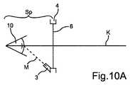
図2に示す眼鏡デバイス1を被検者が着用するとき、図10Aに示す状況が簡単に実現される。アイカメラ3は、被検者の頭部に固定した眼鏡デバイス1により、眼10における少なくとも1つのパラメータを取得する光路Mは、アイカメラ3から眼10に至る直線上に存在する。 When the subject wears the
図3及び図10Bは、眼鏡デバイス1の異なった形態を示す。眼鏡デバイス1は、フレーム4に取付けた光学的転向素子をなすミラー11を有し、ミラー11及びアイカメラ3は、被検者の頭部に固定した眼鏡デバイス1により、眼10における少なくとも1つのパラメータを取得する光路Mが、アイカメラ3からミラー11を経て眼10に至るようフレームに配置する。図3の3次元的表示は、眼鏡デバイス1を後方又は内側から見た状態を示す。この図において、左眼10l及び右眼10rの反射が、それぞれメガネレンズ8l及び8rに見える。座標系は、z軸が投影面に指向するデカルト座標系である。 3 and 10B show different forms of the
このように、アイカメラ3l,3rは、眼10l,10rの前方及び上方に取付け、光ガイド又はミラー11を眼10l,10rの前方及び下方、例えば1対のメガネレンズ8l,8rの下側リム内又は下側リムに配置し、アイカメラ3l,3rが各眼10l,10rの前方及びは下方からの透視画像を取得し、またその画像が眼10l,10rに見えるようにする。光ガイド又はミラー11は、(平坦)ミラー、球面ミラー、ドームミラー、カスタムレンズ、ホログラフィック・イメージガイド等のいずれかとすることができる。ミラー11は、特定波長レンジのみで反射でき、他のレンジに対しては透過性を示すものとすることができる。 As described above, the
ミラー11は平坦ミラー又は球面ミラーのいずれかとすることができる。球面ミラーは、アイカメラ3の視野を平坦ミラーで得られる視野を越えて拡大するという利点がある。図3の形態によれば、さらに、光学系を眼10に極めて(セット方向に)近接させて配置でき、したがって、人間工学的にまた審美的に改善をもたらす。被検者自身の視野はほとんど阻害されない。ミラー11は、いわゆるホットミラーとすることができ、すなわち、このミラーは、可視波長範囲では透過性を示し、赤外線波長レンジでは高い反射性を有する。このミラーは極めて薄くかつ中空(いわゆるドーム状)にすることができ、したがって、屈折に起因するゆがみを減少することができる。それは、極めて低い屈折率(IOR:index of refraction)を示す材料から形成することができる。 The
図10A及び10B双方の場合、アイカメラ3は、眼10における少なくとも1つのパラメータを取得する光路Mがフレームインサート、すなわちメガネレンズ8を除外するよう配置する。さらに、メガネレンズ8は、眼10の光軸K及び光路Mがともに使用する単独の光学的素子として眼10を有するよう配置する。さらに、光路Mは、メガネレンズ8の眼10に対向する側に延びて存在(延在)する空間Sp内に完全に延在する。 10A and 10B, the eye camera 3 is arranged such that the optical path M for obtaining at least one parameter in the
図2及び3並びに図10A及び10Bに示す実施形態それぞれは、ともに上瞼による眼閉じを少なくする。 Each of the embodiments shown in FIGS. 2 and 3 and FIGS. 10A and 10B both reduce eye closure due to upper eyelids.
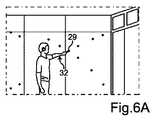
図6A〜8は、従来技術と比較して眼鏡デバイス1のパララックス誤差の減少を示す。図6Aから分かるように、被検者が実際に眼の焦点を合わせている対象物の位置29、及び眼鏡デバイス1が決定した注視ポイント32は、従来既知の眼鏡デバイス1を使用するとき、通常は十分よく一致することはない。この作用は、通常、被検者が眼の焦点を合わせている対象物29に近づけば近づくほど、一層顕著となる。しかし、本発明の実施形態による眼鏡デバイス1では、決定した注視ポイント32と実際の対象物29との間の一致度が極めてよく、測定距離が0.5mの短いものであったとしても、よく一致する(図6B参照)。このことは、眼球中心とカメラの焦点との間の距離を最小化することによって得られる。 6A-8 illustrate the reduction in parallax error of the
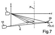
この状況を図7で再び示す。眼10及びシーンカメラ2を僅かに異なった位置に配置するとき、対象物29に合焦するそれぞれの視野角における差は、対象物29が眼10及びシーンカメラ2それぞれに近づけば近づくほど一層顕著となる(すなわち、zの座標値が小さくなればなるほど、より大きいゆがみとなる)。眼鏡デバイス1は図6Bに示す状況に較正することができる。対象物29は較正平面P上に位置し、また眼鏡デバイス1を較正することによって、着用者は、決定された注視ポイント32がまさに実際の対象物29にあると確信できる。較正は、一般的に被検者から若干離れた距離にある平面上で行う。このことは、シーンビデオフレームにおけるピクセルに対する測定した注視方向(角度)に関連する。この計算は、較正平面上に存在するポイントに対してのみ有効な結果を与える。較正平面上にないポイントに対しては、系統的な誤差(パララックス)が入ることになる。対象物29からの眼鏡デバイスの距離が大きくなるとき、較正平面Pまでの距離と対象物29までの実際の距離との差は顕著なずれを生ずる。本発明の実施形態による眼鏡デバイス1では、すべての距離dに対するこれらずれ又はパララックス誤差(図8に円形の記号S2で示す)は、従来技術によるデバイス(矩形の記号S1)によるものよりも相当小さい。細い×印は記号S2のグループに関連し、太い×印は記号S1のグループに関連する。×印は較正目的に使用された注視ポイント32に対応する。 This situation is shown again in FIG. When the
パララックス誤差は、眼の位置に対するシーンカメラ2の位置の関数として数学的にモデル化される。パララックスによる注視推定誤差は、数学的シミュレーションによって示される結果に従って、シーンカメラ2を眼10にできるだけ接近させて配置することにより減少することができる。さらに、パララックス誤差は、両眼追跡から両眼転導を使用して注視ポイントまでの距離を推定することによって、また視線追跡デバイスに対する眼の位置を推定することによって補正することができる。 The parallax error is mathematically modeled as a function of the position of the
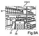
良好な結果を得るため、シーンカメラ2の視野を最適化することができる。標準光学系を有するシーンカメラ2の視野は、生理学上の注視レンジ全体をカバーしない(標準光学系の水平視野:40゜〜50゜; 典型的注視レンジ:60%)。一実施形態において、シーンカメラ2の視野はそれぞれの用途に応じて最適化することができる。このような視野最適化を図9A及び9Bで説明する。眼鏡デバイス1を着用する使用者は、同時に背景B及び携帯電話30を見ている。図9Aによれば、視野FOV(field of view)1は主に背景Bをカバーする。被検者31が携帯電話30に目を落とすとき、注視方向の変化はアイカメラ3l,3r及びシーンカメラ2によって自動的に決定され、視野は風景指向性から人物指向性に切替えることによって自動的に調整される。このことは、シーンカメラ2をz軸周りに90゜機械的に転回(ロール)することにより、又はシーンカメラ2の前面に光学的プリズムを使用することにより行うことができる。さらに、異なるチルト角度又はロール角度を有する2つのシーンカメラを使用することによっても可能である。代案として、光学的ビームスプリッタをシーンカメラ2の前方に使用することができる。 In order to obtain good results, the field of view of the
要するに、眼鏡デバイス1は、3個のカメラ、すなわち、2個のアイカメラ3l,3r及び少なくとも1個のシーンカメラ2よりなるヘッドマウント型視線追跡システムを形成する。3個のカメラ3l,3r及び2は、例えば、調整可能なフレームレート及び解像度によって、管理可能な帯域幅を有することができる。1個又は数個の前処理ユニット6,16,17及び26は、カメラ2,3l,3rから受け取ったビデオストリームの可変圧縮を行うのに設けることができる。ビデオストリームの圧縮レベルは、アイカメラ3l,3r及びシーンカメラ2のものと同一とする、又はアイカメラ3l,3r及びシーンカメラ2のものとは別個のものとすることができる。アイカメラ3lのフレームレートは全速力取得(撮影)に対応し、アイカメラ3rのフレームレートは1/10速力取得に対応し、シーンカメラ2のフレームレートは1/2速力取得に対応するものとすることができる。異なったカメラのフレームレートを調整する代わりに、取得レートを同一となるよう選択し、データ処理をカメラ毎に異ならせて行うようにすることができる。一方のカメラによって得られたデータは、他のカメラによって得られたデータよりも多く圧縮するが、双方のカメラは同一のデータ量を取得するものとすることができる。さらに、異なる圧縮レートと異なる取得レートを組合わせることもできる。さらに、例えば、データを転送するとき、2つ目毎の取得画像を省き、CPUに送るデータ量を半分に減らすこともできる。カメラ2,3l及び3rの信号は、PC27内のCPUに有線又は無線のインタフェース(図5参照)を介して転送することができる。他のデータ源用の補助インタフェース及びこれら他のデータ源との同期方法を眼鏡デバイス1に実装することができる。 In short, the
眼鏡デバイス1は、数個の交換可能なピースよりなるシステムとして構成することができる。眼鏡デバイス1は、小さい鼻又は大きい鼻を有する顔用に、鼻ピース又は鼻支持体7の交換可能なセットを有する。このようにして、眼鏡デバイス1は問題なく視力補正メガネ上に着用することができる。さらに、眼鏡デバイス1は、所定波長レンジ用の異なる透光レベルを有する交換可能なメガネレンズ(例えば、透明メガネ又はサングラス)のための保持機構を有する。付加的に又は代替的に、交換可能なメガネレンズは、近赤外光学的フィルタを有し、照射源の波長にマッチし、また同一及び類似波長の外側から眼の表面に達する光の若干又はすべてをブロックし、眼の表面における信号対ノイズ比を改善できるようにする。眼鏡デバイス1は、アイカメラ3l,3r及びシーンカメラ2のためのマウント又はハウジングとして作用する、リム及び鼻ブリッジを有する。アイカメラ3l,3rは、交換可能なメガネレンズ8l,8rの背後に視野が広がるように取り付ける。 The
眼鏡デバイス1によれば、視線追跡、オキュロメトリクス、バイオメトリクス、及び位置及びモーション測定を行い、自由に動ける設定にした人間行動をできる限り完全に測定及び分類することができるようになる。ヘッドマウント型視線追跡装置は、較正フリーであり、乱視推定を行えるよう実現する。視線追跡機能はセットアップ時間がゼロである。調整は不要である。被検者31は、眼鏡デバイス1を着用するだけで、使用を開始することができる。人の眼の動きにおける生理学的レンジ(水平方向に80゜、垂直方向に60゜)をカバーする極めて大きな注視追跡レンジを有する。眼鏡デバイスは、極めて堅牢であり、注視マッピングに高い精度を有する。眼鏡デバイスは、乱視を補償し、パララックスを少なくし、瞳孔軸線シフトを補償し、また較正フリー若しくは1点較正の特徴を使用して較正を行うことができる。さらに、民族(白色人種、アジア系人種、アフリカ系人種等)、性別及び年齢を問わず動作するよう設計する。シーンカメラ2の視野を最適化する。光学的センサ、慣性センサ又は磁気センサを使用することにより、頭部追跡機能を実装することができる。眼鏡デバイスは、さらに、バイオメトリックの特徴、例えば、瞳孔直径測定、及びEEG、ECG等とのインタフェースをとって同期させる選択肢も与える。最後に、ヘッドマウントディスプレイに組入れることができる。バーチャル画像をパーソナルコンピュータのスクリーンにおける被検眼に投影することができる。さらに、眼の動き(注視、まばたき)を使用してバーチャル画像における「オブジェクト」との対話的相互作用を提供することができる。 According to the
頭部追跡機能は、3軸ジャイロスコープ、3軸加速度計及び/又は3軸磁力計を光学的センサとともに使用し、六次元的頭部追跡用に実現することができる。 The head tracking function can be implemented for six-dimensional head tracking using a 3-axis gyroscope, 3-axis accelerometer and / or 3-axis magnetometer with optical sensors.
要約すると、眼鏡デバイス1は、極めて固有の光学的及び電子的アーキテクチャを用意する。電子的アーキテクチャに関しては、割り当て可能な帯域幅を有する3個以上の高解像度カメラを眼鏡デバイス1に組込む。アイカメラ3l,3r及びシーンカメラ2用の個別の処理チャネルを設けることが考えられる。光学的アーキテクチャは、種々の特性を有する交換可能なメガネレンズによって特徴付けられる。アイカメラ3l,3rの光路は、メガネ又はメガネレンズ8l,8rそれぞれの背後に延在するものとする。さらに、LED9のセットにより、眼10l,10rの極めて可変の照射を行うことができる。例えば、眼の周りの照射ジオメトリを制御することができる。特定LEDのサブセットは、ストロボ効果及び順序付けによって制御することができる。最後に眼の照射は、点光源、ライン光源又は2次元配列光源により行うことができる。 In summary, the
1 眼鏡デバイス
2 シーンカメラ
3,3l,3r アイカメラ
4 フレーム
5l,5r サイドバー
6 前処理ユニット
7 鼻支持体
8,8l,8r メガネレンズ
9 LED
10,10l,10r 眼
11 ミラー
12 マイクロフォン
13 補助/同期ポート
14 ケーブル
15 電子機器
16 前処理ユニット
17 前処理ユニット
18 MPEGエンコーダ
19 USBハブ
20 赤外線LED一定電流源
21,22 赤外線LEDチェーン
23,24 PCB
25 USB2.0ケーブル
26 前処理ユニット
27 パーソナルコンピュータ
28 記録装置
29 対象物
30 携帯電話
31 被検者
32 注視ポイント
w1,w2 幅
h 高さ
l 長さ
a チルト角度
K 光軸
M 光路
O 基準座標系の原点
P 較正平面
Sp 空間
d 距離
S1,S2 記号
B 背景
FOV1,FOV2 視野
x,y,z 軸DESCRIPTION OF
10, 10 l, 10
25 USB 2.0
Claims (14)
Translated fromJapanese前記被検者(31)の頭部に前記光学的測定装置(1)を固定するよう構成したフレーム(4)と、
前記少なくとも一方の眼(10l,10r)における少なくとも1つのパラメータを光学的に捕捉するよう構成した少なくとも1つの捕捉ユニット(3l,3r)と、
前記少なくとも一方の眼(10l,10r)に可視光又は赤外光を照射する照射ユニット(9,21,22)とを備えた、該光学的測定装置において、
前記照射ユニット(9,21,22)により照射特性を調整可能にし、前記照射特性は、前記少なくとも1つの捕捉ユニットの認識パターンとして作用し、前記少なくとも1つの補足ユニットは、前記照射特性を捕捉して識別するように構成された、ことを特徴とする光学的測定装置。An optical measurement device (1) for capturing at least one parameter in at least one eye (101, 10r) of a subject (31) wearing the optical measurement device (1),
A frame (4) configured to fix the optical measuring device (1) to the head of the subject (31);
At least one capture unit (3l, 3r) configured to optically capture at least one parameter in said at least one eye (10l, 10r);
In the optical measurement apparatus comprising: an irradiation unit (9, 21, 22) that irradiates visible light or infrared light to the at least one eye (10l, 10r);
The irradiation characteristic can be adjusted by the irradiation unit (9, 21, 22), the irradiation characteristic acts as a recognition pattern of the at least one capture unit, and the at least one supplementary unit captures the irradiation characteristic. An optical measuring device, characterized in that the optical measuring device is configured to be identified.
前記フレーム(4)は、メガネレンズ(8l,8r)を収容する少なくとも1個のフレーム素子を有し、前記光学的測定装置(1)を被検者(31)の頭部に固定した状態で、前記フレーム素子が枠付けする部分が前記被検者(31)の前記少なくとも一方の眼(10l,10r)の前方に位置し、
前記照射ユニット(9,21,22)は、前記フレーム素子上又は前記フレーム素子の範囲内に配置された、ことを特徴とする光学的測定装置。In the optical measuring device (1) according to any one of claims 1 to 7,
The frame (4) has at least one frame element that accommodates the eyeglass lenses (81, 8r), and the optical measuring device (1) is fixed to the head of the subject (31). The portion of the frame element to be framed is located in front of the at least one eye (10l, 10r) of the subject (31);
The optical measurement apparatus, wherein the irradiation unit (9, 21, 22) is arranged on the frame element or in the range of the frame element.
・前記被検者(31)の頭部に光学的測定装置(1)を固定する固定ステップであり、前記光学的測定装置(1)は、少なくとも1個の捕捉ユニット(3l,3r)及び照射ユニット(9,21,22)を備えたものとする、該固定ステップと、
・前記照射ユニット(9,21,22)により前記少なくとも一方の眼(10l,10r)に可視光又は赤外光を照射するステップと、
・前記少なくとも一方の眼(10l,10r)における少なくとも1つのパラメータを前記捕捉ユニット(3l,3r)によって光学的に捕捉するステップと
を含む、該方法において、さらに、以下のステップ、すなわち、
・照射特性を設定するステップと、
・前記設定した照射特性に従って前記照射ユニット(9,21,22)により前記少なくとも一方の眼(10l,10r)に可視光又は赤外光を照射するステップであって、前記照射特性は、前記少なくとも1つの捕捉ユニットの認識パターンとして作用し、前記少なくとも1つの補足ユニットは、前記照射特性を捕捉して識別する、ことを特徴とする方法。A method for capturing at least one parameter in at least one eye (10l, 10r) of a subject (31) comprising the following steps:
A fixing step of fixing the optical measurement device (1) to the head of the subject (31), the optical measurement device (1) comprising at least one capture unit (3l, 3r) and irradiation; The fixing step comprising a unit (9, 21, 22);
Irradiating the at least one eye (101, 10r) with visible light or infrared light by the irradiation unit (9, 21, 22);
Optically capturing at least one parameter in the at least one eye (101, 10r) by the capturing unit (31, 3r), further comprising the following steps:
A step for setting the irradiation characteristics;
Irradiating the at least one eye (10l, 10r) with visible light or infrared light by the irradiation unit (9, 21, 22) according to the set irradiation characteristic, the irradiation characteristic being at least Acting as a recognition pattern for one capture unit, wherein the at least one supplemental unit captures and identifies the illumination characteristic.
・前記少なくとも一方の眼(10l,10r)における少なくとも2つの光反射及び/又は特徴を光学的に捕捉するステップと、
・前記捕捉した光反射及び/又は特徴によって前記少なくとも一方の眼(10l,10r)における少なくとも1つのパラメータを決定するステップと
を含む、ことを特徴とする方法。12. The method according to claim 10 or 11, wherein the step of optically capturing at least one parameter in the at least one eye (10l, 10r) comprises the following sub-steps:
Optically capturing at least two light reflections and / or features in the at least one eye (101, 10r);
Determining at least one parameter in the at least one eye (10l, 10r) according to the captured light reflection and / or characteristics.
・前記被検者(31)の視認挙動及び/又は眼の動き特性及び/又は瞳孔変化及び/又は外部条件及び/又は前記被検者(31)の入力に関するデータを取得するステップと、
・前記取得したデータに応じて、前記時間的及び/若しくは空間的照射分布、並びに/又は照射パターンのための照射プログラムを設定するステップと
・前記設定した照射プログラムに従って前記時間的照射シーケンス及び/又は空間的照射分布及び/又は照射パターンを調節するステップと
を含む、ことを特徴とする方法。
In claim 11 Symbol mounting method, the following steps, namely,
Obtaining data relating to the visual behavior and / or eye movement characteristics and / or pupil changes and / or external conditions of the subject (31) and / or input of the subject (31);
Setting the irradiation program for the temporal and / or spatial irradiation distribution and / or irradiation pattern according to the acquired data; and the temporal irradiation sequence and / or according to the set irradiation program. Adjusting the spatial illumination distribution and / or illumination pattern.
Applications Claiming Priority (5)
| Application Number | Priority Date | Filing Date | Title |
|---|---|---|---|
| EP11158891 | 2011-03-18 | ||
| EP11158891.9 | 2011-03-18 | ||
| EP11173753.2AEP2499962B1 (en) | 2011-03-18 | 2011-07-13 | Optical measuring device and method for capturing at least one parameter of at least one eye wherein an illumination characteristic is adjustable |
| EP11173753.2 | 2011-07-13 | ||
| PCT/EP2012/054609WO2012126810A1 (en) | 2011-03-18 | 2012-03-15 | Optical measuring device and method for capturing at least one parameter of at least one eye wherein an illumination characteristic is adjustable |
Publications (2)
| Publication Number | Publication Date |
|---|---|
| JP2014509533A JP2014509533A (en) | 2014-04-21 |
| JP6159263B2true JP6159263B2 (en) | 2017-07-05 |
Family
ID=45607837
Family Applications (4)
| Application Number | Title | Priority Date | Filing Date |
|---|---|---|---|
| JP2013558450AActiveJP6159263B2 (en) | 2011-03-18 | 2012-03-15 | Optical measurement apparatus and method for adjusting illumination characteristics and capturing at least one parameter in at least one eye |
| JP2013558451AActiveJP6159264B2 (en) | 2011-03-18 | 2012-03-15 | Eyeglass device and method with adjustable field of view |
| JP2013558448AActiveJP6026444B2 (en) | 2011-03-18 | 2012-03-15 | Method and optical measuring device for determining at least one parameter in two eyes by setting a data transfer rate |
| JP2013558449AActiveJP6030075B2 (en) | 2011-03-18 | 2012-03-15 | Optical measuring apparatus and system |
Family Applications After (3)
| Application Number | Title | Priority Date | Filing Date |
|---|---|---|---|
| JP2013558451AActiveJP6159264B2 (en) | 2011-03-18 | 2012-03-15 | Eyeglass device and method with adjustable field of view |
| JP2013558448AActiveJP6026444B2 (en) | 2011-03-18 | 2012-03-15 | Method and optical measuring device for determining at least one parameter in two eyes by setting a data transfer rate |
| JP2013558449AActiveJP6030075B2 (en) | 2011-03-18 | 2012-03-15 | Optical measuring apparatus and system |
Country Status (5)
| Country | Link |
|---|---|
| US (5) | US20140078283A1 (en) |
| EP (5) | EP2499964B1 (en) |
| JP (4) | JP6159263B2 (en) |
| CN (3) | CN103442629B (en) |
| WO (4) | WO2012126809A1 (en) |
Families Citing this family (193)
| Publication number | Priority date | Publication date | Assignee | Title |
|---|---|---|---|---|
| US9952664B2 (en) | 2014-01-21 | 2018-04-24 | Osterhout Group, Inc. | Eye imaging in head worn computing |
| US9715112B2 (en) | 2014-01-21 | 2017-07-25 | Osterhout Group, Inc. | Suppression of stray light in head worn computing |
| US9298007B2 (en) | 2014-01-21 | 2016-03-29 | Osterhout Group, Inc. | Eye imaging in head worn computing |
| US9229233B2 (en) | 2014-02-11 | 2016-01-05 | Osterhout Group, Inc. | Micro Doppler presentations in head worn computing |
| US9400390B2 (en) | 2014-01-24 | 2016-07-26 | Osterhout Group, Inc. | Peripheral lighting for head worn computing |
| US9965681B2 (en) | 2008-12-16 | 2018-05-08 | Osterhout Group, Inc. | Eye imaging in head worn computing |
| IL221863A (en)* | 2012-09-10 | 2014-01-30 | Elbit Systems Ltd | Digital system for surgical video capturing and display |
| US9894269B2 (en) | 2012-10-31 | 2018-02-13 | Atheer, Inc. | Method and apparatus for background subtraction using focus differences |
| JP6066676B2 (en)* | 2012-11-06 | 2017-01-25 | 株式会社ソニー・インタラクティブエンタテインメント | Head mounted display and video presentation system |
| CN102961119B (en)* | 2012-11-26 | 2015-01-07 | 深圳恒兴视光科技有限公司 | Centrometer |
| KR102205374B1 (en) | 2012-12-06 | 2021-01-21 | 아이플루언스, 인크. | Eye tracking wearable devices and methods for use |
| US20140176327A1 (en)* | 2012-12-20 | 2014-06-26 | Nokia Corporation | Method and apparatus for determining that medical assistance may be required |
| US9160915B1 (en)* | 2013-01-09 | 2015-10-13 | Amazon Technologies, Inc. | Modifying device functionality based on device orientation |
| GB2513579A (en)* | 2013-04-29 | 2014-11-05 | Tobii Technology Ab | Power efficient image sensing apparatus, method of operating the same and eye/gaze tracking system |
| JP6330258B2 (en)* | 2013-05-15 | 2018-05-30 | セイコーエプソン株式会社 | Virtual image display device |
| TWI505260B (en)* | 2013-07-30 | 2015-10-21 | Univ Nat Chiao Tung | Head-mount eye tracking system |
| AT513987B1 (en)* | 2013-08-23 | 2014-09-15 | Ernst Dipl Ing Dr Pfleger | Spectacles and methods for determining pupil centers of both eyes of a human |
| US10686972B2 (en) | 2013-09-03 | 2020-06-16 | Tobii Ab | Gaze assisted field of view control |
| CN113576398A (en)* | 2013-09-03 | 2021-11-02 | 托比股份公司 | Portable eye tracking device |
| US11327302B2 (en) | 2013-09-18 | 2022-05-10 | Beth Holst | Secure capture and transfer of image and audio data |
| US10008124B1 (en) | 2013-09-18 | 2018-06-26 | Beth Holst | Method and system for providing secure remote testing |
| US9332903B2 (en) | 2013-09-19 | 2016-05-10 | Gn Otometrics A/S | Headgear for observation of eye movements |
| JP2015061595A (en)* | 2013-09-19 | 2015-04-02 | ジーエヌ オトメトリックス エー/エスGN Otometrics A/S | Headgear for observation of eye movements |
| US9785231B1 (en)* | 2013-09-26 | 2017-10-10 | Rockwell Collins, Inc. | Head worn display integrity monitor system and methods |
| CN104706422A (en)* | 2013-12-13 | 2015-06-17 | Ge医疗系统环球技术有限公司 | Head-worn type medical device, medical system and operation method of medical system |
| US9575321B2 (en) | 2014-06-09 | 2017-02-21 | Osterhout Group, Inc. | Content presentation in head worn computing |
| US9810906B2 (en) | 2014-06-17 | 2017-11-07 | Osterhout Group, Inc. | External user interface for head worn computing |
| US10684687B2 (en) | 2014-12-03 | 2020-06-16 | Mentor Acquisition One, Llc | See-through computer display systems |
| US11103122B2 (en) | 2014-07-15 | 2021-08-31 | Mentor Acquisition One, Llc | Content presentation in head worn computing |
| US9939934B2 (en) | 2014-01-17 | 2018-04-10 | Osterhout Group, Inc. | External user interface for head worn computing |
| US9594246B2 (en) | 2014-01-21 | 2017-03-14 | Osterhout Group, Inc. | See-through computer display systems |
| US9299194B2 (en) | 2014-02-14 | 2016-03-29 | Osterhout Group, Inc. | Secure sharing in head worn computing |
| US9841599B2 (en) | 2014-06-05 | 2017-12-12 | Osterhout Group, Inc. | Optical configurations for head-worn see-through displays |
| US9746686B2 (en) | 2014-05-19 | 2017-08-29 | Osterhout Group, Inc. | Content position calibration in head worn computing |
| US20160019715A1 (en) | 2014-07-15 | 2016-01-21 | Osterhout Group, Inc. | Content presentation in head worn computing |
| US10254856B2 (en) | 2014-01-17 | 2019-04-09 | Osterhout Group, Inc. | External user interface for head worn computing |
| US9529195B2 (en) | 2014-01-21 | 2016-12-27 | Osterhout Group, Inc. | See-through computer display systems |
| US11227294B2 (en) | 2014-04-03 | 2022-01-18 | Mentor Acquisition One, Llc | Sight information collection in head worn computing |
| US10649220B2 (en) | 2014-06-09 | 2020-05-12 | Mentor Acquisition One, Llc | Content presentation in head worn computing |
| US20150277118A1 (en) | 2014-03-28 | 2015-10-01 | Osterhout Group, Inc. | Sensor dependent content position in head worn computing |
| US9671613B2 (en) | 2014-09-26 | 2017-06-06 | Osterhout Group, Inc. | See-through computer display systems |
| US10191279B2 (en) | 2014-03-17 | 2019-01-29 | Osterhout Group, Inc. | Eye imaging in head worn computing |
| US9829707B2 (en) | 2014-08-12 | 2017-11-28 | Osterhout Group, Inc. | Measuring content brightness in head worn computing |
| US9766463B2 (en) | 2014-01-21 | 2017-09-19 | Osterhout Group, Inc. | See-through computer display systems |
| US9494800B2 (en) | 2014-01-21 | 2016-11-15 | Osterhout Group, Inc. | See-through computer display systems |
| US20150205135A1 (en) | 2014-01-21 | 2015-07-23 | Osterhout Group, Inc. | See-through computer display systems |
| US12105281B2 (en) | 2014-01-21 | 2024-10-01 | Mentor Acquisition One, Llc | See-through computer display systems |
| US11487110B2 (en) | 2014-01-21 | 2022-11-01 | Mentor Acquisition One, Llc | Eye imaging in head worn computing |
| US12093453B2 (en) | 2014-01-21 | 2024-09-17 | Mentor Acquisition One, Llc | Eye glint imaging in see-through computer display systems |
| US9753288B2 (en) | 2014-01-21 | 2017-09-05 | Osterhout Group, Inc. | See-through computer display systems |
| US9740280B2 (en) | 2014-01-21 | 2017-08-22 | Osterhout Group, Inc. | Eye imaging in head worn computing |
| US11669163B2 (en) | 2014-01-21 | 2023-06-06 | Mentor Acquisition One, Llc | Eye glint imaging in see-through computer display systems |
| US9615742B2 (en) | 2014-01-21 | 2017-04-11 | Osterhout Group, Inc. | Eye imaging in head worn computing |
| US9651788B2 (en) | 2014-01-21 | 2017-05-16 | Osterhout Group, Inc. | See-through computer display systems |
| US11892644B2 (en) | 2014-01-21 | 2024-02-06 | Mentor Acquisition One, Llc | See-through computer display systems |
| US9836122B2 (en) | 2014-01-21 | 2017-12-05 | Osterhout Group, Inc. | Eye glint imaging in see-through computer display systems |
| US11737666B2 (en) | 2014-01-21 | 2023-08-29 | Mentor Acquisition One, Llc | Eye imaging in head worn computing |
| US9651784B2 (en) | 2014-01-21 | 2017-05-16 | Osterhout Group, Inc. | See-through computer display systems |
| US9811152B2 (en) | 2014-01-21 | 2017-11-07 | Osterhout Group, Inc. | Eye imaging in head worn computing |
| US9846308B2 (en) | 2014-01-24 | 2017-12-19 | Osterhout Group, Inc. | Haptic systems for head-worn computers |
| US9794475B1 (en) | 2014-01-29 | 2017-10-17 | Google Inc. | Augmented video capture |
| US20170090557A1 (en)* | 2014-01-29 | 2017-03-30 | Google Inc. | Systems and Devices for Implementing a Side-Mounted Optical Sensor |
| US9401540B2 (en) | 2014-02-11 | 2016-07-26 | Osterhout Group, Inc. | Spatial location presentation in head worn computing |
| US20170017481A1 (en)* | 2014-02-12 | 2017-01-19 | Nokia Technologies Oy | Method and apparatus for updating a firmware of an apparatus |
| GB2523356A (en)* | 2014-02-21 | 2015-08-26 | Tobii Technology Ab | Apparatus and method for robust eye/gaze tracking |
| US10430985B2 (en)* | 2014-03-14 | 2019-10-01 | Magic Leap, Inc. | Augmented reality systems and methods utilizing reflections |
| US20160187651A1 (en) | 2014-03-28 | 2016-06-30 | Osterhout Group, Inc. | Safety for a vehicle operator with an hmd |
| US9361519B2 (en)* | 2014-03-28 | 2016-06-07 | Intel Corporation | Computational array camera with dynamic illumination for eye tracking |
| JP2015202183A (en)* | 2014-04-14 | 2015-11-16 | 株式会社ジェイアイエヌ | Detection control device, attachment tool, eye potential information processing system, and program |
| JP2015202199A (en)* | 2014-04-14 | 2015-11-16 | 株式会社ジェイアイエヌ | Electrooculogram information processing apparatus, electrooculogram information processing system, wearing tool and program |
| US10853589B2 (en) | 2014-04-25 | 2020-12-01 | Mentor Acquisition One, Llc | Language translation with head-worn computing |
| US9651787B2 (en) | 2014-04-25 | 2017-05-16 | Osterhout Group, Inc. | Speaker assembly for headworn computer |
| US9672210B2 (en) | 2014-04-25 | 2017-06-06 | Osterhout Group, Inc. | Language translation with head-worn computing |
| WO2016018487A2 (en)* | 2014-05-09 | 2016-02-04 | Eyefluene, Inc. | Systems and methods for biomechanically-based eye signals for interacting with real and virtual objects |
| US10663740B2 (en) | 2014-06-09 | 2020-05-26 | Mentor Acquisition One, Llc | Content presentation in head worn computing |
| CN106937531B (en)* | 2014-06-14 | 2020-11-06 | 奇跃公司 | Method and system for generating virtual and augmented reality |
| CN104111530A (en) | 2014-06-30 | 2014-10-22 | 联想(北京)有限公司 | Information processing method and wearable electronic equipment |
| US10540907B2 (en) | 2014-07-31 | 2020-01-21 | Intelligent Technologies International, Inc. | Biometric identification headpiece system for test taking |
| US9465991B2 (en) | 2014-08-11 | 2016-10-11 | Microsoft Technology Licensing, Llc | Determining lens characteristics |
| EP3182881B1 (en)* | 2014-08-20 | 2023-11-29 | California Baptist University | Systems for monitoring eye health |
| US10410535B2 (en) | 2014-08-22 | 2019-09-10 | Intelligent Technologies International, Inc. | Secure testing device |
| CN106662746B (en) | 2014-08-22 | 2020-10-23 | 国际智能技术公司 | Secure examination device, system and method |
| AT516326B1 (en)* | 2014-09-29 | 2016-07-15 | Pocket Sky Og | Device for signal transmission to the eye |
| WO2016073202A1 (en) | 2014-11-04 | 2016-05-12 | Intelligent Technologies International, Inc. | Smartcard |
| US9804392B2 (en) | 2014-11-20 | 2017-10-31 | Atheer, Inc. | Method and apparatus for delivering and controlling multi-feed data |
| EP3023827A1 (en)* | 2014-11-20 | 2016-05-25 | GN Otometrics A/S | Head mountable device for measuring eye movement having visible projection means |
| US9684172B2 (en) | 2014-12-03 | 2017-06-20 | Osterhout Group, Inc. | Head worn computer display systems |
| USD751552S1 (en) | 2014-12-31 | 2016-03-15 | Osterhout Group, Inc. | Computer glasses |
| USD753114S1 (en) | 2015-01-05 | 2016-04-05 | Osterhout Group, Inc. | Air mouse |
| US10567641B1 (en)* | 2015-01-19 | 2020-02-18 | Devon Rueckner | Gaze-directed photography |
| US20160239985A1 (en) | 2015-02-17 | 2016-08-18 | Osterhout Group, Inc. | See-through computer display systems |
| NZ773836A (en) | 2015-03-16 | 2022-07-01 | Magic Leap Inc | Methods and systems for diagnosing and treating health ailments |
| EP3305190A4 (en) | 2015-06-01 | 2018-12-26 | Alps Electric Co., Ltd. | Glasses-type electronic device |
| US9870049B2 (en)* | 2015-07-31 | 2018-01-16 | Google Llc | Reflective lenses to auto-calibrate a wearable system |
| US20200081524A1 (en)* | 2015-08-07 | 2020-03-12 | Apple Inc. | Method and appartus for data capture and evaluation of ambient data |
| JP2016127587A (en)* | 2015-09-03 | 2016-07-11 | 株式会社Fove | Head-mounted display |
| WO2017042612A1 (en)* | 2015-09-12 | 2017-03-16 | Shamir Optical Industry Ltd. | Automatic eyewear measurement and specification |
| US11109916B2 (en) | 2015-11-09 | 2021-09-07 | Digital Surgicals Pte Ltd | Personalized hand-eye coordinated digital stereo microscopic systems and methods |
| US10043075B2 (en)* | 2015-11-19 | 2018-08-07 | Microsoft Technology Licensing, Llc | Eye feature identification |
| US10241569B2 (en) | 2015-12-08 | 2019-03-26 | Facebook Technologies, Llc | Focus adjustment method for a virtual reality headset |
| US10445860B2 (en) | 2015-12-08 | 2019-10-15 | Facebook Technologies, Llc | Autofocus virtual reality headset |
| US10963063B2 (en)* | 2015-12-18 | 2021-03-30 | Sony Corporation | Information processing apparatus, information processing method, and program |
| US10678958B2 (en) | 2015-12-28 | 2020-06-09 | Intelligent Technologies International, Inc. | Intrusion-protected memory component |
| IL260604B2 (en)* | 2016-01-19 | 2023-09-01 | Magic Leap Inc | Augmented reality systems and methods utilizing reflections |
| WO2017127494A1 (en)* | 2016-01-22 | 2017-07-27 | Corning Incorporated | Wide field personal display |
| US11054648B2 (en)* | 2016-02-04 | 2021-07-06 | Google Llc | Compact near-eye display optics for higher optical performance |
| USD794112S1 (en)* | 2016-03-07 | 2017-08-08 | Snap Inc. | Eyeglasses |
| JP2017163180A (en)* | 2016-03-07 | 2017-09-14 | 富士通株式会社 | Deviation determination program, deviation determination method, and information processing apparatus |
| US11106276B2 (en) | 2016-03-11 | 2021-08-31 | Facebook Technologies, Llc | Focus adjusting headset |
| US10379356B2 (en) | 2016-04-07 | 2019-08-13 | Facebook Technologies, Llc | Accommodation based optical correction |
| JP6923552B2 (en) | 2016-04-08 | 2021-08-18 | マジック リープ, インコーポレイテッドMagic Leap,Inc. | Augmented reality systems and methods with varifocal lens elements |
| CN105676458A (en)* | 2016-04-12 | 2016-06-15 | 王鹏 | Wearable calculation device and control method thereof, and wearable equipment with wearable calculation device |
| KR102522502B1 (en) | 2016-04-26 | 2023-04-17 | 매직 립, 인코포레이티드 | Electromagnetic tracking with augmented reality systems |
| EP3448229A4 (en)* | 2016-04-28 | 2019-12-04 | Alex Artsyukhovich | DETACHABLE MINIATURE MICROSCOPE MOUNTED KERATOMETER FOR CATARACT SURGERY |
| US9854968B2 (en)* | 2016-05-20 | 2018-01-02 | International Business Machines Corporation | Behind-eye monitoring using natural reflection of lenses |
| US10684479B2 (en)* | 2016-06-15 | 2020-06-16 | Vrvaorigin Vision Technology Corp. Ltd. | Head-mounted personal multimedia systems and visual assistance devices thereof |
| EP3751396A1 (en)* | 2016-06-16 | 2020-12-16 | Apple Inc. | Method and system for providing eye tracking based information about a user behavior, client device, server and computer program product |
| CN106200901B (en)* | 2016-06-24 | 2019-03-29 | 联想(北京)有限公司 | A kind of bearing calibration of wear-type ocular pursuit device and wear-type ocular pursuit device |
| KR102669685B1 (en) | 2016-07-25 | 2024-05-29 | 매직 립, 인코포레이티드 | Light field processor system |
| CN106293100A (en)* | 2016-08-24 | 2017-01-04 | 上海与德通讯技术有限公司 | The determination method of sight line focus and virtual reality device in virtual reality device |
| US10828560B2 (en)* | 2016-09-30 | 2020-11-10 | Sony Interactive Entertainment Inc. | Systems and methods for stereoscopic vision with head mounted display |
| EP3306528B1 (en)* | 2016-10-04 | 2019-12-25 | Axis AB | Using image analysis algorithms for providing traning data to neural networks |
| US10877556B2 (en)* | 2016-10-21 | 2020-12-29 | Apple Inc. | Eye tracking system |
| CN107066079A (en) | 2016-11-29 | 2017-08-18 | 阿里巴巴集团控股有限公司 | Service implementation method and device based on virtual reality scenario |
| CN206301289U (en)* | 2016-11-29 | 2017-07-04 | 阿里巴巴集团控股有限公司 | VR terminal equipment |
| US9905143B1 (en)* | 2016-12-01 | 2018-02-27 | Varjo Technologies Oy | Display apparatus and method of displaying using image renderers and optical combiners |
| WO2018129034A1 (en)* | 2017-01-04 | 2018-07-12 | 3M Innovative Properties Company | Asymmetric turning film with top-hat light output distributions |
| US10310598B2 (en)* | 2017-01-17 | 2019-06-04 | Facebook Technologies, Llc | Varifocal head-mounted display including modular air spaced optical assembly |
| IL311431A (en) | 2017-02-23 | 2024-05-01 | Magic Leap Inc | Display system with variable power reflector |
| US10545347B2 (en) | 2017-02-23 | 2020-01-28 | Google Llc | Compact eye tracking using folded display optics |
| CN106873158A (en)* | 2017-02-27 | 2017-06-20 | 阿里巴巴集团控股有限公司 | Virtual reality helmet |
| CN106873159A (en) | 2017-02-27 | 2017-06-20 | 阿里巴巴集团控股有限公司 | Virtual reality helmet |
| CN107122642A (en) | 2017-03-15 | 2017-09-01 | 阿里巴巴集团控股有限公司 | Identity identifying method and device based on reality environment |
| JP6941952B2 (en)* | 2017-03-28 | 2021-09-29 | 株式会社トプコン | Ophthalmic equipment |
| IL269861B2 (en)* | 2017-04-14 | 2023-11-01 | Magic Leap Inc | Multimodal eye tracking |
| US10976551B2 (en) | 2017-08-30 | 2021-04-13 | Corning Incorporated | Wide field personal display device |
| US10379628B2 (en)* | 2017-09-27 | 2019-08-13 | Htc Corporation | Tracking system, virtual reality system and attachable device |
| FI20175960A1 (en) | 2017-10-30 | 2019-05-01 | Univ Of Eastern Finland | Method and apparatus for gaze detection |
| US11138301B1 (en)* | 2017-11-20 | 2021-10-05 | Snap Inc. | Eye scanner for user identification and security in an eyewear device |
| US10728517B2 (en)* | 2017-12-22 | 2020-07-28 | Flir Systems Ab | Parallax mitigation for multi-imager systems and methods |
| JP7020110B2 (en)* | 2017-12-26 | 2022-02-16 | トヨタ自動車株式会社 | Manufacturing method of catalyst for exhaust gas purification and catalyst for exhaust gas purification |
| JP2019124772A (en)* | 2018-01-15 | 2019-07-25 | 株式会社東海理化電機製作所 | Imaging device |
| CN108089326B (en)* | 2018-02-01 | 2023-12-26 | 北京七鑫易维信息技术有限公司 | Device suitable for being used with glasses |
| EP3750028B1 (en) | 2018-02-09 | 2022-10-19 | Pupil Labs GmbH | Devices, systems and methods for predicting gaze-related parameters |
| WO2019154511A1 (en) | 2018-02-09 | 2019-08-15 | Pupil Labs Gmbh | Devices, systems and methods for predicting gaze-related parameters using a neural network |
| US11393251B2 (en) | 2018-02-09 | 2022-07-19 | Pupil Labs Gmbh | Devices, systems and methods for predicting gaze-related parameters |
| US10845872B2 (en) | 2018-02-09 | 2020-11-24 | Ricoh Company, Ltd. | Eye-gaze tracker, eye-gaze tracking method, and recording medium |
| KR102579034B1 (en)* | 2018-02-23 | 2023-09-15 | 삼성전자주식회사 | An electronic device including a semi-transparent member disposed at an angle specified with respect to a direction in which a video is outputbelow the video outputmodule |
| FR3079936B1 (en)* | 2018-04-04 | 2020-04-17 | Institut Mines-Telecom | OPTICAL SYSTEM FOR DETECTING AND TRACKING EYE MOVEMENTS, EXTERNAL MOUNT AND CONNECTED CONTACT LENS THEREOF |
| CN110596889A (en)* | 2018-06-13 | 2019-12-20 | 托比股份公司 | Eye tracking device and method of manufacturing an eye tracking device |
| EP3826528A4 (en)* | 2018-07-25 | 2022-07-27 | Natus Medical Incorporated | Real-time removal of ir led reflections from an image |
| JP7227989B2 (en)* | 2018-08-21 | 2023-02-22 | メタ プラットフォームズ テクノロジーズ, リミテッド ライアビリティ カンパニー | Illumination assembly with in-field microdevices |
| US10809760B1 (en)* | 2018-10-29 | 2020-10-20 | Facebook, Inc. | Headset clock synchronization |
| US11500185B2 (en)* | 2018-11-09 | 2022-11-15 | Meta Platforms Technologies, Llc | Catadioptric and refractive optical structures for beam shaping |
| US20200150425A1 (en)* | 2018-11-09 | 2020-05-14 | Facebook Technologies, Llc | Inconspicuous near-eye electrical components |
| US10914945B2 (en) | 2018-11-09 | 2021-02-09 | Facebook Technologies, Llc | Inconspicuous near-eye electrical circuits |
| CN109725714B (en) | 2018-11-14 | 2022-06-14 | 北京七鑫易维信息技术有限公司 | Sight line determining method, device and system and head-mounted eye movement equipment |
| EP3891696A1 (en) | 2018-12-04 | 2021-10-13 | Telefonaktiebolaget Lm Ericsson (Publ) | Improved optical see-through viewing device and method for providing virtual content overlapping visual objects |
| USD879868S1 (en)* | 2018-12-27 | 2020-03-31 | Snap Inc. | Eyewear |
| USD879865S1 (en)* | 2018-12-27 | 2020-03-31 | Snap Inc. | Eyewear |
| US11537202B2 (en) | 2019-01-16 | 2022-12-27 | Pupil Labs Gmbh | Methods for generating calibration data for head-wearable devices and eye tracking system |
| US11861063B2 (en) | 2019-02-05 | 2024-01-02 | Samsung Electronics Co., Ltd. | Eye-tracking device and display apparatus including the same |
| US10764571B1 (en)* | 2019-04-22 | 2020-09-01 | Snap Inc. | Camera holder for economical and simplified test alignment |
| US11786694B2 (en) | 2019-05-24 | 2023-10-17 | NeuroLight, Inc. | Device, method, and app for facilitating sleep |
| EP3979896B1 (en) | 2019-06-05 | 2024-11-13 | Pupil Labs GmbH | Devices, systems and methods for predicting gaze-related parameters |
| WO2020244780A1 (en)* | 2019-06-07 | 2020-12-10 | Telefonaktiebolaget Lm Ericsson (Publ) | Improved optical see-through viewing device and method for calibrating provision of virtual content overlapping visual objects |
| WO2020253949A1 (en) | 2019-06-18 | 2020-12-24 | Pupil Labs Gmbh | Systems and methods for determining one or more parameters of a user's eye |
| CN110441901A (en)* | 2019-08-14 | 2019-11-12 | 东北大学 | It is a kind of can real-time tracing watch the optical microscope system and method for position attentively |
| CN111651034B (en)* | 2019-12-05 | 2023-12-26 | 寰采星科技(宁波)有限公司 | Intelligent glasses, control method and control chip of intelligent glasses |
| EP3973346B1 (en) | 2020-02-19 | 2024-12-25 | Pupil Labs GmbH | Eye tracking module and head-wearable device |
| AT523152B1 (en)* | 2020-02-24 | 2021-06-15 | Univ Graz Tech | Device for detecting eye movements |
| US12007810B2 (en)* | 2020-04-23 | 2024-06-11 | Apple Inc. | Electronic devices with antennas and optical components |
| EP3935433B1 (en)* | 2020-05-14 | 2022-05-04 | Viewpoint Sicherheitsforschung - Blickforschung GmbH | Spectacles and method for determining the pupil center |
| CN111783660B (en)* | 2020-07-01 | 2023-11-10 | 业成科技(成都)有限公司 | Eye movement tracking device and electronic device using same |
| IL299948A (en) | 2020-07-23 | 2023-03-01 | Magic Leap Inc | Eye tracking using alternate sampling |
| CN112244763A (en)* | 2020-10-20 | 2021-01-22 | 垒途智能教科技术研究院江苏有限公司 | Head-wearing glasses type eye movement instrument convenient to adjust |
| CN116635769A (en)* | 2021-01-18 | 2023-08-22 | 三星电子株式会社 | Wearable electronic device including miniature camera |
| EP4387519A4 (en)* | 2021-08-18 | 2025-08-06 | Advanced Neuromodulation Systems Inc | SYSTEMS AND METHODS FOR PROVIDING DIGITAL HEALTH SERVICES |
| WO2023146876A1 (en) | 2022-01-26 | 2023-08-03 | Apple Inc. | Eye tracking using efficient image capture and vergence and inter-pupillary distance history |
| US11818472B2 (en) | 2022-01-31 | 2023-11-14 | Donald Siu | Simultaneously capturing images in landscape and portrait modes |
| WO2023203923A1 (en)* | 2022-04-22 | 2023-10-26 | ソニーグループ株式会社 | Head-mounted information processing device, information processing method, recording medium |
| US11806078B1 (en) | 2022-05-01 | 2023-11-07 | Globe Biomedical, Inc. | Tear meniscus detection and evaluation system |
| CN117055209A (en)* | 2022-05-07 | 2023-11-14 | 北京七鑫易维信息技术有限公司 | Eye movement tracking device |
| US12032737B2 (en)* | 2022-08-22 | 2024-07-09 | Meta Platforms Technologies, Llc | Gaze adjusted avatars for immersive reality applications |
| CN117812452A (en)* | 2022-09-22 | 2024-04-02 | 北京字跳网络技术有限公司 | Eye image acquisition method, device, equipment and medium |
| CN115624315B (en)* | 2022-11-18 | 2023-03-14 | 北京中科睿医信息科技有限公司 | Eye movement tracking method and device, electronic equipment, computer storage medium and product |
| JP2024092340A (en) | 2022-12-26 | 2024-07-08 | キヤノン株式会社 | Eye gaze detection device |
| US12339457B2 (en) | 2022-12-26 | 2025-06-24 | Canon Kabushiki Kaisha | Line-of-sight detection device and head mounted display device |
| US12186019B2 (en) | 2023-04-07 | 2025-01-07 | Globe Biomedical, Inc | Mechanical integration of components of wearable devices and ocular health monitoring system |
| USD1058631S1 (en) | 2023-04-07 | 2025-01-21 | Globe Biomedical, Inc. | Smart spectacles |
| USD1057791S1 (en) | 2023-04-07 | 2025-01-14 | Globe Biomedical, Inc. | Smart spectacles |
| CN116645787A (en)* | 2023-05-04 | 2023-08-25 | 浙江极氪智能科技有限公司 | AR device for assisting safe driving and method for assisting safe driving |
| DE102023209501A1 (en)* | 2023-09-28 | 2025-04-03 | Robert Bosch Gesellschaft mit beschränkter Haftung | Method for calibrating data glasses having a virtual retinal display, computing unit and data glasses |
Family Cites Families (72)
| Publication number | Priority date | Publication date | Assignee | Title |
|---|---|---|---|---|
| US4145122A (en)* | 1977-05-31 | 1979-03-20 | Colorado Seminary | Method and apparatus for monitoring the position of the eye |
| US4300818A (en)* | 1978-03-13 | 1981-11-17 | Schachar Ronald A | Multifocal ophthalmic lens |
| US4659197A (en)* | 1984-09-20 | 1987-04-21 | Weinblatt Lee S | Eyeglass-frame-mounted eye-movement-monitoring apparatus |
| US4852988A (en)* | 1988-09-12 | 1989-08-01 | Applied Science Laboratories | Visor and camera providing a parallax-free field-of-view image for a head-mounted eye movement measurement system |
| US5092669A (en)* | 1990-03-16 | 1992-03-03 | Migra Limited | Optical device and method for using same |
| US5610678A (en)* | 1993-12-30 | 1997-03-11 | Canon Kabushiki Kaisha | Camera including camera body and independent optical viewfinder |
| WO1996036271A1 (en)* | 1995-05-15 | 1996-11-21 | Leica Ag | Process and device for the parallel capture of visual information |
| DE69604228T2 (en)* | 1995-05-15 | 2000-01-20 | Nihon Kohden Corp., Tokio/Tokyo | Pupil measurement arrangement and Alzheimer's disease diagnosis system |
| JP3477567B2 (en)* | 1995-05-15 | 2003-12-10 | 日本光電工業株式会社 | Pupil measuring device and Alzheimer's disease diagnostic device |
| US6003991A (en)* | 1996-02-17 | 1999-12-21 | Erik Scott Viirre | Eye examination apparatus and method for remote examination of a patient by a health professional |
| US5861936A (en)* | 1996-07-26 | 1999-01-19 | Gillan Holdings Limited | Regulating focus in accordance with relationship of features of a person's eyes |
| USRE39539E1 (en) | 1996-08-19 | 2007-04-03 | Torch William C | System and method for monitoring eye movement |
| US6163281A (en)* | 1996-08-19 | 2000-12-19 | Torch; William C. | System and method for communication using eye movement |
| US6120460A (en)* | 1996-09-04 | 2000-09-19 | Abreu; Marcio Marc | Method and apparatus for signal acquisition, processing and transmission for evaluation of bodily functions |
| US6847336B1 (en)* | 1996-10-02 | 2005-01-25 | Jerome H. Lemelson | Selectively controllable heads-up display system |
| US5886767A (en)* | 1996-10-09 | 1999-03-23 | Snook; Richard K. | Keratometry system and method for measuring physical parameters of the cornea |
| US6133946A (en)* | 1998-01-06 | 2000-10-17 | Sportvision, Inc. | System for determining the position of an object |
| CA2310114A1 (en)* | 1998-02-02 | 1999-08-02 | Steve Mann | Wearable camera system with viewfinder means |
| US6614408B1 (en)* | 1998-03-25 | 2003-09-02 | W. Stephen G. Mann | Eye-tap for electronic newsgathering, documentary video, photojournalism, and personal safety |
| JP2000023065A (en)* | 1998-06-29 | 2000-01-21 | Dainippon Printing Co Ltd | Goggle type display with gaze input |
| EP1038494A1 (en)* | 1999-03-20 | 2000-09-27 | Richard K. Snook | Clinical keratometer system |
| US6116736A (en)* | 1999-04-23 | 2000-09-12 | Neuroptics, Inc. | Pupilometer with pupil irregularity detection capability |
| JP2000300520A (en)* | 1999-04-23 | 2000-10-31 | Matsushita Electric Works Ltd | Pupil measuring apparatus |
| JP3200801B2 (en)* | 1999-06-14 | 2001-08-20 | 八木 聰明 | Imaging device |
| JP2001281520A (en)* | 2000-03-30 | 2001-10-10 | Minolta Co Ltd | Optical device |
| JP4584408B2 (en)* | 2000-05-17 | 2010-11-24 | 株式会社ニューオプト | Eye image analysis system |
| DE10047237A1 (en)* | 2000-09-23 | 2002-04-11 | Physoptics Opto Electronic Gmb | System for recording the retinal reflex image |
| US6384863B1 (en)* | 2000-10-11 | 2002-05-07 | Hewlett-Packard Company | Ergonomically designed digital camera capable of being held by one hand |
| US6478425B2 (en)* | 2000-12-29 | 2002-11-12 | Koninlijke Phillip Electronics N. V. | System and method for automatically adjusting a lens power through gaze tracking |
| DE10103922A1 (en)* | 2001-01-30 | 2002-08-01 | Physoptics Opto Electronic Gmb | Interactive data viewing and operating system |
| FR2820486B1 (en)* | 2001-02-02 | 2003-04-04 | Dietrich & Cie De | CLOSING BODY OF A VALVE CONTAINING AN INTERNAL HOUSING FOR A SENSOR ALLOWING THE EXTRACTION OF THE SAME WITHOUT DISMANTLING |
| US6760576B2 (en)* | 2001-03-27 | 2004-07-06 | Qualcomm Incorporated | Method and apparatus for enhanced rate determination in high data rate wireless communication systems |
| GB0119859D0 (en) | 2001-08-15 | 2001-10-10 | Qinetiq Ltd | Eye tracking system |
| JP2003061912A (en)* | 2001-08-29 | 2003-03-04 | Canon Inc | Ophthalmologic image apparatus |
| US7753524B2 (en)* | 2002-02-08 | 2010-07-13 | Novavision, Inc. | Process and device for treating blind regions of the visual field |
| EP1391176A1 (en)* | 2002-08-16 | 2004-02-25 | Universiteit Maastricht | Method and arrangement for performing measurements of the topography of a corneal surface |
| US7206022B2 (en)* | 2002-11-25 | 2007-04-17 | Eastman Kodak Company | Camera system with eye monitoring |
| US6637883B1 (en) | 2003-01-23 | 2003-10-28 | Vishwas V. Tengshe | Gaze tracking system and method |
| AU2003903157A0 (en)* | 2003-06-20 | 2003-07-03 | The Lions Eye Institute of Western Australia Incorporated The | Ophthalmic camera and ophthalmic camera adaptor |
| WO2005043218A1 (en)* | 2003-10-30 | 2005-05-12 | Brother Kogyo Kabushiki Kaisha | Image display device |
| JP2005252732A (en)* | 2004-03-04 | 2005-09-15 | Olympus Corp | Imaging device |
| US20110077548A1 (en)* | 2004-04-01 | 2011-03-31 | Torch William C | Biosensors, communicators, and controllers monitoring eye movement and methods for using them |
| CA2967756C (en)* | 2004-04-01 | 2018-08-28 | Google Inc. | Biosensors, communicators, and controllers monitoring eye movement and methods for using them |
| JP4580678B2 (en)* | 2004-04-28 | 2010-11-17 | 株式会社ディテクト | Gaze point display device |
| WO2006011870A1 (en)* | 2004-06-25 | 2006-02-02 | Fergason James L | Optical system for monitoring eye movement |
| FI20045300A7 (en)* | 2004-08-17 | 2006-02-18 | Nokia Corp | Electronic device and method for controlling the functions of an electronic device, as well as a program product for implementing the method |
| US7390088B2 (en)* | 2004-12-03 | 2008-06-24 | Searete Llc | Adjustable lens system with neural-based control |
| CA2601477C (en)* | 2005-03-25 | 2015-09-15 | Intellivid Corporation | Intelligent camera selection and object tracking |
| JP4617214B2 (en)* | 2005-08-05 | 2011-01-19 | キヤノン株式会社 | Image photographing apparatus, control method therefor, program, and image photographing system |
| JP5133883B2 (en)* | 2005-08-11 | 2013-01-30 | スリープ・ダイアグノスティックス・プロプライアタリー・リミテッド | Arousal detection glasses |
| SE529763C2 (en)* | 2005-10-10 | 2007-11-20 | Tobii Technology Ab | Automatic eye tracker for e.g. controlling computer system, has mask to alter basic optical transfer function of lens structure and image sensor into enhanced optical transfer function |
| WO2007043954A1 (en)* | 2005-10-10 | 2007-04-19 | Tobii Technology Ab | Eye tracker having an extended span of operating distances |
| CA2629903C (en) | 2005-11-15 | 2016-04-12 | Carl Zeiss Vision Australia Holdings Limited | Ophthalmic lens simulation system and method |
| US20110298829A1 (en)* | 2010-06-04 | 2011-12-08 | Sony Computer Entertainment Inc. | Selecting View Orientation in Portable Device via Image Analysis |
| JP4869757B2 (en)* | 2006-03-24 | 2012-02-08 | 株式会社トプコン | Fundus observation device |
| JP4961914B2 (en)* | 2006-09-08 | 2012-06-27 | ソニー株式会社 | Imaging display device and imaging display method |
| JP4663700B2 (en)* | 2007-09-28 | 2011-04-06 | 富士フイルム株式会社 | Imaging apparatus and imaging method |
| CN201110916Y (en)* | 2007-12-03 | 2008-09-03 | 吴汉标 | Visual field adjusting glasses |
| US8786675B2 (en)* | 2008-01-23 | 2014-07-22 | Michael F. Deering | Systems using eye mounted displays |
| US8348429B2 (en)* | 2008-03-27 | 2013-01-08 | Doheny Eye Institute | Optical coherence tomography device, method, and system |
| CA2731810C (en)* | 2008-04-01 | 2017-07-04 | Amo Development, Llc | Ophthalmic laser system with high resolution imaging and kit therefor |
| US20100149073A1 (en)* | 2008-11-02 | 2010-06-17 | David Chaum | Near to Eye Display System and Appliance |
| US8269893B2 (en)* | 2008-05-12 | 2012-09-18 | Flir Systems, Inc. | Optical payload electrical system |
| JP2010081480A (en)* | 2008-09-29 | 2010-04-08 | Fujifilm Corp | Portable suspicious individual detecting apparatus, suspicious individual detecting method, and program |
| KR101564387B1 (en) | 2009-01-26 | 2015-11-06 | 토비 에이비 | Detection of gaze point assisted by optical reference signals |
| US8398239B2 (en) | 2009-03-02 | 2013-03-19 | Honeywell International Inc. | Wearable eye tracking system |
| CA3010578C (en)* | 2009-04-01 | 2021-03-09 | Tearscience, Inc. | Ocular surface interferometry (osi) devices, systems, and methods for imaging, processing, and/or displaying an ocular tear film and/or measuring ocular tear film layer thickness(es) |
| US20120105486A1 (en)* | 2009-04-09 | 2012-05-03 | Dynavox Systems Llc | Calibration free, motion tolerent eye-gaze direction detector with contextually aware computer interaction and communication methods |
| JP5828070B2 (en)* | 2010-08-20 | 2015-12-02 | パナソニックIpマネジメント株式会社 | Imaging apparatus and imaging method |
| US8593558B2 (en)* | 2010-09-08 | 2013-11-26 | Apple Inc. | Camera-based orientation fix from portrait to landscape |
| JP2012070116A (en)* | 2010-09-22 | 2012-04-05 | Sony Corp | Information processing device, information processing method, reproduction device, reproduction method, and program |
| US8836777B2 (en)* | 2011-02-25 | 2014-09-16 | DigitalOptics Corporation Europe Limited | Automatic detection of vertical gaze using an embedded imaging device |
- 2011
- 2011-07-13EPEP11173755.7Apatent/EP2499964B1/enactiveActive
- 2011-07-13EPEP11173753.2Apatent/EP2499962B1/enactiveActive
- 2011-07-13EPEP20110173756patent/EP2499960B1/enactiveActive
- 2011-07-13EPEP15162750.2Apatent/EP2923638B1/enactiveActive
- 2011-07-13EPEP11173752.4Apatent/EP2499961B1/enactiveActive
- 2012
- 2012-03-15JPJP2013558450Apatent/JP6159263B2/enactiveActive
- 2012-03-15CNCN201280014104.7Apatent/CN103442629B/enactiveActive
- 2012-03-15USUS14/005,286patent/US20140078283A1/ennot_activeAbandoned
- 2012-03-15JPJP2013558451Apatent/JP6159264B2/enactiveActive
- 2012-03-15WOPCT/EP2012/054607patent/WO2012126809A1/enactiveApplication Filing
- 2012-03-15CNCN201280013872.0Apatent/CN103429139B/enactiveActive
- 2012-03-15JPJP2013558448Apatent/JP6026444B2/enactiveActive
- 2012-03-15USUS14/005,295patent/US9107622B2/enactiveActive
- 2012-03-15USUS14/005,314patent/US20140085452A1/ennot_activeAbandoned
- 2012-03-15WOPCT/EP2012/054609patent/WO2012126810A1/enactiveApplication Filing
- 2012-03-15CNCN201280014079.2Apatent/CN103458770B/enactiveActive
- 2012-03-15JPJP2013558449Apatent/JP6030075B2/enactiveActive
- 2012-03-15WOPCT/EP2012/054610patent/WO2012126811A1/enactiveApplication Filing
- 2012-03-15WOPCT/EP2012/054605patent/WO2012126808A1/enactiveApplication Filing
- 2016
- 2016-10-24USUS15/332,621patent/US20170035293A1/ennot_activeAbandoned
- 2021
- 2021-09-09USUS17/470,789patent/US20220061660A1/ennot_activeAbandoned
Also Published As
| Publication number | Publication date |
|---|---|
| JP2014509533A (en) | 2014-04-21 |
| CN103458770B (en) | 2017-04-05 |
| EP2499964A1 (en) | 2012-09-19 |
| WO2012126810A1 (en) | 2012-09-27 |
| US20140085452A1 (en) | 2014-03-27 |
| US20140078283A1 (en) | 2014-03-20 |
| EP2499960A1 (en) | 2012-09-19 |
| CN103458770A (en) | 2013-12-18 |
| JP2014509534A (en) | 2014-04-21 |
| US20220061660A1 (en) | 2022-03-03 |
| EP2499962A1 (en) | 2012-09-19 |
| CN103442629A (en) | 2013-12-11 |
| EP2923638B1 (en) | 2019-02-20 |
| EP2499961A1 (en) | 2012-09-19 |
| WO2012126808A1 (en) | 2012-09-27 |
| JP6030075B2 (en) | 2016-11-24 |
| EP2499962B1 (en) | 2015-09-09 |
| JP2014508016A (en) | 2014-04-03 |
| JP2014512596A (en) | 2014-05-22 |
| EP2923638A1 (en) | 2015-09-30 |
| US20140055746A1 (en) | 2014-02-27 |
| EP2499960B1 (en) | 2015-04-22 |
| CN103429139B (en) | 2017-02-15 |
| CN103429143A (en) | 2013-12-04 |
| CN103442629B (en) | 2016-01-06 |
| US9107622B2 (en) | 2015-08-18 |
| WO2012126809A1 (en) | 2012-09-27 |
| WO2012126811A1 (en) | 2012-09-27 |
| EP2499961B1 (en) | 2016-09-21 |
| JP6159264B2 (en) | 2017-07-05 |
| JP6026444B2 (en) | 2016-11-16 |
| CN103429139A (en) | 2013-12-04 |
| US20170035293A1 (en) | 2017-02-09 |
| EP2499964B1 (en) | 2015-04-15 |
Similar Documents
| Publication | Publication Date | Title |
|---|---|---|
| JP6159263B2 (en) | Optical measurement apparatus and method for adjusting illumination characteristics and capturing at least one parameter in at least one eye | |
| US9033502B2 (en) | Optical measuring device and method for capturing at least one parameter of at least one eye wherein an illumination characteristic is adjustable | |
| EP2929413B1 (en) | Eye tracking wearable devices and methods for use | |
| EP3371781B1 (en) | Systems and methods for generating and using three-dimensional images | |
| US20160302663A1 (en) | Method for calibrating a head-mounted eye tracking device | |
| CN109964230B (en) | Method and apparatus for eye metric acquisition | |
| JP6957048B2 (en) | Eye image processing device | |
| CN103429143B (en) | Optical measuring device and system |
Legal Events
| Date | Code | Title | Description |
|---|---|---|---|
| RD01 | Notification of change of attorney | Free format text:JAPANESE INTERMEDIATE CODE: A7426 Effective date:20140203 | |
| A521 | Request for written amendment filed | Free format text:JAPANESE INTERMEDIATE CODE: A821 Effective date:20140203 | |
| A621 | Written request for application examination | Free format text:JAPANESE INTERMEDIATE CODE: A621 Effective date:20150209 | |
| A977 | Report on retrieval | Free format text:JAPANESE INTERMEDIATE CODE: A971007 Effective date:20160119 | |
| A131 | Notification of reasons for refusal | Free format text:JAPANESE INTERMEDIATE CODE: A131 Effective date:20160209 | |
| A521 | Request for written amendment filed | Free format text:JAPANESE INTERMEDIATE CODE: A523 Effective date:20160428 | |
| A131 | Notification of reasons for refusal | Free format text:JAPANESE INTERMEDIATE CODE: A131 Effective date:20160913 | |
| A521 | Request for written amendment filed | Free format text:JAPANESE INTERMEDIATE CODE: A523 Effective date:20161209 | |
| TRDD | Decision of grant or rejection written | ||
| A01 | Written decision to grant a patent or to grant a registration (utility model) | Free format text:JAPANESE INTERMEDIATE CODE: A01 Effective date:20170516 | |
| A61 | First payment of annual fees (during grant procedure) | Free format text:JAPANESE INTERMEDIATE CODE: A61 Effective date:20170609 | |
| R150 | Certificate of patent or registration of utility model | Ref document number:6159263 Country of ref document:JP Free format text:JAPANESE INTERMEDIATE CODE: R150 | |
| RD02 | Notification of acceptance of power of attorney | Free format text:JAPANESE INTERMEDIATE CODE: R3D02 | |
| S111 | Request for change of ownership or part of ownership | Free format text:JAPANESE INTERMEDIATE CODE: R313113 | |
| R350 | Written notification of registration of transfer | Free format text:JAPANESE INTERMEDIATE CODE: R350 | |
| R250 | Receipt of annual fees | Free format text:JAPANESE INTERMEDIATE CODE: R250 | |
| R250 | Receipt of annual fees | Free format text:JAPANESE INTERMEDIATE CODE: R250 | |
| R250 | Receipt of annual fees | Free format text:JAPANESE INTERMEDIATE CODE: R250 | |
| R250 | Receipt of annual fees | Free format text:JAPANESE INTERMEDIATE CODE: R250 | |
| R250 | Receipt of annual fees | Free format text:JAPANESE INTERMEDIATE CODE: R250 | |
| R250 | Receipt of annual fees | Free format text:JAPANESE INTERMEDIATE CODE: R250 |