JP6159041B1 - Artificial valve - Google Patents
Artificial valveDownload PDFInfo
- Publication number
- JP6159041B1 JP6159041B1JP2017027391AJP2017027391AJP6159041B1JP 6159041 B1JP6159041 B1JP 6159041B1JP 2017027391 AJP2017027391 AJP 2017027391AJP 2017027391 AJP2017027391 AJP 2017027391AJP 6159041 B1JP6159041 B1JP 6159041B1
- Authority
- JP
- Japan
- Prior art keywords
- valve
- leaflet
- ring
- artificial
- leaf
- Prior art date
- Legal status (The legal status is an assumption and is not a legal conclusion. Google has not performed a legal analysis and makes no representation as to the accuracy of the status listed.)
- Active
Links
Images


Landscapes
- Prostheses (AREA)
Abstract
Translated fromJapaneseDescription
Translated fromJapanese本発明は人工弁に関する。より詳しく説明すると,本発明は僧帽弁付近に設置され,僧帽弁の機能を補助する医療用人工弁に関する。 The present invention relates to an artificial valve. More specifically, the present invention relates to a medical prosthetic valve that is installed near the mitral valve and assists the function of the mitral valve.
僧帽弁閉鎖不全症は,僧帽弁の閉鎖機能が損なわれ,左心室から大動脈に駆出される血液の一部が,左心房に逆流する疾患である。僧帽弁閉鎖不全症のうち機能性僧帽弁閉鎖不全症(FMR)は,僧帽弁自体は正常であるにもかかわらず,左心室または左心房の機能低下や変形などに起因し,血液の逆流が起こる疾患である。 Mitral regurgitation is a disorder in which the mitral valve's closing function is impaired and a part of the blood ejected from the left ventricle into the aorta flows back into the left atrium. Among mitral insufficiency, functional mitral insufficiency (FMR) is caused by hypofunction or deformation of the left ventricle or left atrium, although the mitral valve itself is normal. It is a disease that causes reflux.
例えば特許第5392539号公報には,僧帽弁閉鎖不全症を治療するためステントレス人工僧帽弁及び人工弁葉が記載されている。この人工僧帽弁は,心臓の弁輪に縫合するものである(この文献の段落[0032])。すなわち,この人工僧帽弁は,インプラント人工僧帽弁であり,人体に埋め込むためには,開胸手術を行う必要がある。開胸手術は,患者への負担が大きく,回復までに長期間を要する。 For example, Japanese Patent No. 5392539 describes a stentless prosthetic mitral valve and a prosthetic leaflet for treating mitral regurgitation. This artificial mitral valve is sutured to the heart annulus (paragraph [0032] of this document). In other words, this prosthetic mitral valve is an implant prosthetic mitral valve, and in order to be implanted in the human body, it is necessary to perform thoracotomy. Thoracotomy is a burden on the patient and takes a long time to recover.
一方,米国特許2012−179244号明細書には,ステントによる人工僧帽弁が記載されている。ステントによる人工僧帽弁は,インプラント人工僧帽弁に比べて低侵襲である。一方,この公報に記載されたステント人工僧帽弁は,患者自身の僧帽弁が不要となる。機能性僧帽弁閉鎖不全症(FMR)に罹患した患者の僧帽弁自体は正常である。一方,このステント人工僧帽弁を埋め込まれた患者の僧帽弁は,邪魔な存在であり,左室流出路の障害になりうる。 On the other hand, US 2012-179244 describes a prosthetic mitral valve using a stent. Stented prosthetic mitral valves are less invasive than implant prosthetic mitral valves. On the other hand, the stent artificial mitral valve described in this publication does not require the patient's own mitral valve. The mitral valve itself of patients suffering from functional mitral regurgitation (FMR) is normal. On the other hand, the mitral valve of a patient implanted with this stent prosthetic mitral valve is a disturbing presence and can interfere with the left ventricular outflow tract.
本発明は,低侵襲で患者の僧帽弁の機能を助けることができる人工弁を提供することを目的とする。 An object of this invention is to provide the artificial valve which can assist the function of a patient's mitral valve with minimal invasiveness.
上記の課題は,以下の人工弁により解決される。
つまり,本発明の人工弁1は,リング3と,第1の弁葉5と,第2の弁葉7とを含む。
そして,第1の弁葉5及び第2の弁葉7は,人工弁1の上部においてリング3と接続され,第1の弁葉5及び第2の弁葉7は,人工弁1の下部に存在する下部接続部9において接続される。また,第1の弁葉5及び第2の弁葉7は,下方に進むほど幅が狭くなる形状を有する。The above problem is solved by the following artificial valve.
That is, the
The
この人工弁は,第1の弁葉5及び第2の弁葉7の下端が,幅が狭い形状を有している。このため,この人工弁を左心室心尖部から挿入し,リングを左心房において開いた後に,人工弁を挿入した左心室心尖部に,第1の弁葉5及び第2の弁葉7の下端を固定することができる。このため,この人工弁は,患者の心臓内において安定することとなる。 In this artificial valve, the lower ends of the
この人工弁は,第1の弁葉5の上部と,第2の弁葉7の上部が,人工弁1の上部接続部11において接続されているものであってもよい。すると,2つの弁葉が結合されるので,弁葉の安定性が高まることとなる。 In this artificial valve, the upper part of the
この人工弁は,第1の弁葉5又は第2の弁葉7がリング3と接続される領域が,リング3の30%以上99%以下の領域であってもよい。上記の特許文献1(特許第5392539号公報)のものは,リングの全周領域を2つの弁葉で覆っている。 In this artificial valve, the region in which the
この人工弁は,リング3が,折りたたむことができ,左心房内で開くことができるものであることが好ましい。このような性質を有していると,この人工弁は,カテーテル的に心臓内に挿入及び設置できるため,人工弁を設置するために開胸手術が不要となる。 The prosthetic valve is preferably such that the
この人工弁は,リングの直径が30mm以上60mm以下の輪状の形状を有するものであることが好ましい。人工弁の大きさは,患者の年齢や性別及び心臓の大きさや形状に合わせて適切なものとすればよい。 This artificial valve preferably has a ring shape with a ring diameter of 30 mm to 60 mm. The size of the prosthetic valve may be appropriate in accordance with the age and sex of the patient and the size and shape of the heart.
この人工弁は,リング3,第1の弁葉5,及び第2の弁葉7のいずれかは,左心房壁と係止するための係止部13を有しているものが好ましい。係止部13は,第1の弁葉5及び第2の弁葉7のいずれか又は両方に設けられた左心房壁との癒着部であってもよい。このような係止部13を有しているので,この人工弁は,縫合することで左心房に固定する必要が無くなる。 In this artificial valve, it is preferable that any one of the
本発明は,低侵襲で患者の僧帽弁の機能を助けることができる人工弁を提供できる。 The present invention can provide a prosthetic valve that is minimally invasive and can assist the function of a mitral valve of a patient.
以下,図面を用いて本発明を実施するための形態について説明する。本発明は,以下に説明する形態に限定されるものではなく,以下の形態から当業者が自明な範囲で適宜修正したものも含む。 Hereinafter, embodiments for carrying out the present invention will be described with reference to the drawings. The present invention is not limited to the embodiments described below, but includes those appropriately modified by those skilled in the art from the following embodiments.
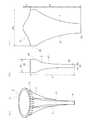
図1は,本発明の人工弁の例を示す概念図である。図1(a)は,外観図を示す。図1(b)は,第1の弁葉の概念図を示す。図1(c)は,第2の弁葉の概念図を示す。図1に示されるように,本発明の人工弁1は,リング3と,第1の弁葉5と,第2の弁葉7とを含む。第1の弁葉5と,第2の弁葉7は,同じ形状でもよいし,異なる形状であってもよい。そして,第1の弁葉5及び第2の弁葉7は,人工弁1の上部においてリング3と接続されている。第1の弁葉5及び第2の弁葉7は,上端部又は上端部付近の領域(例えば上端から0.1mm以上10mm以下の領域)が,リング3に縫い付けられていてもよい。第1の弁葉5及び第2の弁葉7は,人工弁1の下部に存在する人工弁の下部接続部9において接続される。また,第1の弁葉5及び第2の弁葉7は,下方に進むほど幅が狭くなる形状を有する。下部接続部9は,第1の弁葉5及び第2の弁葉7の下端であってもよいし,下端付近の領域(例えば下端から0.1mm以上10mm以下の領域)に位置してもよい。 FIG. 1 is a conceptual diagram showing an example of the artificial valve of the present invention. FIG. 1A shows an external view. FIG.1 (b) shows the conceptual diagram of a 1st valve leaf. FIG.1 (c) shows the conceptual diagram of a 2nd leaflet. As shown in FIG. 1, the
リング3は,例えば,直径が30mm以上60mm以下(又は35mm以上55mm以下,40mm以上50mm以下)の輪状の形状を有する。リング3は,左心房の形状に適合するように楕円状であってもよいし,円状であってもよい。リング3は,生体適合性のある素材により製造されるものが好ましい。リングは,折り畳むことができ,展開することができるように金属(ばね)を含んでいてもよいし,樹脂性のものであってもよい。樹脂製のリングの例は,シリコン樹脂のものである。 The
第1の弁葉5及び第2の弁葉7は,人工弁に用いられる公知の素材を用いることができる。弁葉の素材の例は,ヒト幹細胞由来の膜,哺乳動物(例えば,ブタ,牛,馬)由来の組織である。弁尖の素材の別の例は,患者由来の組織を用いるものである。患者由来の組織は,患者から採取した生体組織材料を用いて,再生したものであってもよい。生体組織材料は,生体由来組織を形成するうえで必要な物質である。生体組織材料の例は,線維芽細胞、平滑筋細胞、内皮細胞、幹細胞、ES細胞、iPS細胞等の動物細胞、各種たんぱく質類(コラーゲン、エラスチン)、ヒアルロン酸等の糖類、細胞成長因子、及びサイトカインである。人工弁形成用基材を生体組織材料の存在する環境下におくことにより,人工弁形成用基材の表面に加工可能な結合組織体を形成できる。弁葉の素材の別の例は,樹脂やプラスチックである。 For the
この人工弁は,第1の弁葉5及び第2の弁葉7の下端が,幅が狭い形状を有している。このため,この人工弁を左心室から挿入し,リングを左心房において開いた後に,人工弁を挿入した左心室の部位や左室心尖部53に,第1の弁葉5及び第2の弁葉7の下端を埋め込むことができる。このため,この人工弁は,患者の心臓内において安定することとなる。すなわち,本発明の人工弁は,リングが患者の左心房内に位置した場合に,人工弁の末端が左室心尖部まで到達する大きさか,又は左室心尖部を超える長さを有しているものが好ましい。つまりこの人工弁は,僧帽弁の補助用の人工弁であることが好ましく,リングが左心房内に残留し,人工弁の弁葉の下部が左室心尖部に到達し,人工弁の長さを調整したうえで,人工弁の弁葉の下部を左室心尖部に固定する人工弁である。 In this artificial valve, the lower ends of the
図1(b)に示される第1の弁葉5について説明する。この弁葉は,リング3に縫い付けられる部分である上端21の幅W1は,例えば,30mm以上90mm以下である。幅W1は40mm以上80mm以下でもよいし,45mm以上70mm以下でもよい。第1の弁葉は,リングの15%以上45%以下の部分を被覆するものが好ましく,20%以上40%以下でもよいし,20%以上30%以下でもよい。図1(b)に示される弁葉5は,その上部に幅が一様な部位が存在する。この部位は,第2の弁葉との接続部位25である。この部位25の長さ(高さ)の例は,1mm以上10mm以下であり,2mm以上8mm以下でもよいし,4mm以上8mm以下でもよい。この例では,幅が一定の上部から下端23に向かうにしたがって曲線的に幅が狭くなる部位27が存在する。下端23の幅の例は,2mm以上20mm以下であり,3mm以上10mm以下でもよいし,3mm以上5mm以下でもよい。第1の弁葉5の高さL1は,20mm以上70mm以下であり,25mm以上65mm以下でもよいし,30mm以上40mm以下でもよいし,40mm以上70mm以下でもよいし,40mm以上60mm以下でもよい。弁葉の具体的なサイズは,例えば,患者の心臓の形状や血液の逆流の程度,及び病状を考慮して設計すればよい。 The
図1(c)に示される第2の弁葉7は,基本的には第1の弁葉5と同様に製造すればよい。一方,第2の弁葉を第1の弁葉よりも厚くしてもよい。そうすることで,2つの弁葉に剛性の相違が生まれ,効果的に血液の逆流を防止できることとなる。第1の弁葉の平均厚さをd1とし,第2の弁葉の厚さをd2とする。するとd1とd2は同じでもよい。一方,2つの弁葉の厚さが異なる場合,1.01d1≦d2≦3d1でもよいし,1.05d1≦d2≦2.5d1でもよいし,1.5d1≦d2≦2.5d1でもよいし,1.75d1≦d2≦2.5d1でもよい。図1(c)におけるL3は,図1(b)のL1と同程度とすればよい。また,第2の弁葉の下端33は,第1の弁葉の下端23と同程度の幅とすればよい。第2の弁葉の上部31は,リングの形状に合うようになだらかな起伏(凸部)31が存在する。また,第2の弁葉の上部には,幅が一定な部分である接続部位35が存在する。この部位は,第1の弁葉の接続部位25と縫い合わされてもよい。この例では,幅が一定の上部から下端33に向かうにしたがって曲線的に幅が狭くなる部位37が存在する。The
この人工弁は,第1の弁葉5の上部と,第2の弁葉7の上部が,人工弁1の上部接続部11において接続されているものであってもよい。すると,2つの弁葉が結合されるので,弁葉の安定性が高まることとなる。さらに,この人工弁は,第1の弁葉と第2の弁葉の下部が,下部接続部9において接続される。すると,これら接続部の間の部分が膨らんだり,しぼんだりできることになる。この動作により,この人工弁は,血液の逆流を防止できる。 In this artificial valve, the upper part of the
この人工弁は,リング3が,折りたたむことができ,左心房内で開くことができるものであることが好ましい。このような性質を有していると,この人工弁は,カテーテル的に心臓内に挿入及び設置できるため,人工弁を設置するために開胸手術が不要となる。 The prosthetic valve is preferably such that the
この人工弁は,リング3,第1の弁葉5,及び第2の弁葉7のいずれかは,左心房壁と係止するための係止部13を有しているものが好ましい。係止部13は,第1の弁葉5及び第2の弁葉7のいずれか又は両方に設けられた左心房壁との癒着部であってもよい。このような係止部13を有しているので,この人工弁は,縫合することで左心房に固定する必要が無くなる。 In this artificial valve, it is preferable that any one of the
係止部13の例は,図1に図示されるように,リング13の外周に設けられた複数のフックである。このフックが左心房に係り,リング13が左心房内で変動することを防止する。係止部13は,リング13に設けられた複数の微小突起であってもよい。突起が大きすぎると心房を傷つけることとなるため,突起の長さ(高さ)の例は,0.1mm以上5mm以下であり,0.2mm以上3mm以下でも,0.2mm以上1mm以下でもよい。この突起は,生体親和性のある材料で製造されればよい。この突起は,表面にコーティング層を有してもよい。コーティング層は,例えばトレハロースや各種薬剤を含んでもよい。また,コーティング層は,リング又は弁葉上部と左心房とが癒着するようにフィブリンなどの癒着材又は生体内で癒着物質を分泌させる物質を含んでもよい。第1の弁葉5又は第2の弁葉7が癒着部を有する場合,例えば,弁葉の上部(例えば,リング13に接続される部位から20mm以内の領域,又は15mm以内の領域)に複数の凹凸や複数の突起を有する者であってもよい。また,弁葉の上部に癒着物質を塗布したことによって製造される癒着惹起層を有していてもよい。 An example of the locking
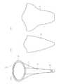
図2は,本発明の人工弁の例を示す概念図である。図2(a)は,外観図を示す。図2(b)は,第1の弁葉の概念図を示す。図2(c)は,第2の弁葉の概念図を示す。図2に示されるように,本発明の人工弁は,第1及び第2の弁葉でリングを覆う必要がない。この人工弁は,第1の弁葉5又は第2の弁葉7がリング3と接続される領域が,リング3の30%以上99%以下の領域(又は35%以上90%以下の領域)であってもよい。上記の特許文献1(特許第5392539号公報)のものは,リングの半分程度の領域を2つの弁葉で覆っている。この例では,第1の弁葉(図2(b))及び第2の弁葉(図2(c))に幅が一定の部分が存在せず,上端から下端に向かうにしたがって幅が狭っているものの,その曲線には変曲点が複数存在している。すなわち,弁葉の形状は,一様に狭くなるものでなくてもよく,下端に向かう途中において幅が広くなるものや,起伏に富んだものであっても構わない。 FIG. 2 is a conceptual diagram showing an example of the artificial valve of the present invention. FIG. 2A shows an external view. FIG.2 (b) shows the conceptual diagram of a 1st valve leaf. FIG.2 (c) shows the conceptual diagram of a 2nd leaflet. As shown in FIG. 2, the prosthetic valve of the present invention does not need to cover the ring with the first and second leaflets. In this artificial valve, the region where the
次に,本発明の人工弁の製造方法の例について説明する。図3は,心臓周辺の臓器を説明するための概念図である。図中の矢印は,血流の方向を示す。本発明の人工弁は,基本的には,僧帽弁51の機能を補助するものである。まずは,患者の心臓の大きさ,左心室を構成する筋肉53の状態,左心室55及び左心房57の形状,僧帽弁閉鎖不全症のステージ(僧帽弁の機能)といった情報を収集する。そして,本発明の人工弁を用いることを決めた場合,人工弁の素材や大きさを決定する。弁葉の膜の素材によっては,再生医療を行い,膜の素材を得る。膜から弁葉を切りとる。その後,必要に応じて弁葉に処理を施す。そして,弁葉の上部をリングに縫い付ける。一方,弁葉の下部同士を縫い付ける。このようにして人工弁を得る。この例は,人工弁の製造方法の一例であって,例えば,あらかじめいくつかのサイズの人工弁や弁膜を用意しておいて,患者に合わせて組み立ててもよい。 Next, the example of the manufacturing method of the artificial valve of this invention is demonstrated. FIG. 3 is a conceptual diagram for explaining organs around the heart. The arrows in the figure indicate the direction of blood flow. The artificial valve of the present invention basically assists the function of the
図4は,本発明の人工弁の使用例を示す概念図である。この例では,全身麻酔下に左小開胸アプローチを行う。人工弁は,折り畳まれた状態でシース(収容部)61に収容され,血管を通して左心室付近まで伝搬される。そして,シース61を,左室心尖部53を突き抜け,左心室55を通り,僧帽弁前尖・後尖の間を通過させ,左心房内に到達させる。人工弁が左心房に存在する状態で,シース61を後退させる。すると,左心房内でリングが展開する。その後,エコーガイドを用いて患者の僧帽弁と人工弁のアライメントをとり,係止部(鉤)13を左心房壁に固定する。人工弁の下端を左室心尖部53の外に出しエコーで人工弁の接合を見ながら,人工弁の長さを調整する。長さを決定したら弁葉を左室心尖部53に固定する。人工弁は自己弁の上に重ねるように留置される。このようにすることで,患者の自己弁もこれまでどおり動くこととなる。また,自己弁及び人工弁ともに左室壁との連続性が保たれる。 FIG. 4 is a conceptual diagram showing an example of use of the artificial valve of the present invention. In this example, the left small thoracotomy approach is performed under general anesthesia. The artificial valve is accommodated in a sheath (accommodating portion) 61 in a folded state, and propagates through the blood vessel to the vicinity of the left ventricle. Then, the
本発明や医療機器の分野で利用されうる。 It can be used in the field of the present invention and medical devices.
1 人工弁
3 リング
5 第1の弁葉
7 第2の弁葉
9 下部接続部
13 係止部
DESCRIPTION OF
Claims (7)
Translated fromJapanese第1の弁葉(5)及び第2の弁葉(7)は,前記人工弁(1)の上部において前記リング(3)と接続され,
第1の弁葉(5)及び第2の弁葉(7)は,前記人工弁(1)の下部に存在する下部接続部(9)において接続され,
第1の弁葉(5)及び第2の弁葉(7)は,前記リング(3)の下部において,下方に進むほど幅が狭くなる部分を有し,下端において幅が最も狭い形状を有する,
僧帽弁の機能を補助する人工弁。A prosthetic valve (1) comprising a ring (3), a first leaflet (5) and a second leaflet (7),
The first leaflet (5) and the second leaflet (7) are connected to the ring (3) at the top of the artificial valve (1),
The first leaflet (5) and the second leaflet (7) are connected at a lower connection part (9) existing at the lower part of the artificial valve (1),
The first leaflet (5) and the second leaflet (7),in the lower portion of the ring (3),have a width narrowerportions as proceedsdownward, with thenarrowest shape width at the lower end ,
A prosthetic valvethat assists the function of the mitral valve .
第1の弁葉(5)の上部と,第2の弁葉(7)の上部は,上部接続部(11)において接続されている,人工弁。The artificial valve according to claim 1,
An artificial valve in which the upper part of the first leaflet (5) and the upper part of the second leaflet (7) are connected at the upper connection part (11).
第1の弁葉(5)又は第2の弁葉(7)は,前記リング(3)の円周を100%としたとき,前記リング(3)の円周の30%以上99%以下の部分において接続される,人工弁。The artificial valve according to claim 1,
The first leaflet (5) or the second leaflet (7)is 30% or more and 99% or lessof thecircumference of the ring (3)when the circumference of the ring (3) is 100%. Artificial valveconnected at the part .
前記リング(3)は,折りたたむことができ,左心房内で開くことができる,人工弁。The artificial valve according to claim 1,
The ring (3) is a prosthetic valve that can be folded and opened in the left atrium.
前記リングは,直径が30mm以上60mm以下の輪状の形状を有する,人工弁。The artificial valve according to claim 1,
The ring is a prosthetic valve having a ring shape with a diameter of 30 mm to 60 mm.
前記リング(3),第1の弁葉(5),及び第2の弁葉(7)のいずれかは,左心房壁と係止するための係止部(13)を有する,人工弁。The artificial valve according to claim 1,
It said ring (3), the first leaflet (5), and either of the second leaflet (7),a locking part for locking the left atrialwall (13), the prosthetic valve.
前記係止部(13)は,第1の弁葉(5)及び第2の弁葉(7)のいずれか又は両方に設けられた左心房壁との癒着部である,人工弁。
The artificial valve according to claim 6,
The said locking part (13) is an artificial valve which is an adhesion part with the left atrial wall provided in either or both of the 1st valve leaf (5) and the 2nd valve leaf (7).
Priority Applications (7)
| Application Number | Priority Date | Filing Date | Title |
|---|---|---|---|
| JP2017027391AJP6159041B1 (en) | 2017-02-17 | 2017-02-17 | Artificial valve |
| CN201880012171.2ACN110337280A (en) | 2017-02-17 | 2018-02-16 | Artificial heart valve |
| US16/486,501US20190358034A1 (en) | 2017-02-17 | 2018-02-16 | Artificial heart valve |
| EP18753553.9AEP3583917A4 (en) | 2017-02-17 | 2018-02-16 | ARTIFICIAL HEART VALVE |
| CN202210855382.0ACN115153965A (en) | 2017-02-17 | 2018-02-16 | artificial heart valve |
| PCT/JP2018/005444WO2018151247A1 (en) | 2017-02-17 | 2018-02-16 | Artificial heart valve |
| US17/403,889US12336906B2 (en) | 2017-02-17 | 2021-08-17 | Artificial heart valve |
Applications Claiming Priority (1)
| Application Number | Priority Date | Filing Date | Title |
|---|---|---|---|
| JP2017027391AJP6159041B1 (en) | 2017-02-17 | 2017-02-17 | Artificial valve |
Publications (2)
| Publication Number | Publication Date |
|---|---|
| JP6159041B1true JP6159041B1 (en) | 2017-07-05 |
| JP2018130409A JP2018130409A (en) | 2018-08-23 |
Family
ID=59273024
Family Applications (1)
| Application Number | Title | Priority Date | Filing Date |
|---|---|---|---|
| JP2017027391AActiveJP6159041B1 (en) | 2017-02-17 | 2017-02-17 | Artificial valve |
Country Status (1)
| Country | Link |
|---|---|
| JP (1) | JP6159041B1 (en) |
Cited By (2)
| Publication number | Priority date | Publication date | Assignee | Title |
|---|---|---|---|---|
| WO2018151247A1 (en)* | 2017-02-17 | 2018-08-23 | 実 田端 | Artificial heart valve |
| JP2018202175A (en)* | 2017-06-08 | 2018-12-27 | 実 田端 | Prosthetic heart valve |
Family Cites Families (5)
| Publication number | Priority date | Publication date | Assignee | Title |
|---|---|---|---|---|
| US4583535A (en)* | 1980-08-07 | 1986-04-22 | Saffo John J | Protection mask |
| US20060195183A1 (en)* | 2005-02-18 | 2006-08-31 | The Cleveland Clinic Foundation | Apparatus and methods for replacing a cardiac valve |
| JP5392539B2 (en)* | 2008-12-25 | 2014-01-22 | 学校法人早稲田大学 | Stentless artificial mitral valve and prosthetic leaflet |
| JP2015536744A (en)* | 2012-12-06 | 2015-12-24 | マイトラリクス リミテッドMitralix Ltd. | Device and method for replacement of heart valve function |
| US10052409B2 (en)* | 2013-05-03 | 2018-08-21 | Cormatrix Cardiovascular, Inc. | Prosthetic tissue valves |
- 2017
- 2017-02-17JPJP2017027391Apatent/JP6159041B1/enactiveActive
Cited By (3)
| Publication number | Priority date | Publication date | Assignee | Title |
|---|---|---|---|---|
| WO2018151247A1 (en)* | 2017-02-17 | 2018-08-23 | 実 田端 | Artificial heart valve |
| JP2018202175A (en)* | 2017-06-08 | 2018-12-27 | 実 田端 | Prosthetic heart valve |
| JP2018202132A (en)* | 2017-06-08 | 2018-12-27 | 実 田端 | Prosthetic heart valve |
Also Published As
| Publication number | Publication date |
|---|---|
| JP2018130409A (en) | 2018-08-23 |
Similar Documents
| Publication | Publication Date | Title |
|---|---|---|
| US12279955B2 (en) | Mitral or tricuspid repair systems with multi-directional anchors | |
| US12427017B2 (en) | Methods, devices and systems for transcatheter mitral valve replacement in a double-orifice mitral valve | |
| CN104771247B (en) | A kind of device and method for treating mitral reflux | |
| US9259313B2 (en) | Heart valve | |
| CN100333704C (en) | Methods and devices for heart valve therapy | |
| JP6814042B2 (en) | Devices and methods for the treatment of mitral regurgitation | |
| JP2020531189A (en) | Diameter catheter device for treating mitral regurgitation | |
| KR20190020038A (en) | Heart valve recovery device and method of implanting the same | |
| JP2010533037A (en) | Aortic valve reinforcement device in body wall and reinforced living aortic valve | |
| US12336906B2 (en) | Artificial heart valve | |
| CN101299976A (en) | Prosthesis for ascending aortic segment and method for surgical treatment of aortic valve leakage | |
| EP3852681A1 (en) | A medical device for improving function of a heart valve | |
| JP6159041B1 (en) | Artificial valve | |
| JP6388463B1 (en) | Prosthetic heart valve | |
| WO2018151247A1 (en) | Artificial heart valve |
Legal Events
| Date | Code | Title | Description |
|---|---|---|---|
| A521 | Request for written amendment filed | Free format text:JAPANESE INTERMEDIATE CODE: A523 Effective date:20170404 | |
| TRDD | Decision of grant or rejection written | ||
| A01 | Written decision to grant a patent or to grant a registration (utility model) | Free format text:JAPANESE INTERMEDIATE CODE: A01 Effective date:20170606 | |
| A61 | First payment of annual fees (during grant procedure) | Free format text:JAPANESE INTERMEDIATE CODE: A61 Effective date:20170608 | |
| R150 | Certificate of patent or registration of utility model | Ref document number:6159041 Country of ref document:JP Free format text:JAPANESE INTERMEDIATE CODE: R150 | |
| R250 | Receipt of annual fees | Free format text:JAPANESE INTERMEDIATE CODE: R250 | |
| R250 | Receipt of annual fees | Free format text:JAPANESE INTERMEDIATE CODE: R250 | |
| R250 | Receipt of annual fees | Free format text:JAPANESE INTERMEDIATE CODE: R250 | |
| R250 | Receipt of annual fees | Free format text:JAPANESE INTERMEDIATE CODE: R250 | |
| R250 | Receipt of annual fees | Free format text:JAPANESE INTERMEDIATE CODE: R250 | |
| R250 | Receipt of annual fees | Free format text:JAPANESE INTERMEDIATE CODE: R250 |