JP6158867B2 - Inspection method of electrolyte membrane / electrode structure with resin frame - Google Patents
Inspection method of electrolyte membrane / electrode structure with resin frameDownload PDFInfo
- Publication number
- JP6158867B2 JP6158867B2JP2015149323AJP2015149323AJP6158867B2JP 6158867 B2JP6158867 B2JP 6158867B2JP 2015149323 AJP2015149323 AJP 2015149323AJP 2015149323 AJP2015149323 AJP 2015149323AJP 6158867 B2JP6158867 B2JP 6158867B2
- Authority
- JP
- Japan
- Prior art keywords
- electrolyte membrane
- electrode
- polymer electrolyte
- solid polymer
- resin frame
- Prior art date
- Legal status (The legal status is an assumption and is not a legal conclusion. Google has not performed a legal analysis and makes no representation as to the accuracy of the status listed.)
- Active
Links
Images


Classifications
- H—ELECTRICITY
- H01—ELECTRIC ELEMENTS
- H01M—PROCESSES OR MEANS, e.g. BATTERIES, FOR THE DIRECT CONVERSION OF CHEMICAL ENERGY INTO ELECTRICAL ENERGY
- H01M8/00—Fuel cells; Manufacture thereof
- H01M8/02—Details
- H01M8/0271—Sealing or supporting means around electrodes, matrices or membranes
- H01M8/0273—Sealing or supporting means around electrodes, matrices or membranes with sealing or supporting means in the form of a frame
- H—ELECTRICITY
- H01—ELECTRIC ELEMENTS
- H01M—PROCESSES OR MEANS, e.g. BATTERIES, FOR THE DIRECT CONVERSION OF CHEMICAL ENERGY INTO ELECTRICAL ENERGY
- H01M8/00—Fuel cells; Manufacture thereof
- H01M8/10—Fuel cells with solid electrolytes
- H01M8/1004—Fuel cells with solid electrolytes characterised by membrane-electrode assemblies [MEA]
- H—ELECTRICITY
- H01—ELECTRIC ELEMENTS
- H01M—PROCESSES OR MEANS, e.g. BATTERIES, FOR THE DIRECT CONVERSION OF CHEMICAL ENERGY INTO ELECTRICAL ENERGY
- H01M8/00—Fuel cells; Manufacture thereof
- H01M8/24—Grouping of fuel cells, e.g. stacking of fuel cells
- H01M8/241—Grouping of fuel cells, e.g. stacking of fuel cells with solid or matrix-supported electrolytes
- H01M8/242—Grouping of fuel cells, e.g. stacking of fuel cells with solid or matrix-supported electrolytes comprising framed electrodes or intermediary frame-like gaskets
- H—ELECTRICITY
- H01—ELECTRIC ELEMENTS
- H01M—PROCESSES OR MEANS, e.g. BATTERIES, FOR THE DIRECT CONVERSION OF CHEMICAL ENERGY INTO ELECTRICAL ENERGY
- H01M8/00—Fuel cells; Manufacture thereof
- H01M8/10—Fuel cells with solid electrolytes
- H01M2008/1095—Fuel cells with polymeric electrolytes
- H—ELECTRICITY
- H01—ELECTRIC ELEMENTS
- H01M—PROCESSES OR MEANS, e.g. BATTERIES, FOR THE DIRECT CONVERSION OF CHEMICAL ENERGY INTO ELECTRICAL ENERGY
- H01M8/00—Fuel cells; Manufacture thereof
- H01M8/02—Details
- H01M8/0202—Collectors; Separators, e.g. bipolar separators; Interconnectors
- H01M8/0258—Collectors; Separators, e.g. bipolar separators; Interconnectors characterised by the configuration of channels, e.g. by the flow field of the reactant or coolant
- H01M8/0265—Collectors; Separators, e.g. bipolar separators; Interconnectors characterised by the configuration of channels, e.g. by the flow field of the reactant or coolant the reactant or coolant channels having varying cross sections
- H—ELECTRICITY
- H01—ELECTRIC ELEMENTS
- H01M—PROCESSES OR MEANS, e.g. BATTERIES, FOR THE DIRECT CONVERSION OF CHEMICAL ENERGY INTO ELECTRICAL ENERGY
- H01M8/00—Fuel cells; Manufacture thereof
- H01M8/04—Auxiliary arrangements, e.g. for control of pressure or for circulation of fluids
- H01M8/04082—Arrangements for control of reactant parameters, e.g. pressure or concentration
- H01M8/04089—Arrangements for control of reactant parameters, e.g. pressure or concentration of gaseous reactants
- H01M8/04104—Regulation of differential pressures
- Y—GENERAL TAGGING OF NEW TECHNOLOGICAL DEVELOPMENTS; GENERAL TAGGING OF CROSS-SECTIONAL TECHNOLOGIES SPANNING OVER SEVERAL SECTIONS OF THE IPC; TECHNICAL SUBJECTS COVERED BY FORMER USPC CROSS-REFERENCE ART COLLECTIONS [XRACs] AND DIGESTS
- Y02—TECHNOLOGIES OR APPLICATIONS FOR MITIGATION OR ADAPTATION AGAINST CLIMATE CHANGE
- Y02E—REDUCTION OF GREENHOUSE GAS [GHG] EMISSIONS, RELATED TO ENERGY GENERATION, TRANSMISSION OR DISTRIBUTION
- Y02E60/00—Enabling technologies; Technologies with a potential or indirect contribution to GHG emissions mitigation
- Y02E60/30—Hydrogen technology
- Y02E60/50—Fuel cells
Landscapes
- Chemical & Material Sciences (AREA)
- Chemical Kinetics & Catalysis (AREA)
- Electrochemistry (AREA)
- General Chemical & Material Sciences (AREA)
- Life Sciences & Earth Sciences (AREA)
- Engineering & Computer Science (AREA)
- Manufacturing & Machinery (AREA)
- Sustainable Development (AREA)
- Sustainable Energy (AREA)
- Fuel Cell (AREA)
Description
Translated fromJapanese 本発明は、固体高分子電解質膜を第1電極及び第2電極で挟んだ長方形状の電解質膜・電極構造体と、前記固体高分子電解質膜の外周を周回する長方形状の樹脂枠部材とを備える燃料電池用の樹脂枠付き電解質膜・電極構造体の検査方法に関する。
The present invention comprises a rectangular electrolyte membrane / electrode structure in which a solid polymer electrolyte membrane is sandwiched between a first electrode and a second electrode, and a rectangular resin frame member that goes around the outer periphery of the solid polymer electrolyte membrane. The presentinvention relates toan inspection method for an electrolyte membrane / electrode structure with a resin frame for a fuel cell.
一般的に、固体高分子型燃料電池は、高分子イオン交換膜からなる固体高分子電解質膜を採用している。燃料電池は、固体高分子電解質膜の一方の面にアノード電極が、前記固体高分子電解質膜の他方の面にカソード電極が、それぞれ配設された電解質膜・電極構造体(MEA)を備えている。アノード電極及びカソード電極は、それぞれ触媒層(電極触媒層)とガス拡散層(多孔質カーボン)とを有している。 In general, a polymer electrolyte fuel cell employs a polymer electrolyte membrane made of a polymer ion exchange membrane. The fuel cell includes an electrolyte membrane / electrode structure (MEA) in which an anode electrode is disposed on one surface of a solid polymer electrolyte membrane and a cathode electrode is disposed on the other surface of the solid polymer electrolyte membrane. Yes. The anode electrode and the cathode electrode each have a catalyst layer (electrode catalyst layer) and a gas diffusion layer (porous carbon).
電解質膜・電極構造体は、セパレータ(バイポーラ板)によって挟持されることにより、発電セル(単位燃料電池)が構成されている。この発電セルは、所定の数だけ積層することにより、例えば、車載用燃料電池スタックとして使用されている。 The electrolyte membrane / electrode structure is sandwiched between separators (bipolar plates) to form a power generation cell (unit fuel cell). This power generation cell is used as, for example, an in-vehicle fuel cell stack by stacking a predetermined number.
電解質膜・電極構造体では、一方のガス拡散層が固体高分子電解質膜よりも小さな平面寸法に設定されるとともに、他方のガス拡散層が前記固体高分子電解質膜と同一の平面寸法に設定される、所謂、段差MEAを構成する場合がある。その際、比較的高価な固体高分子電解質膜の使用量を削減させるとともに、薄膜状で強度が低い前記固体高分子電解質膜を保護するために、外周に樹脂枠部材を組み込んだ樹脂枠付きMEAが採用されている。 In the electrolyte membrane / electrode structure, one gas diffusion layer is set to a plane size smaller than that of the solid polymer electrolyte membrane, and the other gas diffusion layer is set to the same plane size as the solid polymer electrolyte membrane. In other words, a so-called step MEA may be formed. At that time, in order to reduce the amount of use of a relatively expensive solid polymer electrolyte membrane and to protect the solid polymer electrolyte membrane having a thin film shape and low strength, an MEA with a resin frame incorporating a resin frame member on the outer periphery Is adopted.
樹脂枠付きMEAとして、例えば、特許文献1に開示されている燃料電池用樹脂枠付き電解質膜・電極構造体が知られている。この燃料電池用樹脂枠付き電解質膜・電極構造体では、固体高分子電解質膜の一方の面には、第1電極が設けられ、前記固体高分子電解質膜の他方の面には、第2電極が設けられている。第1電極の平面寸法は、第2電極の平面寸法よりも大きな寸法に設定されるとともに、固体高分子電解質膜の外周を周回して、樹脂枠部材が設けられている。 As an MEA with a resin frame, for example, an electrolyte membrane / electrode structure with a resin frame for a fuel cell disclosed in Patent Document 1 is known. In the electrolyte membrane / electrode structure with a resin frame for a fuel cell, a first electrode is provided on one surface of the solid polymer electrolyte membrane, and a second electrode is provided on the other surface of the solid polymer electrolyte membrane. Is provided. The planar dimension of the first electrode is set to be larger than the planar dimension of the second electrode, and the resin frame member is provided around the outer periphery of the solid polymer electrolyte membrane.
樹脂枠部材は、内周基端部から第2電極側に膨出する薄肉状の内側膨出部を有し、前記内側膨出部には、電解質膜・電極構造体との当接部位を周回して接着剤が塗布される接着剤塗布部が設けられている。そして、樹脂枠部材の内周基端部には、第1電極の外周端部に樹脂材を含浸させることにより、前記第1電極と前記樹脂枠部材とが一体化された樹脂含浸部が設けられている。 The resin frame member has a thin-walled inner bulging portion that bulges from the inner peripheral base end to the second electrode side, and the inner bulging portion circulates a contact portion with the electrolyte membrane / electrode structure. An adhesive application part to which the adhesive is applied is provided. A resin impregnated portion in which the first electrode and the resin frame member are integrated is provided at the inner peripheral base end portion of the resin frame member by impregnating the outer peripheral end portion of the first electrode with a resin material. Yes.
ところで、樹脂枠部材と電解質膜・電極構造体とを接合する際に、前記樹脂枠部材の内側膨出部と第2電極の外周端部との間には、クリアランス部(隙間)が発生し易い。 By the way, when the resin frame member and the electrolyte membrane / electrode structure are joined, a clearance portion (gap) is generated between the inner bulged portion of the resin frame member and the outer peripheral end portion of the second electrode. easy.
その際、樹脂枠部材には、温度によって寸法変化が発生する一方、固体高分子電解質膜は、湿度変化(固体高分子電解質膜が保持する水分量の変化)によって膨潤及び収縮する場合が多い。 At that time, the resin frame member undergoes a dimensional change depending on the temperature, while the solid polymer electrolyte membrane often swells and contracts due to a change in humidity (change in the amount of water held by the solid polymer electrolyte membrane).
特に、固体高分子電解質膜は、方向によって寸法の変化率が異なる場合がある。例えば、固体高分子電解質膜を連続して製膜する際、乾燥工程及び巻き取り工程で応力が発生している。このため、固体高分子電解質膜には、送り方向(巻き取り方向)とこれに直交する幅方向とで、強度特性に異方性が惹起されてしまう。従って、固体高分子電解質膜は、送り方向と幅方向とで膨潤及び収縮による寸法変化が異なっている。 In particular, the solid polymer electrolyte membrane may have a different dimensional change rate depending on the direction. For example, when the solid polymer electrolyte membrane is continuously formed, stress is generated in the drying step and the winding step. For this reason, anisotropy is induced in the strength characteristics of the solid polymer electrolyte membrane in the feeding direction (winding direction) and the width direction perpendicular thereto. Therefore, the solid polymer electrolyte membrane has different dimensional changes due to swelling and shrinkage in the feeding direction and the width direction.
これにより、樹脂枠部材の変形や固体高分子電解質膜の膨潤・収縮による寸法変化によって、前記固体高分子電解質膜が大きく引張されるおそれがある。このため、クリアランス部では、例えば、アノード電極への燃料ガスの供給圧力とカソード電極への酸化剤ガスの供給圧力との差圧により、固体高分子電解質膜が座屈するように変形し、前記固体高分子電解質膜に破損が惹起される場合がある。 As a result, the solid polymer electrolyte membrane may be greatly pulled due to dimensional changes due to deformation of the resin frame member or swelling / shrinkage of the solid polymer electrolyte membrane. For this reason, in the clearance portion, for example, the solid polymer electrolyte membrane is deformed so as to buckle due to the differential pressure between the supply pressure of the fuel gas to the anode electrode and the supply pressure of the oxidant gas to the cathode electrode, and the solid Damage may be caused to the polymer electrolyte membrane.
従って、固体高分子電解質膜の破損を検査する必要があり、例えば、クリアランス部の各辺に沿って、前記固体高分子電解質膜の全周を検査する作業が行われている。しかしながら、固体高分子電解質膜の全周に亘って破損の検査を行うため、検査作業が繁雑で且つ長時間を要するという問題がある。 Therefore, it is necessary to inspect the solid polymer electrolyte membrane for breakage. For example, an operation for inspecting the entire circumference of the solid polymer electrolyte membrane is performed along each side of the clearance portion. However, since the damage is inspected over the entire circumference of the solid polymer electrolyte membrane, there is a problem that the inspection work is complicated and requires a long time.
本発明は、この種の問題を解決するものであり、クリアランス部における固体高分子電解質膜の破損検査を、短時間で且つ確実に遂行することが可能な樹脂枠付き電解質膜・電極構造体の検査方法を提供することを目的とする。
The present invention solves this type of problem, and provides a resin frame-attached electrolyte membrane / electrode structure capable of reliably performing a damage inspection of a solid polymer electrolyte membrane in a clearance portion in a short time. The purpose is to provide aninspection method .
本発明に係る燃料電池用の樹脂枠付き電解質膜・電極構造体は、長方形状の段差MEAと、長方形状の樹脂枠部材とを備えている。段差MEAは、固体高分子電解質膜の一方の面に、第1電極触媒層及び第1ガス拡散層を有する第1電極が設けられ、前記固体高分子電解質膜の他方の面に、第2電極触媒層及び第2ガス拡散層を有する第2電極が設けられている。第1電極の平面寸法は、第2電極の平面寸法よりも大きな寸法に設定されている。樹脂枠部材は、固体高分子電解質膜の外周を周回して設けられている。 An electrolyte membrane / electrode structure with a resin frame for a fuel cell according to the present invention includes a rectangular step MEA and a rectangular resin frame member. The step MEA is provided with a first electrode having a first electrode catalyst layer and a first gas diffusion layer on one surface of the solid polymer electrolyte membrane, and a second electrode on the other surface of the solid polymer electrolyte membrane. A second electrode having a catalyst layer and a second gas diffusion layer is provided. The planar dimension of the first electrode is set to be larger than the planar dimension of the second electrode. The resin frame member is provided around the outer periphery of the solid polymer electrolyte membrane.
そして、樹脂枠部材は、第2電極側に膨出する内側膨出部を有し、第2ガス拡散層の外周端部と前記内側膨出部の内周端部との間には、クリアランス部が形成されている。一方、固体高分子電解質膜は、ロール状固体高分子電解質膜を切断して使用されるとともに、前記ロール状固体高分子電解質膜の巻き取り方向が、樹脂枠部材の長辺方向に一致している。前記クリアランス部における前記固体高分子電解質膜の破損の検査は、一つの短辺部位の破損の有無を検査するだけである。
The resin frame member has an inner bulging portion that bulges toward the second electrode, and a clearance is provided between the outer peripheral end of the second gas diffusion layer and the inner peripheral end of the inner bulging portion. The part is formed. On the other hand, the solid polymer electrolyte membrane is used by cutting the roll-shaped solid polymer electrolyte membrane, and the winding direction of the roll-shaped solid polymer electrolyte membrane coincides with the long side direction of the resin frame member. Yes.The inspection of the breakage of the solid polymer electrolyte membrane in the clearance portion only inspects whether or not one short side portion is damaged.
また、第1電極は、燃料ガスが供給されるアノード電極である一方、第2電極は、酸化剤ガスが供給されるカソード電極であり、一つの短辺部位は、前記酸化剤ガスの供給側であることが好ましい。その際、第1電極に供給される燃料ガスの供給圧力が第2電極に供給される酸化剤ガスの供給圧力よりも大きな圧力に設定される固体高分子電解質膜を検査することが好ましい。
The first electrode, while the fuel gas is an anode electrode supplied, and a second electrode,Ri cathode der which oxidant gas issupplied, one of the short side site, supply of the oxidant gas side der Rukoto is preferable. At that time, it is preferableto inspect the solid polymer electrolyte membrane in which the supply pressureof the fuel gas supplied to the first electrode is set to be higher than the supply pressure of the oxidant gas supplied to the second electrode.
本発明によれば、固体高分子電解質膜は、ロール状固体高分子電解質膜の巻き取り方向と、樹脂枠部材の長辺方向とが一致している。このため、樹脂枠部材の寸法変化率の大きな方向と、固体高分子電解質膜の寸法変化率の大きな方向とが一致している。 According to the present invention, in the solid polymer electrolyte membrane, the winding direction of the roll-shaped solid polymer electrolyte membrane coincides with the long side direction of the resin frame member. For this reason, the direction in which the dimensional change rate of the resin frame member is large coincides with the direction in which the dimensional change rate of the solid polymer electrolyte membrane is large.
従って、樹脂枠部材は、温度変化によって長辺方向に比較的大きく寸法変化するため、クリアランス部の短辺に配置されている固体高分子電解質膜に大きな引張力が作用している。一方、固体高分子電解質膜は、湿度変化によって樹脂枠部材の長辺方向よりも該樹脂枠部材の短辺方向に大きく膨潤・収縮するため、クリアランス部の短辺に配置されている前記固体高分子電解質膜に大きな引張力が作用している。 Accordingly, since the resin frame member undergoes a relatively large dimensional change in the long side direction due to a temperature change, a large tensile force acts on the solid polymer electrolyte membrane disposed on the short side of the clearance portion. On the other hand, the solid polymer electrolyte membrane swells and contracts more in the short side direction of the resin frame member than in the long side direction of the resin frame member due to humidity change. A large tensile force acts on the molecular electrolyte membrane.
これにより、固体高分子電解質膜では、クリアランス部の短辺に対応する短辺部位に、前記クリアランス部の長辺に対応する長辺部位よりも大きな応力が発生している。このため、固体高分子電解質膜の短辺部位の破損の有無を検査するだけで、前記固体高分子電解質膜全体の破損の有無を確実に検査することができる。従って、クリアランス部における固体高分子電解質膜の破損検査を、短時間で且つ確実に遂行することが可能になる。 As a result, in the solid polymer electrolyte membrane, a larger stress is generated in the short side portion corresponding to the short side of the clearance portion than in the long side portion corresponding to the long side of the clearance portion. For this reason, the presence or absence of breakage of the whole solid polymer electrolyte membrane can be reliably inspected only by examining the presence or absence of breakage of the short side portion of the solid polymer electrolyte membrane. Therefore, it is possible to reliably and reliably perform a damage inspection of the solid polymer electrolyte membrane in the clearance portion in a short time.
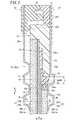
図1及び図2に示すように、本発明の実施形態に係る樹脂枠付き電解質膜・電極構造体10は、横長(又は縦長)の長方形状の固体高分子型発電セル(燃料電池)12に組み込まれる。複数の発電セル12は、例えば、矢印A方向(水平方向)又は矢印C方向(重力方向)に積層されて燃料電池スタックが構成される。燃料電池スタックは、例えば、車載用燃料電池スタックとして燃料電池電気自動車(図示せず)に搭載される。 As shown in FIGS. 1 and 2, an electrolyte membrane /
発電セル12は、樹脂枠付き電解質膜・電極構造体10を第1セパレータ14及び第2セパレータ16で挟持する。第1セパレータ14及び第2セパレータ16は、横長(又は縦長)の長方形状を有する。第1セパレータ14及び第2セパレータ16は、例えば、鋼板、ステンレス鋼板、アルミニウム板、めっき処理鋼板、あるいはその金属表面に防食用の表面処理を施した金属板や、カーボン部材等で構成される。 The
長方形状の樹脂枠付き電解質膜・電極構造体10は、長方形状の段差MEA10aを備える。図2に示すように、段差MEA10aは、例えば、パーフルオロスルホン酸の薄膜に水が含浸された固体高分子電解質膜(陽イオン交換膜)18を有する。固体高分子電解質膜18は、アノード電極(第1電極)20及びカソード電極(第2電極)22に挟持される。固体高分子電解質膜18は、フッ素系電解質の他、HC(炭化水素)系電解質を使用することができる。 The electrolyte membrane /
カソード電極22は、固体高分子電解質膜18及びアノード電極20よりも小さな平面寸法(外形寸法)を有する。なお、上記の構成に代えて、アノード電極20は、固体高分子電解質膜18及びカソード電極22よりも小さな平面寸法を有するように構成してもよい。その際、アノード電極20は、第2電極となり、カソード電極22は、第1電極となる。 The
アノード電極20は、固体高分子電解質膜18の一方の面18aに接合される第1電極触媒層20aと、前記第1電極触媒層20aに積層される第1ガス拡散層20bとを設ける。第1電極触媒層20a及び第1ガス拡散層20bは、同一の平面寸法を有するとともに、固体高分子電解質膜18と同一(又は同一未満)の平面寸法に設定される。 The
カソード電極22は、固体高分子電解質膜18の面18bに接合される第2電極触媒層22aと、前記第2電極触媒層22aに積層される第2ガス拡散層22bとを設ける。第2電極触媒層22aは、第2ガス拡散層22bの外周端部22beから外方に突出しており、前記第2ガス拡散層22bよりも大きな平面寸法を有するとともに、固体高分子電解質膜18よりも小さな平面寸法に設定される。 The
なお、第2電極触媒層22aと第2ガス拡散層22bとは、同一の平面寸法に設定されてもよく、前記第2電極触媒層22aは、前記第2ガス拡散層22bよりも小さな平面寸法を有してもよい。 The second
第1電極触媒層20aは、例えば、白金合金が表面に担持された多孔質カーボン粒子が、第1ガス拡散層20bの表面に一様に塗布されて形成される。第2電極触媒層22aは、例えば、白金合金が表面に担持された多孔質カーボン粒子が、第2ガス拡散層22bの表面に一様に塗布されて形成される。 The first
第1ガス拡散層20bは、多孔性と導電性を有するマイクロポーラス層20b(m)と、カーボンペーパ又はカーボンクロス等のカーボン層20b(c)とから形成される。第2ガス拡散層22bは、マイクロポーラス層22b(m)と、カーボンペーパ又はカーボンクロス等のカーボン層22b(c)とから形成される。 The first
第2ガス拡散層22bの平面寸法は、第1ガス拡散層20bの平面寸法よりも小さく設定される。第1電極触媒層20a及び第2電極触媒層22aは、固体高分子電解質膜18の両面に形成される。なお、マイクロポーラス層20b(m)、22b(m)は、必要に応じて用いればよく、不要にすることもできる。 The planar dimension of the second
樹脂枠付き電解質膜・電極構造体10は、固体高分子電解質膜18の外周を周回するとともに、アノード電極20及びカソード電極22に接合される樹脂枠部材24を備える。なお、樹脂枠部材24に代えて、均一な厚さを有する樹脂フィルムを用いてもよい。 The resin membrane-attached electrolyte membrane /
樹脂枠部材24は、例えば、PPS(ポリフェニレンサルファイド)、PPA(ポリフタルアミド)、PEN(ポリエチレンナフタレート)、PES(ポリエーテルサルフォン)、LCP(リキッドクリスタルポリマー)、PVDF(ポリフッ化ビニリデン)、シリコーン樹脂、フッ素樹脂、又はm−PPE(変性ポリフェニレンエーテル樹脂)等で構成される。樹脂枠部材24は、さらにPET(ポリエチレンテレフタレート)、PBT(ポリブチレンテレフタレート)又は変性ポリオレフィン等で構成される。 The
図1及び図3に示すように、樹脂枠部材24は、長方形の枠形状を有する。樹脂枠部材24は、図2及び図3に示すように、内周基端部24sから段部を介してカソード電極22側に膨出する薄肉状に形成された内側膨出部24aを有する。内側膨出部24aは、内周基端部24sから内方に所定の長さを有して延在し、固体高分子電解質膜18の外周面部18beを覆って配置される。内側膨出部24aは、内側角部にR(湾曲面)が設けられる内周長辺24aB1、24aB2と内周短辺24aC1、24aC2とを有する(図3参照)。 As shown in FIGS. 1 and 3, the
図3及び図4に示すように、内周長辺24aB1は、樹脂枠部材24の長手方向(矢印B方向)に延在する内周の上辺であり、内周長辺24aB2は、前記樹脂枠部材24の長手方向に延在する内周の下辺である。内周短辺24aC1は、樹脂枠部材24の短手方向(矢印C方向)に延在する内周の一方の側辺であり、内周短辺24aC2は、前記樹脂枠部材24の短手方向に延在する内周の他方の側辺である。 As shown in FIGS. 3 and 4, the inner peripheral long side 24aB1 is the upper side of the inner periphery extending in the longitudinal direction (arrow B direction) of the
図2に示すように、内側膨出部24aと段差MEA10aとの間には、充填室25が設けられるとともに、前記充填室25には、接着剤層26が形成される。接着剤層26には、接着剤として、例えば、液状シールやホットメルト剤が設けられる。なお、接着剤としては、液体や固体、熱可塑性や熱硬化性等に制限されない。 As shown in FIG. 2, a filling
図4に示すように、第2ガス拡散層22bの外周端部22beと内側膨出部24aの内周長辺24aB1、24aB2及び内周短辺24aC1、24aC2との間には、それぞれ距離Sだけ離間して枠形状のクリアランス部CLが形成される。クリアランス部CLの幅寸法は、内周長辺24aB1、24aB2と内周短辺24aC1、24aC2とにおいて、それぞれ同一の距離Sに設定されているが、それぞれ異なる幅寸法に設定されてもよい。 As shown in FIG. 4, there is a distance S between the outer peripheral end 22be of the second
本実施形態では、固体高分子電解質膜18は、製膜ライン(図示せず)により連続して製造されている。製膜ラインでは、パーフルオロスルホン酸のポリマー溶液が供給され、前記ポリマー溶液が乾燥工程で乾燥処理された後、巻き取り工程でロール状に巻回され、ロール状固体高分子電解質膜18Rが製造されている(図5参照)。 In the present embodiment, the solid
ロール状固体高分子電解質膜18Rには、乾燥工程及び巻き取り工程で応力が発生しており、巻き取り方向(送り方向)(以下、MD方向ともいう)と、前記MD方向に直交する幅方向(以下、TD方向ともいう)との物性に異方性が生じている。具体的には、固体高分子電解質膜18は、MD方向の膨潤・収縮の寸法変化が、TD方向の膨潤・収縮の寸法変化よりも大きい。 In the roll-shaped solid
固体高分子電解質膜18は、ロール状固体高分子電解質膜18Rを所定の長さ毎に切断して使用される。後述するように、ロール状固体高分子電解質膜18Rの巻き取り方向(MD方向)は、樹脂枠部材24の長辺方向(矢印B方向)に一致する(図4参照)。 The solid
図1に示すように、発電セル12の矢印B方向(水平方向)の一端縁部には、積層方向である矢印A方向に互いに連通して、酸化剤ガス入口連通孔30a、冷却媒体入口連通孔32a及び燃料ガス出口連通孔34bが設けられる。酸化剤ガス入口連通孔30aは、酸化剤ガス、例えば、酸素含有ガスを供給する一方、冷却媒体入口連通孔32aは、冷却媒体を供給する。燃料ガス出口連通孔34bは、燃料ガス、例えば、水素含有ガスを排出する。酸化剤ガス入口連通孔30a、冷却媒体入口連通孔32a及び燃料ガス出口連通孔34bは、矢印C方向(鉛直方向)に配列して設けられる。 As shown in FIG. 1, one end edge of the
発電セル12の矢印B方向の他端縁部には、矢印A方向に互いに連通して、燃料ガスを供給する燃料ガス入口連通孔34a、冷却媒体を排出する冷却媒体出口連通孔32b、及び酸化剤ガスを排出する酸化剤ガス出口連通孔30bが設けられる。燃料ガス入口連通孔34a、冷却媒体出口連通孔32b及び酸化剤ガス出口連通孔30bは、矢印C方向に配列して設けられる。 The other end edge of the
第2セパレータ16の樹脂枠付き電解質膜・電極構造体10に向かう面16aには、酸化剤ガス入口連通孔30aと酸化剤ガス出口連通孔30bとに連通する酸化剤ガス流路36が、矢印B方向に延在して設けられる。 An oxidant
第1セパレータ14の樹脂枠付き電解質膜・電極構造体10に向かう面14aには、燃料ガス入口連通孔34aと燃料ガス出口連通孔34bとに連通する燃料ガス流路38が、矢印B方向に延在して形成される。燃料ガス流路38を流通する燃料ガスの供給圧力は、酸化剤ガス流路36を流通する酸化剤ガスの供給圧力よりも大きな圧力に設定される。段差MEA10aでは、アノード電極20とカソード電極22との間に、反応ガス供給圧力の差による差圧(極間差圧)が惹起される。酸化剤ガスと燃料ガスとは、固体高分子電解質膜18を挟んで対向して流通する(対向流)。 A
互いに隣接する第1セパレータ14の面14bと第2セパレータ16の面16bとの間には、冷却媒体入口連通孔32aと冷却媒体出口連通孔32bとに連通する冷却媒体流路40が、矢印B方向に延在して形成される。 Between the
図1及び図2に示すように、第1セパレータ14の面14a、14bには、この第1セパレータ14の外周端部を周回して、第1シール部材42が一体化される。第2セパレータ16の面16a、16bには、この第2セパレータ16の外周端部を周回して、第2シール部材44が一体化される。 As shown in FIGS. 1 and 2, the
図2に示すように、第1シール部材42は、樹脂枠付き電解質膜・電極構造体10を構成する樹脂枠部材24に当接する第1凸状シール42aと、第2セパレータ16の第2シール部材44に当接する第2凸状シール42bとを有する。第2シール部材44は、第2凸状シール42bに当接する面がセパレータ面に沿って平面状に延在する平面シールを構成する。なお、第2凸状シール42bに代えて、第2シール部材44に凸状シール(図示せず)を設けてもよい。 As shown in FIG. 2, the
第1シール部材42及び第2シール部材44には、例えば、EPDM、NBR、フッ素ゴム、シリコーンゴム、フロロシリコーンゴム、ブチルゴム、天然ゴム、スチレンゴム、クロロプレーン又はアクリルゴム等のシール材、クッション材、あるいはパッキン材等の弾性を有するシール部材が用いられる。 For the
このように構成される発電セル12の動作について、以下に説明する。 The operation of the
先ず、図1に示すように、酸化剤ガス入口連通孔30aには、酸素含有ガス等の酸化剤ガスが供給されるとともに、燃料ガス入口連通孔34aには、水素含有ガス等の燃料ガスが供給される。さらに、冷却媒体入口連通孔32aには、純水やエチレングリコール、オイル等の冷却媒体が供給される。 First, as shown in FIG. 1, an oxidant gas such as an oxygen-containing gas is supplied to the oxidant gas
このため、酸化剤ガスは、酸化剤ガス入口連通孔30aから第2セパレータ16の酸化剤ガス流路36に導入され、矢印B方向に移動して段差MEA10aのカソード電極22に供給される。一方、燃料ガスは、燃料ガス入口連通孔34aから第1セパレータ14の燃料ガス流路38に導入される。燃料ガスは、燃料ガス流路38に沿って矢印B方向に移動し、段差MEA10aのアノード電極20に供給される。 Therefore, the oxidant gas is introduced from the oxidant gas
従って、段差MEA10aでは、カソード電極22に供給される酸化剤ガスと、アノード電極20に供給される燃料ガスとが、第2電極触媒層22a及び第1電極触媒層20a内で電気化学反応により消費されて、発電が行われる。 Therefore, in the
次いで、カソード電極22に供給されて消費された酸化剤ガスは、酸化剤ガス出口連通孔30bに沿って矢印A方向に排出される。同様に、アノード電極20に供給されて消費された燃料ガスは、燃料ガス出口連通孔34bに沿って矢印A方向に排出される。 Next, the oxidant gas consumed by being supplied to the
また、冷却媒体入口連通孔32aに供給された冷却媒体は、第1セパレータ14と第2セパレータ16との間の冷却媒体流路40に導入された後、矢印B方向に流通する。この冷却媒体は、段差MEA10aを冷却した後、冷却媒体出口連通孔32bから排出される。 The cooling medium supplied to the cooling medium
この場合、本実施形態では、図4に示すように、クリアランス部CLは、酸化剤ガス入口連通孔30aに近接し且つ矢印C方向に延在する短辺部位46aを有する。クリアランス部CLは、矢印B方向に延在する上下一対の長辺部位46bと、酸化剤ガス出口連通孔30bに近接し且つ矢印C方向に延在する短辺部位46cとを有する。 In this case, in the present embodiment, as shown in FIG. 4, the clearance CL has a
図6には、短辺部位46a、長辺部位46b及び短辺部位46cにおける固体高分子電解質膜18に発生する応力の関係が示されている。これにより、酸化剤ガス入口連通孔30aに隣接する短辺部位46aは、湿度変化が大きいために発生応力が最も大きくなっている。このため、短辺部位46aに配置される固体高分子電解質膜18の部位は、他の部位に比べて膨潤・収縮による寸法変化が大きくなっている。一方、長辺部位46b及び短辺部位46cは、湿度変化が比較的小さいため、発生応力も小さくなっている。 FIG. 6 shows the relationship among the stresses generated in the solid
そこで、図4に示すように、固体高分子電解質膜18のMD方向と、前記固体高分子電解質膜18の発生応力が最も大きな辺である短辺部位46aとを一致させている。換言すれば、ロール状固体高分子電解質膜18Rの巻き取り方向(MD方向)は、樹脂枠部材24の長辺方向(矢印B方向)に一致している。 Therefore, as shown in FIG. 4, the MD direction of the solid
従って、樹脂枠部材24は、温度変化によって長辺方向に比較的大きく寸法変化するため、クリアランス部CLの短辺部位46aに配置されている固体高分子電解質膜18に大きな引張力が作用している。一方、固体高分子電解質膜18は、湿度変化によって、特にクリアランス部CLの短辺部位46aに配置されている前記固体高分子電解質膜18が大きく膨潤・収縮し、大きな引張力が作用している。 Accordingly, since the
これにより、固体高分子電解質膜18では、クリアランス部CLの短辺部位46aに対応する部位に、前記クリアランス部CLの長辺部位46b及び他の短辺部位46cよりも大きな応力が発生している。このため、固体高分子電解質膜18の一つの短辺部位46aの破損の有無を検査するだけで、前記固体高分子電解質膜18全体の破損の有無を確実に検査することができる。従って、クリアランス部CLにおける固体高分子電解質膜18の破損検査を、短時間で且つ確実に遂行することが可能になる。 As a result, in the solid
10…樹脂枠付き電解質膜・電極構造体 10a…段差MEA
12…発電セル 14、16…セパレータ
18…固体高分子電解質膜 18be…外周面部
18R…ロール状固体高分子電解質膜 20…アノード電極
20a、22a…電極触媒層 20b、22b…ガス拡散層
22be…外周端部 22…カソード電極
24…樹脂枠部材 24a…内側膨出部
24aB1、24aB2…内周長辺 24aC1、24aC2…内周短辺
26…接着剤層 30a…酸化剤ガス入口連通孔
30b…酸化剤ガス出口連通孔 32a…冷却媒体入口連通孔
32b…冷却媒体出口連通孔 34a…燃料ガス入口連通孔
34b…燃料ガス出口連通孔 36…酸化剤ガス流路
38…燃料ガス流路 40…冷却媒体流路
42、44…シール部材10 ... Electrolyte membrane / electrode structure with
DESCRIPTION OF
Claims (3)
Translated fromJapanese前記固体高分子電解質膜の外周を周回して設けられる長方形状の樹脂枠部材と、
を備える燃料電池用の樹脂枠付き電解質膜・電極構造体の検査方法であって、
前記樹脂枠部材は、前記第2電極側に膨出する内側膨出部を有し、
前記第2ガス拡散層の外周端部と前記内側膨出部の内周端部との間には、クリアランス部が形成される一方、
前記固体高分子電解質膜は、ロール状固体高分子電解質膜を切断して使用されるとともに、
前記ロール状固体高分子電解質膜の巻き取り方向が、前記樹脂枠部材の長辺方向に一致しており、
前記クリアランス部における前記固体高分子電解質膜の破損の検査は、一つの短辺部位の破損の有無を検査するだけであることを特徴とする樹脂枠付き電解質膜・電極構造体の検査方法。A first electrode having a first electrode catalyst layer and a first gas diffusion layer is provided on one surface of the solid polymer electrolyte membrane, and a second electrode catalyst layer is provided on the other surface of the solid polymer electrolyte membrane. And a second electrode having a second gas diffusion layer, and the planar dimension of the first electrode is a rectangular step MEA set to a dimension larger than the planar dimension of the second electrode;
A rectangular resin frame member provided around the outer periphery of the solid polymer electrolyte membrane;
Amethod forinspecting an electrolyte membrane / electrode structure with a resin frame for a fuel cell comprising:
The resin frame member has an inner bulging portion that bulges toward the second electrode,
While a clearance portion is formed between the outer peripheral end portion of the second gas diffusion layer and the inner peripheral end portion of the inner bulging portion,
The solid polymer electrolyte membrane is used by cutting a roll-shaped solid polymer electrolyte membrane,
The winding direction of the roll-shaped solid polymer electrolyte membrane coincideswith the long side direction of the resin frame member,
The solid inspection of damage of the polymer electrolyte membrane,theinspection method of the resin framed membrane electrode assembly, characterized inthat it only checks for corruption of one short side region in the clearance portion.
前記第2電極は、酸化剤ガスが供給されるカソード電極であり、The second electrode is a cathode electrode to which an oxidant gas is supplied;
前記一つの短辺部位は、前記酸化剤ガスの供給側であることを特徴とする樹脂枠付き電解質膜・電極構造体の検査方法。The method for inspecting an electrolyte membrane / electrode structure with a resin frame, wherein the one short side portion is a supply side of the oxidant gas.
Priority Applications (3)
| Application Number | Priority Date | Filing Date | Title |
|---|---|---|---|
| JP2015149323AJP6158867B2 (en) | 2015-07-29 | 2015-07-29 | Inspection method of electrolyte membrane / electrode structure with resin frame |
| US15/220,392US20170033375A1 (en) | 2015-07-29 | 2016-07-27 | Resin-framed membrane electrode assembly and fuel cell |
| US16/412,420US11316178B2 (en) | 2015-07-29 | 2019-05-15 | Checking method of resin-framed membrane electrode assembly |
Applications Claiming Priority (1)
| Application Number | Priority Date | Filing Date | Title |
|---|---|---|---|
| JP2015149323AJP6158867B2 (en) | 2015-07-29 | 2015-07-29 | Inspection method of electrolyte membrane / electrode structure with resin frame |
Publications (2)
| Publication Number | Publication Date |
|---|---|
| JP2017033644A JP2017033644A (en) | 2017-02-09 |
| JP6158867B2true JP6158867B2 (en) | 2017-07-05 |
Family
ID=57883755
Family Applications (1)
| Application Number | Title | Priority Date | Filing Date |
|---|---|---|---|
| JP2015149323AActiveJP6158867B2 (en) | 2015-07-29 | 2015-07-29 | Inspection method of electrolyte membrane / electrode structure with resin frame |
Country Status (2)
| Country | Link |
|---|---|
| US (2) | US20170033375A1 (en) |
| JP (1) | JP6158867B2 (en) |
Families Citing this family (67)
| Publication number | Priority date | Publication date | Assignee | Title |
|---|---|---|---|---|
| US11904202B2 (en) | 2019-03-11 | 2024-02-20 | Rom Technolgies, Inc. | Monitoring joint extension and flexion using a sensor device securable to an upper and lower limb |
| US11471729B2 (en) | 2019-03-11 | 2022-10-18 | Rom Technologies, Inc. | System, method and apparatus for a rehabilitation machine with a simulated flywheel |
| US11185735B2 (en) | 2019-03-11 | 2021-11-30 | Rom Technologies, Inc. | System, method and apparatus for adjustable pedal crank |
| US12102878B2 (en) | 2019-05-10 | 2024-10-01 | Rehab2Fit Technologies, Inc. | Method and system for using artificial intelligence to determine a user's progress during interval training |
| US11801423B2 (en) | 2019-05-10 | 2023-10-31 | Rehab2Fit Technologies, Inc. | Method and system for using artificial intelligence to interact with a user of an exercise device during an exercise session |
| US11433276B2 (en) | 2019-05-10 | 2022-09-06 | Rehab2Fit Technologies, Inc. | Method and system for using artificial intelligence to independently adjust resistance of pedals based on leg strength |
| US11904207B2 (en) | 2019-05-10 | 2024-02-20 | Rehab2Fit Technologies, Inc. | Method and system for using artificial intelligence to present a user interface representing a user's progress in various domains |
| US11957960B2 (en) | 2019-05-10 | 2024-04-16 | Rehab2Fit Technologies Inc. | Method and system for using artificial intelligence to adjust pedal resistance |
| KR102845708B1 (en)* | 2019-05-16 | 2025-08-12 | 현대자동차주식회사 | Elastomer cell frame for fuel cell and Manufacturing method thereof and Fuel cell stack comprising thereof |
| US11071597B2 (en) | 2019-10-03 | 2021-07-27 | Rom Technologies, Inc. | Telemedicine for orthopedic treatment |
| US12402804B2 (en) | 2019-09-17 | 2025-09-02 | Rom Technologies, Inc. | Wearable device for coupling to a user, and measuring and monitoring user activity |
| US11701548B2 (en) | 2019-10-07 | 2023-07-18 | Rom Technologies, Inc. | Computer-implemented questionnaire for orthopedic treatment |
| CN112563545B (en)* | 2019-09-26 | 2022-03-04 | 群翌能源股份有限公司 | Membrane electrode assembly of proton exchange membrane fuel cell and assembly method thereof |
| US12154672B2 (en) | 2019-10-03 | 2024-11-26 | Rom Technologies, Inc. | Method and system for implementing dynamic treatment environments based on patient information |
| US11101028B2 (en) | 2019-10-03 | 2021-08-24 | Rom Technologies, Inc. | Method and system using artificial intelligence to monitor user characteristics during a telemedicine session |
| US12420145B2 (en) | 2019-10-03 | 2025-09-23 | Rom Technologies, Inc. | Systems and methods of using artificial intelligence and machine learning for generating alignment plans to align a user with an imaging sensor during a treatment session |
| US12347543B2 (en) | 2019-10-03 | 2025-07-01 | Rom Technologies, Inc. | Systems and methods for using artificial intelligence to implement a cardio protocol via a relay-based system |
| US11915816B2 (en) | 2019-10-03 | 2024-02-27 | Rom Technologies, Inc. | Systems and methods of using artificial intelligence and machine learning in a telemedical environment to predict user disease states |
| US11955222B2 (en) | 2019-10-03 | 2024-04-09 | Rom Technologies, Inc. | System and method for determining, based on advanced metrics of actual performance of an electromechanical machine, medical procedure eligibility in order to ascertain survivability rates and measures of quality-of-life criteria |
| US11978559B2 (en) | 2019-10-03 | 2024-05-07 | Rom Technologies, Inc. | Systems and methods for remotely-enabled identification of a user infection |
| US12230381B2 (en) | 2019-10-03 | 2025-02-18 | Rom Technologies, Inc. | System and method for an enhanced healthcare professional user interface displaying measurement information for a plurality of users |
| US11830601B2 (en) | 2019-10-03 | 2023-11-28 | Rom Technologies, Inc. | System and method for facilitating cardiac rehabilitation among eligible users |
| US12087426B2 (en) | 2019-10-03 | 2024-09-10 | Rom Technologies, Inc. | Systems and methods for using AI ML to predict, based on data analytics or big data, an optimal number or range of rehabilitation sessions for a user |
| US12246222B2 (en) | 2019-10-03 | 2025-03-11 | Rom Technologies, Inc. | Method and system for using artificial intelligence to assign patients to cohorts and dynamically controlling a treatment apparatus based on the assignment during an adaptive telemedical session |
| US12150792B2 (en) | 2019-10-03 | 2024-11-26 | Rom Technologies, Inc. | Augmented reality placement of goniometer or other sensors |
| US12062425B2 (en) | 2019-10-03 | 2024-08-13 | Rom Technologies, Inc. | System and method for implementing a cardiac rehabilitation protocol by using artificial intelligence and standardized measurements |
| US12380984B2 (en) | 2019-10-03 | 2025-08-05 | Rom Technologies, Inc. | Systems and methods for using artificial intelligence and machine learning to generate treatment plans having dynamically tailored cardiac protocols for users to manage a state of an electromechanical machine |
| US12224052B2 (en) | 2019-10-03 | 2025-02-11 | Rom Technologies, Inc. | System and method for using AI, machine learning and telemedicine for long-term care via an electromechanical machine |
| US11915815B2 (en) | 2019-10-03 | 2024-02-27 | Rom Technologies, Inc. | System and method for using artificial intelligence and machine learning and generic risk factors to improve cardiovascular health such that the need for additional cardiac interventions is mitigated |
| US12020799B2 (en) | 2019-10-03 | 2024-06-25 | Rom Technologies, Inc. | Rowing machines, systems including rowing machines, and methods for using rowing machines to perform treatment plans for rehabilitation |
| US11961603B2 (en) | 2019-10-03 | 2024-04-16 | Rom Technologies, Inc. | System and method for using AI ML and telemedicine to perform bariatric rehabilitation via an electromechanical machine |
| US11887717B2 (en) | 2019-10-03 | 2024-01-30 | Rom Technologies, Inc. | System and method for using AI, machine learning and telemedicine to perform pulmonary rehabilitation via an electromechanical machine |
| US11923065B2 (en) | 2019-10-03 | 2024-03-05 | Rom Technologies, Inc. | Systems and methods for using artificial intelligence and machine learning to detect abnormal heart rhythms of a user performing a treatment plan with an electromechanical machine |
| US12230382B2 (en) | 2019-10-03 | 2025-02-18 | Rom Technologies, Inc. | Systems and methods for using artificial intelligence and machine learning to predict a probability of an undesired medical event occurring during a treatment plan |
| US20210134412A1 (en) | 2019-10-03 | 2021-05-06 | Rom Technologies, Inc. | System and method for processing medical claims using biometric signatures |
| US11265234B2 (en) | 2019-10-03 | 2022-03-01 | Rom Technologies, Inc. | System and method for transmitting data and ordering asynchronous data |
| US11087865B2 (en) | 2019-10-03 | 2021-08-10 | Rom Technologies, Inc. | System and method for use of treatment device to reduce pain medication dependency |
| US11282608B2 (en) | 2019-10-03 | 2022-03-22 | Rom Technologies, Inc. | Method and system for using artificial intelligence and machine learning to provide recommendations to a healthcare provider in or near real-time during a telemedicine session |
| US11955220B2 (en) | 2019-10-03 | 2024-04-09 | Rom Technologies, Inc. | System and method for using AI/ML and telemedicine for invasive surgical treatment to determine a cardiac treatment plan that uses an electromechanical machine |
| US11515021B2 (en) | 2019-10-03 | 2022-11-29 | Rom Technologies, Inc. | Method and system to analytically optimize telehealth practice-based billing processes and revenue while enabling regulatory compliance |
| US20230245750A1 (en) | 2019-10-03 | 2023-08-03 | Rom Technologies, Inc. | Systems and methods for using elliptical machine to perform cardiovascular rehabilitation |
| US11955223B2 (en) | 2019-10-03 | 2024-04-09 | Rom Technologies, Inc. | System and method for using artificial intelligence and machine learning to provide an enhanced user interface presenting data pertaining to cardiac health, bariatric health, pulmonary health, and/or cardio-oncologic health for the purpose of performing preventative actions |
| US11756666B2 (en) | 2019-10-03 | 2023-09-12 | Rom Technologies, Inc. | Systems and methods to enable communication detection between devices and performance of a preventative action |
| US12327623B2 (en) | 2019-10-03 | 2025-06-10 | Rom Technologies, Inc. | System and method for processing medical claims |
| US11515028B2 (en) | 2019-10-03 | 2022-11-29 | Rom Technologies, Inc. | Method and system for using artificial intelligence and machine learning to create optimal treatment plans based on monetary value amount generated and/or patient outcome |
| US11075000B2 (en) | 2019-10-03 | 2021-07-27 | Rom Technologies, Inc. | Method and system for using virtual avatars associated with medical professionals during exercise sessions |
| US12020800B2 (en) | 2019-10-03 | 2024-06-25 | Rom Technologies, Inc. | System and method for using AI/ML and telemedicine to integrate rehabilitation for a plurality of comorbid conditions |
| US11139060B2 (en) | 2019-10-03 | 2021-10-05 | Rom Technologies, Inc. | Method and system for creating an immersive enhanced reality-driven exercise experience for a user |
| US12420143B1 (en) | 2019-10-03 | 2025-09-23 | Rom Technologies, Inc. | System and method for enabling residentially-based cardiac rehabilitation by using an electromechanical machine and educational content to mitigate risk factors and optimize user behavior |
| US11282599B2 (en) | 2019-10-03 | 2022-03-22 | Rom Technologies, Inc. | System and method for use of telemedicine-enabled rehabilitative hardware and for encouragement of rehabilitative compliance through patient-based virtual shared sessions |
| US12220201B2 (en) | 2019-10-03 | 2025-02-11 | Rom Technologies, Inc. | Remote examination through augmented reality |
| US12191018B2 (en) | 2019-10-03 | 2025-01-07 | Rom Technologies, Inc. | System and method for using artificial intelligence in telemedicine-enabled hardware to optimize rehabilitative routines capable of enabling remote rehabilitative compliance |
| US11069436B2 (en) | 2019-10-03 | 2021-07-20 | Rom Technologies, Inc. | System and method for use of telemedicine-enabled rehabilitative hardware and for encouraging rehabilitative compliance through patient-based virtual shared sessions with patient-enabled mutual encouragement across simulated social networks |
| US11955221B2 (en) | 2019-10-03 | 2024-04-09 | Rom Technologies, Inc. | System and method for using AI/ML to generate treatment plans to stimulate preferred angiogenesis |
| US12100499B2 (en) | 2020-08-06 | 2024-09-24 | Rom Technologies, Inc. | Method and system for using artificial intelligence and machine learning to create optimal treatment plans based on monetary value amount generated and/or patient outcome |
| US11282604B2 (en) | 2019-10-03 | 2022-03-22 | Rom Technologies, Inc. | Method and system for use of telemedicine-enabled rehabilitative equipment for prediction of secondary disease |
| US11317975B2 (en) | 2019-10-03 | 2022-05-03 | Rom Technologies, Inc. | Method and system for treating patients via telemedicine using sensor data from rehabilitation or exercise equipment |
| US12427376B2 (en) | 2019-10-03 | 2025-09-30 | Rom Technologies, Inc. | Systems and methods for an artificial intelligence engine to optimize a peak performance |
| US11270795B2 (en) | 2019-10-03 | 2022-03-08 | Rom Technologies, Inc. | Method and system for enabling physician-smart virtual conference rooms for use in a telehealth context |
| US12176089B2 (en) | 2019-10-03 | 2024-12-24 | Rom Technologies, Inc. | System and method for using AI ML and telemedicine for cardio-oncologic rehabilitation via an electromechanical machine |
| US11826613B2 (en) | 2019-10-21 | 2023-11-28 | Rom Technologies, Inc. | Persuasive motivation for orthopedic treatment |
| US12424319B2 (en) | 2019-11-06 | 2025-09-23 | Rom Technologies, Inc. | System for remote treatment utilizing privacy controls |
| CN111029610B (en)* | 2019-11-11 | 2021-07-30 | 珠海格力电器股份有限公司 | Hydrogen fuel cell bipolar plate and hydrogen fuel cell |
| CN111129539B (en)* | 2019-12-28 | 2021-05-28 | 一汽解放汽车有限公司 | Fuel cell membrane electrode sealing device and preparation method thereof |
| US11107591B1 (en) | 2020-04-23 | 2021-08-31 | Rom Technologies, Inc. | Method and system for describing and recommending optimal treatment plans in adaptive telemedical or other contexts |
| WO2021262809A1 (en) | 2020-06-26 | 2021-12-30 | Rom Technologies, Inc. | System, method and apparatus for anchoring an electronic device and measuring a joint angle |
| JP7302544B2 (en)* | 2020-08-03 | 2023-07-04 | トヨタ自動車株式会社 | Fuel cell manufacturing method |
Family Cites Families (19)
| Publication number | Priority date | Publication date | Assignee | Title |
|---|---|---|---|---|
| JPH0678207B2 (en)* | 1985-02-14 | 1994-10-05 | 中外製薬株式会社 | Smoke agent heating igniter |
| US7569303B2 (en)* | 2004-09-24 | 2009-08-04 | Hydrogenics Corporation | Membrane electrode assembly with modified catalyst layout |
| JP4940543B2 (en)* | 2004-11-30 | 2012-05-30 | トヨタ自動車株式会社 | Fuel cell |
| WO2007088925A1 (en)* | 2006-02-02 | 2007-08-09 | Ritsumeikan Trust | Fuel battery cell, fuel battery unit, heat/power cogeneration system and vehicle equipped with the system, and method of actuating fuel battery |
| JP4665978B2 (en)* | 2008-03-10 | 2011-04-06 | トヨタ自動車株式会社 | Fuel cell and fuel cell system |
| JP5449848B2 (en)* | 2009-04-28 | 2014-03-19 | 本田技研工業株式会社 | Fuel cell stack |
| JP5552766B2 (en)* | 2009-07-21 | 2014-07-16 | 大日本印刷株式会社 | Edge-sealed catalyst layer-electrolyte membrane laminate, electrode-electrolyte membrane assembly, polymer electrolyte fuel cell, catalyst layer-electrolyte membrane laminate production method, and edge-sealed catalyst layer-electrolyte membrane laminate production method |
| JP5706443B2 (en) | 2009-12-22 | 2015-04-22 | スリーエム イノベイティブ プロパティズ カンパニー | Fuel cell subassembly incorporating a lifted membrane with subgasket |
| JP2012059596A (en)* | 2010-09-10 | 2012-03-22 | Toyota Motor Corp | Membrane electrode assembly, power generating body, fuel cell, and membrane electrode assembly manufacturing method and power generating body manufacturing method |
| JP2012094366A (en)* | 2010-10-27 | 2012-05-17 | Toyota Motor Corp | Fuel cell, and fuel cell system |
| JP2013012446A (en)* | 2011-06-30 | 2013-01-17 | Toyota Motor Corp | Fuel battery and control method of the same |
| JP5316830B1 (en)* | 2012-03-23 | 2013-10-16 | Toto株式会社 | Solid oxide fuel cell |
| JP5855540B2 (en)* | 2012-07-03 | 2016-02-09 | 本田技研工業株式会社 | Electrolyte membrane / electrode structure with resin frame for fuel cells |
| JP6064465B2 (en)* | 2012-09-10 | 2017-01-25 | 日産自動車株式会社 | Fuel cell |
| US9190676B2 (en)* | 2012-09-28 | 2015-11-17 | Fuelcell Energy, Inc. | Flame stabilized mixer-eductor-oxidizer for high temperature fuel cells |
| CN104885275A (en) | 2012-12-27 | 2015-09-02 | 日产自动车株式会社 | Membrane electrode assembly and method for manufacturing membrane electrode assembly |
| JP5928403B2 (en)* | 2013-04-24 | 2016-06-01 | トヨタ自動車株式会社 | Fuel cell structure |
| JP6092060B2 (en)* | 2013-09-17 | 2017-03-08 | 本田技研工業株式会社 | Electrolyte membrane / electrode structure with resin frame for fuel cells |
| JP6090791B2 (en)* | 2013-11-06 | 2017-03-08 | 本田技研工業株式会社 | Electrolyte membrane / electrode structure with resin frame for fuel cells |
- 2015
- 2015-07-29JPJP2015149323Apatent/JP6158867B2/enactiveActive
- 2016
- 2016-07-27USUS15/220,392patent/US20170033375A1/ennot_activeAbandoned
- 2019
- 2019-05-15USUS16/412,420patent/US11316178B2/enactiveActive
Also Published As
| Publication number | Publication date |
|---|---|
| US20190273270A1 (en) | 2019-09-05 |
| JP2017033644A (en) | 2017-02-09 |
| US11316178B2 (en) | 2022-04-26 |
| US20170033375A1 (en) | 2017-02-02 |
Similar Documents
| Publication | Publication Date | Title |
|---|---|---|
| JP6158867B2 (en) | Inspection method of electrolyte membrane / electrode structure with resin frame | |
| JP6263214B2 (en) | Step MEA with resin frame for fuel cells | |
| JP6037905B2 (en) | Electrolyte membrane / electrode structure with resin frame for fuel cells | |
| JP6914979B2 (en) | Framed electrolyte membrane / electrode structure, its manufacturing method, and fuel cell | |
| JP6092060B2 (en) | Electrolyte membrane / electrode structure with resin frame for fuel cells | |
| CN109980244A (en) | Electrolyte membrane-electrode structure of the fuel cell with resin frame | |
| JP2018097917A (en) | Resin frame-attached electrolyte membrane-electrode structure and method of manufacturing the same | |
| JP2014049383A (en) | Fuel cell stack | |
| JP5778044B2 (en) | Electrolyte membrane / electrode structure with resin frame for fuel cells | |
| CN105633428A (en) | Resin-framed membrane-electrode assembly for fuel cell | |
| JP6666665B2 (en) | Electrolyte membrane / electrode structure with resin frame for fuel cells | |
| JP6090791B2 (en) | Electrolyte membrane / electrode structure with resin frame for fuel cells | |
| JP2017033639A (en) | Electrolyte membrane / electrode structure with resin frame for fuel cells | |
| JP2013258097A (en) | Electrolyte membrane/electrode structure and manufacturing method thereof | |
| JP5756388B2 (en) | Fuel cell | |
| JP6170868B2 (en) | Fuel cell | |
| JP2016012444A (en) | Fuel cell and manufacturing method of the same | |
| JP6621605B2 (en) | Electrolyte membrane / electrode structure with resin frame for fuel cells | |
| JP6549864B2 (en) | Fuel cell stack | |
| JP6090799B2 (en) | Electrolyte membrane / electrode structure with resin frame for fuel cells | |
| JP2017016758A (en) | Fuel cell | |
| JP6208650B2 (en) | Fuel cell | |
| JP6537916B2 (en) | Electrolyte membrane electrode assembly with resin frame and fuel cell | |
| JP6559969B2 (en) | Fuel cell | |
| JP2016091936A (en) | Manufacturing method of electrolyte membrane / electrode structure with resin frame for fuel cell |
Legal Events
| Date | Code | Title | Description |
|---|---|---|---|
| A977 | Report on retrieval | Free format text:JAPANESE INTERMEDIATE CODE: A971007 Effective date:20170309 | |
| A131 | Notification of reasons for refusal | Free format text:JAPANESE INTERMEDIATE CODE: A131 Effective date:20170321 | |
| A521 | Request for written amendment filed | Free format text:JAPANESE INTERMEDIATE CODE: A523 Effective date:20170522 | |
| TRDD | Decision of grant or rejection written | ||
| A01 | Written decision to grant a patent or to grant a registration (utility model) | Free format text:JAPANESE INTERMEDIATE CODE: A01 Effective date:20170606 | |
| A61 | First payment of annual fees (during grant procedure) | Free format text:JAPANESE INTERMEDIATE CODE: A61 Effective date:20170608 | |
| R150 | Certificate of patent or registration of utility model | Ref document number:6158867 Country of ref document:JP Free format text:JAPANESE INTERMEDIATE CODE: R150 |