JP6156985B2 - Injection molding method and resin molded product - Google Patents
Injection molding method and resin molded productDownload PDFInfo
- Publication number
- JP6156985B2 JP6156985B2JP2013136721AJP2013136721AJP6156985B2JP 6156985 B2JP6156985 B2JP 6156985B2JP 2013136721 AJP2013136721 AJP 2013136721AJP 2013136721 AJP2013136721 AJP 2013136721AJP 6156985 B2JP6156985 B2JP 6156985B2
- Authority
- JP
- Japan
- Prior art keywords
- mold
- molding
- cavity
- slide
- parting line
- Prior art date
- Legal status (The legal status is an assumption and is not a legal conclusion. Google has not performed a legal analysis and makes no representation as to the accuracy of the status listed.)
- Active
Links
Images


Landscapes
- Moulds For Moulding Plastics Or The Like (AREA)
- Injection Moulding Of Plastics Or The Like (AREA)
Description
Translated fromJapanese本発明は、射出成形方法に関し、特に、異なる樹脂材料からなる第1部分及び第2部分を一体に有する樹脂成形品を同一金型内で成形する、いわゆる多色成形法に関する。 The present invention relates to an injection molding method, and more particularly to a so-called multicolor molding method in which a resin molded product integrally having a first portion and a second portion made of different resin materials is molded in the same mold.
例えば、自動車の内装品(インストルメントパネル等)は、異なる材質や色を有する複数種の樹脂材料を用いて、複数の部分を一体的に射出成形する、いわゆる多色成形法で製造することが知られている(例えば、下記の特許文献1参照)。具体的には、図8に示すように、上型101と下型102とを型締めしてキャビティを形成した状態で、スライド型103を上型101に当接させて第1のキャビティ104を区画する。この第1のキャビティ104に第1の樹脂材料を射出し、これを固化させて第1部分110を成形する(図9参照)。その後、スライド型103を降下させて上型101から離反させ、第2のキャビティ105を形成する(図10参照)。この第2のキャビティ105に第2の樹脂材料を射出し、これを固化させて第2部分120を形成する(図11参照)。以上により、第1部分110及び第2部分120を一体に有する樹脂成形品130が一つの射出成形金型内で成形される。 For example, automobile interior parts (instrument panels, etc.) can be manufactured by a so-called multicolor molding method in which a plurality of parts are integrally injection-molded using a plurality of types of resin materials having different materials and colors. It is known (for example, refer to
上記のような多色成形を行うにあたっては、第1のキャビティ104に第1の樹脂材料を射出した後、スライド型103を降下させるタイミングが非常に重要となる。スライド型103を降下させるタイミングが早すぎると、第1部分110の端部が内部まで完全に硬化していない状態で、第2のキャビティ105に第2の樹脂材料が射出される(図12参照)。この場合、第2の樹脂材料の射出圧により、第1部分110の未硬化部111が変形し、第1部分110と上型101との間に第2の樹脂材料が入り込み(図12の矢印参照)、第1部分110と第2部分120との境界線(いわゆる見切り線)が不明瞭となる恐れがある。 In performing multicolor molding as described above, the timing of lowering the
従って、スライド型103は、第1部分110の端部が内部まで完全に硬化してから降下させる必要がある。しかし、この場合、第1部分110の硬化を待つ時間が必要となってタクトタイムが長くなる。また、第1部分110の硬化範囲が広がりすぎると、第2の樹脂材料の射出圧により、第1部分110の意匠面(図中上面)のうち、スライド型103と下型102との境界の上方(図10のA部)に白化が生じる恐れがある。 Therefore, the
以上の点をまとめると、第1部分110の端部が内部まで完全に硬化した後で、且つ、白化が生じるほど硬化範囲が広くなりすぎないタイミングで、スライド型103を降下させる必要がある。しかし、このようなタイミングを見つけることは現実的には極めて困難であるため、実際には、ユーザの目に留まりやすい見切り線の不明瞭を回避するために、スライド型103の降下を遅めに設定し、若干の白化の発生を犠牲にしている。 In summary, the
以上のような事情から、本発明が解決すべき技術的課題は、多色成形を行うにあたり、見切り線の不明瞭化、及び白化の発生の双方を防止することにある。 In view of the above circumstances, the technical problem to be solved by the present invention is to prevent both the obscuration of parting lines and the occurrence of whitening when performing multicolor molding.
前記課題を解決するために、本発明は、意匠面を成形する一方の金型と、裏面を成形する他方の金型と、両金型で形成されるキャビティを区画するスライド型とを備えた射出成形金型を用いて、異なる樹脂材料からなる第1部分及び第2部分を一体に有する樹脂成形品を成形するための方法であって、前記スライド型を前記一方の金型に当接させて、前記一方の金型、前記他方の金型、及び前記スライド型で第1キャビティを形成し、該第1キャビティに第1の樹脂材料を射出して前記第1部分を成形する工程と、前記スライド型を前記一方の金型から離反させて、前記一方の金型、前記他方の金型、前記スライド型、及び前記第1部分で第2キャビティを形成し、該第2キャビティに第2の樹脂材料を射出して前記第2部分を成形する工程とを有し、前記第1部分と前記第2部分の見切り線の延在方向と直交する断面において、前記第1キャビティの前記見切り線側の端部が、先端へ向けて厚さを徐々に薄くした先細り形状を成すことを特徴とするものである。 In order to solve the above-mentioned problems, the present invention includes one mold for molding a design surface, the other mold for molding a back surface, and a slide mold for defining a cavity formed by both molds. A method for molding a resin molded product integrally having a first part and a second part made of different resin materials using an injection mold, wherein the slide mold is brought into contact with the one mold. Forming a first cavity with the one mold, the other mold, and the slide mold, and injecting a first resin material into the first cavity to mold the first portion; The slide mold is separated from the one mold to form a second cavity in the one mold, the other mold, the slide mold, and the first portion, and a second cavity is formed in the second cavity. A step of injecting the resin material and molding the second part In the cross section orthogonal to the extending direction of the parting line of the first part and the second part, the end part on the parting line side of the first cavity gradually decreases in thickness toward the tip. It is characterized by having a tapered shape.
このように、第1キャビティの見切り線側の端部を先細り形状とすることで、第1部分の端部を内部まで完全に早期に硬化させることができる。これにより、スライド型を一方の金型から早期に離反させることが許容されるため、見切り線の不明瞭の防止、及び、白化の発生の双方を防止できるような、スライド型のスライドのタイミングの設定が容易化される。 In this way, by forming the end portion on the parting line side of the first cavity into a tapered shape, the end portion of the first portion can be completely cured to the inside at an early stage. As a result, the slide mold is allowed to be separated from one mold at an early stage, so that the slide mold slide timing can be prevented so that both the obscure line and the whitening can be prevented. Setting is facilitated.
上記のように、第1部分の見切り線側の端部を先細り形状とすると、この端部の強度(剛性)が低くなるため、第2キャビティに射出された樹脂の圧力により端部が変形して、端部と一方の金型との間に第2の樹脂材料が入り込んで見切り線が不明瞭となる恐れがある。そこで、第1部分の見切り線側の端部を裏面側へ向けて曲げれば、この端部が射出圧により変形しにくくなるため、見切り線の不明瞭化をより確実に防止できる。 As described above, when the end portion on the parting line side of the first portion is tapered, the strength (rigidity) of this end portion is reduced, and therefore the end portion is deformed by the pressure of the resin injected into the second cavity. Then, the second resin material may enter between the end portion and one mold, and the parting line may become unclear. Therefore, if the end portion on the parting line side of the first portion is bent toward the back surface side, this end part is not easily deformed by the injection pressure, so that the parting line can be more reliably prevented from being obscured.
ところで、二色成形法で形成された樹脂成形品の意匠面には、デザイン上の観点から、見切り線の近傍に、他の領域よりも曲率半径の小さい小円弧部を設ける場合がある。この場合、前記第1キャビティの成形面に、見切り線と直交する断面における曲率半径が相対的に大きい大円弧部と、大円弧部の見切り線側に隣接し、上記の断面における曲率半径が相対的に小さい小円弧部とを設け、第1キャビティにおけるスライド型と一方の金型との境界を、小円弧部の裏面側に配することが好ましい。これにより、第1部分の硬化範囲が広がりすぎて、第2の樹脂材料の射出圧により第1部分の意匠面の上記境界付近に白化が生じた場合でも、その白化を小円弧部に発生させることができるため、白化が目立たなくなる。このため、スライド型を一方の金型から離反させるタイミングを遅らせることが許容されるため、見切り線の不明瞭の防止、及び、白化の発生の双方を防止できるような、スライド型のスライドのタイミングの設定がさらに容易化される。 By the way, on the design surface of the resin molded product formed by the two-color molding method, a small arc portion having a smaller radius of curvature than other regions may be provided near the parting line from the viewpoint of design. In this case, the molding surface of the first cavity is adjacent to the large arc portion having a relatively large curvature radius in the cross section perpendicular to the parting line and the parting line side of the large arc part, and the curvature radius in the cross section is relatively Preferably, a small arc portion is provided, and the boundary between the slide mold and the one mold in the first cavity is disposed on the back side of the small arc portion. As a result, even when the curing range of the first part is excessively widened and whitening occurs near the boundary of the design surface of the first part due to the injection pressure of the second resin material, the whitening occurs in the small arc portion. Whitening is less noticeable. For this reason, since it is allowed to delay the timing at which the slide mold is separated from one mold, the slide mold slide timing that can prevent both obscure parting lines and whitening can be prevented. Is further facilitated.
上記の射出成形方法によれば、第1部分を射出成形した後、同一金型内で第2部分を射出成形することにより、異なる樹脂材料からなる前記第1部分と前記第2部分を一体に有する樹脂成形品であって、前記第1部分と前記第2部分との見切り線の延在方向と直交する断面において、前記第1部分の前記見切り線側の端部が、先端へ向けて厚さを徐々に薄くした先細り形状を成すことを特徴とする樹脂成形品が得られる。 According to the above injection molding method, after the first part is injection-molded, the second part is injection-molded in the same mold, thereby integrating the first part and the second part made of different resin materials. In the cross section perpendicular to the extending direction of the parting line between the first part and the second part, the end part on the parting line side of the first part has a thickness toward the tip. A resin molded product characterized by having a tapered shape with a gradually reduced thickness is obtained.
以上のように、本発明によれば、多色成形を行うにあたり、見切り線の不明瞭化、及び、白化の発生の双方を防止することが可能となる。 As described above, according to the present invention, it is possible to prevent both the obscuration of parting lines and the occurrence of whitening when performing multicolor molding.
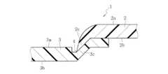
図1に示す樹脂成形品1は、自動車のインストルメントパネルであり、第1部分としての上面部2と、第2部分としての正面部3とを一体に有する。上面部2及び正面部3は、異なる樹脂材料で形成される。樹脂成形品1の意匠面(搭乗者から見える面)には、上面部2と正面部3との境界線(見切り線4)が設けられる。図2は、樹脂成形品1の見切り線4に垂直な断面であり、上面部2及び正面部3の図中上側の面が意匠面2a,3aである。上面部2及び正面部3の端部同士は重ね合わせられ、図示例では、上面部2の裏面側(図中下側)に正面部3が配される。上面部2と正面部3の重合部の両側において、上面部2の意匠面2aは正面部3の意匠面3aよりも図中上方に位置し、上面部2の裏面2bは正面部3の裏面3bよりも図中上方に位置している。 A resin molded
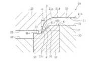
図3は、上記の樹脂成形品1を成形する射出成形金型10であり、上型20と、下型30と、スライド型40とを備える。図示例では、上型20が固定型であり、下型30が図中上下方向にスライドする可動型である。スライド型40は、下型30に対して図中上下方向にスライド可能とされる。 FIG. 3 shows an
上型20は、上面部2の意匠面2aを成形する第1成形面21と、正面部3の意匠面3aを成形する第2成形面22と、第1成形面21と第2成形面22との間に設けられた当接部23とを有する。第1成形面21の見切り線側(図中左側)の端部には、他の領域よりも曲率半径が小さい小円弧部21aが設けられる。本実施形態では、第1成形面21に、曲率半径が相対的に大きい大円弧部21bと、大円弧部21bの見切り線側に隣接して設けられ、曲率半径が相対的に小さい小円弧部21aと、小円弧部21aのさらに見切り線側に隣接して設けられた直線部21cとが設けられる。図示例では、大円弧部21bを平面(曲率0)で示している。大円弧部21bと小円弧部21a、及び小円弧部21aと直線部21cは、それぞれ滑らかに連続している。小円弧部21aと大円弧部21bとの境界には、変曲点21dが設けられる。直線部21cは、樹脂成形品1の離型を容易化するために、スライド型40のスライド方向(図中上下方向)に対して若干傾斜しており、その傾斜角αは例えば2°以上(図示例では5°)に設定される。第1成形面21の大円弧部21bは、第2成形面22よりも図中上方に位置している。当接部23は、第2成形面22よりも図中下方に突出している。 The
下型30は、上面部2の裏面2bを成形する第3成形面31と、正面部3の裏面3bを成形する第4成形面32と、第3成形面31と第4成形面32との間に設けられ、スライド型40を収容する孔33とを有する。第3成形面31は第4成形面32よりも図中上方に位置している。 The
スライド型40は、下型30の孔33の内部に配され、図中実線で示す上端位置と、図中鎖線で示す下端位置との間で上下方向にスライド可能とされる。スライド型40は、上面41に、平坦面41a,41bとこれらの間に設けられた傾斜面41cとを有する。図中左側の平坦面41aは、スライド型40を下端位置に配したときに、下型30の第4成形面32と連続する。図中右側の平坦面41bは、左側の平坦面41aよりも図中上側に配され、スライド型40を上端位置に配したときに、下型30の第3成形面31と連続する。スライド型40のスライド方向に対する傾斜面41cの傾斜角度βは、傾斜面41cで成形される正面部3の傾斜部3cの肉厚を確保するために、例えば30°以上(図示例では45°)に設定される。 The
以下、上記の射出成形金型10を用いた射出成形方法の手順を説明する。 Hereinafter, the procedure of the injection molding method using the
まず、図3に示すように、上型20と下型30を型締めした状態でスライド型40を上昇させて、スライド型40の上面41を上型20の当接部23に当接させる。これにより、上型20と下型30とで形成されるキャビティがスライド型40により区画され、上型20の第1成形面21、下型30の第3成形面31、及びスライド型40の上面41の平坦面41b及び傾斜面41cで囲まれた第1キャビティ50が形成される。 First, as shown in FIG. 3, the
第1キャビティ60の見切り線側(図中左側)の端部51は、先端へ向けて厚さを徐々に薄くした先細り形状を成している。図示例では、第1キャビティ60の端部51が、見切り線側へ向けて裏面側(図中下方)に変位した成形面の間、具体的には、上型20の第1成形面21の直線部21c及び小円弧部21aと、スライド型40の上面41の傾斜面41cとの間に形成される。第1キャビティ50の端部51の先端の角度θ(図示例では、直線部21cと傾斜面41cとの間の角度θ)が大きすぎると、端部51の肉厚が過剰となり、端部51に満たされた樹脂を早期に硬化させる効果(詳細は後述する)が得られないため、端部51の先端の角度θは60°以下、好ましくは45°以下とされる。また、端部51の先端の角度θが小さすぎると、端部51の肉厚が不足し、第2の樹脂材料の射出圧(詳細は後述する)で変形しやすくなるため、角度θは20°以上、好ましくは30°以上とされる。 The
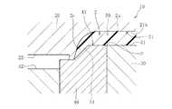
そして、図4に示すように、第1キャビティ50に第1の樹脂材料を射出し、上面部2を成形する。具体的には、第1キャビティ50に射出された第1の樹脂材料が、金型に接触して冷却されることにより硬化する。このとき、第1キャビティ50の端部51が先細り形状を成していることで、この端部51に満たされた第1の樹脂材料(すなわち、上面部2の端部2c)を、内部まで完全に早期に硬化させることができる。 Then, as shown in FIG. 4, the first resin material is injected into the
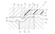
その後、図5に示すように、スライド型40を降下させて上型20から離反させ、第2キャビティ60を形成する。第2キャビティ60は、上型20の第2成形面22及び当接部23と、下型30の第4成形面32と、スライド型40の上面41と、上面部2の裏面2bとで囲まれている。このとき、スライド型40の降下は、(i)上面部2の端部2cが内部まで完全に硬化した後であって、且つ、(ii)上面部2のうち、第1キャビティ50におけるスライド型40の上面41と下型30の第3成形面31との境界P(図4参照)付近が完全に硬化する前のタイミングで行う。従来、上記(i)及び(ii)を両立させるタイミングを設定することは困難であったが、本発明では、上記のように第1キャビティ50の端部51を先細り形状とすることで、この部分に満たされた樹脂材料を早期に硬化させることができるため、上記(i)のタイミングを早期化することが許容され、これにより上記(i)及び(ii)を両立させるタイミングの設定が容易化される。尚、上記(ii)に示すように、上面部2の一部が完全に硬化していない状態でスライド型40を降下させることで、上面部2に加わる射出圧により、上面部2の裏面2bのうち、完全に硬化した端部51を除く領域が下方に若干膨らむ(図5に点線で誇張して示す)。 Thereafter, as shown in FIG. 5, the
そして、図6に示すように、第2キャビティ50に第2の樹脂材料を射出する。このとき、上面部2の端部2cは内部まで完全に硬化しているため、第2の樹脂材料の射出圧による変形が防止される。従って、上面部2の端部2cと上型20の第1成形面21(特に直線部21c)との間に第2の樹脂材料が入り込む事態が回避され、上面部2と正面部3との意匠面における境界線(見切り線4)の不明瞭化を防止できる。特に、本実施形態では、上面部2の端部2cが裏面側(図中下側)に曲がっていることで、第2の樹脂材料の射出圧による端部2cの変形を確実に防止し、端部2cと第1成形面21との間への第2の樹脂材料の侵入を確実に防止できる。また、上面部2のうち、スライド型40の上面41と下型30の第3成形面31との境界P付近は完全には硬化していないため、第2の樹脂材料の射出圧により上面部2の意匠面2a、特に境界Pの上方部分に白化が生じる事態を防止できる。その後、正面部3が硬化することで、上面部2と正面部3とを一体に有する樹脂成形品1が完成する。 Then, as shown in FIG. 6, the second resin material is injected into the
本発明は上記の実施形態に限られない。例えば、上記の実施形態では、図3に示すようにスライド型40を上型20に当接させて第1キャビティ50を形成した状態で、スライド型40の上面41と下型30の第3成形面31との境界Pが、第1成形面21の大円弧部21bの裏面側(すなわち、変曲点21dよりも図中右側)に配されているが、これに限られない。例えば図7に示す実施形態は、第1キャビティ50を形成した状態で、スライド型40の上面41と下型30の第3成形面31との境界Pが、第1成形面21の小円弧部21aの裏面側(すなわち、変曲点21dよりも図中左側)に配されている。このように、白化が生じやすい境界Pを、曲率半径の小さい小円弧部21aの下方に配することで、万が一この部分に白化が生じても、大円弧部21bに白化が生じた場合よりも白化を目立たなくすることができる。 The present invention is not limited to the above embodiment. For example, in the above embodiment, the third mold of the
1 樹脂成形品
2 上面部(第1部分)
2a 意匠面
3 正面部(第2部分)
3a 意匠面
4 見切り線
10 射出成形金型
20 上型(一方の金型)
21 第1成形面
21a 小円弧部
21b 大円弧部
21c 直線部
21d 変曲点
22 第2成形面
30 下型(他方の金型)
31 第3成形面
32 第4成形面
40 スライド型
50 第1キャビティ
60 第2キャビティ1 Resin molded
3a Design surface 4
21
31
Claims (2)
Translated fromJapanese前記スライド型を前記一方の金型に当接させて、前記一方の金型、前記他方の金型、及び前記スライド型で第1キャビティを形成し、該第1キャビティに第1の樹脂材料を射出して前記第1部分を成形する工程と、前記スライド型を前記一方の金型から離反させて、前記一方の金型、前記他方の金型、前記スライド型、及び前記第1部分で第2キャビティを形成し、該第2キャビティに第2の樹脂材料を射出して前記第2部分を成形する工程とを有し、
前記第1部分と前記第2部分の見切り線の延在方向と直交する断面において、前記第1キャビティの前記見切り線側の端部が、先端へ向けて厚さを徐々に薄くした先細り形状を成し、且つ、裏面側へ曲がっていることを特徴とする射出成形方法。By using an injection mold having one mold for molding the design surface, the other mold for molding the back surface, and a slide mold for defining a cavity formed by both molds, from different resin materials DoRi, a firstportion and a second portiondesign surface is respectively provided a method for molding a resin molded article having integral,
The slide mold is brought into contact with the one mold to form a first cavity with the one mold, the other mold, and the slide mold, and a first resin material is formed in the first cavity. A step of injecting and molding the first part; and separating the slide mold from the one mold, the first mold, the other mold, the slide mold, and the first part Forming two cavities, injecting a second resin material into the second cavities, and molding the second part,
In the cross section orthogonal to the extending direction of the parting line of the first part and the second part, the end part on the parting line side of the first cavity has a tapered shape in which the thickness is gradually reduced toward the tip. adultCity, and an injection molding method, characterized inthat bent to the back side.
前記第1部分と前記第2部分との見切り線の延在方向と直交する断面において、前記第1部分の前記見切り線側の端部が、先端へ向けて厚さを徐々に薄くした先細り形状を成し、且つ、裏面側へ曲がっていることを特徴とする樹脂成形品。After the first portion was injection-molded by injection molding a second portion in the same mold, Variesdepending Do a resinmaterial, said firstportion design surface is provided respectively to said second portion integrally A resin molded product having
In the cross section orthogonal to the extending direction of the parting line between the first part and the second part, the end part on the parting line side of the first part has a tapered shape in which the thickness is gradually reduced toward the tip. the formedto, and a resin molded article, characterized inthat bent to the back side.
Priority Applications (1)
| Application Number | Priority Date | Filing Date | Title |
|---|---|---|---|
| JP2013136721AJP6156985B2 (en) | 2013-06-28 | 2013-06-28 | Injection molding method and resin molded product |
Applications Claiming Priority (1)
| Application Number | Priority Date | Filing Date | Title |
|---|---|---|---|
| JP2013136721AJP6156985B2 (en) | 2013-06-28 | 2013-06-28 | Injection molding method and resin molded product |
Publications (2)
| Publication Number | Publication Date |
|---|---|
| JP2015009449A JP2015009449A (en) | 2015-01-19 |
| JP6156985B2true JP6156985B2 (en) | 2017-07-05 |
Family
ID=52303071
Family Applications (1)
| Application Number | Title | Priority Date | Filing Date |
|---|---|---|---|
| JP2013136721AActiveJP6156985B2 (en) | 2013-06-28 | 2013-06-28 | Injection molding method and resin molded product |
Country Status (1)
| Country | Link |
|---|---|
| JP (1) | JP6156985B2 (en) |
Families Citing this family (8)
| Publication number | Priority date | Publication date | Assignee | Title |
|---|---|---|---|---|
| JP6191583B2 (en)* | 2014-11-13 | 2017-09-06 | トヨタ自動車株式会社 | Resin panel structure for vehicles |
| JP6138863B2 (en)* | 2015-06-29 | 2017-05-31 | 本田技研工業株式会社 | Injection molding method and injection molding apparatus |
| CA3017296C (en)* | 2016-03-31 | 2020-06-02 | Honda Motor Co., Ltd. | Injection mold, injection molding method, and molded article |
| JP6920947B2 (en)* | 2017-09-28 | 2021-08-18 | ダイハツ工業株式会社 | Molding method for mold equipment and resin molded products |
| JP6959709B2 (en)* | 2017-09-28 | 2021-11-05 | ダイハツ工業株式会社 | Resin panel parts and their manufacturing methods |
| JP6920948B2 (en)* | 2017-09-28 | 2021-08-18 | ダイハツ工業株式会社 | Molding method for mold equipment and resin molded products |
| JP7151028B2 (en)* | 2018-09-25 | 2022-10-12 | ダイハツ工業株式会社 | Method for manufacturing resin molded member |
| JP7455636B2 (en)* | 2020-03-31 | 2024-03-26 | ダイハツ工業株式会社 | Multicolor molded product and method for manufacturing multicolor molded product |
Family Cites Families (2)
| Publication number | Priority date | Publication date | Assignee | Title |
|---|---|---|---|---|
| JPH10203287A (en)* | 1997-01-21 | 1998-08-04 | Toyota Motor Corp | Instrument panel integrated with airbag door and method of manufacturing the same |
| JPH11198178A (en)* | 1998-01-20 | 1999-07-27 | Fuji Photo Film Co Ltd | Multicolor molding of resin product |
- 2013
- 2013-06-28JPJP2013136721Apatent/JP6156985B2/enactiveActive
Also Published As
| Publication number | Publication date |
|---|---|
| JP2015009449A (en) | 2015-01-19 |
Similar Documents
| Publication | Publication Date | Title |
|---|---|---|
| JP6156985B2 (en) | Injection molding method and resin molded product | |
| JP5235470B2 (en) | Injection mold and injection molding method | |
| JP6910705B2 (en) | Manufacturing method of multi-layer member | |
| JP5422307B2 (en) | Two-color injection molding method for resin windows | |
| WO2009139307A1 (en) | Die for injection molding glass with frame | |
| CN102069563B (en) | The mould structure that local is Overmolded | |
| JP6776000B2 (en) | Manufacturing method of two-color molded products and two-color molded products | |
| JP6425908B2 (en) | Injection molding method, injection mold and molded article | |
| CN106080868A (en) | Inlay molded component and inlay the manufacture method of molded component | |
| JP7036720B2 (en) | Manufacturing method for molds and two-color molded products | |
| JP2005178185A (en) | Injection molding mold and method for producing injection-molded article using the mold | |
| JP6929000B2 (en) | Resin panel parts and their manufacturing methods | |
| JP6830982B2 (en) | Manufacturing method of two-color molded products | |
| JP5686695B2 (en) | Injection molding method and apparatus | |
| JP6400401B2 (en) | Mold for molding and molding method | |
| CN111497127B (en) | Method for molding a product having at least one corner, the product and a mold device | |
| JP6959709B2 (en) | Resin panel parts and their manufacturing methods | |
| JP2014166699A (en) | Injection molding die | |
| JP5414255B2 (en) | Cap injection molding method and cap | |
| JP6880395B2 (en) | Manufacturing method of injection molded product | |
| JP6647886B2 (en) | Mold | |
| JP2009298016A (en) | Molding method of resin molding | |
| CN105848511B (en) | Method for producing a housing shell for a seat belt buckle | |
| JP5409849B2 (en) | Skin integrated foam | |
| US20080299246A1 (en) | Multiple-shot injection mold assembly and a component having a retention rib made therewith |
Legal Events
| Date | Code | Title | Description |
|---|---|---|---|
| A621 | Written request for application examination | Free format text:JAPANESE INTERMEDIATE CODE: A621 Effective date:20160517 | |
| A977 | Report on retrieval | Free format text:JAPANESE INTERMEDIATE CODE: A971007 Effective date:20170309 | |
| A131 | Notification of reasons for refusal | Free format text:JAPANESE INTERMEDIATE CODE: A131 Effective date:20170315 | |
| A521 | Request for written amendment filed | Free format text:JAPANESE INTERMEDIATE CODE: A523 Effective date:20170515 | |
| TRDD | Decision of grant or rejection written | ||
| A01 | Written decision to grant a patent or to grant a registration (utility model) | Free format text:JAPANESE INTERMEDIATE CODE: A01 Effective date:20170605 | |
| A61 | First payment of annual fees (during grant procedure) | Free format text:JAPANESE INTERMEDIATE CODE: A61 Effective date:20170605 | |
| R150 | Certificate of patent or registration of utility model | Ref document number:6156985 Country of ref document:JP Free format text:JAPANESE INTERMEDIATE CODE: R150 | |
| R250 | Receipt of annual fees | Free format text:JAPANESE INTERMEDIATE CODE: R250 | |
| R250 | Receipt of annual fees | Free format text:JAPANESE INTERMEDIATE CODE: R250 | |
| R250 | Receipt of annual fees | Free format text:JAPANESE INTERMEDIATE CODE: R250 | |
| R250 | Receipt of annual fees | Free format text:JAPANESE INTERMEDIATE CODE: R250 | |
| R250 | Receipt of annual fees | Free format text:JAPANESE INTERMEDIATE CODE: R250 | |
| R250 | Receipt of annual fees | Free format text:JAPANESE INTERMEDIATE CODE: R250 |