JP6155559B2 - Vehicle drive device - Google Patents
Vehicle drive deviceDownload PDFInfo
- Publication number
- JP6155559B2 JP6155559B2JP2012128753AJP2012128753AJP6155559B2JP 6155559 B2JP6155559 B2JP 6155559B2JP 2012128753 AJP2012128753 AJP 2012128753AJP 2012128753 AJP2012128753 AJP 2012128753AJP 6155559 B2JP6155559 B2JP 6155559B2
- Authority
- JP
- Japan
- Prior art keywords
- motor generator
- engine
- torque assist
- torque
- vehicle
- Prior art date
- Legal status (The legal status is an assumption and is not a legal conclusion. Google has not performed a legal analysis and makes no representation as to the accuracy of the status listed.)
- Active
Links
Images


Classifications
- Y—GENERAL TAGGING OF NEW TECHNOLOGICAL DEVELOPMENTS; GENERAL TAGGING OF CROSS-SECTIONAL TECHNOLOGIES SPANNING OVER SEVERAL SECTIONS OF THE IPC; TECHNICAL SUBJECTS COVERED BY FORMER USPC CROSS-REFERENCE ART COLLECTIONS [XRACs] AND DIGESTS
- Y02—TECHNOLOGIES OR APPLICATIONS FOR MITIGATION OR ADAPTATION AGAINST CLIMATE CHANGE
- Y02T—CLIMATE CHANGE MITIGATION TECHNOLOGIES RELATED TO TRANSPORTATION
- Y02T10/00—Road transport of goods or passengers
- Y02T10/10—Internal combustion engine [ICE] based vehicles
- Y02T10/40—Engine management systems
- Y—GENERAL TAGGING OF NEW TECHNOLOGICAL DEVELOPMENTS; GENERAL TAGGING OF CROSS-SECTIONAL TECHNOLOGIES SPANNING OVER SEVERAL SECTIONS OF THE IPC; TECHNICAL SUBJECTS COVERED BY FORMER USPC CROSS-REFERENCE ART COLLECTIONS [XRACs] AND DIGESTS
- Y02—TECHNOLOGIES OR APPLICATIONS FOR MITIGATION OR ADAPTATION AGAINST CLIMATE CHANGE
- Y02T—CLIMATE CHANGE MITIGATION TECHNOLOGIES RELATED TO TRANSPORTATION
- Y02T10/00—Road transport of goods or passengers
- Y02T10/60—Other road transportation technologies with climate change mitigation effect
- Y02T10/62—Hybrid vehicles
Landscapes
- Combined Controls Of Internal Combustion Engines (AREA)
- Hybrid Electric Vehicles (AREA)
- Control Of Vehicle Engines Or Engines For Specific Uses (AREA)
Description
Translated fromJapaneseこの発明は車両の駆動装置に関する。 The present invention relates to a vehicle drive device.
エンジンのクランクシャフトに設けられたクランクプーリと、モータジェネレータに設けたモータジェネレータプーリとにベルトを巻き掛けてエンジンの始動を行うものにおいて、モータジェネレータは、オルタネータ機能(ジェネレータ機能)に加えて、エンジン始動のためのモータ機能を有するものがある(特許文献1参照)。 In the engine that starts the engine by winding a belt around the crank pulley provided on the crankshaft of the engine and the motor generator pulley provided on the motor generator, the motor generator has an engine function in addition to the alternator function (generator function). Some have a motor function for starting (see Patent Document 1).
また、このようなモータジェネレータを、エンジンの再始動時に駆動させて、エンジン出力のアシストを行うものがある(特許文献2参照)。 Also, there is a motor that assists engine output by driving such a motor generator when the engine is restarted (see Patent Document 2).
また、エンジンのアイドルストップを行う際に、バッテリのSOCが所定値以上の場合に、アイドルストップを許可するものがある(特許文献3参照)。 In addition, when performing engine idle stop, there is a technology that permits idle stop when the SOC of the battery is equal to or greater than a predetermined value (see Patent Document 3).
近年、燃費向上の観点から、車両停車中にエンジンを停止するアイドルストップ技術が普及している。 In recent years, from the viewpoint of improving fuel efficiency, idle stop technology for stopping the engine while the vehicle is stopped has become widespread.
また、従来技術のように、モータジェネレータを駆動してエンジンの駆動力をアシストすることにより、燃費を向上する技術も知られている。 In addition, as in the prior art, a technique for improving fuel efficiency by driving a motor generator to assist the driving force of an engine is also known.
このように、エンジンの駆動力をアシストするために、モータジェネレータを駆動するときには、バッテリに充電された電力が使用される。また、アイドルストップを終了してエンジンを始動するときにもモータジェネレータを駆動するので、バッテリの電力が使用される。 Thus, when the motor generator is driven in order to assist the driving force of the engine, the electric power charged in the battery is used. Further, since the motor generator is driven when the engine is started after the idle stop is finished, the battery power is used.
ところで、バッテリに蓄えられる電力の量には上限があるため、アイドリングストップとエンジン駆動力のアシストとを無制限に実行することはできない。ここで、従来技術では、アイドリングストップに必要なバッテリのSOCの下限値を設定している。しかし、アイドリングストップとエンジンのアシストとの両立が考慮されていないため、エンジンのアシストによりバッテリの電力が不足するとアイドルストップは行われず、燃費性能が向上しないという問題があった。 By the way, since there is an upper limit to the amount of electric power stored in the battery, idling stop and engine driving force assist cannot be executed without limitation. Here, in the prior art, a lower limit value of the SOC of the battery necessary for idling stop is set. However, since coexistence of idling stop and engine assist is not taken into account, there is a problem that idle stop is not performed when the battery power is insufficient due to engine assist, and fuel efficiency is not improved.
本発明は、このような問題点に鑑みてなされたものであり、エンジンのアイドルストップと、モータジェネレータによるエンジン駆動力のアシストとを両立させて、燃費性能を向上できる車両の駆動装置を提供することを目的とする。 The present invention has been made in view of such problems, and provides a vehicle drive device that can improve fuel efficiency by making both engine idle stop and engine drive force assist by a motor generator compatible. For the purpose.
本発明によると、車両を走行させる駆動力源と、駆動力源の出力軸に連結されたモータジェネレータと、モータジェネレータに電力を供給し、モータジェネレータにより発電された電力を充電するバッテリと、駆動力源の動作及びモータジェネレータの動作を制御する制御装置と、を備える車両の駆動装置に適用される。 According to the present invention, a driving force source for driving a vehicle, a motor generator coupled to an output shaft of the driving force source, a battery for supplying electric power to the motor generator and charging the electric power generated by the motor generator, and driving The present invention is applied to a vehicle drive device including a control device that controls the operation of a force source and the operation of a motor generator.
この車両の駆動装置において、制御装置は、車両の状態に基づき駆動力源を停止させ、駆動力要求があったときにモータジェネレータを回転させて駆動力源を再始動するアイドルストップ制御部と、車両の走行開始後にモータジェネレータを駆動して、駆動力源の駆動力をアシストするトルクアシスト制御部と、を備える。そして、制御装置は、制御装置は、車両の状態に基づき駆動力源を停止させ、駆動力要求があったときにモータジェネレータを回転させて駆動力源を再始動するアイドルストップ制御部と、車両の走行開始後にモータジェネレータを駆動して、駆動力源の駆動力をアシストするトルクアシスト制御部と、を備え、バッテリの状態に基づいて、アイドルストップ制御部の動作を実行し、トルクアシスト制御部の動作を制限する、すなわち、バッテリの充電量が、第1の所定容量よりも大きい場合にアイドルストップ制御部の動作を実行し、バッテリの充電量が、第1の所定容量よりも大きい第2の所定容量よりも大きい場合にトルクアシスト制御部の動作を実行し、トルクアシスト制御部は、車両の走行開始後にモータジェネレータを駆動し、モータジェネレータの駆動時間を、第1の所定容量と第2の所定容量との差分のバッテリ容量に基づいた時間である所定時間内に制限することを特徴とする。In this vehicle driving device, the control device stops the driving force source based on the state of the vehicle, and when there is a driving force request, an idle stop control unit that rotates the motor generator to restart the driving force source; A torque assist control unit that drives the motor generator after the vehicle starts running and assists the driving force of the driving force source. Then, the control devicestops the driving force source based on the state of the vehicle, rotates the motor generator when the driving force is requested, and restarts the driving force source, the vehicle A torque assist control unit that drives the motor generator after the start of driving and assists the driving force of the driving force source, and executes the operation of the idle stop control unit based on the state of the battery, and the torque assist control unit The operation of the idle stop control unit is executed when the amount of charge of the battery is larger than the first predetermined capacity, and the second amount of charge of the battery is larger than the first predetermined capacity. The torque assist control unit performs the operation of the torque assist control unit when the vehicle is larger than the predetermined capacity, and the torque assist control unit drives the motor generator after the vehicle starts running, The driving time over motor generator, andlimits the first predetermined volume and a predetermined time is a time based on the battery capacity of the difference between the second predetermined capacity.
本発明によれば、駆動力源を停止するアイドルストップをモータジェネレータによるトルクアシストの動作よりも優先させるので、駆動力源の燃料の消費を抑えることができて、燃費性能を向上することができる。 According to the present invention, since the idling stop for stopping the driving force source is prioritized over the torque assist operation by the motor generator, the consumption of fuel from the driving force source can be suppressed, and the fuel efficiency can be improved. .
以下、本発明の実施形態を、図面を参照して説明する。 Embodiments of the present invention will be described below with reference to the drawings.
図1は、本発明の実施形態の車両1の駆動装置の構成を示す説明図である。 FIG. 1 is an explanatory diagram showing a configuration of a drive device for a
車両1は、エンジン2、モータジェネレータ21、エアコン用コンプレッサ31を有する。 The
エンジン2のクランク軸3、モータジェネレータ21の回転軸22、エアコン用コンプレッサ31の回転軸32が平行に配置されている。クランク軸3の一端にクランクプーリ4が、回転軸22、32にそれぞれプーリ23、33が備えられている。これらクランクプーリ4、プーリ23、33にはベルト5が掛け回され、クランク軸3、回転軸22、33の間はベルト5によって動力が伝達(伝導)される。 The crankshaft 3 of the
エンジン2には、エンジンの始動に用いるスタータ6が備えられている。エンジン2のクランク軸3の他端にはトルクコンバータ8を介してベルト式の自動変速機9が接続されている。 The
トルクコンバータ8は図示しないポンプインペラ、タービンランナを有する。ベルト式の自動変速機9は図示しないプライマリプーリ、セカンダリプーリ、これらプーリに掛け回されるスチールベルトを有する。エンジン2の回転駆動力はこれらトルクコンバータ8、自動変速機9を介して最終的に車両駆動輪(図示しない)に伝達される。 The
車両1には、電源としてメインバッテリ41とサブバッテリ42との二つのバッテリが備えられる。メインバッテリ41とサブバッテリ42とは、いずれも14Vの電圧を入出力するバッテリである。メインバッテリ41とサブバッテリ42とは、並列された2つのリレー43によって電気的に接続されている。 The
スタータ6及びモータジェネレータ21は、メインバッテリ41に電気的に接続され、メインバッテリ41から電力が供給される。モータジェネレータ21は交流電機により構成されており、このモータジェネレータ21にはメインバッテリ41との間で直流と交流とを変換するインバータ24が備えられている。 The starter 6 and the
エンジンコントロールモジュール(ECM)51は、エンジン2、スタータ6及びモータジェネレータ21の動作を制御する制御装置として機能する。 The engine control module (ECM) 51 functions as a control device that controls operations of the
ここで、エンジン2の構成を、図2を参照して説明する。 Here, the configuration of the
図2は、本発明の実施形態のガソリンエンジンであるエンジン2の制御システムの構成図である。 FIG. 2 is a configuration diagram of a control system of the
各吸気ポート(図示しない)には燃料噴射弁7が設けられている。燃料噴射弁7は、エンジン2に燃料を間欠的に供給するものであり、ここでは4気筒分が例示されている。 Each intake port (not shown) is provided with a
吸気通路11は電子制御のスロットル弁12を備える。スロットル弁12はスロットルモータ13によって開度(以下、「スロットル開度」という。)が制御される。スロットル弁12の実際のスロットル開度はスロットルセンサ14により検出され、ECM51に入力される。 The
ECM51には、アクセルセンサ53からのアクセル開度(アクセルペダル52の踏込量)の信号、クランク角センサ54からのクランク角の信号、エアフローメータ55からの吸入空気量の信号が入力される。 The
ECM51は、クランク角センサ54の信号からエンジン2の回転速度(エンジン回転速度Ne)を算出し、また、その他の信号に基づいて目標吸入空気量及び目標燃料噴射量を算出する。そして、これら目標吸入空気量及び目標燃料噴射量が得られるようにスロットルモータ13及び各燃料噴射弁7に指令を出す。 The ECM 51 calculates the rotational speed (engine rotational speed Ne) of the
エンジン2は、燃焼室(シリンダ)に臨んで点火プラグを備えている。ECM51は、圧縮上死点前の所定の時期に点火コイルの一次側電流を遮断することにより点火プラグに火花を発生させ、これによって燃焼室内の混合気に点火する。 The
また、ECM51は、スタータスイッチ56からの信号に基づいて初回の始動要求があると判断したときに、スタータ6を駆動しエンジン2を始動させる。 Further, when the
また、ECM51は、燃費向上を目的としてアイドルストップ制御を行う。 Further, the ECM 51 performs idle stop control for the purpose of improving fuel consumption.
たとえば、アクセルペダル52が踏み込まれておらず(APO=0)、ブレーキペダル57が踏み込まれ(ブレーキスイッチ58がON)、かつ車両1が停止状態にある(車速VSP=0)のときにアイドルストップ許可条件が成立する。 For example, when the
アイドルストップ許可条件が成立したときには、ECM51は、燃料噴射弁7から吸気ポートへの燃料噴射を遮断してエンジン2を停止する。これによって無駄な燃料消費を低減する。 When the idle stop permission condition is satisfied, the ECM 51 shuts off the fuel injection from the
その後、アイドルストップ状態で、アクセルペダル52の踏み込みや、ブレーキペダル57の戻し(ブレーキスイッチ58がOFF)など、運転者からの駆動要求があった場合は、アイドルストップ許可条件が不成立となる。このとき、ECM51は、モータジェネレータ21をスタータとして用いてエンジン2をクランキングし、燃料噴射弁7からの燃料噴射と点火プラグによる火花点火とを再開しエンジン2を再始動する。 Thereafter, when there is a drive request from the driver such as depression of the
このように、モータジェネレータ21をアイドルストップからのエンジン2の始動用として用いることにより、スタータ6の使用頻度を減らしてスタータ6を保護する。このように、ECM51がエンジン2を停止させ、モータジェネレータ21を動作させてエンジン2を再始動させるように動作させることにより、アイドルストップ制御部が構成される。 Thus, by using the
なお、スタータ6やモータジェネレータ21を駆動するときには、ECM51により2つのリレー33をともに遮断して、メインバッテリ41とサブバッテリ42を電気的に切り離す。これによって、スタータ6やモータジェネレータ21がメインバッテリ41のみの電力で駆動し、サブバッテリ42の電圧が変動することを防止する。 Note that when the starter 6 and the
図1に戻り、車両1は自動変速機用コントロールユニット(CVTCU)61を備える。 Returning to FIG. 1, the
CVTCU61は、車速とスロットル開度とから定まる車両の走行条件に応じて、自動変速機9の変速比を無段階に制御する。 The
また、ポンプインペラ、タービンランナを有するトルクコンバータ8には、ポンプインペラとタービンランナとを締結・開放する機械式のロックアップクラッチを備えている。ロックアップクラッチを締結する車両の走行域はロックアップ領域(車速とスロットル開度とをパラメータとしている)として予め定めている。CVTCU61では車両の走行条件がロックアップ領域となったとき、ロックアップクラッチを締結してエンジン2と自動変速機9とを直結状態とし、車両の走行条件がロックアップ領域とないときにはロックアップクラッチを開放する。エンジン2と自動変速機9とを直結状態としたときにはトルクコンバータ8でのトルクの吸収がなくなり、その分燃費が良くなる。 The
車両1は、また、ビークルダイナミックコントロールユニット(VDCCU)62、車速感応式電動パワーステアリング用コントロールユニット(EPSCU)63、エアコン用オートアンプ64、コンビネーションメータ66を備える。 The
VDCCU62はセンサを備え、車両1が横滑りや尻振りを起こしそうになったことを検知する。この横滑り状態に応じて、ブレーキ制御とエンジン出力制御により走行時の車両安定性を向上させる。 The
EPSCU63は、トルクセンサからの操舵トルク及び車速から最適なアシストトルク信号をEPSモータに出力して、操舵力をアシストする。 The
これらCVTCU61、VDCCU62、EPSCU63及びコンビネーションメータ66は、電圧降下を許容できない電気負荷である。これらは、メインバッテリ41と電気的に切り離し可能なサブバッテリ42から電力の供給を受ける。 The
ECM51、CVTCU61、VDCCU62、EPSCU63、エアコン用オートアンプ64及びコンビネーションメータ66の間はCAN(Controller Area Network)により接続される。 The
次に、モータジェネレータ21によるエンジン駆動力のアシストについて説明する。 Next, engine driving force assist by the
前述のように、アイドルストップによりエンジン2を停止した後、アイドルストップ許可条件が成立しなくなったときは、ECM51は、メインバッテリ41を電源として用いてモータジェネレータ21を駆動して、エンジン2を再始動する。 As described above, after the
エンジン2が再始動し、車両1が走行を開始した後に、エンジン回転速度Neが予め定めた所定の回転速度域にある場合に、モータジェネレータ21を用いたトルクアシストが許可される。トルクアシストの許可中にエンジン回転速度Neが所定の回転速度域を外れたときには、トルクアシストが禁止される。 After the
トルクアシストを許可するときには、ECM51は、エンジン2をトルクアシストするよう、メインバッテリ41を電源として用いてモータジェネレータ21に所定のアシストトルクを発生させる。また、トルクアシストを禁止するときには、モータジェネレータ21の駆動を停止してアシストトルクを発生させない。これによって、エンジン2の再始動後かつ車両1の走行開始後に良好な加速応答性(運転性)が得られるようにする。 When permitting torque assist, the
また、メインバッテリ41には、電流センサ49が備えられており、ECM51は、メインバッテリ41の充放電電流値を検出する。ECM51は、メインバッテリ41の充放電電流値に基づいて積算処理を行い、メインバッテリ41のSOC(State Of Charge)を算出する。このSOCに基づいてメインバッテリ41の充放電の収支を管理する。 The
インバータ24とECM51とは、LIN(Local Interconnect Network)で接続している。このLINを介してECM51がインバータ24に対して、モータジェネレータ21を駆動するのか、それともモータジェネレータ21で発電させるのか、モータとして駆動するためにどのくらいの電流を流すのか等を指令する。 The
エンジン2及びモータジェネレータ21には回転振動の共振点が存在する。この回転振動の共振点は、エンジン回転速度Neが例えば1000rpmより低い回転速度域に存在する。ベルト5の張力が低い状態でトルクアシストを実行すると、エンジン2およびモータジェネレータ21の回転振動の共振により(共振回転速度域で)ベルト滑りが発生し、ベルト5に鳴きが発生してしまう虞がある。 The
一方、この共振によるベルト滑りを防止するためにベルト5の張力を高くすると、クランクプーリ4とベルト5との間でのフリクションが増大してしまい燃費悪化を招く。クランクプーリ4とベルト5との間でのフリクション増大による燃費悪化を避けるために、ベルト張力を高めに設定することはできない。 On the other hand, if the tension of the
従って、共振によるベルト滑り防止を考え、エンジン回転速度Neが、例えば1000rpm(第1閾値)より高い回転速度域(モータジェネレータ回転速度が例えば2600rpmより高い中・高回転速度域)でのみトルクアシストを許可する。エンジン回転速度Neが、例えば1000rpm(第1閾値)以下の回転速度域(モータジェネレータ回転速度が、例えば2600rpm以下の低回転速度域)ではトルクアシストを禁止する。 Therefore, in consideration of preventing belt slippage due to resonance, torque assist is performed only in a rotational speed range where the engine rotational speed Ne is higher than, for example, 1000 rpm (first threshold) (medium / high rotational speed range where the motor generator rotational speed is higher than 2600 rpm, for example). To give permission. Torque assist is prohibited when the engine rotational speed Ne is, for example, 1000 rpm (first threshold) or less (a motor generator rotational speed is, for example, a low rotational speed range of 2600 rpm or less).
エンジン2が再始動し、車両1が走行を開始した後に、エンジン回転速度Neが第1閾値を超えた場合に、モータジェネレータ21を駆動してトルクアシストを行う。このように、車両1の走行開始後にモータジェネレータ21を駆動してエンジン2の駆動力をアシストするように制御することにより、トルクアシスト制御部が構成される。 After the
図3は、本発明の実施形態のエンジン再始動の開始からのタイミングチャートを示す。 FIG. 3 shows a timing chart from the start of engine restart according to the embodiment of the present invention.
図3は、エンジン回転速度Ne、車両トルク、車速VSP、アクセル開度AOPそれぞれの時間の変化を示す。なお、図3に示す「トルクアシスト許可フラグ」、「トルクアシスト実行フラグ」については、図4で説明する。 FIG. 3 shows changes in time of the engine rotation speed Ne, vehicle torque, vehicle speed VSP, and accelerator opening AOP. The “torque assist permission flag” and the “torque assist execution flag” shown in FIG. 3 will be described with reference to FIG.
「車両トルク」とは、車両の駆動に用いられるトルクのことで、通常はエンジントルクである。モータジェネレータ21によるトルクアシストがあるときには、このアシストトルクとエンジントルクの合計が車両トルクとなる。 “Vehicle torque” refers to torque used for driving a vehicle, and is usually engine torque. When there is torque assist by the
タイミングt1において、アイドルストップ許可条件が不成立となった場合は、ECM51は、モータジェネレータ21を駆動してエンジン2のクランキングを行うと共に、燃料噴射弁7からの燃料噴射及び点火プラグによる火花点火を再開する。これによりエンジン2が燃焼を開始してエンジン2が再始動する。ECM51は、エンジン回転速度Neが所定の完爆回転速度となったときに、エンジン2が再始動したと判定する(タイミングt2)。 If the idle stop permission condition is not satisfied at timing t1, the
ここで、タイミングt2の付近でドライバがアクセルペダル52を少し踏み込んだため、エンジン回転速度Neが上昇して、車両トルクが増加する。これにより、車両1が走行を開始する(タイミングt3)。 Here, since the driver slightly depresses the
図3において、車両1を発進させた後もアクセル開度APOが略一定であるので、エンジン回転速度Neと車両トルクとは、タイミングt3を過ぎた当たりで略一定値となっている。 In FIG. 3, since the accelerator opening APO is substantially constant even after the
次に、タイミングt5でドライバがアクセルペダル52を大きく踏み込んだとする。このアクセル開度の増加に応じてエンジン回転速度Neが上昇する。 Next, it is assumed that the driver greatly depresses the
このとき、エンジン回転速度Neが第1閾値(RPMLOK)を超えたとき、ECM51は、モータジェネレータ21が低回転速度域を脱したと判断する。ECM51は、メインバッテリ41からインバータ24に電流を供給してモータジェネレータ21をモータとして駆動する(タイミングt6)。 At this time, when the engine rotation speed Ne exceeds the first threshold value (RPMLK), the
このタイミングt6以降、エンジントルクにモータトルクが加わり、車両トルクが増大し、車速が増大する。この結果、ドライバの望む加速が直ぐに得られることとなる。なお、モータジェネレータ21が発生するトルクは、ゼロから漸増して最大トルクとなるようにする。 After this timing t6, motor torque is added to engine torque, vehicle torque increases, and vehicle speed increases. As a result, the acceleration desired by the driver can be obtained immediately. The torque generated by the
このような制御によって、車両発信時のトルクアシストが実行される。 By such control, torque assist at the time of vehicle transmission is executed.
モータジェネレータ21によるトルクアシスト分をエンジン2の発生するトルクで賄おうとすると、燃料噴射弁7からの燃料供給を増量補正しなければならず、それだけ燃料消費が多くなり、燃費が悪くなる。これに対して、車両1の減速時にモータジェネレータ21により運動エネルギーを電気エネルギーとして回生し、メインバッテリ41に蓄えておく。そして、エンジン回転速度Neが第1閾値RPMLOKを超えたときに、メインバッテリ41の電気エネルギーによりモータジェネレータ21にアシストトルクを発生させるのであれば、燃料を消費することがないので、燃費を悪くすることがない。 If an attempt is made to cover the torque assist generated by the
また、モータジェネレータ21はエンジン2よりも応答良くトルクを発生することができるので、ドライバがアクセルペダルを踏み込み過ぎることを避け、無駄な燃料を消費することがない。 Further, since the
次に、ECM51で行われるトルクアシストを、図4のフローチャートを参照して説明する。 Next, torque assist performed by the
図4は、本発明の実施形態のトルクアシストのフローチャートである。 FIG. 4 is a flowchart of torque assist according to the embodiment of the present invention.
この図4に示すフローチャートは、ECM51により、所定周期(例えば10ms毎)に実行される。 The flowchart shown in FIG. 4 is executed by the
まず、ECM51は、ステップS1において、エンジン2の初回始動後であるか否かを判定する。エンジン2の初回始動である場合は、スタータ6を用いてエンジンが始動されるので、NOが選択されて本フローチャートによる処理を終了する。 First, the
エンジン2の初回始動後である場合は、ステップS2に進み、ECM51は、エンジン2の再始動後であるか否かを判定する。 If it is after the initial start of the
エンジン2の再始動とは、アイドルストップからのエンジン2の再始動のことである。アイドルストップからエンジン2を再始動する場合はモータジェネレータ21によって行われるので、ECM51は、車両停止中にモータジェネレータ21が作動したときにアイドルストップからのエンジン始動が行われたと判断する。アイドルストップからのエンジン2の再始動が行われていなければ、本フローチャートによる処理を終了する。 The restart of the
アイドルストップからのエンジン2の再始動が行われた後であれば、ステップS3に移行する。 If the
ステップS3では、車両1の走行中であるか否かを判定する。車速がゼロまたはゼロに近い値以下であるときには車両の停止中(走行中でない)と判断し、本フローチャートの処理を終了する。 In step S3, it is determined whether or not the
車速がゼロでないときまたはゼロに近い値を超えていると判断した場合は、車両の走行中であると判断してステップS4に進む。 If it is determined that the vehicle speed is not zero or exceeds a value close to zero, it is determined that the vehicle is traveling and the process proceeds to step S4.
ステップS4では、ECM51は、トルクアシスト許可条件が成立しているか否かを判断する。 In step S4, the
トルクアシスト許可条件の成立は、次の(1)及び(2)の条件が成立してないときにトルクアシスト許可条件が成立したと判断する。言い換えると、次の(1)及び(2)のいずれか一つの条件が成立したときには、トルクアシスト許可条件が成立しない。
(1)ロックアップクラッチが解放されているとき。
(2)メインバッテリ41のSOCがトルクアシスト許可閾値未満であるとき。When the torque assist permission condition is satisfied, it is determined that the torque assist permission condition is satisfied when the following conditions (1) and (2) are not satisfied. In other words, when any one of the following conditions (1) and (2) is satisfied, the torque assist permission condition is not satisfied.
(1) When the lockup clutch is released.
(2) When the SOC of the
ロックアップクラッチが解放されているときにエンジン2にアシストトルクを加えても、アシストトルクの一部がトルクコンバータ8で吸収されてしまい、トルク伝達の効率が悪いため、トルクアシストは禁止する。ロックアップクラッチを締結しエンジン2と自動変速機9とを直結状態としているときにエンジン2に対してアシストトルクを加えるのであれば、アシストトルクの分が車両トルクの増加となるので、トルク伝達の効率が悪くなることがない。なお、ロックアップクラッチの締結又は解放は、前述のように車速とスロットル開度とに基づいて決定される。 Even if an assist torque is applied to the
また、メインバッテリ41のSOCが十分に大きく、トルクアシスト許可閾値値以上であるときには、ECM51は、トルクアシストを許可する。 Further, when the SOC of the
この条件(1)及び(2)のいずれも成立していない場合は、トルクアシスト許可条件が成立したと判断して、ステップS5に進む。ステップS5では、ECM51は、トルクアシスト許可フラグ=1に設定する。 If neither of the conditions (1) and (2) is satisfied, it is determined that the torque assist permission condition is satisfied, and the process proceeds to step S5. In step S5, the
図3において、t4のタイミングで、トルクアシスト許可フラグがゼロから1へと切り換わっていることが示されている。 FIG. 3 shows that the torque assist permission flag is switched from zero to 1 at the timing of t4.
一方、この条件(1)及び(2)の少なくとも一方が成立した場合は、トルクアシスト許可条件が成立しないと判断して、ステップS6に進む。ステップS6では、ECM51は、トルクアシスト許可フラグ=0に設定する。 On the other hand, if at least one of the conditions (1) and (2) is satisfied, it is determined that the torque assist permission condition is not satisfied, and the process proceeds to step S6. In step S6, the
次に、ステップS7では、トルクアシスト許可フラグが1であるかを判定する。トルクアシスト許可フラグ=1であるときにはステップ8に進む。 Next, in step S7, it is determined whether the torque assist permission flag is 1. When the torque assist permission flag = 1, the routine proceeds to step 8.
ステップS8では、ECM51は、エンジン回転速度Ne[rpm]と第1閾値RPMLOK[rpm]を比較する。第1閾値RPMLOKはモータジェネレータ21の低回転速度域の上限として予め定められている値である。 In step S8, the
エンジン回転速度Neが第1閾値RPMLOKを超えている場合は、ECM51は、モータジェネレータ21の低回転速度域を外れたと判断する。このときにはトルクアシストを実行するためにステップS9に進む。ステップS9では、ECM51は、トルクアシスト実行フラグ=1に設定する。 When the engine rotational speed Ne exceeds the first threshold value RPMLOK, the
トルクアシスト実行フラグ=1に設定されることにより、ECM51は、インバータ24に電流を供給してモータジェネレータ21をモータとして駆動する。 By setting the torque assist execution flag = 1, the
図3において、タイミングt6でトルクアシスト実行フラグがゼロから1へと切り換わっていることが示されている。これにより、モータトルクがエンジントルクに加わる。 FIG. 3 shows that the torque assist execution flag switches from zero to 1 at timing t6. Thereby, motor torque is added to engine torque.
なお、このとき、モータジェネレータ21が発生するトルクをゼロから漸増させて最大トルクとなるように、ECM51は、インバータ24に流す電流値を制御する。これは、車両発進時のように、運転ショックを感じやすいエンジン2の低回転速度域でモータジェネレータ21がステップ的に最大トルクを発生するのでは運転ショックが生じてしまうためである。また、トルクアシストを終了する場合も、最大トルクから漸増してゼロとなるように、インバータ24に流す電流値を制御する。 At this time, the
また、トルクアシストを行わせる期間(インバータ24に電流を流す期間)は後述するように、予め定めた時間とする。トルクアシストを行わせる期間を長くすればそれだけメインバッテリ41の電力消費を早めるので、メインバッテリ41の電力消費に影響を与えることがないように時間を設定しておく。 Further, a period during which torque assist is performed (period in which current is passed through the inverter 24) is set to a predetermined time, as will be described later. Since the power consumption of the
ステップS8でエンジン回転速度Neが第1閾値RPMLOK以下であると判断した場合は、モータジェネレータ21が低回転速度域にあると判断して、ステップS10に進む。ステップS10では、ECM51は、トルクアシスト実行フラグ=0に設定する。 If it is determined in step S8 that the engine rotational speed Ne is equal to or lower than the first threshold value RPMLOK, it is determined that the
トルクアシスト実行フラグ=0に設定することにより、ECM51は、インバータ24への電流供給を遮断してモータジェネレータ21を非駆動状態とする。 By setting the torque assist execution flag = 0, the
言い換えると、車両走行中での加速によってドライバが望みの加速が得られたとしてアクセルペダル52を戻すことによりエンジン回転速度Neが第1閾値RPMLOK以下となった場合は、もはやトルクアシストは必要ないので、トルクアシスト実行フラグ=0と設定して、モータジェネレータ21のトルクアシストを禁止する。 In other words, if the driver has obtained the desired acceleration due to acceleration while the vehicle is running, and the engine speed Ne falls below the first threshold RPMLOK by returning the
これにより、モータジェネレータ21の低回転速度域におけるベルト5の鳴きを防止し、クランク軸3、回転軸22、32の強度を確保しつつ、燃費向上と良好な加速応答性(運転性)を両立できる。 As a result, the squealing of the
なお、ステップS7でトルクアシスト許可条件が成立しない場合には、ステップS10に進み、トルクアシスト実行フラグ=0に設定する。 If the torque assist permission condition is not satisfied in step S7, the process proceeds to step S10, where the torque assist execution flag = 0 is set.
このような制御により、車両発進時のトルクアシストが実行される。 By such control, torque assist when the vehicle starts is executed.
次に、本発明の実施形態のトルクアシストの許可について説明する。 Next, torque assist permission according to the embodiment of the present invention will be described.
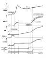
図5は、本発明の実施形態のメインバッテリ41のSOCとトルクアシスト許可との関係を示すタイムチャートである。 FIG. 5 is a time chart showing the relationship between the SOC of the
図5において、縦軸にバッテリの充電積算量(SOC)を示し、横軸は時間を示す。また、実線は本発明の実施形態を適用した場合のトルクアシストの許可とSOCとの関係を示し、一点鎖線は、本発明の実施形態を適用しない場合のトルクアシストの許可とSOCとの関係を示す。 In FIG. 5, the vertical axis represents the accumulated charge amount (SOC) of the battery, and the horizontal axis represents time. Further, the solid line shows the relationship between the torque assist permission and the SOC when the embodiment of the present invention is applied, and the alternate long and short dash line shows the relationship between the torque assist permission and the SOC when the embodiment of the present invention is not applied. Show.
なお、図5におけるSOC2は、アイドルストップ条件解除後、モータジェネレータ21を駆動してエンジン2を始動するために必要なSOCの閾値である。また、SOC1は、後述するように、トルクアシストを許可する条件となるSOCの閾値であり、SOC2よりも大きな値に設定される。 Note that SOC2 in FIG. 5 is a threshold value of SOC necessary for driving the
SOC2未満の領域を第3領域、SOC2以上でありSOC1未満である領域を第2領域、SOC1以上の領域を第1領域とする。 A region less than SOC2 is a third region, a region greater than or equal to SOC2 and less than SOC1 is a second region, and a region greater than SOC1 is a first region.
エンジン2が始動され車両1が走行を開始した後は、エンジン2の回生動力によりメインバッテリ41が充電され、また電気負荷44が使用されることにより、メインバッテリ41の電力が消費される。 After the
ここで、前述の条件(2)のように、メインバッテリ41のSOCがトルクアシスト許可閾値未満であるときという条件が成立していない場合は、トルクアシストを許可する。このトルクアシスト許可閾値を、図5におけるSOC2に設定した場合を考える。 Here, as in the condition (2) described above, when the condition that the SOC of the
タイミングt11において前述の条件(1)が成立しない場合に、条件(2)、すなわち、SOCが、トルクアシスト許可閾値であるSOC2以上である場合は、トルクアシストが許可される。これによりモータジェネレータ21が駆動してトルクアシストを行う(図5中○で示す)。モータジェネレータ21の駆動によりメインバッテリ41の電力が消費され、SOCが一点鎖線で示すように降下する。 When the above condition (1) is not satisfied at the timing t11, if the condition (2), that is, the SOC is equal to or higher than the SOC2 that is the torque assist permission threshold, torque assist is permitted. As a result, the
さらにタイミングt12でも同様に、条件(1)及び(2)のいずれも成立せず、トルクアシストが許可される。モータジェネレータ21の駆動によりさらにメインバッテリ41の電力が消費され、SOCが一点鎖線で示すように降下する。 Furthermore, similarly at timing t12, neither of the conditions (1) and (2) is satisfied, and torque assist is permitted. The electric power of the
さらにタイミングt14でも同様に、条件(1)及び(2)のいずれも成立せず、トルクアシストが許可される。モータジェネレータ21の駆動によりさらにメインバッテリ41の電力が消費され、SOCが一点鎖線で示すように降下する。 Furthermore, similarly at timing t14, neither of the conditions (1) and (2) is satisfied, and torque assist is permitted. The electric power of the
結果として、タイミングt14において、メインバッテリのSOCがSOC2未満となる。以降は、メインバッテリ41がSOC2以上となるまで十分に充電されるまでは、トルクアシストが実行されないこととなる。 As a result, at the timing t14, the SOC of the main battery becomes less than SOC2. Thereafter, the torque assist is not executed until the
これに対して本願発明では、前述の条件(2)の、メインバッテリ41のSOCがトルクアシスト許可閾値未満であるときという条件において、このトルクアシスト許可閾値を、SOC2よりも大きい値であるSOC1に設定する。 On the other hand, in the present invention, the torque assist permission threshold is set to SOC1 that is larger than SOC2 under the condition (2) in which the SOC of the
このように設定した場合は、タイミングt11において前述の条件(1)が成立しない場合に、条件(2)、すなわち、SOCが、トルクアシスト許可閾値であるSOC1未満であるので、タイミングt11におけるトルクアシストは禁止される。 In this case, when the above-described condition (1) is not satisfied at timing t11, the condition (2), that is, the SOC is less than the SOC1 that is the torque assist permission threshold value. Is forbidden.
この後、エンジンの回生動力によりメインバッテリ41が充電されて、SOCが実線で示すようにやがて上昇する。 Thereafter, the
その後、タイミングt12において前述の条件(1)が成立しない場合に、条件(2)成立しない、すなわち、SOCがトルクアシスト許可閾値であるSOC1以上である場合は、トルクアシストが許可される。これによりモータジェネレータ21が駆動してトルクアシストを行う(図5中□で示す)。モータジェネレータ21の駆動によりメインバッテリ41の電力が消費され、SOCが実線で示すように降下する。 Thereafter, when the condition (1) is not satisfied at the timing t12, the condition (2) is not satisfied, that is, if the SOC is equal to or greater than the SOC1 that is the torque assist permission threshold, torque assist is permitted. As a result, the
その後、タイミングt13において、条件(1)が成立せず、条件(2)が成立しない、すなわち、SOCがトルクアシスト許可閾値であるSOC1以上である場合は、トルクアシストが許可される。モータジェネレータ21の駆動によりメインバッテリ41の電力が消費され、SOCが実線で示すように降下する。 Thereafter, at timing t13, if the condition (1) is not satisfied and the condition (2) is not satisfied, that is, if the SOC is equal to or greater than SOC1 that is a torque assist permission threshold, torque assist is permitted. The power of the
図5において、一点鎖線で示すSOCの推移と実線で示すSOCの推移とを比較した場合に、実線で示したSOCの推移のほうが、より長時間SOC2以上である領域を保っている(タイミングt14からt15の間)。メインバッテリ41のSOCがSOC2以上である場合は、アイドルストップが可能である領域である。実線で示した本願発明の制御により、より長時間アイドルストップを行うことが可能となり、アイドルストップにより燃料消費量が抑制されて燃費性能を向上することができる。 In FIG. 5, when the SOC transition indicated by the alternate long and short dash line is compared with the SOC transition indicated by the solid line, the SOC transition indicated by the solid line maintains a region where the SOC2 is longer than the time (timing t14). To t15). When the SOC of the
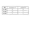
この図5の制御を要約すると、図6に示す説明図のようになる。メインバッテリ41のSOCが領域3にある場合は、アイドルストップ及びトルクアシストはいずれも許可されない。また、メインバッテリ41のSOCがSOC1以上でSOC2未満の領域2にある場合は、アイドルストップのみが許可され、トルクアシストは許可されない。また、メインバッテリ41のSOCがSOC2以上の領域1にある場合は、アイドルストップ及びトルクアシストのいずれもが許可される。 The control of FIG. 5 is summarized as an explanatory diagram shown in FIG. When the SOC of the
このような制御によって、メインバッテリ41のSOCに基づいて、アイドルストップの許可とトルクアシストの許可とを決定する。より詳しくは、アイドルストップは燃料を消費しないために燃費性能の向上が加速時のトルクアシストよりも大きい。従って、アイドルストップを優先して実行することにより、燃費性能を向上することができる。 By such control, permission of idling stop and permission of torque assist are determined based on the SOC of the
なお、図5において、トルクアシストが許可された場合に、モータジェネレータ21を駆動させるトルクアシスト時間は、SOC1とSOC2との差分に対応する時間に設定する。すなわち、一度のトルクアシストでモータジェネレータ21が消費する電力によっては、メインバッテリ41のSOCがSOC2未満とならないような時間に設定する。すなわち、トルクアシスト時間tは、
t<(SOC1−SOC2)/トルクアシスト時の消費電流
となるように設定する。このような設定により、モータジェネレータ21を連続して動作させることにより、モータジェネレータ21の加熱による故障やベアリング等の摩耗を抑制することができる。In FIG. 5, when torque assist is permitted, the torque assist time for driving
It is set so that t <(SOC1-SOC2) / current consumption during torque assist. With this setting, the
また、トルクアシスト許可閾値として設定されるSOC1についても、一度のトルクアシストでモータジェネレータ21が消費する電力によっては、メインバッテリ41がSOC2未満とならないような値に設定する。 Also, SOC1 set as the torque assist permission threshold is also set to a value such that the
また、メインバッテリ41のSOCがトルクアシスト許可閾値未満であるときという条件(2)について、さらに、メインバッテリ41の温度(バッテリ液温)が低い場合という条件を加えてもよい。例えば寒冷地や冬季において、メインバッテリ41のバッテリ液温が所定温度(たとえば5℃)未満の場合には、メインバッテリ41の充放電性能が著しく低下する。 Further, regarding the condition (2) that the SOC of the
そのため、メインバッテリ41のSOCを低下させず、アイドルストップ可能な期間を多くする目的で、メインバッテリ41の温度が低下した場合はトルクアシストを許可せず、メインバッテリ41の温度が所定温度よりも高い場合にのみトルクアシストを許可するように制御してもよい。これにより、燃費性能を低下させることがなくなる。 Therefore, for the purpose of increasing the period during which idling can be stopped without reducing the SOC of the
また、メインバッテリ41のSOCがトルクアシスト許可閾値未満であるときという条件(2)について、さらに、メインバッテリ41の劣化度が進行しているか否かを判定し、劣化度が進行していない場合という条件を加えてもよい。 Further, regarding the condition (2) that the SOC of the
ECM51は、始動時のメインバッテリ41の状態(SOC、電圧、累積起動時間等)からメインバッテリ41の劣化度を判定する。メインバッテリ41の劣化度が所定の劣化度を超えている場合は、メインバッテリ41の充放電量が制限される。 The
そのため、メインバッテリ41のSOCを低下させず、アイドルストップ可能な期間を多くする目的で、メインバッテリ41の劣化度が所定の劣化度を超える場合は、トルクアシストを許可しないように制御してもよい。これにより、燃費性能を低下させることがなくなる。 Therefore, for the purpose of increasing the period during which idling can be stopped without reducing the SOC of the
以上のように、本発明の実施形態は、ECM51が、メインバッテリ41の充電量(SOC)が、アイドルストップ及びトルクアシストのいずれも実行可能な状態においてもアイドルストップを実行し、トルクアシストを制限するように制御を行う。 As described above, in the embodiment of the present invention, the
従来、燃費を向上するために、車両1の停車中にエンジン2を停止させるアイドルストップが一般的に行われている。ここで、本発明の実施形態では、さらに燃費を向上するために、モータジェネレータ21を、エンジン2の再始動だけでなく、エンジン2の駆動力のトルクアシストを行うように制御した。 Conventionally, in order to improve fuel consumption, idling stop is generally performed in which the
ところで、アイドルストップからの再始動にモータジェネレータ21によりメインバッテリ41の電力が消費される。また、トルクアシスト時にもモータジェネレータ21によりメインバッテリ41の電力が消費される。しかし、メインバッテリ41が貯えることができる電力には限りがあるため、アイドルストップとトルクアシストとを無制限に実施することは不可能である。 By the way, the electric power of the
そこで、本発明の実施形態では、前述のように、ECM51が、燃料を消費せず燃費性能の向上効果が大きいアイドルストップを、トルクアシストよりも優先して実行することにより、燃費性能を向上することができる。 Therefore, in the embodiment of the present invention, as described above, the
1 車両
2 エンジン
3 クランク軸
4 クランクプーリ
5 ベルト
6 スタータ
8 トルクコンバータ
9 自動変速機
21 モータジェネレータ
22 回転軸
23 プーリ
24 インバータ
31 エアコン用コンプレッサ
32 回転軸
41 メインバッテリ
49 電流センサ
51 エンジンコントロールモジュール(ECM)1
Claims (3)
Translated fromJapanese前記駆動力源の出力軸に連結されたモータジェネレータと、
前記モータジェネレータに電力を供給し、前記モータジェネレータにより発電された電力を充電するバッテリと、
前記駆動力源の動作及び前記モータジェネレータの動作を制御する制御装置と、
を備え、
前記制御装置は、
前記車両の状態に基づき前記駆動力源を停止させ、駆動力要求があったときに前記モータジェネレータを回転させて前記駆動力源を再始動するアイドルストップ制御部と、
前記車両の走行開始後に前記モータジェネレータを駆動して、前記駆動力源の駆動力をアシストするトルクアシスト制御部と、を備え、
前記バッテリの状態に基づいて、前記アイドルストップ制御部の動作を実行し、前記トルクアシスト制御部の動作を制限する、すなわち、
前記バッテリの充電量が、第1の所定容量よりも大きい場合に前記アイドルストップ制御部の動作を実行し、
前記バッテリの充電量が、前記第1の所定容量よりも大きい第2の所定容量よりも大きい場合に前記トルクアシスト制御部の動作を実行し、
前記トルクアシスト制御部は、前記車両の走行開始後に前記モータジェネレータを駆動し、前記モータジェネレータの駆動時間を、前記第1の所定容量と前記第2の所定容量との差分のバッテリ容量に基づいた時間である所定時間内に制限する
ことを特徴とする車両の駆動装置。A driving force source for driving the vehicle;
A motor generator coupled to the output shaft of the driving force source;
A battery for supplying electric power to the motor generator and charging the electric power generated by the motor generator;
A control device for controlling the operation of the driving force source and the operation of the motor generator;
With
The controller is
An idle stop control unit that stops the driving force source based on the state of the vehicle, rotates the motor generator when the driving force is requested, and restarts the driving force source;
A torque assist control unit that drives the motor generator after the vehicle starts running and assists the driving force of the driving force source;
Based on the state of the battery, the operation of the idle stop control unit is executed, and the operation of the torque assist control unit is limited.
When the charge amount of the battery is larger than the first predetermined capacity, the operation of the idle stop control unit is executed,
When the charge amount of the battery is larger than a second predetermined capacity that is larger than the first predetermined capacity, the operation of the torque assist control unit is executed,
The torque assist control unit drives the motor generator after the vehicle starts to travel, and the driving time of the motor generator is based on a battery capacity as a difference between the first predetermined capacity and the second predetermined capacity. A vehicle drive device characterizedby being limited to a predetermined time which is a time .
Priority Applications (1)
| Application Number | Priority Date | Filing Date | Title |
|---|---|---|---|
| JP2012128753AJP6155559B2 (en) | 2012-06-06 | 2012-06-06 | Vehicle drive device |
Applications Claiming Priority (1)
| Application Number | Priority Date | Filing Date | Title |
|---|---|---|---|
| JP2012128753AJP6155559B2 (en) | 2012-06-06 | 2012-06-06 | Vehicle drive device |
Publications (2)
| Publication Number | Publication Date |
|---|---|
| JP2013252765A JP2013252765A (en) | 2013-12-19 |
| JP6155559B2true JP6155559B2 (en) | 2017-07-05 |
Family
ID=49950677
Family Applications (1)
| Application Number | Title | Priority Date | Filing Date |
|---|---|---|---|
| JP2012128753AActiveJP6155559B2 (en) | 2012-06-06 | 2012-06-06 | Vehicle drive device |
Country Status (1)
| Country | Link |
|---|---|
| JP (1) | JP6155559B2 (en) |
Families Citing this family (8)
| Publication number | Priority date | Publication date | Assignee | Title |
|---|---|---|---|---|
| WO2015189902A1 (en)* | 2014-06-09 | 2015-12-17 | 日産自動車株式会社 | Vehicle electrical circuit |
| JP6623506B2 (en)* | 2014-07-29 | 2019-12-25 | スズキ株式会社 | Vehicle control device |
| JP6468104B2 (en) | 2015-07-15 | 2019-02-13 | 株式会社デンソー | Power system |
| KR101898189B1 (en) | 2016-11-14 | 2018-09-12 | 현대오트론 주식회사 | Apparatus for controlling acceleration using power of starter motor in isg system and method thereof |
| KR101898186B1 (en) | 2016-11-24 | 2018-09-12 | 현대오트론 주식회사 | Control apparatus for etc vavle using power of starter motor in isg system and method thereof |
| JP2018131040A (en) | 2017-02-15 | 2018-08-23 | 株式会社Subaru | Vehicular control device |
| JP7010108B2 (en) | 2018-03-28 | 2022-01-26 | 株式会社デンソー | Control device |
| JP7087551B2 (en) | 2018-03-28 | 2022-06-21 | 株式会社デンソー | Control device |
Family Cites Families (9)
| Publication number | Priority date | Publication date | Assignee | Title |
|---|---|---|---|---|
| JP3351942B2 (en)* | 1995-11-06 | 2002-12-03 | トヨタ自動車株式会社 | Power transmission device and control method thereof |
| JP3288928B2 (en)* | 1996-06-14 | 2002-06-04 | 日野自動車株式会社 | In-vehicle battery control device |
| DE10063751A1 (en)* | 2000-12-21 | 2002-07-18 | Bosch Gmbh Robert | Method for operating an internal combustion engine |
| JP3772730B2 (en)* | 2001-11-02 | 2006-05-10 | 日産自動車株式会社 | Deterioration diagnosis device for vehicle battery |
| JP2004134129A (en)* | 2002-10-08 | 2004-04-30 | Honda Motor Co Ltd | Storage battery charge / discharge control device |
| JP2005002866A (en)* | 2003-06-11 | 2005-01-06 | Nissan Motor Co Ltd | Idle stop control device for vehicle |
| US7023216B2 (en)* | 2003-09-26 | 2006-04-04 | Ford Global Technologies, Llc | Indicator for use in vehicles having an energy storage device |
| JP2005269871A (en)* | 2004-03-22 | 2005-09-29 | Daihatsu Motor Co Ltd | Hybrid vehicle |
| JP4915233B2 (en)* | 2006-12-20 | 2012-04-11 | 日産自動車株式会社 | Control device for hybrid vehicle |
- 2012
- 2012-06-06JPJP2012128753Apatent/JP6155559B2/enactiveActive
Also Published As
| Publication number | Publication date |
|---|---|
| JP2013252765A (en) | 2013-12-19 |
Similar Documents
| Publication | Publication Date | Title |
|---|---|---|
| JP6155559B2 (en) | Vehicle drive device | |
| JP3649031B2 (en) | Automatic engine stop / restart device for vehicle | |
| JP5930041B2 (en) | Vehicle control apparatus and vehicle control method | |
| JP5311610B2 (en) | Hybrid vehicle driving force control device | |
| JP5728996B2 (en) | Engine starter | |
| US10112617B2 (en) | Damping control device for electric vehicle | |
| WO2013077161A1 (en) | Hybrid vehicle control device | |
| KR20020012120A (en) | Control system for a vehicle | |
| JP2002155773A (en) | Vehicle drive | |
| JPWO2012011533A1 (en) | Automatic stop device and automatic stop method for internal combustion engine | |
| JP2013155605A (en) | Engine control device | |
| JP6060535B2 (en) | Vehicle drive device | |
| JP2014189254A (en) | Vehicle | |
| CN104411556B (en) | Vehicle drive device and vehicle drive method | |
| JP6007528B2 (en) | Vehicle drive device | |
| JP2004232489A (en) | Start control device for internal combustion engine | |
| JP6031842B2 (en) | Vehicle drive device | |
| JP6252667B2 (en) | Vehicle drive device | |
| JP2013189134A (en) | Drive device of vehicle | |
| JP6047930B2 (en) | Vehicle power supply | |
| JP6209317B2 (en) | Vehicle drive device | |
| JP2013256174A (en) | Drive device for vehicle | |
| JP6155558B2 (en) | Vehicle drive device | |
| JP6409735B2 (en) | Control device for hybrid vehicle | |
| JP6019784B2 (en) | Engine stop control device for hybrid vehicle |
Legal Events
| Date | Code | Title | Description |
|---|---|---|---|
| A621 | Written request for application examination | Free format text:JAPANESE INTERMEDIATE CODE: A621 Effective date:20150421 | |
| A131 | Notification of reasons for refusal | Free format text:JAPANESE INTERMEDIATE CODE: A131 Effective date:20160322 | |
| A977 | Report on retrieval | Free format text:JAPANESE INTERMEDIATE CODE: A971007 Effective date:20160324 | |
| A521 | Written amendment | Free format text:JAPANESE INTERMEDIATE CODE: A523 Effective date:20160520 | |
| A131 | Notification of reasons for refusal | Free format text:JAPANESE INTERMEDIATE CODE: A131 Effective date:20161018 | |
| RD02 | Notification of acceptance of power of attorney | Free format text:JAPANESE INTERMEDIATE CODE: A7422 Effective date:20161205 | |
| A521 | Written amendment | Free format text:JAPANESE INTERMEDIATE CODE: A523 Effective date:20161215 | |
| TRDD | Decision of grant or rejection written | ||
| A01 | Written decision to grant a patent or to grant a registration (utility model) | Free format text:JAPANESE INTERMEDIATE CODE: A01 Effective date:20170509 | |
| A61 | First payment of annual fees (during grant procedure) | Free format text:JAPANESE INTERMEDIATE CODE: A61 Effective date:20170522 | |
| R151 | Written notification of patent or utility model registration | Ref document number:6155559 Country of ref document:JP Free format text:JAPANESE INTERMEDIATE CODE: R151 |