JP6154449B2 - Robot stand with control device support structure - Google Patents
Robot stand with control device support structureDownload PDFInfo
- Publication number
- JP6154449B2 JP6154449B2JP2015204458AJP2015204458AJP6154449B2JP 6154449 B2JP6154449 B2JP 6154449B2JP 2015204458 AJP2015204458 AJP 2015204458AJP 2015204458 AJP2015204458 AJP 2015204458AJP 6154449 B2JP6154449 B2JP 6154449B2
- Authority
- JP
- Japan
- Prior art keywords
- control device
- robot
- gantry
- protrusion
- leg
- Prior art date
- Legal status (The legal status is an assumption and is not a legal conclusion. Google has not performed a legal analysis and makes no representation as to the accuracy of the status listed.)
- Active
Links
Images


Classifications
- B—PERFORMING OPERATIONS; TRANSPORTING
- B25—HAND TOOLS; PORTABLE POWER-DRIVEN TOOLS; MANIPULATORS
- B25J—MANIPULATORS; CHAMBERS PROVIDED WITH MANIPULATION DEVICES
- B25J9/00—Programme-controlled manipulators
- B25J9/0009—Constructional details, e.g. manipulator supports, bases
- B—PERFORMING OPERATIONS; TRANSPORTING
- B25—HAND TOOLS; PORTABLE POWER-DRIVEN TOOLS; MANIPULATORS
- B25J—MANIPULATORS; CHAMBERS PROVIDED WITH MANIPULATION DEVICES
- B25J9/00—Programme-controlled manipulators
- B25J9/0096—Programme-controlled manipulators co-operating with a working support, e.g. work-table
- F—MECHANICAL ENGINEERING; LIGHTING; HEATING; WEAPONS; BLASTING
- F16—ENGINEERING ELEMENTS AND UNITS; GENERAL MEASURES FOR PRODUCING AND MAINTAINING EFFECTIVE FUNCTIONING OF MACHINES OR INSTALLATIONS; THERMAL INSULATION IN GENERAL
- F16M—FRAMES, CASINGS OR BEDS OF ENGINES, MACHINES OR APPARATUS, NOT SPECIFIC TO ENGINES, MACHINES OR APPARATUS PROVIDED FOR ELSEWHERE; STANDS; SUPPORTS
- F16M9/00—Special layout of foundations with respect to machinery to be supported
Landscapes
- Engineering & Computer Science (AREA)
- Mechanical Engineering (AREA)
- Robotics (AREA)
- General Engineering & Computer Science (AREA)
- Manipulator (AREA)
Description
Translated fromJapanese本発明は、ロボットを搭載するとともに、該ロボットの制御装置を支持する構造を備えた架台に関する。 The present invention relates to a gantry equipped with a structure for mounting a robot and supporting a control device for the robot.
産業用ロボットでは、省スペースのため、該ロボットが設置された架台の内部に、該ロボットを制御する制御装置を配置する場合がある。これに関連する従来技術として、例えば特許文献1には、架台の上部に設置されたロボットと、架台の内部に格納されたロボット制御装置とを、架台の上面に設けた孔に挿入された接続ケーブルによって互いに接続したロボット装置が記載されている。 In an industrial robot, in order to save space, a control device that controls the robot may be arranged inside a gantry on which the robot is installed. As a related art related to this, for example, Patent Document 1 discloses a connection in which a robot installed in an upper part of a gantry and a robot controller stored in the gantry are inserted into holes provided in the upper surface of the gantry. A robotic device connected to each other by a cable is described.
また特許文献2には、産業用ロボットの機体が搭載された架台の下方領域にロボット制御装置を収納し、ロボットの駆動モータを機体の下方に突出するように設けることにより、駆動モータとロボット制御装置とを共通の冷却手段で冷却するようにした構成が記載されている。 In
図3は、従来技術に係るロボット用架台の概略構造例を示す図である。架台100は、ロボット(機構部)102が搭載される搭載部(上部)104と、搭載部104の下部に設けられた4つの脚部106と、4つの脚部106の下端に取り付けられた板状の制御装置用支持部材108とを有し、ロボット機構部102を制御する制御装置110が支持部材108の上に配置・固定される。図3に示すような架台100を使用すれば、ロボット機構部102と制御装置110とを一体的に運搬・移動することが可能であるが、制御装置用支持部材108のような構造部材(例えば鉄板)を架台100に設ける必要があり、架台の重量やコストが増加する要因となっていた。なお上述の特許文献1及び2に記載の構成は、図3に記載の構成に近いものと言える。 FIG. 3 is a diagram showing an example of a schematic structure of a conventional robot mount. The gantry 100 includes a mounting part (upper part) 104 on which a robot (mechanism part) 102 is mounted, four leg parts 106 provided at the lower part of the
図4は、従来技術に係るロボット用架台の他の概略構造例を示す図である。架台200は、ロボット(機構部)102が搭載される搭載部(上部)204と、搭載部204の下部に設けられた4つの脚部206とを有し、ロボット機構部102を制御する制御装置110が搭載部204の下方の床面に配置される。図4に示すような架台200は、重量やコストの面では図3に示す架台100より有利であるが、図3に示した支持部材108のような制御装置110を支持する構造部材を具備しないので、架台200と制御装置110とは実質的に分離されている。従ってロボットの移設等の際は、ロボット機構部102(架台200)と制御装置110は別々に運搬・設置する必要があり、作業が手間のかかるものとなっていた。 FIG. 4 is a diagram showing another schematic structure example of the robot mount according to the related art. The
そこで本発明は、ロボット機構部と制御装置とを一体的に運搬することを可能にするとともに、重量やコストの面でも有利なロボット用架台を提供することを目的とする。 SUMMARY OF THE INVENTION Accordingly, an object of the present invention is to provide a robot mount that enables the robot mechanism and the control device to be transported integrally and is advantageous in terms of weight and cost.
上記目的を達成するために、本願第1の発明は、ロボット機構部が搭載される搭載部と、前記搭載部の下部に設けられて前記搭載部を支持する複数の脚部と、を有するロボット用架台であって、前記複数の脚部のうちの隣り合う脚部は、互いに対向して前記ロボット機構部の制御装置を支持する突起部と、前記突起部に支持された状態の前記制御装置を前記脚部に固定する固定部材とを有し、前記搭載部の上面に、前記ロボット機構部を固定するための締結部を設け、前記隣り合う脚部の突起部間の最小離隔距離は、前記制御装置の外形寸法の1/2以上である、ロボット用架台を提供する。In order to achieve the above object, a first invention of the present application is a robot having a mounting portion on which a robot mechanism portion is mounted, and a plurality of legs provided below the mounting portion to support the mounting portion. An adjacent leg of the plurality of legs is a projecting portion that supports the control device of the robot mechanism unit, and the control device is supported by the projecting portion. A fixing member for fixing the robot mechanism part to the upper surface of the mounting part, andthe minimum separation distance between the protrusions of the adjacent leg parts is Providedis a robot mount thatis 1/2 or more of the outer dimensions of the control device .
第2の発明は、第1の発明において、前記突起部の各々は、該突起部が形成されている脚部の下端から、他方の突起部に向けて水平方向に延びる、ロボット用架台を提供する。 According to a second invention, in the first invention, there is provided a robot mount in which each of the protrusions extends in a horizontal direction from the lower end of the leg portion on which the protrusion is formed toward the other protrusion. To do.
本発明に係るロボット用架台により、該架台の下部に制御装置を支持するための構造部材を別途設けることなく、ロボット機構部と制御装置とを一体で運搬することができるようになる。 With the robot mount according to the present invention, the robot mechanism and the control apparatus can be transported integrally without separately providing a structural member for supporting the control apparatus below the mount.
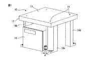
図1は、本発明の好適な実施形態に係るロボット用架台(以降、単に「架台」とも称する)10の概略構成を示す斜視図である。架台10は、図3又は図4に示したロボット機構部102等のロボット機構部(図示せず)が搭載される搭載部12と、搭載部12の下部に設けられて搭載部12を支持する複数(図示例では4つ)の脚部14a−14dと、を有し、ロボット機構部は搭載部12の下方に配置された制御装置16によって制御される。 FIG. 1 is a perspective view showing a schematic configuration of a robot stand (hereinafter also simply referred to as “stand”) 10 according to a preferred embodiment of the present invention. The
搭載部12はその上面13に、ロボット機構部を締結するための締結部(図示例ではタップ穴)18を有する。タップ穴18に螺合する締結ボルト(図示せず)等を用いてロボット機構部の基部を搭載部12に締結することにより、ロボット機構部を架台10に固定することができる。なお搭載部12に搭載されるロボット機構部としては、例えば6軸の多関節ロボットが挙げられるが、他の産業用ロボットも可能であり、特段の制約はない。 The
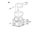
図2は、架台10を斜め下方から見た斜視図である。複数の脚部14a−14dのうちの互いに隣り合う(対角の関係にない)2つの脚部(図示例では14a及び14b)は、互いに対向して制御装置16を支持する突起部18a及び18bをそれぞれ有し、さらに、突起部18a及び18bに支持された状態の制御装置16を脚部14a及び14bに固定する固定部材(図示例ではL型レール(ブラケット))20a及び20bをそれぞれ有する。より詳細には、突起部18aは、突起部18aが形成されている脚部14aの下端から、他方の突起部18b(脚部14b)に向けて略水平方向に延び、一方、突起部18bは、突起部18bが形成されている脚部14bの下端から、他方の突起部18a(脚部14a)に向けて略水平方向に延びる。 FIG. 2 is a perspective view of the
図1又は図2に示すように、突起部18a及び18bの上に制御装置16を載置し、固定部材20a及び20bで制御装置16を脚部14a及び14bにそれぞれ固定することにより、制御装置16は突起部18a及び18bに支持された状態で架台10に固定され、これにより制御装置16と架台10(ロボット機構部)とは一体的に運搬できるようになる。従って、架台10の使用により、図3に例示した制御装置用支持部材108のような部品を使用せずとも、ロボット機構部と制御装置とを一体で運搬・移設することができる。また支持部材を不要としたことにより、架台の軽量化・低コスト化も図ることができる。 As shown in FIG. 1 or 2, the
なお図2に示すように、突起部18a及び18bの最小離隔距離Dは、脚部14aと脚部14bとの間の制御装置16の寸法(最小離隔距離Dと同方向についての制御装置16の外形寸法)Lよりも小さい(D<L)。一方、脚部14aと脚部14bとの間の(水平方向の)離隔距離は、制御装置16の外形寸法Lよりも大きい。ここで、制御装置16が突起部18a及び18bに支持されるためには、制御装置16の水平方向両端部が突起部18a及び18bに支持されていれば足りるので、両突起部間の最小離隔距離Dは、制御装置16の外形寸法L未満でかつなるべく大きいことが、架台10の重量やコストの面から好ましい。例えば、DはLの1/2以上(D≧1/2・L)、Lの2/3以上(D≧2/3・L)、Lの3/4以上(D≧3/4・L)、又はLの4/5以上(D≧4/5・L)とすることができる。或いは、各突起部の脚部からの、他の突起部に向けて突出する突出長さdを、制御装置16を支持するために必要最小限の長さ(例えば5cm以下、3cm以下又は1cm以下)としてもよい。 As shown in FIG. 2, the minimum separation distance D of the
図1又は図2では、突起部18a及び18bはいずれも矩形のタブ状部材として図示されているが、本発明はこのような形状に限られず、制御装置16(の重量)を支持できるものであればどのような形状でもよい。また固定部材20a及び20bはL型のブラケットとして図示されているが、制御装置16を脚部14a及び14bにそれぞれ固定できるものであれば、どのような構造のものも使用可能である。 In FIG. 1 or 2, the
また上述の実施形態では脚部は4本であるが、突起部や固定部材の構造については、脚部が3本や5本以上であっても4本の場合と同様の考え方が適用可能であることは明らかであろう。 In the above-described embodiment, the number of leg portions is four. However, as for the structure of the protrusion and the fixing member, the same idea as in the case of four legs can be applied even if the number of leg portions is three or five or more. It will be clear.
10、100、200 ロボット用架台
12、104 搭載部
14a−14d、106 脚部
16、110 制御装置
18a、18b 突起部
20a、20b 固定部材
102 ロボット機構部
108 制御装置用支持部材10, 100, 200
Claims (2)
Translated fromJapanese前記複数の脚部のうちの隣り合う脚部は、互いに対向して前記ロボット機構部の制御装置を支持する突起部と、前記突起部に支持された状態の前記制御装置を前記脚部に固定する固定部材とを有し、
前記搭載部の上面に、前記ロボット機構部を固定するための締結部を設け、
前記隣り合う脚部の突起部間の最小離隔距離は、前記制御装置の外形寸法の1/2以上である、
ロボット用架台。A robot pedestal comprising: a mounting portion on which a robot mechanism portion is mounted; and a plurality of legs provided at a lower portion of the mounting portion to support the mounting portion;
Adjacent leg portions of the plurality of leg portions are opposed to each other to support the control device of the robot mechanism portion, and the control device supported by the protrusion portion is fixed to the leg portion. And a fixing member that
A fastening part for fixing the robot mechanism part is provided on the upper surface of the mounting part,
The minimum separation distance between the protrusions of the adjacent leg portions is 1/2 or more of the outer dimensions of the control device.
Robot mount.
Priority Applications (4)
| Application Number | Priority Date | Filing Date | Title |
|---|---|---|---|
| JP2015204458AJP6154449B2 (en) | 2015-10-16 | 2015-10-16 | Robot stand with control device support structure |
| DE102016119173.6ADE102016119173A1 (en) | 2015-10-16 | 2016-10-10 | ROBOT FOOT BASE WITH SUPPORT STRUCTURE FOR CONTROL |
| CN201610887337.8ACN106826758B (en) | 2015-10-16 | 2016-10-11 | Robot support |
| US15/292,524US10449667B2 (en) | 2015-10-16 | 2016-10-13 | Robot pedestal having support structure for controller |
Applications Claiming Priority (1)
| Application Number | Priority Date | Filing Date | Title |
|---|---|---|---|
| JP2015204458AJP6154449B2 (en) | 2015-10-16 | 2015-10-16 | Robot stand with control device support structure |
Publications (2)
| Publication Number | Publication Date |
|---|---|
| JP2017074652A JP2017074652A (en) | 2017-04-20 |
| JP6154449B2true JP6154449B2 (en) | 2017-06-28 |
Family
ID=58456265
Family Applications (1)
| Application Number | Title | Priority Date | Filing Date |
|---|---|---|---|
| JP2015204458AActiveJP6154449B2 (en) | 2015-10-16 | 2015-10-16 | Robot stand with control device support structure |
Country Status (4)
| Country | Link |
|---|---|
| US (1) | US10449667B2 (en) |
| JP (1) | JP6154449B2 (en) |
| CN (1) | CN106826758B (en) |
| DE (1) | DE102016119173A1 (en) |
Families Citing this family (1)
| Publication number | Priority date | Publication date | Assignee | Title |
|---|---|---|---|---|
| JP6154449B2 (en)* | 2015-10-16 | 2017-06-28 | ファナック株式会社 | Robot stand with control device support structure |
Family Cites Families (52)
| Publication number | Priority date | Publication date | Assignee | Title |
|---|---|---|---|---|
| US201047A (en)* | 1878-03-05 | Improvement in meal-bins | ||
| US919052A (en)* | 1908-04-20 | 1909-04-20 | Lewis W Miller | Combination-table. |
| US1179955A (en)* | 1913-05-07 | 1916-04-18 | U S Steel Furniture Company | Furniture. |
| US1880386A (en)* | 1931-08-29 | 1932-10-04 | Gray Joseph | Baker's bench |
| US2348043A (en)* | 1942-10-27 | 1944-05-02 | Singer Mfg Co | Stand for sewing machines |
| US3533586A (en)* | 1969-03-12 | 1970-10-13 | Sidnor Tebbs Chichester Jr | Support system for furniture and the like |
| US3856371A (en)* | 1973-10-17 | 1974-12-24 | Gen Metalcraft Inc | Knock-down desk construction |
| US3852865A (en)* | 1973-10-30 | 1974-12-10 | Universal Instruments Corp | Semi automatic electronic component assembler |
| FR2369055A1 (en) | 1976-10-29 | 1978-05-26 | Creusot Loire | DIS |
| JPS5443381A (en)* | 1977-09-12 | 1979-04-05 | Hitachi Ltd | Assembly line of parts for electronic equipment |
| US4813125A (en)* | 1987-06-08 | 1989-03-21 | Utica Enterprises, Inc. | Method and apparatus for establishing the position of a datum reference from an object having dimensional variations within a tolerance range |
| US5072506A (en)* | 1990-04-30 | 1991-12-17 | Utica Enterprises, Inc. | Position seeking apparatus |
| US5539975A (en)* | 1993-09-08 | 1996-07-30 | Allen-Bradley Company, Inc. | Control system and equipment configuration for a modular product assembly platform |
| JPH08157A (en)* | 1994-06-17 | 1996-01-09 | Danraku:Kk | Noodle and machine for extruding noodle |
| JPH081574A (en) | 1994-06-23 | 1996-01-09 | Fanuc Ltd | Robot device |
| JPH08168990A (en)* | 1994-12-14 | 1996-07-02 | Fanuc Ltd | Cooling device for motor of industrial robot |
| DE29711523U1 (en) | 1997-07-02 | 1998-07-30 | Kuka Roboter GmbH, 86165 Augsburg | robot |
| DE19838631A1 (en)* | 1998-08-26 | 2000-03-02 | Benjamin Blumenschein | Base frame for domestic appliance has support plate with quadrangular outline and mounting surface |
| US7063301B2 (en)* | 2000-11-03 | 2006-06-20 | Applied Materials, Inc. | Facilities connection bucket for pre-facilitation of wafer fabrication equipment |
| US6494419B2 (en)* | 2001-05-11 | 2002-12-17 | Lucas Pai | Foldable stand |
| US6763573B2 (en)* | 2001-11-19 | 2004-07-20 | Lms-Walt, Inc. | Assembly system for monitoring proper fastening of an article of assembly at more than one location |
| US6715391B2 (en)* | 2002-03-12 | 2004-04-06 | Tian Wang Wang | Device for securing various table saws to work table |
| EP1515632B1 (en)* | 2002-06-05 | 2008-06-11 | Acketts Group Limited | Plinth for automated teller machine |
| JP3722109B2 (en)* | 2002-07-05 | 2005-11-30 | ダイキン工業株式会社 | Air conditioner outdoor unit |
| EP1452265B1 (en)* | 2003-02-26 | 2005-04-20 | FELSOMAT GmbH & Co. KG | Base platform for a manipulation device and manipulation device |
| DE10335570A1 (en) | 2003-07-31 | 2005-02-24 | Daimlerchrysler Ag | Mobile work holding robot has body carrying a camera and system of multiple linear control struts holding magnetic work platform with interconnecting member to similar units |
| US7043848B2 (en)* | 2003-11-26 | 2006-05-16 | The Micromanipulator Company | Method and apparatus for maintaining accurate positioning between a probe and a DUT |
| US7229333B2 (en)* | 2004-03-25 | 2007-06-12 | Gary Bamesberger | Method and system for the distribution and maintenance of entertainment-related objects and devices |
| KR100548306B1 (en)* | 2004-05-18 | 2006-02-02 | 엘지전자 주식회사 | Vibration Insulation Refrigerator |
| JP2007185735A (en)* | 2006-01-12 | 2007-07-26 | Fujifilm Corp | Suction head for stick parts |
| US20090084621A1 (en)* | 2007-09-27 | 2009-04-02 | Giovannini Mario R | Rack-mounted service center having separately removable housing |
| US8761938B2 (en)* | 2008-04-18 | 2014-06-24 | David Jenkinson | Robotic device tester |
| US7810782B1 (en)* | 2008-08-28 | 2010-10-12 | Driscoll Mark M | Clothes cleaning device support system |
| US8693916B2 (en)* | 2009-06-05 | 2014-04-08 | Kabushiki Kaisha Toshiba | Stabilizer, image forming apparatus, and stabilizer mounting method |
| US8424136B2 (en)* | 2010-02-01 | 2013-04-23 | Impact Athletic, Llc | Mobile treatment table |
| JP5653073B2 (en)* | 2010-05-19 | 2015-01-14 | キヤノン株式会社 | Robot cell device and production system |
| JP5755038B2 (en)* | 2010-06-28 | 2015-07-29 | キヤノン株式会社 | Assembly equipment and production system |
| JP5679711B2 (en)* | 2010-07-06 | 2015-03-04 | キヤノン株式会社 | Robot system and gripping method |
| DE102010027280A1 (en) | 2010-07-16 | 2012-01-19 | Kuka Roboter Gmbh | Robot integrated workplace |
| US8245649B1 (en)* | 2010-07-30 | 2012-08-21 | Ratliff Timothy S | Specialized table apparatus |
| DE202010008616U1 (en) | 2010-09-23 | 2011-03-31 | Battenberg, Günther | Device comprising a climatic chamber |
| US20120193505A1 (en)* | 2011-01-28 | 2012-08-02 | Baron James A | Vibration isolation system for rooftop mounted hvac equipment |
| EP2689889B1 (en)* | 2011-03-24 | 2015-07-22 | Murata Machinery, Ltd. | Machine tool system |
| US9004478B2 (en)* | 2012-05-22 | 2015-04-14 | Lincoln Global, Inc. | Welding workbench assembly with wraparound dual stage barriers |
| US9052120B2 (en)* | 2012-09-14 | 2015-06-09 | Miami Tech, Inc. | Equipment stand |
| US10071478B2 (en)* | 2013-12-23 | 2018-09-11 | Robert Kevin Houston | Parallel robot bracketing system |
| CN104743327B (en)* | 2013-12-31 | 2017-09-12 | 深圳富泰宏精密工业有限公司 | Automated exchanged cutter machine |
| US20160199985A1 (en)* | 2015-01-08 | 2016-07-14 | Design & Assembly Concepts, Inc. | System and method for automated affixing of decorative objects to a surface |
| US9526375B2 (en)* | 2015-01-16 | 2016-12-27 | Revoace Inc. | Connecting structure for barbecue grill |
| JP6154449B2 (en)* | 2015-10-16 | 2017-06-28 | ファナック株式会社 | Robot stand with control device support structure |
| JP6686644B2 (en)* | 2016-04-06 | 2020-04-22 | セイコーエプソン株式会社 | Robots and robot systems |
| JP6542830B2 (en)* | 2017-04-05 | 2019-07-10 | ファナック株式会社 | Robot stand |
- 2015
- 2015-10-16JPJP2015204458Apatent/JP6154449B2/enactiveActive
- 2016
- 2016-10-10DEDE102016119173.6Apatent/DE102016119173A1/enactivePending
- 2016-10-11CNCN201610887337.8Apatent/CN106826758B/enactiveActive
- 2016-10-13USUS15/292,524patent/US10449667B2/enactiveActive
Also Published As
| Publication number | Publication date |
|---|---|
| CN106826758B (en) | 2018-03-06 |
| US10449667B2 (en) | 2019-10-22 |
| CN106826758A (en) | 2017-06-13 |
| DE102016119173A1 (en) | 2017-04-20 |
| JP2017074652A (en) | 2017-04-20 |
| US20170106529A1 (en) | 2017-04-20 |
Similar Documents
| Publication | Publication Date | Title |
|---|---|---|
| JP2011224742A (en) | Robot cell | |
| US9149892B2 (en) | Welding power supply roll cage with incorporated lift handles | |
| JP2014222957A (en) | Base for preventing housing overturn | |
| JP5682721B1 (en) | Industrial robot and its mounting unit | |
| JP6154449B2 (en) | Robot stand with control device support structure | |
| JP4313269B2 (en) | Assembly equipment | |
| JP5731611B2 (en) | Injection molding machine with transformer | |
| JP2016165363A (en) | Desk apparatus | |
| WO2017203771A1 (en) | Casing separation mechanism | |
| JPWO2019082379A1 (en) | Railcar equipment enclosure | |
| KR200484260Y1 (en) | Floor structure for ship | |
| US20180056508A1 (en) | Motor unit and robot | |
| JP2009171793A (en) | Method of extension of cable rack | |
| JP2010208859A (en) | Tower crane frame, tower crane supporting method, and tower crane frame mounting structure | |
| JP5186182B2 (en) | Adjustment mechanism and table | |
| JP2016139638A (en) | Transformer | |
| JP7132744B2 (en) | Optional unit and furniture with top plate | |
| JP7246171B2 (en) | Box body for storing electrical equipment | |
| JP2018154966A (en) | Automatic warehouse with ladder and stacker crane with ladder attached | |
| JP6699540B2 (en) | Floor board mounting member | |
| JP6812288B2 (en) | Battery stand | |
| JP2011021443A (en) | Ceiling joist with shape retention member, ceiling joist unit, and structure for ceiling surface | |
| KR20240116976A (en) | Control device | |
| JP6704634B2 (en) | Base expansion structure for electrical and electronic equipment storage boxes | |
| JP6158988B1 (en) | Case separation mechanism |
Legal Events
| Date | Code | Title | Description |
|---|---|---|---|
| A521 | Written amendment | Free format text:JAPANESE INTERMEDIATE CODE: A523 Effective date:20170131 | |
| TRDD | Decision of grant or rejection written | ||
| A01 | Written decision to grant a patent or to grant a registration (utility model) | Free format text:JAPANESE INTERMEDIATE CODE: A01 Effective date:20170509 | |
| A61 | First payment of annual fees (during grant procedure) | Free format text:JAPANESE INTERMEDIATE CODE: A61 Effective date:20170601 | |
| R150 | Certificate of patent or registration of utility model | Ref document number:6154449 Country of ref document:JP Free format text:JAPANESE INTERMEDIATE CODE: R150 |