JP6153414B2 - Insertion system and method for adjusting shape detection characteristics of shape sensor - Google Patents
Insertion system and method for adjusting shape detection characteristics of shape sensorDownload PDFInfo
- Publication number
- JP6153414B2 JP6153414B2JP2013163348AJP2013163348AJP6153414B2JP 6153414 B2JP6153414 B2JP 6153414B2JP 2013163348 AJP2013163348 AJP 2013163348AJP 2013163348 AJP2013163348 AJP 2013163348AJP 6153414 B2JP6153414 B2JP 6153414B2
- Authority
- JP
- Japan
- Prior art keywords
- unit
- insertion device
- shape
- held
- holding
- Prior art date
- Legal status (The legal status is an assumption and is not a legal conclusion. Google has not performed a legal analysis and makes no representation as to the accuracy of the status listed.)
- Active
Links
Images


Classifications
- A—HUMAN NECESSITIES
- A61—MEDICAL OR VETERINARY SCIENCE; HYGIENE
- A61B—DIAGNOSIS; SURGERY; IDENTIFICATION
- A61B1/00—Instruments for performing medical examinations of the interior of cavities or tubes of the body by visual or photographical inspection, e.g. endoscopes; Illuminating arrangements therefor
- A61B1/005—Flexible endoscopes
- A61B1/009—Flexible endoscopes with bending or curvature detection of the insertion part
- A—HUMAN NECESSITIES
- A61—MEDICAL OR VETERINARY SCIENCE; HYGIENE
- A61B—DIAGNOSIS; SURGERY; IDENTIFICATION
- A61B1/00—Instruments for performing medical examinations of the interior of cavities or tubes of the body by visual or photographical inspection, e.g. endoscopes; Illuminating arrangements therefor
- A61B1/00002—Operational features of endoscopes
- A61B1/00057—Operational features of endoscopes provided with means for testing or calibration
- A—HUMAN NECESSITIES
- A61—MEDICAL OR VETERINARY SCIENCE; HYGIENE
- A61B—DIAGNOSIS; SURGERY; IDENTIFICATION
- A61B1/00—Instruments for performing medical examinations of the interior of cavities or tubes of the body by visual or photographical inspection, e.g. endoscopes; Illuminating arrangements therefor
- A61B1/00147—Holding or positioning arrangements
- A61B1/00154—Holding or positioning arrangements using guiding arrangements for insertion
- A—HUMAN NECESSITIES
- A61—MEDICAL OR VETERINARY SCIENCE; HYGIENE
- A61B—DIAGNOSIS; SURGERY; IDENTIFICATION
- A61B1/00—Instruments for performing medical examinations of the interior of cavities or tubes of the body by visual or photographical inspection, e.g. endoscopes; Illuminating arrangements therefor
- A61B1/005—Flexible endoscopes
- A61B1/0051—Flexible endoscopes with controlled bending of insertion part
- A61B1/0057—Constructional details of force transmission elements, e.g. control wires
- A—HUMAN NECESSITIES
- A61—MEDICAL OR VETERINARY SCIENCE; HYGIENE
- A61B—DIAGNOSIS; SURGERY; IDENTIFICATION
- A61B1/00—Instruments for performing medical examinations of the interior of cavities or tubes of the body by visual or photographical inspection, e.g. endoscopes; Illuminating arrangements therefor
- A61B1/005—Flexible endoscopes
- A61B1/01—Guiding arrangements therefore
- A—HUMAN NECESSITIES
- A61—MEDICAL OR VETERINARY SCIENCE; HYGIENE
- A61B—DIAGNOSIS; SURGERY; IDENTIFICATION
- A61B1/00—Instruments for performing medical examinations of the interior of cavities or tubes of the body by visual or photographical inspection, e.g. endoscopes; Illuminating arrangements therefor
- A61B1/04—Instruments for performing medical examinations of the interior of cavities or tubes of the body by visual or photographical inspection, e.g. endoscopes; Illuminating arrangements therefor combined with photographic or television appliances
- A61B1/045—Control thereof
- A—HUMAN NECESSITIES
- A61—MEDICAL OR VETERINARY SCIENCE; HYGIENE
- A61B—DIAGNOSIS; SURGERY; IDENTIFICATION
- A61B34/00—Computer-aided surgery; Manipulators or robots specially adapted for use in surgery
- A61B34/20—Surgical navigation systems; Devices for tracking or guiding surgical instruments, e.g. for frameless stereotaxis
- A61B2034/2046—Tracking techniques
- A61B2034/2061—Tracking techniques using shape-sensors, e.g. fiber shape sensors with Bragg gratings
- A—HUMAN NECESSITIES
- A61—MEDICAL OR VETERINARY SCIENCE; HYGIENE
- A61B—DIAGNOSIS; SURGERY; IDENTIFICATION
- A61B2562/00—Details of sensors; Constructional details of sensor housings or probes; Accessories for sensors
- A61B2562/02—Details of sensors specially adapted for in-vivo measurements
- A61B2562/0261—Strain gauges
- A61B2562/0266—Optical strain gauges
- A—HUMAN NECESSITIES
- A61—MEDICAL OR VETERINARY SCIENCE; HYGIENE
- A61B—DIAGNOSIS; SURGERY; IDENTIFICATION
- A61B50/00—Containers, covers, furniture or holders specially adapted for surgical or diagnostic appliances or instruments, e.g. sterile covers
- A61B50/20—Holders specially adapted for surgical or diagnostic appliances or instruments
- A61B50/22—Racks
Landscapes
- Health & Medical Sciences (AREA)
- Life Sciences & Earth Sciences (AREA)
- Surgery (AREA)
- Biomedical Technology (AREA)
- Medical Informatics (AREA)
- Optics & Photonics (AREA)
- Pathology (AREA)
- Radiology & Medical Imaging (AREA)
- Biophysics (AREA)
- Engineering & Computer Science (AREA)
- Physics & Mathematics (AREA)
- Heart & Thoracic Surgery (AREA)
- Nuclear Medicine, Radiotherapy & Molecular Imaging (AREA)
- Molecular Biology (AREA)
- Animal Behavior & Ethology (AREA)
- General Health & Medical Sciences (AREA)
- Public Health (AREA)
- Veterinary Medicine (AREA)
- Endoscopes (AREA)
- Instruments For Viewing The Inside Of Hollow Bodies (AREA)
Description
Translated fromJapanese本発明は、挿入システム及び形状センサの形状検出特性を調整する方法に関する。 The present invention relates to an insertion system and a method for adjusting the shape detection characteristics of a shape sensor.
一般に、入口が狭い空間内を撮影するためのシステムとして、先端にカメラが設けられた細長形状を有する挿入システムが知られている。このような挿入システムには、各種内視鏡が含まれる。先端にカメラが設けられた細長形状の部分が可撓性である挿入システムが知られている。このような挿入システムにおいて、可撓部分の形状を取得するための機構が設けられることがある。例えば特許文献1には、内視鏡において可撓部分の形状を取得するためのファイバセンサに係る技術が開示されている。 In general, an insertion system having an elongated shape in which a camera is provided at the tip is known as a system for photographing a space where the entrance is narrow. Such insertion systems include various endoscopes. There is known an insertion system in which an elongated portion provided with a camera at the tip is flexible. In such an insertion system, a mechanism for acquiring the shape of the flexible portion may be provided. For example, Patent Document 1 discloses a technique related to a fiber sensor for acquiring the shape of a flexible portion in an endoscope.
特許文献1には、次のような内視鏡が開示されている。内視鏡には、複数のフレキシブルな曲がり検出用光ファイバが設けられている。曲がり検出用光ファイバは、曲がり検出部を有しており、曲がり検出部の角度に対応して光の伝達量が変化する。この曲がり検出用光ファイバは、可撓性の帯状部材に検出部が並ぶように取り付けられて、内視鏡内にほぼ全長にわたって挿通配置されている。各曲がり検出用光ファイバの光伝達量に基づいて、各曲がり検出部が位置する部分における帯状部材の屈曲状態が検出される。この屈曲状態は、内視鏡の屈曲状態としてモニタ画面に表示される。 Patent Document 1 discloses the following endoscope. The endoscope is provided with a plurality of flexible bending detection optical fibers. The bending detection optical fiber has a bending detection unit, and the amount of transmitted light changes according to the angle of the bending detection unit. This bending detection optical fiber is attached to a flexible belt-like member so that the detection portions are arranged, and is inserted and disposed almost throughout the endoscope. Based on the light transmission amount of each bending detection optical fiber, the bending state of the band-shaped member in the portion where each bending detection unit is located is detected. This bent state is displayed on the monitor screen as the bent state of the endoscope.
特許文献1に開示されているような光ファイバセンサを含めて、センサは、時間経過とともに出力特性が変化することがある。高い検出精度を維持するためには、使用前にセンサの校正を行う必要がある。 The output characteristics of the sensors, including the optical fiber sensor disclosed in Patent Document 1, may change with time. In order to maintain high detection accuracy, it is necessary to calibrate the sensor before use.
そこで本発明は、容易に校正が行われる挿入システム及び形状センサの形状検出特性を容易に調整する方法を提供することを目的とする。 Therefore, an object of the present invention is to provide an insertion system in which calibration is easily performed and a method for easily adjusting the shape detection characteristics of the shape sensor.
前記目的を果たすため、本発明の一態様によれば、挿入システムは、細長形状の可撓性を有する挿入部を備える挿入装置と、前記挿入部の形状を検出するための形状センサと、前記挿入部の一端が垂下するように前記挿入部の他端側において前記挿入装置を保持する挿入装置保持部と、前記挿入装置が前記挿入装置保持部に保持されているときに、前記形状センサの形状検出特性を調整するための調整値を決定する調整部とを具備する。 To achieve the above object, according to an aspect of the present invention, an insertion system includes an insertion device including an elongated flexible insertion portion, a shape sensor for detecting the shape of the insertion portion, An insertion device holding portion for holding the insertion device on the other end side of the insertion portion such that one end of the insertion portion hangs down, and when the insertion device is held by the insertion device holding portion, And an adjustment unit that determines an adjustment value for adjusting the shape detection characteristic.
また、本発明の一態様によれば、形状センサの形状検出特性を調整する方法は、細長形状の可撓性を有する挿入部を備える挿入装置と、前記挿入部の形状を検出するための形状センサとを備える挿入システムの前記形状センサの形状検出特性を調整する方法であって、前記挿入部の一端が垂下するように前記挿入部の他端側において前記挿入装置が保持されているか否かを検出することと、前記挿入装置が保持されているときに、前記形状センサの形状検出特性を調整するための調整値を決定することとを具備する。 According to another aspect of the present invention, a method for adjusting the shape detection characteristic of a shape sensor includes an insertion device including an elongated flexible insertion portion, and a shape for detecting the shape of the insertion portion. A method for adjusting a shape detection characteristic of the shape sensor of an insertion system including a sensor, wherein the insertion device is held on the other end side of the insertion portion such that one end of the insertion portion hangs down And determining an adjustment value for adjusting a shape detection characteristic of the shape sensor when the insertion device is held.
本発明によれば、容易に校正が行われる挿入システム及び形状センサの形状検出特性を容易に調整する方法を提供できる。 According to the present invention, it is possible to provide an insertion system in which calibration is easily performed and a method for easily adjusting the shape detection characteristics of the shape sensor.
[第1の実施形態]
第1の実施形態について図面を参照して説明する。本実施形態は、挿入システムの一例として医療用内視鏡に係る。本実施形態に係る挿入システム1の構成例の概略を図1及び図2に示す。図1は、挿入システム1の外観の概略を表すイメージ図であり、図2は、挿入システム1の構成例の概略を表すブロック図である。[First Embodiment]
A first embodiment will be described with reference to the drawings. The present embodiment relates to a medical endoscope as an example of an insertion system. The outline of the structural example of the insertion system 1 which concerns on this embodiment is shown in FIG.1 and FIG.2. FIG. 1 is an image diagram showing an outline of the appearance of the insertion system 1, and FIG. 2 is a block diagram showing an outline of a configuration example of the insertion system 1.
図1及び図2に示すように、挿入システム1は、挿入装置100と、本体部200と、表示部300とを備える。挿入装置100は、例えば内視鏡である。本体部200は、挿入装置100と接続されており、挿入装置100の制御や各種演算等を行う。表示部300は、本体部200に接続された一般的なディスプレイであり、挿入装置100によって得られた画像や、挿入装置100の形状や、各種制御パラメータ等を表示する。 As shown in FIGS. 1 and 2, the insertion system 1 includes an
挿入装置100は、被挿入体に挿入されて、被挿入体の内部を撮像する。撮像により得られた画像は、表示部300に表示される。また、挿入システム1は、挿入装置100の現在の形状を検出する機構を有している。検出された挿入装置100の現在の形状は、表示部300に表示される。 The
図1に示すように、本体部200及び表示部300は、ラック400に設置されている。挿入装置100は、使用されていない状態においては、ラック400に設けられたハンガーである挿入装置保持部420に掛けられる。挿入装置保持部420には、挿入装置100が配置されているか否かを検出する保持状態検出部500が設けられている。 As shown in FIG. 1, the
挿入装置100は、最長形状をした可撓性の挿入部110と、挿入部110の基端側に設けられた操作部120とを含む。挿入部110は、被挿入体に挿入される。挿入部110の先端付近には、能動的に湾曲する湾曲部115が設けられている。操作部120は、使用者が把持する部分であり、使用者が挿入部110に係る操作を行うための各種操作部を有する。例えば操作部120には、湾曲部115の湾曲状態を変化させるための操作ノブ125が設けられている。操作部120と本体部200とは、ケーブル190によって接続されている。 The
挿入部110には、挿入部110の形状を検出するための形状検出部130が設けられている。また、挿入装置100の先端部には、撮像素子140が設けられている。撮像素子140によって、被挿入体の内部の画像が取得され得る。撮像素子140を用いて得られた画像信号は、ケーブル190を介して本体部200に送信される。また、挿入部110の先端には、照明用の光を射出する図示しない光射出部が設けられている。この光射出部からは、本体部200からケーブル190及び挿入部110内を光ファイバを介して導かれた照明光が射出される。 The
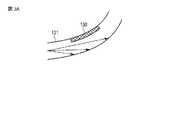
形状検出部130について簡単に説明する。形状検出部130を含む形状センサには、例えばファイバセンサが用いられ得る。ファイバセンサの一例について図3A、図3B及び図3C並びに図4を参照して説明する。ファイバセンサは、光ファイバ131を備える。図2に示すように、本体部200には、この光ファイバ131によって導光される光を射出する発光部212と、光ファイバによって導光された光を受光する受光部214とが設けられている。 The
ファイバセンサの動作原理を説明する。光ファイバ131には、形状検出部130が設けられている。形状検出部130においては、光ファイバ131のクラッドが除去されてコアが露出しており、この部分には光吸収部材が塗布されている。その結果、光ファイバ131の湾曲の状態に応じて光ファイバ131によって導かれる光の光量が変化する。なお、図1に示されている形状検出部130は、光ファイバ131に設けられた形状検出部130の位置を模式的に表している。 The operation principle of the fiber sensor will be described. The
例えば図3Aに示すように、形状検出部130が内側となるように光ファイバ131が湾曲しているとき、光ファイバ131による光伝達率は高くなる。一方、図3Cに示すように、形状検出部130が外側となるように光ファイバ131が湾曲しているとき、光ファイバ131による光伝達率は低くなる。図3Bに示すように、光ファイバ131が湾曲していないとき、光ファイバ131による光伝達率は、図3Aに示す場合よりも低く図3Cに示す場合よりも高くなる。このような光ファイバ131が挿入部110に挿通されている。本体部200に設けられた発光部212から射出された光は、光ファイバ131に入射し、形状検出部130を通過して、その後再び本体部200に導かれ、受光部214で検出される。受光部214は、光ファイバ131によって導かれた光の光量を測定する。この測定した受光量に基づいて、形状検出部130が設けられた領域の挿入部110の湾曲量が算出される。 For example, as shown in FIG. 3A, when the
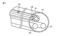
挿入部110には、図4に示すように、複数の光ファイバ131が束ねられて配置されている。挿入部110の各部における直交する2方向(例えばX軸方向とY軸方向)の湾曲量を検出するために、ある一の方向(例えばX軸方向)に形状検出部130が設けられている光ファイバ131と、この一の方向と直交する方向(例えばY軸方向)に形状検出部130が設けられている光ファイバ131とが一対をなして挿入部110に設けられている。さらに、挿入部110の長手軸方向に異なる位置に形状検出部130が設けられた複数の光ファイバ131が、挿入部110に設けられている。なお、図4には、光ファイバ131の他、挿入部110の先端から射出される照明光を伝達する照明光用光ファイバ142と、撮像素子140用の配線141とが描かれている。 As shown in FIG. 4, a plurality of
ここでは、1本の光ファイバ131に1箇所の形状検出部130が設けられている例を示したが、1本の光ファイバに複数の形状検出部130が設けられていてもよい。例えば、異なる波長特性を持った光吸収部材が各形状検出部130に塗布されることで、各形状検出部130の湾曲量に基づいて異なる波長の光量が変化するように構成されてもよい。 Here, an example in which one
このように、形状検出部130、光ファイバ131、発光部212及び受光部214等は、全体として形状センサ135を形成する。 As described above, the
図2に戻って挿入システム1の構成について説明を続ける。図2に示すように本体部200には、形状演算部220と、調整部230と、メモリ240と、画像処理部250とが設けられている。形状演算部220は、受光部214から形状検出部130に係る受光量に係る値を取得する。形状演算部220は、この受光量に基づいて、挿入部110の形状を算出する。形状演算部220は、算出した挿入部110の形状を表示部300に表示させる。 Returning to FIG. 2, the description of the configuration of the insertion system 1 will be continued. As shown in FIG. 2, the
形状センサ135の光ファイバの光伝達量の変化Δlと、湾曲検出部の湾曲量φの関係式は、例えば次式(1)のように求められている。 A relational expression between the change Δl in the optical transmission amount of the optical fiber of the
φ=f(Δl) (1)
形状演算部は、式(1)と光伝達量の変化Δlとに基づいて、各湾曲検出部の湾曲量φを算出する。さらに、形状演算部220は、各湾曲検出部の湾曲量φと、既知である各湾曲検出部の間隔の情報から、挿入部の形状を演算する。なお、形状演算部220は、式(1)を用いて直接計算をしなくてもよい。すなわち、式(1)に相当する変換テーブルが用意されており、形状演算部220がこの変換テーブルに基づいて、湾曲量を算出してもよい。φ = f (Δl) (1)
The shape calculation unit calculates the bending amount φ of each bending detection unit based on the equation (1) and the change Δl in the light transmission amount. Furthermore, the
調整部230は、発光部212、受光部214、形状演算部220及び保持状態検出部500と接続されている。調整部230は、形状センサ135に係る状態を検出し、調整値を決定して、この調整値に基づいて形状センサ135に係る特性を調整する。形状演算部220及び調整部230は、メモリ240と接続されている。形状演算部220及び調整部230は、必要に応じてメモリ240に記憶された情報を用いて各種演算を行う。例えば上記式(1)やそれに相当する変換テーブルは、メモリ240に記憶される。 The adjusting
画像処理部250は、挿入装置100の撮像素子140に接続されている。画像処理部250は、撮像素子140によって得られて画像データに基づいて、表示画像を作成し、その表示画像を表示部300に表示させる。 The
挿入装置保持部420及び保持状態検出部500についてさらに説明する。挿入装置保持部420は、挿入装置100の操作部120、又は操作部120の近傍を保持する。ここで、操作部120の近傍とは、例えば操作部120及び接続ケーブルの操作部120の近傍の範囲を意味する。なお、挿入装置保持部420は、挿入部110を保持してもよい。しかしながら、被挿入体として例えば人体が想定されているとき、挿入部110は、清潔に保たれる必要がある。このため、挿入装置保持部420は、挿入部110以外を保持することが好ましい。 The insertion
保持状態検出部500について図5を参照して説明する。保持状態検出部500は、例えば、挿入装置保持部420に設けられた機械的なスイッチを含む。保持状態検出部500は、挿入装置保持部420が挿入装置100の操作部120を保持するときに、挿入装置保持部420と操作部120との間に位置するように配置されている。操作部120が挿入装置保持部420に保持されるとき、挿入装置100の重さによって保持状態検出部500のスイッチが押されON状態になる。保持状態検出部500は、挿入装置100が挿入装置保持部420に保持されているか否かに係る情報を調整部230に出力する。 The holding
本実施形態に係る挿入システム1の動作について説明する。挿入システム1は、形状検出部130を用いた挿入部110の形状検出に係る調整を行う機能を有する。光ファイバ131を用いた形状検出部130の出力は経年変化する。すなわち、長期的にみると、形状検出部130に係る光学系の接点の状態が変化したり、挿入部110への形状検出部130の組込み状態が変わったりすることで、受光部214によって受光される光量特性が変化することがある。 Operation | movement of the insertion system 1 which concerns on this embodiment is demonstrated. The insertion system 1 has a function of performing adjustment related to the shape detection of the
例えば、挿入部110の曲率(湾曲量)と受光量との関係の模式図を図6に示す。例えば曲率と受光量との関係が、当初は実線912に示すような関係であったとする。このような特性を有する形状検出部130において、形状検出部130の光学系の光学的な接点にゴミが入る等して導光効率が下がると、曲率と受光量との関係は、破線914に示すように変化する。例えば上記式(1)が実線912に示すような当初の関係に基づくとき、この関係が変化すると正確な湾曲量の算出が行われなくなる。 For example, FIG. 6 shows a schematic diagram of the relationship between the curvature (amount of bending) of the
そこで本実施形態に係る挿入システム1は、形状検出部130に係る出力値の経年変化を補正して、正確な湾曲量の算出を行うための機構を有する。 Therefore, the insertion system 1 according to the present embodiment has a mechanism for correcting an aging change of the output value related to the
挿入システム1の調整部230に係る調整値決定処理を図7に示すフローチャートを参照して説明する。ステップS101において、調整部230は、保持状態検出部500から保持状態に係る情報を取得する。ステップS102において、調整部230は、挿入装置100が挿入装置保持部420に保持されたか否かを判定する。保持されていないと判定されたとき、処理はステップS101に戻る。一方、保持されたと判定されたとき、処理はステップS103に進む。 The adjustment value determination process related to the
挿入装置100が挿入装置保持部420に保持されているとき、挿入部110は真っ直ぐに垂下した状態となる。調整部230は、以下の処理で、このときの形状検出部130に係る出力が初期状態、すなわち、例えば上記式(1)の関係に適合した出力になるように、調整を行う。 When the
すなわち、ステップS103において、調整部230は、受光部214から出力された現在の受光量と、初期状態における挿入部110が真直状態における受光量とを比較する。ステップS104において、調整部230は、現在の受光量と、初期状態において挿入部110が真直状態である場合の受光量との関係を調整するための調整値を決定し出力する。調整値が決定されたとき、その旨が表示部300に表示されてもよい。ステップS104の後、調整値決定処理は終了する。 That is, in step S103, the
現在の受光量と、初期状態において挿入部110が真直状態である場合の受光量との関係の調整方法には、いくつかの態様が考えられる。この調整は、例えば発光部212の射出光量の変更によって行われ得る。すなわち、現在の受光量と、初期状態における挿入部110が真直状態における受光量とが等しくなるように、発光部212の射出光量が調整される。例えば現在の受光量が初期状態における受光量よりも低いとき、現在の受光量が初期状態の受光量と等しくなるように、射出光量が高められる。この場合、調整値は発光部212に出力され、発光部212はこの調整値を用いて発光量を調整する。 There are several possible modes for adjusting the relationship between the current amount of received light and the amount of received light when the
また、この調整は、例えば受光部214の露光時間や、ゲインの変更によって行われ得る。すなわち、現在の受光量による出力値と、初期状態における挿入部110が真直状態における受光量による出力値とが等しくなるように受光部214の露光時間や、ゲインが調整される。この場合、調整値は受光部214に出力され、受光部214はこの調整値を用いて受光量を調整する。 Further, this adjustment can be performed, for example, by changing the exposure time of the
また、この調整は、形状演算部220で用いられる式(1)や変換テーブルを変更することによって行われ得る。この場合、調整値は形状演算部220に出力され、形状演算部220はこの調整値をもち形状演算を行う。なお、これらの調整のいくつかが組み合わされて用いられてもよい。 Further, this adjustment can be performed by changing the expression (1) used in the
以降、挿入装置100が使用されるとき、形状演算部220は、調整部230によって調整がなされた形状センサ135に係る値に基づいて、挿入部110の形状を算出する。形状演算部220は、算出した挿入部110の形状を表示部300に表示させる。使用者は、表示部300に表示された挿入部110の形状を確認しながら、挿入装置100を操作して、被挿入体内部の観察等を行う。 Thereafter, when the
本実施形態によれば、調整部230によって形状演算部220による挿入部110の形状算出に係る情報が調整されるので、形状演算部220は、経年変化に関わらず挿入部110の形状を正確に算出することができる。この調整部230による調整値決定処理は、挿入装置100が使用されずに挿入装置保持部420に配置されているときに行われる。したがって、この調整にあたって使用者は特別な作業を行う必要がない。このように、本実施形態によれば使用者に負担なく簡便に調整が行われる。さらに、挿入装置100が挿入装置保持部420に配置されているか否かの判定が、保持状態検出部500から出力される信号に基づいて行われる。すなわち、この調整は自動的に開始され、使用者は煩わされない。本実施形態の保持状態検出部500には、機械的スイッチが用いられている。機械的スイッチによれば、簡単な構成で挿入装置100が挿入装置保持部420に配置されているか否かが検出され得る。 According to the present embodiment, the
本実施形態として、医療用内視鏡に係る挿入システムを一例として説明を行った。しかしながら、本実施形態に係る技術は、医療用内視鏡に限らず、工業用内視鏡、細長形状のマニピュレータ等、種々の挿入システムに適用され得る。 As this embodiment, the insertion system according to the medical endoscope has been described as an example. However, the technology according to the present embodiment is not limited to a medical endoscope, but can be applied to various insertion systems such as an industrial endoscope and an elongated manipulator.
なお、挿入装置保持部420が操作部120を保持している例を示したが、操作部120が垂下するように挿入装置保持部420が挿入部110の先端を保持してもよい。ただし、挿入装置の強度や保持のしやすさや挿入部110の先端の保護のため、本実施形態のように挿入装置保持部420が操作部120を保持することが好ましい。 Although the example in which the insertion
また、本実施形態では、形状センサ135として光ファイバを用いたワイヤセンサを例に説明した。しかしながら、形状センサ135は、ワイヤセンサに限らない。本実施形態に係る技術は、時間経過とともに出力値が変化する種々のセンサに用いられ得る。 In the present embodiment, a wire sensor using an optical fiber has been described as an example of the
[第1の実施形態の第1の変形例]
第1の実施形態の第1の変形例について説明する。ここでは、第1の実施形態との相違点について説明し、同一の部分については、同一の符号を付してその説明を省略する。本変形例は、第1の実施形態と、保持状態検出部の構成が異なる。本変形例に係る保持状態検出部510に係る構成例の概略を図8に示す。[First Modification of First Embodiment]
A first modification of the first embodiment will be described. Here, differences from the first embodiment will be described, and the same portions will be denoted by the same reference numerals and description thereof will be omitted. This modification differs from the first embodiment in the configuration of the holding state detection unit. FIG. 8 shows an outline of a configuration example related to the holding
第1の実施形態に係る保持状態検出部500は、機械的スイッチを含む。これに対して本変形例に係る保持状態検出部510は、図8に示すように、光学的スイッチを含む。すなわち、保持状態検出部510は、発光部512及び受光部514を有する。発光部512は、光を射出する。 The holding
挿入装置保持部420に挿入装置100の操作部120が配置されているとき、発光部512から射出された光は、挿入装置100の操作部120に照射される。この光は、操作部120で反射する。操作部120で反射した光は、受光部514に入射する。受光部514は、操作部120から到来した反射光を受光し、受光した旨の信号を出力する。一方、挿入装置保持部420に操作部120が配置されていないとき、発光部512から射出された光は、受光部514で受光されない。 When the
このように、本変形例に係る保持状態検出部510は、発光部512から射出された光の反射光が、受光部514で受光されるか否かによって、挿入装置保持部420に挿入装置100の操作部120が配置されているか否かを検出する。調整部230は、受光部514から出力される信号を取得する。調整部230は、取得したこの信号に基づいて、挿入装置保持部420に操作部120が配置されているか否かを判定し、調整動作の開始を制御する。他の部分については、第1の実施形態と同様である。 As described above, the holding
本変形例によれば、第1の実施形態の機械的スイッチの場合と異なり、非接触に当該検出が行われ得る。このため、挿入装置保持部420における保持状態検出部500の設置可能な領域が広がり、設計の自由度が上がる。 According to this modification, unlike the case of the mechanical switch of the first embodiment, the detection can be performed in a non-contact manner. For this reason, a region where the holding
[第1の実施形態の第2の変形例]
第1の実施形態の第2の変形例について説明する。ここでは、第1の実施形態との相違点について説明し、同一の部分については、同一の符号を付してその説明を省略する。本変形例に係る保持状態検出部520に係る構成例の概略を図9に示す。本変形例に係る保持状態検出部520は、電気的なスイッチを有している。すなわち、挿入装置保持部420には、第1の電極522が設けられ、操作部120には、第2の電極524が設けられている。第1の電極522と第2の電極524とは、挿入装置保持部420に操作部120が配置されたときに互いに接触する位置に配設されている。本変形例に係る保持状態検出部520は、第1の電極522と第2の電極524とが接触して導通するとき、挿入装置保持部420に操作部120が配置された旨を信号を出力する。他の部分については、第1の実施形態と同様である。[Second Modification of First Embodiment]
A second modification of the first embodiment will be described. Here, differences from the first embodiment will be described, and the same portions will be denoted by the same reference numerals and description thereof will be omitted. FIG. 9 shows an outline of a configuration example related to the holding
本変形例では、保持状態検出部520は、電気的接続によって、挿入装置保持部420に操作部120が配置されたか否かを検出する。本変形例によれば、挿入装置保持部420に例えば誤って挿入装置100以外のものが配置されても、保持状態検出部520は、第2の電極524が設けられている操作部120以外のものを検出することはない。すなわち、本変形例に係る保持状態検出部520では、挿入装置保持部420に挿入装置100以外のものが配置されることによる誤検出のおそれがない。また、本変形例に係る保持状態検出部520によれば、挿入装置保持部420に正しく操作部120が配置されたか否かも判定され得る。 In the present modification, the holding
[第1の実施形態の第3の変形例]
第1の実施形態の第3の変形例について説明する。ここでは、第1の実施形態との相違点について説明し、同一の部分については、同一の符号を付してその説明を省略する。本変形例に係る挿入システム1には、図10に示すように、保持状態検出部500の代わりに、例えばスイッチやキーボードを含む入力装置530が設けられている。[Third Modification of First Embodiment]
A third modification of the first embodiment will be described. Here, differences from the first embodiment will be described, and the same portions will be denoted by the same reference numerals and description thereof will be omitted. As shown in FIG. 10, the insertion system 1 according to this modification is provided with an input device 530 including a switch and a keyboard, for example, instead of the holding
使用者は、挿入装置100が挿入装置保持部420に保持されたことを認識し、入力装置530を操作する。本変形例では、入力装置530を用いた操作によって、調整動作が開始される。 The user recognizes that the
本変形例によれば、使用者は任意のタイミングで調整動作を開始させることができる。 According to this modification, the user can start the adjustment operation at an arbitrary timing.
[第1の実施形態の第4の変形例]
第1の実施形態の第4の変形例について説明する。ここでは、第1の実施形態との相違点について説明し、同一の部分については、同一の符号を付してその説明を省略する。本変形例では、調整値決定処理が第1の実施形態と異なる。[Fourth Modification of First Embodiment]
A fourth modification of the first embodiment will be described. Here, differences from the first embodiment will be described, and the same portions will be denoted by the same reference numerals and description thereof will be omitted. In this modification, the adjustment value determination process is different from that of the first embodiment.
挿入装置100が挿入装置保持部420に保持されている状態では、挿入部110は直接保持されずに垂下しているだけである。したがって、挿入装置100が保持された直後は、挿入装置100を挿入装置保持部420に保持する際の動きによって挿入部110が静止せずに揺れている可能性がある。そこで本変形例では、挿入部110が静止するまでの待機時間が設けられている。 In a state where the
本変形に係る調整値決定処理について、図11を参照して説明する。ステップS201において、調整部230は、保持状態検出部500から保持状態に係る情報を取得する。ステップS202において、調整部230は、挿入装置100が挿入装置保持部420に保持されたか否かを判定する。保持されていないと判定されたとき、処理はステップS201に戻る。一方、保持されたと判定されたとき、処理はステップS203に進む。 The adjustment value determination process according to this modification will be described with reference to FIG. In step S <b> 201, the
ステップS203において、調整部230は、調整開始まで処理を遅延させる。すなわち、挿入装置100が挿入装置保持部420に保持されたことが検出された後、挿入部110が静止すると予測される時間だけ処理が待機する。この待機時間は、例えば5秒間といったように、適宜設定される。このようにして、挿入装置100が挿入装置保持部420に保持されて静止した後に調整のための動作が実行される。 In step S203, the
ステップS204において、調整部230は、受光部214から出力された現在の受光量と、初期状態における挿入部110が真直状態における受光量とを比較する。ステップS205において、調整部230は、現在の受光量と、初期状態において挿入部110が真直状態である場合の受光量との関係を調整するための調整値を決定し出力する。ステップS205の後、調整値決定処理は終了する。 In step S204, the
本変形例によれば、挿入装置保持部420に挿入部110が配置された直後の挿入部110が動いている状態、すなわち挿入部110が真直でない状態において調整値の決定がなされることが防止される。その結果、調整値の誤差によって挿入部110の形状が正しく算出されないことが防止される。 According to this modification, the adjustment value is prevented from being determined when the
[第2の実施形態]
第2の実施形態について説明する。ここでは、第1の実施形態との相違点について説明し、同一の部分については、同一の符号を付してその説明を省略する。本実施形態に係る挿入システム1には、湾曲部115の湾曲状態を検出する機構が設けられている。[Second Embodiment]
A second embodiment will be described. Here, differences from the first embodiment will be described, and the same portions will be denoted by the same reference numerals and description thereof will be omitted. The insertion system 1 according to the present embodiment is provided with a mechanism for detecting the bending state of the bending
本実施形態に係る挿入システム1の構成例の概略を図12に示す。この図に示すように、挿入装置100は、湾曲部115を湾曲させるための第1の操作ワイヤ157と第2の操作ワイヤ158とを備える。第1の操作ワイヤ157と第2の操作ワイヤ158との一端は、例えばチェーンである連結部材156で接続されている。連結部材156は、操作部120の操作ノブ125と連動するプーリーに係回されている。第1の操作ワイヤ157と第2の操作ワイヤ158との他端は、湾曲部115に接続されている。操作ノブ125が回転するとき、連結部材156は変位する。この変位に伴って、第1の操作ワイヤ157及び第2の操作ワイヤ158は変位する。その結果、湾曲部115は湾曲する。 The outline of the structural example of the insertion system 1 which concerns on this embodiment is shown in FIG. As shown in this figure, the
操作部120は、第1の操作ワイヤ157の変位を検出するための第1の変位検出部152と、第2の操作ワイヤ158の変位を検出するための第2の変位検出部154とを備える。第1の変位検出部152と第2の変位検出部154とは、湾曲状態検出部150を構成する。 The
第1の変位検出部152と第2の変位検出部154とは、例えばエンコーダである。第1の操作ワイヤ157及び第2の操作ワイヤ158には、それぞれスケールが設けられている。湾曲状態検出部150を構成する第1の変位検出部152と第2の変位検出部154とは、これらスケールを利用して、第1の操作ワイヤ157及び第2の操作ワイヤ158の変位を検出する。 The
湾曲状態検出部150は、第1の操作ワイヤ157及び第2の操作ワイヤ158の変位に係る情報を調整部230に出力する。第1の操作ワイヤ157及び第2の操作ワイヤ158の変位に基づけば、湾曲部115の湾曲量が算出され得る。 The bending
なお、ここでは、湾曲方向が一方向(ここではUP/DOWNとする)のみの場合について説明しているが、UP/DOWNとRIGHT/LEFTとの2方向に湾曲する場合は、さらに第3の変位検出部及び第4の変位検出部を有することで同様のことが行える。また、ここでは、UP/DOWNの一方向の湾曲量が、第1の変位検出部152と第2の変位検出部154との検出結果に基づいて決定される例を示した。2つの検出部が用いられている理由は、ワイヤの弛みなどに起因する誤差を低減するためである。2つのワイヤはチェーンである連結部材によって連結されているので、誤差が許容され得るのであれば、第1の変位検出部152と第2の変位検出部154とのうち一方のみが用いられてもよい。 Here, the case where the bending direction is only one direction (here, UP / DOWN) is described. However, in the case of bending in two directions of UP / DOWN and RIGHT / LEFT, the third direction is further increased. The same thing can be done by having the displacement detector and the fourth displacement detector. Here, an example in which the amount of bending in one direction of UP / DOWN is determined based on the detection results of the
ここでは、湾曲状態検出部150としてエンコーダを例として挙げた。しかしながらこれに限らない。湾曲状態検出部150として、例えば、操作ノブ125の回転量を計測するポテンショメータやロータリーエンコーダが用いられてもよい。 Here, an encoder is exemplified as the bending
本実施形態に係る調整部230は、湾曲部115が例えば真直である場合に調整値が決定される。湾曲部115が真直でない場合、調整値の決定は行われない。本実施形態に係る調整部230による調整値決定処理について、図13を参照して説明する。 The
ステップS301において、調整部230は、保持状態検出部500から保持状態に係る情報を取得する。ステップS302において、調整部230は、湾曲状態検出部150から第1の操作ワイヤ157及び第2の操作ワイヤ158の変位量を取得し、この変位量に基づいて、湾曲部115の湾曲量を算出する。 In step S <b> 301, the
ステップS303において、調整部230は、挿入装置100が挿入装置保持部420に保持されたか否かを判定する。保持されていないと判定されたとき、処理はステップS301に戻る。一方、保持されたと判定されたとき、処理はステップS304に進む。ステップS303において、調整部230は、湾曲部115の形状は真直であるか否かを判定する。真直でないと判定されたとき、処理はステップS301に戻る。一方、真直であると判定されたとき、処理はステップS305に進む。 In step S <b> 303, the
ステップS305において、調整部230は、受光部214から出力された現在の受光量と、初期状態における挿入部110が真直状態における受光量とを比較する。ステップS306において、調整部230は、現在の受光量と、初期状態において挿入部110が真直状態である場合の受光量との関係を調整するための調整値を決定し出力する。ステップS306の後、調整値決定処理は終了する。なお、ステップS302とステップS303との順序は逆でもよい。 In step S305, the
このように、本実施形態では、挿入装置100が挿入装置保持部420に保持されて、かつ、湾曲部115が真直形状であるとき、調整値の決定がなされる。本実施形態によれば、湾曲部115が例えば真直状態といった所定の状態以外で調整値の決定が行われることによって生じる調整値の誤差が抑制される。 Thus, in the present embodiment, when the
なお、本実施形態では、湾曲部115が真直形状であるとき、調整値の決定が行われる例を示したが、例えば湾曲部115が90°に湾曲しているとき、調整値の決定がなされるように構成されてもよい。この場合、現在の形状検出部130の出力が、初期状態における湾曲部115が90°に湾曲しているときの出力と等しいように調整され得る。また、同様に、調整値が決定される湾曲部115の湾曲量はどのような値に設定されてもよい。 In the present embodiment, an example is shown in which the adjustment value is determined when the bending
このように、例えば第1の変位検出部152と第2の変位検出部154とは、挿入部の少なくとも一部の形状に係る形状情報を取得する挿入部状態検出部として機能する。 Thus, for example, the first
なお、挿入装置100が挿入装置保持部420に保持されているが、挿入部110が調整を開始するための所定の湾曲量になっていないことが検出された場合、使用者に対して、調整が行えないことや、挿入部110を所定の湾曲量に直すように、表示部300等を用いて通知されるように構成されてもよい。 If the
[第2の実施形態の第1の変形例]
第2の実施形態の第1の変形例について説明する。ここでは、第2の実施形態との相違点について説明し、同一の部分については、同一の符号を付してその説明を省略する。第2の実施形態では、第1の変位検出部152と第2の変位検出部154とを含む湾曲状態検出部150の出力に基づいて、湾曲部115が真直であるか否かを判定している。これに対して本変形例では、図14に示すように、挿入部110の先端付近に重力センサ160が設けられている。調整部230は、この重力センサ160の出力に基づいて、湾曲部115が真直であるか否かを判定する。[First Modification of Second Embodiment]
A first modification of the second embodiment will be described. Here, differences from the second embodiment will be described, and the same portions will be denoted by the same reference numerals and description thereof will be omitted. In the second embodiment, whether or not the bending
すなわち、挿入部110及び湾曲部115が真直状態のとき、挿入部110の先端が鉛直下向きになる。重力センサ160が挿入部110の先端方向に重力加速度を検出するとき、挿入部110及び湾曲部115は真直状態であると検出され得る。このように、例えば重力センサ160は、挿入部の少なくとも一部の形状に係る形状情報を取得する挿入部状態検出部として機能する。 That is, when the
同様に、操作部120に図示しない重力センサが設けられてもよい。この操作部120に設けられた重力センサの出力に基づけば、操作部120が挿入装置保持部420に対して傾いて保持されているか、正常に保持されているかが判定され得る。これにより、湾曲部115以外の挿入部110の状態も把握され得る。 Similarly, a gravity sensor (not shown) may be provided in the
[第2の実施形態の第2の変形例]
第2の実施形態の第2の変形例について説明する。ここでは、第2の実施形態との相違点について説明し、同一の部分については、同一の符号を付してその説明を省略する。本変形例では、湾曲部115がどのような形状であっても、湾曲部115の湾曲量に応じて調整値が決定される。[Second Modification of Second Embodiment]
A second modification of the second embodiment will be described. Here, differences from the second embodiment will be described, and the same portions will be denoted by the same reference numerals and description thereof will be omitted. In this modification, the adjustment value is determined according to the amount of bending of the bending
本変形例に係る調整値決定処理を図15に示すフローチャートを参照して説明する。ステップS401において、調整部230は、保持状態検出部500から保持状態に係る情報を取得する。ステップS402において、調整部230は、湾曲状態検出部150から第1の操作ワイヤ157及び第2の操作ワイヤ158の変位量を取得し、この変位量に基づいて、湾曲部115の湾曲量を算出する。 The adjustment value determination process according to this modification will be described with reference to the flowchart shown in FIG. In step S <b> 401, the
ステップS403において、調整部230は、挿入装置100が挿入装置保持部420に保持されたか否かを判定する。保持されていないと判定されたとき、処理はステップS401に戻る。一方、保持されたと判定されたとき、処理はステップS404に進む。 In step S <b> 403, the
ステップS404において、調整部230は、受光部214から出力された現在の受光量と、初期状態における挿入部110が現在と同じ湾曲状態であるときの受光量とを比較する。ステップS405において、調整部230は、現在の受光量と、初期状態において挿入部110が現在と同じ湾曲状態であるときの受光量との関係を調整するための調整値を決定し出力する。ステップS405の後、調整値決定処理は終了する。 In step S404, the
本変形例によれば、湾曲部115が任意の湾曲状態において、正しく調整値が決定され得る。 According to this modification, the adjustment value can be correctly determined when the bending
[第3の実施形態]
第3の実施形態について説明する。ここでは、第1の実施形態との相違点について説明し、同一の部分については、同一の符号を付してその説明を省略する。本実施形態では、保持状態検出部が、挿入装置100が挿入装置保持部420に保持されたことを検出する機能と、さらに、挿入部110の少なくとも一部の形状に係る形状情報を取得する挿入部状態検出部としての機能とを有している。[Third Embodiment]
A third embodiment will be described. Here, differences from the first embodiment will be described, and the same portions will be denoted by the same reference numerals and description thereof will be omitted. In the present embodiment, the holding state detection unit detects that the
なお、ここでは、挿入装置保持部420に設けられた機械的スイッチなどの第1の実施形態に係る保持状態検出部500が設けられていない例を示すが、挿入装置保持部420に設けられた機械的スイッチがさらに設けられてもよい。 Here, although an example in which the holding
(第1の例)
本実施形態の挿入システム1の概略の一例を図16に示す。この例では、保持状態検出部としての近接センサ610がラック400に設けられている。この近接センサ610は、近傍に物体があることを検出するセンサである。近接センサ610は、挿入装置100が挿入装置保持部420に配置されて、挿入部110が真下に垂下して真直状態にあるときに、挿入部110の先端部を検出するような位置に設けられている。(First example)
An example of the outline of the insertion system 1 of this embodiment is shown in FIG. In this example, a
調整部230は、この近接センサ610が挿入部110の先端部を検出したときに調整値の決定が行われるように動作する。この例によれば、保持状態検出部としての近接センサのみで、挿入装置100が挿入装置保持部420に配置されたことと、挿入部110が真直状態にあることとが確認され得る。その結果、簡便な構成によって、挿入部110が真直状態以外において異常な調整値が決定されることが防止される。 The
なお、図16に示す例では、近接センサ610は1つであるが、挿入部110の長手方向に異なる位置に複数配置されてもよい。複数の近接センサが配置されることによって、挿入部110が真直状態であるか否かがより正確に判定され得る。その結果、調整部230によってより正確な調整が行われ得る。 In the example shown in FIG. 16, there is one
(第2の例)
第2の例では、撮像素子140が保持状態検出部として機能するように、図17に示すように、状態判定パターン620が設けられている。この状態判定パターン620は、例えば所定の幾何学模様であり、挿入装置100が挿入装置保持部420に配置され、かつ、挿入部110が垂直に垂下しているときに、この幾何学模様が撮像素子140の画角の中央に撮影されるような位置に設けられている。(Second example)
In the second example, a
例えば挿入装置100が挿入装置保持部420に配置され、かつ、挿入部110が垂直に垂下しているときに、撮像素子140によって図18Aのような画像が取得される。すなわち、この場合、状態判定パターンが中心に撮像される。一方、例えば湾曲部115が湾曲しているとき、撮像素子140によって撮像される画像は、例えば図18Bのようになる。すなわち、この場合、状態判定パターンがずれて撮像される。また、例えば挿入装置100が挿入装置保持部420に配置されていないとき、撮像素子140によって撮像される画像は、例えば図18Cのようになる。すなわち、状態判定パターンが撮像されない。 For example, when the
メモリ240には、状態判定パターン620の画像が記憶されている。画像処理部250は、撮像状態判定部255を含む。撮像状態判定部255は、撮像素子140によって撮像された画像と記憶されている画像とを比較(パターンマッチング)し、その結果に基づいて、挿入装置100が挿入装置保持部420に配置され、かつ、挿入部110が垂直に垂下しているか否かを判定する。撮像状態判定部255は、判定結果を調整部230に出力する。調整部230は、挿入装置100が挿入装置保持部420に配置され、かつ、挿入部110が垂直に垂下していると判定されたときに調整値の決定を行う。 The
この例によれば、挿入装置100の状態を検出するためのセンサを別途に設ける必要なく、容易に挿入部110が垂直に垂下しているか否かの判断が行われ、正確な調整値の決定が行われ得る。 According to this example, it is not necessary to separately provide a sensor for detecting the state of the
(第3の例)
この例では、図19に示すように、挿入システム1には、外部カメラ630が設けられている。さらに本体部200には、外部カメラ630によって得られた画像を処理するカメラ画像処理部260が設けられている。外部カメラ630は、挿入部110の形状を撮像する。外部カメラ630は、撮像により得られて画像データをカメラ画像処理部260に出力する。カメラ画像処理部260は、挿入部110の形状を例えばパターンマッチングによって解析することで、挿入装置100が挿入装置保持部420に配置され、かつ、挿入部110が垂直に垂下しているか否かを判定する。カメラ画像処理部260は、判定結果を調整部230に出力する。調整部230は、カメラ画像処理部260から取得した判定結果に基づいて、調整値の決定を開始する。(Third example)
In this example, as shown in FIG. 19, the insertion system 1 is provided with an
この例によっても、容易に挿入部110が垂直に垂下しているか否かの判断が行われ、正確な調整値の決定が行われ得る。 Also in this example, it is easily determined whether or not the
以上、第1乃至第3の実施形態及びその変形例は、適宜に組み合わせて用いられ得る。これらが組み合わせて用いられることで、調整部230によってより正確な調整値が決定される。その結果、形状演算部220による挿入部110の形状算出が正確に行われ得る。 As described above, the first to third embodiments and the modifications thereof can be used in appropriate combination. By using these in combination, the
1…挿入システム、100…挿入装置、110…挿入部、115…湾曲部、120…操作部、125…操作ノブ、130…形状検出部、131…光ファイバ、132…検出領域、135…形状センサ、140…撮像素子、141…配線、142…照明光用光ファイバ、150…湾曲状態検出部、152…第1の変位検出部、154…第2の変位検出部、156…連結部材、157…第1の操作ワイヤ、158…第2の操作ワイヤ、160…重力センサ、190…ケーブル、200…本体部、212…発光部、214…受光部、220…形状演算部、230…調整部、240…メモリ、250…画像処理部、255…撮像状態判定部、260…カメラ画像処理部、300…表示部、400…ラック、420…挿入装置保持部、500…保持状態検出部、510…保持状態検出部、512…発光部、514…受光部、520…保持状態検出部、522…第1の電極、524…第2の電極、530…入力装置、610…近接センサ、620…状態判定パターン、630…外部カメラ。 DESCRIPTION OF SYMBOLS 1 ... Insertion system, 100 ... Insertion device, 110 ... Insertion part, 115 ... Bending part, 120 ... Operation part, 125 ... Operation knob, 130 ... Shape detection part, 131 ... Optical fiber, 132 ... Detection area, 135 ... Shape sensor , 140 ... imaging device, 141 ... wiring, 142 ... illuminating light optical fiber, 150 ... curved state detector, 152 ... first displacement detector, 154 ... second displacement detector, 156 ... connecting member, 157 ... 1st operation wire, 158... 2nd operation wire, 160... Gravity sensor, 190... Cable, 200... Main body, 212. ... Memory, 250 ... Image processing unit, 255 ... Imaging state determination unit, 260 ... Camera image processing unit, 300 ... Display unit, 400 ... Rack, 420 ... Insertion device holding unit, 500 ... Holding state Output unit, 510: holding state detection unit, 512 ... light emitting unit, 514 ... light receiving unit, 520 ... holding state detection unit, 522 ... first electrode, 524 ... second electrode, 530 ... input device, 610 ...
Claims (26)
Translated fromJapanese前記挿入部の形状を検出するための形状センサと、
前記挿入部の一端が垂下するように前記挿入部の他端側において前記挿入装置を保持する挿入装置保持部と、
前記挿入装置が前記挿入装置保持部に保持されているときに、前記形状センサの形状検出特性を調整するための調整値を決定する調整部と
を具備する挿入システム。An insertion device comprising an elongated flexible insertion portion;
A shape sensor for detecting the shape of the insertion portion;
An insertion device holding portion for holding the insertion device on the other end side of the insertion portion such that one end of the insertion portion hangs down;
An insertion system comprising: an adjustment unit that determines an adjustment value for adjusting a shape detection characteristic of the shape sensor when the insertion device is held by the insertion device holding unit.
前記調整部は、前記保持状態検出部によって前記挿入装置が前記挿入装置保持部に保持されていると検出されているときに前記調整値を決定する、
請求項1に記載の挿入システム。A holding state detection unit for detecting whether the insertion device holding unit holds the insertion device;
The adjustment unit determines the adjustment value when the holding state detection unit detects that the insertion device is held by the insertion device holding unit;
The insertion system according to claim 1.
前記調整部は、前記形状情報に基づいて、前記調整値を決定する、
請求項1乃至4のうち何れか1項に記載の挿入システム。Further comprising an insertion unit state detection unit for acquiring shape information relating to at least a part of the shape of the insertion unit;
The adjustment unit determines the adjustment value based on the shape information.
The insertion system according to any one of claims 1 to 4.
前記調整部は、前記挿入部の形状が前記所定の条件を満たすとき、前記調整値を決定する、
請求項5に記載の挿入システム。The shape information includes information related to whether or not at least a part of the shape of the insertion portion satisfies a predetermined condition,
The adjustment unit determines the adjustment value when the shape of the insertion unit satisfies the predetermined condition.
The insertion system according to claim 5.
前記湾曲部の湾曲状態を操作する操作部をさらに具備し、
前記挿入部状態検出部は、前記操作部の操作量に基づいて、前記湾曲部の形状に係る形状情報を取得する、
請求項5又は6に記載の挿入システム。The insertion portion includes a bending portion that is actively bent;
An operation unit for operating the bending state of the bending unit;
The insertion portion state detection unit acquires shape information related to the shape of the bending portion based on an operation amount of the operation portion.
The insertion system according to claim 5 or 6.
前記挿入部状態検出部は、重力方向に対する前記重力センサが設けられた位置の向きに基づいて前記形状情報を取得する、
請求項5又は6に記載の挿入システム。The insertion unit state detection unit includes a gravity sensor provided in the insertion device,
The insertion unit state detection unit acquires the shape information based on the orientation of the position where the gravity sensor is provided with respect to the direction of gravity.
The insertion system according to claim 5 or 6.
前記挿入部状態検出部は、前記撮像素子から入手される画像情報に基づいて前記形状情報を取得する撮像状態判定部を含む、
請求項5又は6に記載の挿入システム。The insertion device has an image sensor,
The insertion unit state detection unit includes an imaging state determination unit that acquires the shape information based on image information obtained from the imaging element.
The insertion system according to claim 5 or 6.
前記挿入装置が前記挿入装置保持部に保持されている状態における前記挿入部を撮像可能な外部カメラと、
前記外部カメラが撮像した画像に基づいて、前記形状情報を取得するカメラ画像処理部と
を含む、請求項5又は6に記載の挿入システム。The insertion portion state detection unit is
An external camera capable of imaging the insertion unit when the insertion device is held by the insertion device holding unit;
The insertion system of Claim 5 or 6 including the camera image processing part which acquires the said shape information based on the image which the said external camera imaged.
前記調整部は、前記保持状態検出部によって前記挿入装置が前記挿入装置保持部に保持されていると検出されているときに、前記形状情報に基づいて、前記調整値を決定する、
請求項2に記載の挿入システム。The holding state detection unit further acquires shape information relating to at least a part of the shape of the insertion unit,
The adjustment unit determines the adjustment value based on the shape information when the holding state detection unit detects that the insertion device is held by the insertion device holding unit.
The insertion system according to claim 2.
前記調整部は、前記挿入部の形状が前記所定の条件を満たすとき、前記調整値を決定する、
請求項13に記載の挿入システム。The shape information includes information related to whether or not at least a part of the shape of the insertion portion satisfies a predetermined condition,
The adjustment unit determines the adjustment value when the shape of the insertion unit satisfies the predetermined condition.
The insertion system of claim 13.
前記保持状態検出部は、前記撮像素子から入手される画像情報に基づいて、前記挿入装置が前記挿入装置保持部に保持されているか否かの判定、及び、前記形状情報の取得を行う撮像状態判定部を含む、
請求項13又は14に記載の挿入システム。The insertion device has an image sensor,
The holding state detection unit is configured to determine whether or not the insertion device is held by the insertion device holding unit and to acquire the shape information based on image information obtained from the imaging element. Including the decision part,
The insertion system according to claim 13 or 14.
前記挿入装置が前記挿入装置保持部に保持されている状態における前記挿入部を撮像可能な外部カメラと、
前記外部カメラが撮像した画像に基づいて、前記挿入装置が前記挿入装置保持部に保持されているか否かの判定、及び、前記形状情報の取得を行うカメラ画像処理部と
を含む、請求項13又は14に記載の挿入システム。The holding state detector
An external camera capable of imaging the insertion unit when the insertion device is held by the insertion device holding unit;
A camera image processing unit that determines whether or not the insertion device is held in the insertion device holding unit based on an image captured by the external camera and acquires the shape information. Or the insertion system of 14.
前記保持状態検出部は、前記撮像素子から入手される画像情報に基づいて前記挿入装置が前記挿入装置保持部に保持されているか否かを判定する撮像状態判定部を含む、
請求項2に記載の挿入システム。The insertion device has an image sensor,
The holding state detection unit includes an imaging state determination unit that determines whether the insertion device is held by the insertion device holding unit based on image information obtained from the imaging element.
The insertion system according to claim 2.
前記挿入装置が前記挿入装置保持部に保持されている状態における前記挿入部を撮像可能な外部カメラと、
前記外部カメラが撮像した画像に基づいて、前記挿入装置が前記挿入装置保持部に保持されているか否かの判定するカメラ画像処理部と
を含む、請求項2に記載の挿入システム。The holding state detector
An external camera capable of imaging the insertion unit when the insertion device is held by the insertion device holding unit;
The insertion system according to claim 2, further comprising: a camera image processing unit that determines whether or not the insertion device is held by the insertion device holding unit based on an image captured by the external camera.
前記挿入部の一端が垂下するように前記挿入部の他端側において前記挿入装置が保持されているか否かを検出することと、
前記挿入装置が保持されているときに、前記形状センサの形状検出特性を調整するための調整値を決定することと
を具備する方法。A method of adjusting the shape detection characteristics of the shape sensor of an insertion system comprising an insertion device comprising an elongated flexible insertion portion and a shape sensor for detecting the shape of the insertion portion,
Detecting whether or not the insertion device is held on the other end side of the insertion portion such that one end of the insertion portion hangs down;
Determining an adjustment value for adjusting a shape detection characteristic of the shape sensor when the insertion device is held.
前記挿入装置保持部が前記挿入装置を保持しているか否かを判定することをさらに具備し、
前記調整値を決定することは、前記挿入装置が前記挿入装置保持部に保持されていると判定されたときに行われる、
請求項23に記載の方法。The insertion system further includes an insertion device holding unit that holds the insertion device,
Further comprising determining whether the insertion device holding unit holds the insertion device;
The adjustment value is determined when it is determined that the insertion device is held by the insertion device holding unit.
24. The method of claim 23.
前記調整値を決定することは、前記形状情報に基づいて行われる、
請求項24に記載の方法。Further comprising obtaining shape information relating to at least a portion of the shape of the insertion portion;
Determining the adjustment value is performed based on the shape information.
25. A method according to claim 24.
Priority Applications (5)
| Application Number | Priority Date | Filing Date | Title |
|---|---|---|---|
| JP2013163348AJP6153414B2 (en) | 2013-08-06 | 2013-08-06 | Insertion system and method for adjusting shape detection characteristics of shape sensor |
| EP14834950.9AEP3031385A4 (en) | 2013-08-06 | 2014-06-30 | Insertion system and method for adjusting shape detection characteristics of shape sensor |
| PCT/JP2014/067351WO2015019745A1 (en) | 2013-08-06 | 2014-06-30 | Insertion system and method for adjusting shape detection characteristics of shape sensor |
| CN201480043379.2ACN105451630B (en) | 2013-08-06 | 2014-06-30 | The method that insertion system and SHAPE DETECTION characteristic to shape sensor are adjusted |
| US14/995,496US20160128552A1 (en) | 2013-08-06 | 2016-01-14 | Insertion system and method of adjusting shape detection characteristics of shape sensor |
Applications Claiming Priority (1)
| Application Number | Priority Date | Filing Date | Title |
|---|---|---|---|
| JP2013163348AJP6153414B2 (en) | 2013-08-06 | 2013-08-06 | Insertion system and method for adjusting shape detection characteristics of shape sensor |
Publications (2)
| Publication Number | Publication Date |
|---|---|
| JP2015029831A JP2015029831A (en) | 2015-02-16 |
| JP6153414B2true JP6153414B2 (en) | 2017-06-28 |
Family
ID=52461084
Family Applications (1)
| Application Number | Title | Priority Date | Filing Date |
|---|---|---|---|
| JP2013163348AActiveJP6153414B2 (en) | 2013-08-06 | 2013-08-06 | Insertion system and method for adjusting shape detection characteristics of shape sensor |
Country Status (5)
| Country | Link |
|---|---|
| US (1) | US20160128552A1 (en) |
| EP (1) | EP3031385A4 (en) |
| JP (1) | JP6153414B2 (en) |
| CN (1) | CN105451630B (en) |
| WO (1) | WO2015019745A1 (en) |
Families Citing this family (15)
| Publication number | Priority date | Publication date | Assignee | Title |
|---|---|---|---|---|
| EP3248535A4 (en)* | 2015-01-22 | 2018-11-14 | Olympus Corporation | Endoscopic system |
| JP6424270B2 (en) | 2015-04-10 | 2018-11-14 | オリンパス株式会社 | Fiber sensor |
| JP6500096B2 (en)* | 2015-05-01 | 2019-04-10 | オリンパス株式会社 | Curve information deriving device, endoscope system including curve information deriving device, curve information deriving method, and program for deriving curve information |
| JP6484722B2 (en)* | 2015-10-05 | 2019-03-13 | オリンパス株式会社 | Shape calculator |
| JPWO2017104080A1 (en)* | 2015-12-18 | 2018-11-08 | オリンパス株式会社 | Insertion system |
| WO2018116375A1 (en)* | 2016-12-20 | 2018-06-28 | オリンパス株式会社 | Curvature information deriving device, endoscope system including same, and curvature information deriving method |
| JP6957192B2 (en)* | 2017-05-01 | 2021-11-02 | オリンパス株式会社 | Endoscope mount device and endoscope system |
| CN107116554B (en)* | 2017-05-25 | 2021-05-04 | 北京理工大学 | A device and method for determining the shape and position of a target object by a bionic dexterous hand |
| TWI648034B (en)* | 2017-10-19 | 2019-01-21 | 醫百科技股份有限公司 | Assistant clamper having lens |
| JP2019191257A (en)* | 2018-04-19 | 2019-10-31 | オリンパス株式会社 | Endoscope device |
| JP6957424B2 (en)* | 2018-08-16 | 2021-11-02 | 富士フイルム株式会社 | Endoscope control device, endoscope device, endoscope state identification method, endoscope state identification program |
| CN113301948B (en)* | 2019-01-10 | 2023-06-30 | 奥林巴斯株式会社 | Phototherapy device |
| CN110371835A (en)* | 2019-08-27 | 2019-10-25 | 刘彬 | The optical fiber type pedestrian of a kind of escalator or moving sidewalk passes in and out terraced monitoring device |
| CN112294236B (en)* | 2020-10-14 | 2022-03-25 | 北京大学 | Endoscope front end bending part form detection system and detection method thereof |
| CN112998633B (en)* | 2021-03-03 | 2022-08-30 | 重庆金山医疗技术研究院有限公司 | Control method for light output of endoscope and endoscope system |
Family Cites Families (17)
| Publication number | Priority date | Publication date | Assignee | Title |
|---|---|---|---|---|
| IL125755A (en)* | 1996-02-15 | 2003-05-29 | Biosense Inc | Catheter calibration and usage monitoring system |
| WO1999033392A1 (en)* | 1997-12-29 | 1999-07-08 | Falko Skrabal | Deformable probe with automatic detection of the position of the probe |
| JP3917391B2 (en) | 2001-08-17 | 2007-05-23 | ペンタックス株式会社 | Flexible endoscope device |
| US6846286B2 (en)* | 2001-05-22 | 2005-01-25 | Pentax Corporation | Endoscope system |
| US10098640B2 (en)* | 2001-12-04 | 2018-10-16 | Atricure, Inc. | Left atrial appendage devices and methods |
| JP2007044412A (en)* | 2005-08-12 | 2007-02-22 | Pentax Corp | Endoscope insertion shape detection probe |
| US8000772B2 (en)* | 2005-10-19 | 2011-08-16 | Biosense Webster, Inc. | Metal immunity in a reverse magnetic system |
| US20070161857A1 (en)* | 2005-11-22 | 2007-07-12 | Neoguide Systems, Inc. | Method of determining the shape of a bendable instrument |
| JP4914736B2 (en)* | 2007-02-14 | 2012-04-11 | オリンパスメディカルシステムズ株式会社 | Endoscope system |
| EP2626030A3 (en)* | 2007-08-14 | 2017-03-08 | Koninklijke Philips N.V. | Robotic instrument systems and methods utilizing optical fiber sensors |
| EP2351509A4 (en)* | 2008-10-28 | 2018-01-17 | Olympus Corporation | Medical device |
| US9737575B2 (en)* | 2008-11-28 | 2017-08-22 | University Of Otago | Use of lactic acid bacteria to treat or prevent eczema |
| JP2011030735A (en)* | 2009-07-31 | 2011-02-17 | Fujifilm Corp | Endoscope shape detector and endoscope system |
| EP2667773A1 (en)* | 2011-01-27 | 2013-12-04 | Koninklijke Philips N.V. | Templates for optical shape sensing calibration during clinical use |
| US20130030363A1 (en)* | 2011-07-29 | 2013-01-31 | Hansen Medical, Inc. | Systems and methods utilizing shape sensing fibers |
| JP5730177B2 (en)* | 2011-11-21 | 2015-06-03 | 独立行政法人国立がん研究センター | Electronic endoscope system |
| US9429696B2 (en)* | 2012-06-25 | 2016-08-30 | Intuitive Surgical Operations, Inc. | Systems and methods for reducing measurement error in optical fiber shape sensors |
- 2013
- 2013-08-06JPJP2013163348Apatent/JP6153414B2/enactiveActive
- 2014
- 2014-06-30CNCN201480043379.2Apatent/CN105451630B/enactiveActive
- 2014-06-30EPEP14834950.9Apatent/EP3031385A4/ennot_activeWithdrawn
- 2014-06-30WOPCT/JP2014/067351patent/WO2015019745A1/enactiveApplication Filing
- 2016
- 2016-01-14USUS14/995,496patent/US20160128552A1/ennot_activeAbandoned
Also Published As
| Publication number | Publication date |
|---|---|
| EP3031385A4 (en) | 2017-03-22 |
| CN105451630A (en) | 2016-03-30 |
| JP2015029831A (en) | 2015-02-16 |
| US20160128552A1 (en) | 2016-05-12 |
| WO2015019745A1 (en) | 2015-02-12 |
| EP3031385A1 (en) | 2016-06-15 |
| CN105451630B (en) | 2017-08-22 |
Similar Documents
| Publication | Publication Date | Title |
|---|---|---|
| JP6153414B2 (en) | Insertion system and method for adjusting shape detection characteristics of shape sensor | |
| US9943220B2 (en) | Tubular insertion system | |
| JP5159995B2 (en) | Endoscope system | |
| US10502693B2 (en) | Insertion/removal apparatus, insertion section direct manipulation estimation method and storage medium which non-transitory stores insertion section direct manipulation estimation program | |
| US10451409B2 (en) | Insertion system | |
| JP5788623B2 (en) | Endoscope system | |
| US20110060185A1 (en) | Medical device system and calibration method for medical instrument | |
| JP5487162B2 (en) | Endoscope | |
| CN102939040B (en) | Probe shape detection device and probe shape detection method | |
| JP2015181643A (en) | Curved shape estimation system, tubular insert system, and method for estimating curved shape of curved member | |
| EP2805669A1 (en) | Electronic endoscope system | |
| US20070106115A1 (en) | Endoscope-shape monitoring system | |
| JP7110351B2 (en) | Endoscope system and control device | |
| JP6153385B2 (en) | Calibration auxiliary device, bending system, and calibration method | |
| EP2957212A1 (en) | Relative position detection system for tube-like device, and endoscope device | |
| JP2011104053A (en) | Three-dimensional shape detector and method of detecting three-dimensional shape of insertion member | |
| JP6150579B2 (en) | Insertion device | |
| JP4897121B2 (en) | Endoscope shape detection apparatus and endoscope shape detection method | |
| JP5513343B2 (en) | Imaging device | |
| US11036025B2 (en) | Medical observation apparatus and medical observation system | |
| JP2013172905A (en) | Tubular insertion system | |
| JP2005230258A (en) | Endoscope water leak judgment device |
Legal Events
| Date | Code | Title | Description |
|---|---|---|---|
| A621 | Written request for application examination | Free format text:JAPANESE INTERMEDIATE CODE: A621 Effective date:20160627 | |
| TRDD | Decision of grant or rejection written | ||
| A01 | Written decision to grant a patent or to grant a registration (utility model) | Free format text:JAPANESE INTERMEDIATE CODE: A01 Effective date:20170516 | |
| A61 | First payment of annual fees (during grant procedure) | Free format text:JAPANESE INTERMEDIATE CODE: A61 Effective date:20170530 | |
| R151 | Written notification of patent or utility model registration | Ref document number:6153414 Country of ref document:JP Free format text:JAPANESE INTERMEDIATE CODE: R151 | |
| R250 | Receipt of annual fees | Free format text:JAPANESE INTERMEDIATE CODE: R250 | |
| R250 | Receipt of annual fees | Free format text:JAPANESE INTERMEDIATE CODE: R250 | |
| R250 | Receipt of annual fees | Free format text:JAPANESE INTERMEDIATE CODE: R250 | |
| R250 | Receipt of annual fees | Free format text:JAPANESE INTERMEDIATE CODE: R250 | |
| R250 | Receipt of annual fees | Free format text:JAPANESE INTERMEDIATE CODE: R250 | |
| R250 | Receipt of annual fees | Free format text:JAPANESE INTERMEDIATE CODE: R250 |