JP6152409B1 - Adhesive member and electronic device - Google Patents
Adhesive member and electronic deviceDownload PDFInfo
- Publication number
- JP6152409B1 JP6152409B1JP2015248642AJP2015248642AJP6152409B1JP 6152409 B1JP6152409 B1JP 6152409B1JP 2015248642 AJP2015248642 AJP 2015248642AJP 2015248642 AJP2015248642 AJP 2015248642AJP 6152409 B1JP6152409 B1JP 6152409B1
- Authority
- JP
- Japan
- Prior art keywords
- adhesive member
- main body
- adhesive
- pressure
- member main
- Prior art date
- Legal status (The legal status is an assumption and is not a legal conclusion. Google has not performed a legal analysis and makes no representation as to the accuracy of the status listed.)
- Active
Links
Images


Classifications
- G—PHYSICS
- G06—COMPUTING OR CALCULATING; COUNTING
- G06F—ELECTRIC DIGITAL DATA PROCESSING
- G06F1/00—Details not covered by groups G06F3/00 - G06F13/00 and G06F21/00
- G06F1/16—Constructional details or arrangements
- G06F1/1613—Constructional details or arrangements for portable computers
- G06F1/1615—Constructional details or arrangements for portable computers with several enclosures having relative motions, each enclosure supporting at least one I/O or computing function
- G06F1/1616—Constructional details or arrangements for portable computers with several enclosures having relative motions, each enclosure supporting at least one I/O or computing function with folding flat displays, e.g. laptop computers or notebooks having a clamshell configuration, with body parts pivoting to an open position around an axis parallel to the plane they define in closed position
- G—PHYSICS
- G06—COMPUTING OR CALCULATING; COUNTING
- G06F—ELECTRIC DIGITAL DATA PROCESSING
- G06F1/00—Details not covered by groups G06F3/00 - G06F13/00 and G06F21/00
- G06F1/16—Constructional details or arrangements
- G06F1/20—Cooling means
- B—PERFORMING OPERATIONS; TRANSPORTING
- B32—LAYERED PRODUCTS
- B32B—LAYERED PRODUCTS, i.e. PRODUCTS BUILT-UP OF STRATA OF FLAT OR NON-FLAT, e.g. CELLULAR OR HONEYCOMB, FORM
- B32B25/00—Layered products comprising a layer of natural or synthetic rubber
- B32B25/02—Layered products comprising a layer of natural or synthetic rubber with fibres or particles being present as additives in the layer
- B—PERFORMING OPERATIONS; TRANSPORTING
- B32—LAYERED PRODUCTS
- B32B—LAYERED PRODUCTS, i.e. PRODUCTS BUILT-UP OF STRATA OF FLAT OR NON-FLAT, e.g. CELLULAR OR HONEYCOMB, FORM
- B32B25/00—Layered products comprising a layer of natural or synthetic rubber
- B32B25/04—Layered products comprising a layer of natural or synthetic rubber comprising rubber as the main or only constituent of a layer, which is next to another layer of the same or of a different material
- B32B25/06—Layered products comprising a layer of natural or synthetic rubber comprising rubber as the main or only constituent of a layer, which is next to another layer of the same or of a different material of paper or cardboard
- B—PERFORMING OPERATIONS; TRANSPORTING
- B32—LAYERED PRODUCTS
- B32B—LAYERED PRODUCTS, i.e. PRODUCTS BUILT-UP OF STRATA OF FLAT OR NON-FLAT, e.g. CELLULAR OR HONEYCOMB, FORM
- B32B25/00—Layered products comprising a layer of natural or synthetic rubber
- B32B25/04—Layered products comprising a layer of natural or synthetic rubber comprising rubber as the main or only constituent of a layer, which is next to another layer of the same or of a different material
- B32B25/08—Layered products comprising a layer of natural or synthetic rubber comprising rubber as the main or only constituent of a layer, which is next to another layer of the same or of a different material of synthetic resin
- B—PERFORMING OPERATIONS; TRANSPORTING
- B32—LAYERED PRODUCTS
- B32B—LAYERED PRODUCTS, i.e. PRODUCTS BUILT-UP OF STRATA OF FLAT OR NON-FLAT, e.g. CELLULAR OR HONEYCOMB, FORM
- B32B25/00—Layered products comprising a layer of natural or synthetic rubber
- B32B25/20—Layered products comprising a layer of natural or synthetic rubber comprising silicone rubber
- B—PERFORMING OPERATIONS; TRANSPORTING
- B32—LAYERED PRODUCTS
- B32B—LAYERED PRODUCTS, i.e. PRODUCTS BUILT-UP OF STRATA OF FLAT OR NON-FLAT, e.g. CELLULAR OR HONEYCOMB, FORM
- B32B27/00—Layered products comprising a layer of synthetic resin
- B32B27/06—Layered products comprising a layer of synthetic resin as the main or only constituent of a layer, which is next to another layer of the same or of a different material
- B32B27/065—Layered products comprising a layer of synthetic resin as the main or only constituent of a layer, which is next to another layer of the same or of a different material of foam
- B—PERFORMING OPERATIONS; TRANSPORTING
- B32—LAYERED PRODUCTS
- B32B—LAYERED PRODUCTS, i.e. PRODUCTS BUILT-UP OF STRATA OF FLAT OR NON-FLAT, e.g. CELLULAR OR HONEYCOMB, FORM
- B32B29/00—Layered products comprising a layer of paper or cardboard
- B32B29/002—Layered products comprising a layer of paper or cardboard as the main or only constituent of a layer, which is next to another layer of the same or of a different material
- B32B29/007—Layered products comprising a layer of paper or cardboard as the main or only constituent of a layer, which is next to another layer of the same or of a different material next to a foam layer
- B—PERFORMING OPERATIONS; TRANSPORTING
- B32—LAYERED PRODUCTS
- B32B—LAYERED PRODUCTS, i.e. PRODUCTS BUILT-UP OF STRATA OF FLAT OR NON-FLAT, e.g. CELLULAR OR HONEYCOMB, FORM
- B32B37/00—Methods or apparatus for laminating, e.g. by curing or by ultrasonic bonding
- B32B37/14—Methods or apparatus for laminating, e.g. by curing or by ultrasonic bonding characterised by the properties of the layers
- B32B37/26—Methods or apparatus for laminating, e.g. by curing or by ultrasonic bonding characterised by the properties of the layers with at least one layer which influences the bonding during the lamination process, e.g. release layers or pressure equalising layers
- B—PERFORMING OPERATIONS; TRANSPORTING
- B32—LAYERED PRODUCTS
- B32B—LAYERED PRODUCTS, i.e. PRODUCTS BUILT-UP OF STRATA OF FLAT OR NON-FLAT, e.g. CELLULAR OR HONEYCOMB, FORM
- B32B7/00—Layered products characterised by the relation between layers; Layered products characterised by the relative orientation of features between layers, or by the relative values of a measurable parameter between layers, i.e. products comprising layers having different physical, chemical or physicochemical properties; Layered products characterised by the interconnection of layers
- B32B7/04—Interconnection of layers
- B32B7/12—Interconnection of layers using interposed adhesives or interposed materials with bonding properties
- G—PHYSICS
- G06—COMPUTING OR CALCULATING; COUNTING
- G06F—ELECTRIC DIGITAL DATA PROCESSING
- G06F1/00—Details not covered by groups G06F3/00 - G06F13/00 and G06F21/00
- G06F1/16—Constructional details or arrangements
- G06F1/1613—Constructional details or arrangements for portable computers
- G06F1/1633—Constructional details or arrangements of portable computers not specific to the type of enclosures covered by groups G06F1/1615 - G06F1/1626
- G06F1/1637—Details related to the display arrangement, including those related to the mounting of the display in the housing
- G—PHYSICS
- G06—COMPUTING OR CALCULATING; COUNTING
- G06F—ELECTRIC DIGITAL DATA PROCESSING
- G06F1/00—Details not covered by groups G06F3/00 - G06F13/00 and G06F21/00
- G06F1/16—Constructional details or arrangements
- G06F1/1613—Constructional details or arrangements for portable computers
- G06F1/1633—Constructional details or arrangements of portable computers not specific to the type of enclosures covered by groups G06F1/1615 - G06F1/1626
- G06F1/1684—Constructional details or arrangements related to integrated I/O peripherals not covered by groups G06F1/1635 - G06F1/1675
- G06F1/1698—Constructional details or arrangements related to integrated I/O peripherals not covered by groups G06F1/1635 - G06F1/1675 the I/O peripheral being a sending/receiving arrangement to establish a cordless communication link, e.g. radio or infrared link, integrated cellular phone
- G—PHYSICS
- G06—COMPUTING OR CALCULATING; COUNTING
- G06F—ELECTRIC DIGITAL DATA PROCESSING
- G06F1/00—Details not covered by groups G06F3/00 - G06F13/00 and G06F21/00
- G06F1/16—Constructional details or arrangements
- G06F1/20—Cooling means
- G06F1/203—Cooling means for portable computers, e.g. for laptops
- H—ELECTRICITY
- H05—ELECTRIC TECHNIQUES NOT OTHERWISE PROVIDED FOR
- H05K—PRINTED CIRCUITS; CASINGS OR CONSTRUCTIONAL DETAILS OF ELECTRIC APPARATUS; MANUFACTURE OF ASSEMBLAGES OF ELECTRICAL COMPONENTS
- H05K7/00—Constructional details common to different types of electric apparatus
- H05K7/20—Modifications to facilitate cooling, ventilating, or heating
- H05K7/2039—Modifications to facilitate cooling, ventilating, or heating characterised by the heat transfer by conduction from the heat generating element to a dissipating body
- H05K7/20436—Inner thermal coupling elements in heat dissipating housings, e.g. protrusions or depressions integrally formed in the housing
- H05K7/20445—Inner thermal coupling elements in heat dissipating housings, e.g. protrusions or depressions integrally formed in the housing the coupling element being an additional piece, e.g. thermal standoff
- B—PERFORMING OPERATIONS; TRANSPORTING
- B32—LAYERED PRODUCTS
- B32B—LAYERED PRODUCTS, i.e. PRODUCTS BUILT-UP OF STRATA OF FLAT OR NON-FLAT, e.g. CELLULAR OR HONEYCOMB, FORM
- B32B37/00—Methods or apparatus for laminating, e.g. by curing or by ultrasonic bonding
- B32B37/14—Methods or apparatus for laminating, e.g. by curing or by ultrasonic bonding characterised by the properties of the layers
- B32B37/26—Methods or apparatus for laminating, e.g. by curing or by ultrasonic bonding characterised by the properties of the layers with at least one layer which influences the bonding during the lamination process, e.g. release layers or pressure equalising layers
- B32B2037/268—Release layers
- B—PERFORMING OPERATIONS; TRANSPORTING
- B32—LAYERED PRODUCTS
- B32B—LAYERED PRODUCTS, i.e. PRODUCTS BUILT-UP OF STRATA OF FLAT OR NON-FLAT, e.g. CELLULAR OR HONEYCOMB, FORM
- B32B2250/00—Layers arrangement
- B32B2250/03—3 layers
- B—PERFORMING OPERATIONS; TRANSPORTING
- B32—LAYERED PRODUCTS
- B32B—LAYERED PRODUCTS, i.e. PRODUCTS BUILT-UP OF STRATA OF FLAT OR NON-FLAT, e.g. CELLULAR OR HONEYCOMB, FORM
- B32B2250/00—Layers arrangement
- B32B2250/40—Symmetrical or sandwich layers, e.g. ABA, ABCBA, ABCCBA
- B—PERFORMING OPERATIONS; TRANSPORTING
- B32—LAYERED PRODUCTS
- B32B—LAYERED PRODUCTS, i.e. PRODUCTS BUILT-UP OF STRATA OF FLAT OR NON-FLAT, e.g. CELLULAR OR HONEYCOMB, FORM
- B32B2250/00—Layers arrangement
- B32B2250/44—Number of layers variable across the laminate
- B—PERFORMING OPERATIONS; TRANSPORTING
- B32—LAYERED PRODUCTS
- B32B—LAYERED PRODUCTS, i.e. PRODUCTS BUILT-UP OF STRATA OF FLAT OR NON-FLAT, e.g. CELLULAR OR HONEYCOMB, FORM
- B32B2255/00—Coating on the layer surface
- B32B2255/10—Coating on the layer surface on synthetic resin layer or on natural or synthetic rubber layer
- B—PERFORMING OPERATIONS; TRANSPORTING
- B32—LAYERED PRODUCTS
- B32B—LAYERED PRODUCTS, i.e. PRODUCTS BUILT-UP OF STRATA OF FLAT OR NON-FLAT, e.g. CELLULAR OR HONEYCOMB, FORM
- B32B2255/00—Coating on the layer surface
- B32B2255/12—Coating on the layer surface on paper layer
- B—PERFORMING OPERATIONS; TRANSPORTING
- B32—LAYERED PRODUCTS
- B32B—LAYERED PRODUCTS, i.e. PRODUCTS BUILT-UP OF STRATA OF FLAT OR NON-FLAT, e.g. CELLULAR OR HONEYCOMB, FORM
- B32B2264/00—Composition or properties of particles which form a particulate layer or are present as additives
- B—PERFORMING OPERATIONS; TRANSPORTING
- B32—LAYERED PRODUCTS
- B32B—LAYERED PRODUCTS, i.e. PRODUCTS BUILT-UP OF STRATA OF FLAT OR NON-FLAT, e.g. CELLULAR OR HONEYCOMB, FORM
- B32B2266/00—Composition of foam
- B32B2266/12—Gel
- B—PERFORMING OPERATIONS; TRANSPORTING
- B32—LAYERED PRODUCTS
- B32B—LAYERED PRODUCTS, i.e. PRODUCTS BUILT-UP OF STRATA OF FLAT OR NON-FLAT, e.g. CELLULAR OR HONEYCOMB, FORM
- B32B2266/00—Composition of foam
- B32B2266/14—Adhesive foam
- B—PERFORMING OPERATIONS; TRANSPORTING
- B32—LAYERED PRODUCTS
- B32B—LAYERED PRODUCTS, i.e. PRODUCTS BUILT-UP OF STRATA OF FLAT OR NON-FLAT, e.g. CELLULAR OR HONEYCOMB, FORM
- B32B2307/00—Properties of the layers or laminate
- B32B2307/30—Properties of the layers or laminate having particular thermal properties
- B32B2307/302—Conductive
- B—PERFORMING OPERATIONS; TRANSPORTING
- B32—LAYERED PRODUCTS
- B32B—LAYERED PRODUCTS, i.e. PRODUCTS BUILT-UP OF STRATA OF FLAT OR NON-FLAT, e.g. CELLULAR OR HONEYCOMB, FORM
- B32B2307/00—Properties of the layers or laminate
- B32B2307/50—Properties of the layers or laminate having particular mechanical properties
- B—PERFORMING OPERATIONS; TRANSPORTING
- B32—LAYERED PRODUCTS
- B32B—LAYERED PRODUCTS, i.e. PRODUCTS BUILT-UP OF STRATA OF FLAT OR NON-FLAT, e.g. CELLULAR OR HONEYCOMB, FORM
- B32B2307/00—Properties of the layers or laminate
- B32B2307/70—Other properties
- B32B2307/748—Releasability
- B—PERFORMING OPERATIONS; TRANSPORTING
- B32—LAYERED PRODUCTS
- B32B—LAYERED PRODUCTS, i.e. PRODUCTS BUILT-UP OF STRATA OF FLAT OR NON-FLAT, e.g. CELLULAR OR HONEYCOMB, FORM
- B32B2383/00—Polysiloxanes
- B—PERFORMING OPERATIONS; TRANSPORTING
- B32—LAYERED PRODUCTS
- B32B—LAYERED PRODUCTS, i.e. PRODUCTS BUILT-UP OF STRATA OF FLAT OR NON-FLAT, e.g. CELLULAR OR HONEYCOMB, FORM
- B32B2405/00—Adhesive articles, e.g. adhesive tapes
Landscapes
- Engineering & Computer Science (AREA)
- Theoretical Computer Science (AREA)
- Computer Hardware Design (AREA)
- Physics & Mathematics (AREA)
- General Engineering & Computer Science (AREA)
- Human Computer Interaction (AREA)
- General Physics & Mathematics (AREA)
- Mathematical Physics (AREA)
- Thermal Sciences (AREA)
- Microelectronics & Electronic Packaging (AREA)
- Adhesive Tapes (AREA)
- Laminated Bodies (AREA)
- Adhesives Or Adhesive Processes (AREA)
- Cooling Or The Like Of Semiconductors Or Solid State Devices (AREA)
- Lining Or Joining Of Plastics Or The Like (AREA)
- Support Of Aerials (AREA)
Abstract
Translated fromJapaneseDescription
Translated fromJapanese本発明は、粘着部材およびそれを用いた電子機器に関する。 The present invention relates to an adhesive member and an electronic device using the same.
昨今、ノートブック型のパーソナルコンピュータ(ノート型PC)、タブレット型のパーソナルコンピュータ(タブレット型PC)、スマートフォンおよび携帯電話等の各種の電子機器はますます薄型化・軽量化が進んでいる。これら電子機器では、筐体内部における液晶ディスプレイ(LCD)の周囲にカメラや無線LAN用のアンテナを配置しているが、最近ではWiGig(Wireless Gigabit)等、伝送速度の高速なアンテナを配置したものも登場している。 In recent years, various electronic devices such as notebook personal computers (notebook PCs), tablet personal computers (tablet PCs), smartphones, and mobile phones are becoming thinner and lighter. In these electronic devices, an antenna for a camera or a wireless LAN is arranged around a liquid crystal display (LCD) inside the housing. Recently, an antenna having a high transmission speed such as WiGig (Wireless Gigabit) is arranged. Has also appeared.
ここで、上記WiGig等の高速通信用のアンテナは発熱量が大きいため、LCDの周囲に配置した際に、CPU等にも使用されているサーマルラバー(Thermal rubber)をその表面に貼り付けて熱を逃がす対策が必要となる。 Here, since the antenna for high-speed communication such as the WiGig generates a large amount of heat, a thermal rubber (Thermal rubber) used also for the CPU or the like is attached to the surface of the antenna when it is placed around the LCD. Measures to escape are necessary.
サーマルラバーは、貼り付け前の状態では、例えばその両面にフィルム状の剥離体(剥離紙)が設けられており、貼り付け時にピンセット等で剥離体を剥離して対象物に貼り付ける。しかしながら、サーマルラバーは、例えば導電性シリコン樹脂等の柔軟な素材で構成されており、かつ剥離体が設けられる両面が粘着面となっている。 The thermal rubber is provided with, for example, a film-like release body (release paper) on both surfaces thereof before being attached, and the attached release object is peeled off with tweezers or the like when attached. However, the thermal rubber is made of a flexible material such as a conductive silicon resin, for example, and both surfaces on which the release body is provided are adhesive surfaces.
そのため、例えば作業者が一方の面の剥離体をピンセット等でつまんで剥離しようとすると、その剥離体を剥離する方向にサーマルラバーが変形して剥離体が使用不可能になってしまう場合や、あるいはサーマルラバーの変形につられて反対側の面に設けられた剥離体が意図せずに剥離してしまう場合があった。すなわち、サーマルラバーの両面に剥離体が設けられている場合に、意図する側の剥離体を剥離すること(剥離紙を剥離する側の制御)が困難であった。 Therefore, for example, when an operator tries to peel the peeled body on one side with tweezers, the thermal rubber is deformed in the direction of peeling the peeled body, and the peeled body becomes unusable, Or the peeling body provided in the surface of the other side with the deformation | transformation of a thermal rubber may peeled unintentionally. That is, when the release bodies are provided on both sides of the thermal rubber, it is difficult to release the release body on the intended side (control of the side to release the release paper).
なお、例えば特許文献1には、剥離体(剥離シート)の剥離性を向上させた粘着記録紙に関する技術が提案されている。しかしながら、同文献で提案された技術は、剥離体が片面のみに設けられている場合に適用可能であり、上記のように剥離体が両面に設けられている場合に意図する側の剥離体を剥離することは困難であった。 For example, Patent Document 1 proposes a technique related to an adhesive recording paper in which the peelability of a release body (release sheet) is improved. However, the technique proposed in this document is applicable when the peeler is provided only on one side, and the peeler on the intended side when the peeler is provided on both sides as described above. It was difficult to peel off.
本発明は、上記に鑑みてなされたものであって、粘着部材の粘着面に設けられる剥離体を容易に、かつ作業者の意図通りに剥離することができる粘着部材および電子機器を提供することを目的とする。 The present invention has been made in view of the above, and provides an adhesive member and an electronic device that can easily and easily release a release body provided on an adhesive surface of an adhesive member as intended by an operator. With the goal.
上述した課題を解決し、目的を達成するために、本発明に係る粘着部材は、両面に粘着面を有するシート状の粘着部材本体を備え、前記粘着部材本体は、前記粘着部材本体の一方の粘着面との間で鋭角を形成する第1の端面と、前記第1の端面と対向するとともに、前記一方の粘着面との間で鈍角を形成する第2の端面と、を有することを特徴とする。 In order to solve the above-described problems and achieve the object, an adhesive member according to the present invention includes a sheet-like adhesive member body having adhesive surfaces on both sides, and the adhesive member body is one of the adhesive member bodies. A first end face that forms an acute angle with the adhesive face; and a second end face that opposes the first end face and forms an obtuse angle with the one adhesive face. And
また、本発明に係る粘着部材は、上記発明において、前記粘着面に配置された剥離体を備え、前記剥離体は、前記粘着部材本体の端面において前記鈍角が形成された側が、前記粘着部材本体の端面から突出するように配置されていることを特徴とする。 In the above invention, the pressure-sensitive adhesive member according to the present invention includes a peeling body disposed on the pressure-sensitive adhesive surface, and the peeling body has a side on which the obtuse angle is formed on the end surface of the pressure-sensitive adhesive body. It arrange | positions so that it may protrude from the end surface of this.
また、本発明に係る粘着部材は、上記発明において、前記剥離体は、前記粘着部材本体の端面において前記鋭角が形成された側が、前記粘着部材本体の端面から突出するように配置されていることを特徴とする。 Moreover, the adhesive member according to the present invention is the above invention, wherein the peel-off body is disposed such that the side on which the acute angle is formed on the end surface of the adhesive member body protrudes from the end surface of the adhesive member body. It is characterized by.
また、本発明に係る粘着部材は、上記発明において、前記剥離体は、前記粘着部材本体の端面において前記鋭角が形成された側から突出する長さと、前記粘着部材本体の端面において前記鈍角が形成された側から突出する長さとが異なることを特徴とする。 Further, in the pressure sensitive adhesive member according to the present invention, in the above invention, the peeled body has a length protruding from the side where the acute angle is formed on the end surface of the pressure sensitive adhesive member body, and the obtuse angle is formed on the end surface of the pressure sensitive adhesive member body. The length protruding from the formed side is different.
また、本発明に係る粘着部材は、上記発明において、前記粘着面に配置された剥離体を備え、前記剥離体は、前記粘着部材本体の端面において前記鈍角が形成された側と、前記粘着部材本体の端面において前記鈍角が形成された側とで異なる形態を有することを特徴とする。 Moreover, the adhesive member which concerns on this invention is equipped with the peeling body arrange | positioned at the said adhesive surface in the said invention, The said peeling body is the side in which the said obtuse angle was formed in the end surface of the said adhesive member main body, The said adhesive member In the end surface of a main body, it has a different form by the side in which the said obtuse angle was formed.
また、本発明に係る粘着部材は、上記発明において、前記粘着部材本体は、放熱用のサーマルラバーであることを特徴とする。 The pressure-sensitive adhesive member according to the present invention is characterized in that, in the above invention, the pressure-sensitive adhesive member body is a thermal rubber for heat dissipation.
上述した課題を解決し、目的を達成するために、本発明に係る電子機器は、粘着部材を、放熱が必要な内部機器の表面に配置した電子機器であって、前記粘着部材は、両面に粘着面を有するシート状の粘着部材本体を備え、前記粘着部材本体は、前記粘着部材本体の一方の粘着面との間で鋭角を形成する第1の端面と、前記第1の端面と対向するとともに、前記一方の粘着面との間で鈍角を形成する第2の端面と、を有することを特徴とする。 In order to solve the above-described problems and achieve the object, an electronic device according to the present invention is an electronic device in which an adhesive member is disposed on the surface of an internal device that requires heat dissipation, and the adhesive member is disposed on both sides. A sheet-like adhesive member main body having an adhesive surface is provided, and the adhesive member main body is opposed to the first end surface and a first end surface that forms an acute angle with one adhesive surface of the adhesive member main body. And a second end face that forms an obtuse angle with the one adhesive face.
本発明によれば、粘着部材本体の2つの対向する端面が粘着面に対して直角以外の角度に傾斜していることにより、粘着部材本体の端面近傍における強度を変えることができるため、粘着部材本体の粘着面に設けられる剥離体を容易に、かつ作業者の意図通りに剥離することが可能となる。 According to the present invention, since the two opposing end surfaces of the adhesive member body are inclined at an angle other than a right angle with respect to the adhesive surface, the strength in the vicinity of the end surface of the adhesive member body can be changed. The peeling body provided on the adhesive surface of the main body can be easily peeled off as intended by the operator.
以下、本発明に係る粘着部材およびそれを用いた電子機器について、図面を参照しながら説明する。なお、本発明は以下の実施形態に限定されるものではない。また、以下の実施形態における構成要素には、当業者が置換可能かつ容易なもの、あるいは実質的に同一のものが含まれる。 Hereinafter, an adhesive member according to the present invention and an electronic device using the same will be described with reference to the drawings. In addition, this invention is not limited to the following embodiment. In addition, constituent elements in the following embodiments include those that can be easily replaced by those skilled in the art or those that are substantially the same.
[電子機器の構成]
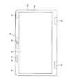
本発明の実施形態に係る粘着部材を適用可能な電子機器としては、例えば図1に示すようなノート型PCが挙げられる。電子機器5は、キーボード装置57を有する機器本体5aと、液晶ディスプレイ等からなるディスプレイ装置51、背面カバー53aおよび正面カバー53bを有する矩形平板状の蓋体5bとを備え、蓋体5bを左右のヒンジ52により機器本体5aに対して開閉可能に連結したクラムシェル型のノート型PCである。[Configuration of electronic equipment]
As an electronic apparatus to which the adhesive member according to the embodiment of the present invention can be applied, for example, a notebook PC as shown in FIG. The
また、電子機器5は、図2に示すように、背面カバー53aと正面カバー53bとの間であって、ディスプレイ装置51の周囲に、カメラ54、無線LAN用アンテナ55およびWiGig用アンテナ56が配置される。本発明の実施形態に係る粘着部材の粘着部材本体10は、後記するように放熱用のサーマルラバーを想定している。そして、粘着部材本体10は、図2に示すように、例えばディスプレイ装置51の周囲に配置されたWiGig用アンテナ56の表面に配置(貼付)され、放熱用部材として用いられる。 In addition, as shown in FIG. 2, the
[粘着部材の構成]
以下、本発明の実施形態に係る粘着部材1の詳細について説明する。粘着部材1は、図3〜図5に示すように、粘着部材本体10と、第1剥離体2と、第2剥離体3と、を備えている。[Configuration of adhesive member]
Hereinafter, the detail of the adhesion member 1 which concerns on embodiment of this invention is demonstrated. As shown in FIGS. 3 to 5, the adhesive member 1 includes an
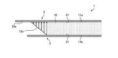
粘着部材本体10は、例えば放熱用のサーマルラバーであり、基材となるシリコン樹脂に導電性微粒子を混合させた導電性シリコン樹脂から構成される。粘着部材本体10は、図4に示すように、両面に粘着面11a,11bを有し、薄いシート状に形成されている。粘着部材本体10は、同図に示すように、図3をX1−X1方向で切断した断面形状が平行四辺形で形成され、図5に示すように、図3をX2−X2方向で切断した断面形状が矩形で形成されている。 The adhesive member
粘着部材本体10の長手方向における2つの端面12a,12bは、図4に示すように、粘着部材本体10の粘着面11a,11bに対して、直角以外の角度で傾斜している。すなわち、粘着部材本体10の一方の端面(第1の端面)12aは、粘着部材本体10の一方の粘着面11aとの間で鋭角θ1を形成しているとともに、粘着部材本体10の他方の粘着面11bとの間で鈍角θ2を形成している。また、粘着部材本体10の他方の端面(第2の端面)12bは、粘着部材本体10の一方の粘着面11aとの間で鈍角θ2を形成しているとともに、粘着部材本体10の他方の粘着面11bとの間で鋭角θ1を形成している。As shown in FIG. 4, the two
ここで、粘着部材本体10の長手方向における2つの端面12a,12bにおける鋭角θ1および鈍角θ2の角度は特に限定されないが、例えば鈍角θ2を100度以上(鋭角θ1を80度以下)とすることが好ましく、鈍角θ2を135度(鋭角θ1を45度)とすることがより好ましい。これにより、後記するように第1剥離体2および第2剥離体3を粘着部材本体10から容易に剥離することができる。なお、図4では、端面12a側の鋭角および鈍角と、端面12b側の鋭角および鈍角とを同じ記号(θ1,θ2)で示しているが、両者の角度はそれぞれ異なっていても構わない。Here, the angles of the acute angle θ1 and the obtuse angle θ2 at the two end faces 12a and 12b in the longitudinal direction of the adhesive member
粘着部材本体10の短手方向における2つの端面13a,13bは、図5に示すように、上記端面12a,12bとは異なり、粘着部材本体10の粘着面11a,11bに対して、直角に形成されている。なお、粘着部材本体10は、例えばトムソン型やビク型の金型を用いた打ち抜き加工によって形成することができる。また、前記したように粘着部材本体10の端面12a,12bを傾斜させるには、例えば粘着部材本体10を構成する材料を金型の動きに合わせて移動させながら打ち抜き加工を行えばよい。 As shown in FIG. 5, the two end faces 13a and 13b in the short direction of the adhesive member
第1剥離体2および第2剥離体3は、作業者が粘着部材本体10を電子機器5の内部機器(例えばWiGig用アンテナ56)に貼り付ける際の利便性の観点から設けられるものであり、例えば樹脂からなる薄い剥離フィルムや、剥離紙等から構成される。第1剥離体2および第2剥離体3は、図4に示すように、粘着面11aおよび粘着面11bにそれぞれ配置されている。また、第1剥離体2および第2剥離体3は、粘着面11a,11bに対応する被粘着面21,31に、例えば離型剤がコーティングされている。 The
第1剥離体2および第2剥離体3は、図4に示すように、粘着部材本体10の長手方向において、粘着部材本体10の端面12a,12bで鈍角θ2が形成された側が、粘着部材本体10の端面12a,12bから突出するように配置されている。すなわち、第1剥離体2は、端面12bの鈍角θ2側が長手方向に長さl2だけ突出した突出部22bを有している。また、第2剥離体3は、端面12aの鈍角θ2側が長手方向に長さl2だけ突出した突出部32bを有している。As shown in FIG. 4, the first peeled
このような構成を備えることにより、突出部22bを把持して粘着面11aから離間する方向に力を加えることにより、第2剥離体3を粘着部材本体10から剥離させることなく、第1剥離体2のみを粘着部材本体10から容易に剥離することができる(後記図7参照)。また、突出部32bを把持して粘着面11bから離間する方向に力を加えることにより、第1剥離体2を粘着部材本体10から剥離させることなく、第2剥離体3のみを粘着部材本体10から容易に剥離することができる。なお、図4では、突出部22bの長さと、突出部32bの長さとを同じ記号(l2)で示しているが、両者の長さはそれぞれ異なっていても構わない。また、第1剥離体2と第2剥離体3のいずれか一方にだけ突出部22bあるいは突出部32bを設けるようにしてもよい。By providing such a configuration, the first peeling body can be held without peeling the second peeling body 3 from the adhesive member
第1剥離体2および第2剥離体3は、図4に示すように、粘着部材本体10の長手方向において、粘着部材本体10の端面12a,12bにおいて鋭角θ1が形成された側が、粘着部材本体10の端面12a,12bから突出するように配置されている。すなわち、第1剥離体2は、端面12bの鋭角θ1側が長手方向に長さl1だけ突出した突出部22aを有している。また、第2剥離体3は、端面12aの鋭角θ1側が長手方向に長さl1だけ突出した突出部32aを有している。As shown in FIG. 4, the first peeled
このような構成を備えることにより、突出部22aを把持して粘着面11aから離間する方向に力を加えることにより、第1剥離体2を粘着部材本体10から剥離させることなく、第2剥離体3のみを粘着部材本体10から容易に剥離することができる(後記図6参照)。また、突出部32aを把持して粘着面11bから離間する方向に力を加えることにより、第2剥離体3を粘着部材本体10から剥離させることなく、第1剥離体2のみを粘着部材本体10から容易に剥離することができる。なお、図4では、突出部22aの長さと、突出部32aの長さとを同じ記号(l1)で示しているが、両者の長さはそれぞれ異なっていても構わない。また、第1剥離体2と第2剥離体3のいずれか一方にだけ突出部22aあるいは突出部32aを設けるようにしてもよい。By providing such a configuration, the second peeled
ここで、第1剥離体2および第2剥離体3は、粘着部材本体10の端面12a,12bにおいて鋭角θ1が形成された側から突出する長さl1と、粘着部材本体10の端面12a,12bにおいて鈍角θ2が形成された側から突出する長さl2とが異なる。すなわち、第1剥離体2および第2剥離体3は、突出部22a,32aの長さl1が突出部22b,32bの長さl2よりも長くなるように構成されている。The first stripping
このような構成を備えることにより、作業者が粘着部材1の粘着部材本体10を電子機器5の内部機器に配置する際に、突出部22a,32aと突出部22b,32bの長さの違いにより、鋭角θ1側と鈍角θ2側とを容易に判別することが可能となる。なお、図4では、突出部22a,32aの長さl1が突出部22b,32bの長さl2よりも長くなるように構成されているが、例えば突出部22a,32aの長さl1が突出部22b,32bの長さl2よりも短くなるように構成しても構わない。By providing such a configuration, when the operator places the adhesive member
また、第1剥離体2および第2剥離体3は、粘着部材本体10の端面12a,12bにおいて鋭角θ1が形成された側と、粘着部材本体10の端面12a,12bにおいて鈍角θ2が形成された側とで異なる形態を有するようにしてもよい。例えば、鋭角θ1が形成された側と鈍角θ2が形成された側とで、第1剥離体2および第2剥離体3の端面や表面の色、模様または形状を変えることができる。このようにすることで、第1剥離体2および第2剥離体3において鋭角θ1が形成された側と鈍角θ2が形成された側とを、見た目や感触で容易に判別できるようになる。第1剥離体2および第2剥離体3は、突出部22a,22b,32a,32bそれぞれの有無に関わらず、このような形態の変化を持たせることができる。Moreover, the
第1剥離体2および第2剥離体3は、図5に示すように、粘着部材本体10の短手方向において、上記長手方向の場合とは異なり、粘着部材本体10の端面13a,13bから突出しておらず、粘着部材本体10と同じ長さ(幅)で構成されている。 As shown in FIG. 5, the
なお、第1剥離体2および第2剥離体3は、粘着部材本体10を例えばトムソン型やビク型の金型を用いて打ち抜き加工して図4および図5に示すような形状に成形した後で、粘着面11a,11bの両面に設けられる。 In addition, the
[粘着部材の貼付手順]
以下、本実施形態に係る粘着部材1の粘着部材本体10を、電子機器5の内部機器であるWiGig用アンテナ56に貼り付ける手順(貼付方法)について説明する。以下では、粘着部材本体10の両面に設けられた第1剥離体2および第2剥離体3をそれぞれ把持部材(ピンセット)Pで把持して剥離し、粘着部材本体10をWiGig用アンテナ56に貼り付ける例について説明する。[Attachment procedure of adhesive material]
Hereinafter, a procedure (sticking method) for sticking the adhesive member
まず、粘着部材本体10から第2剥離体3を剥離する。この場合、図6に示すように、第2剥離体3を作業者の手指等により支持した状態(図示省略)で、把持部材Pによって第1剥離体2の突出部22aを把持して持ち上げる。すると、同図に示すように、第1剥離体2の被粘着面21と粘着部材本体10の粘着面11aとが密着して貼り付いた状態で、粘着部材本体10の粘着面11bと第2剥離体3の被粘着面31とが徐々に離間し、最終的には粘着部材本体10から第2剥離体3が剥離される。そして、第1剥離体2に貼り付いた状態の粘着部材本体10をWiGig用アンテナ56の表面に載置し、把持部材Pによる把持を解除する(図示省略)。 First, the 2nd peeling body 3 is peeled from the adhesion member
このように、本実施形態に係る粘着部材1は、粘着部材本体10の両面に第1剥離体2および第2剥離体3がそれぞれ配置された状態において、図6に示すように、第1剥離体2の突出部22a,22bのうち、粘着部材本体10の鋭角θ1側にある突出部22aを把持して持ち上げることにより、粘着部材本体10から第2剥離体3のみを確実に剥離することができる。As described above, the pressure-sensitive adhesive member 1 according to the present embodiment has the first peel-off as shown in FIG.
一方、図6とは反対に、例えば第1剥離体2の突出部22a,22bのうち、粘着部材本体10の鈍角θ2側にある突出部22bを把持して持ち上げた場合、粘着部材本体10から第1剥離体2のみを確実に剥離することができる。すなわち、本実施形態に係る粘着部材1は、持ち上げる突出部(突出部22aまたは突出部22b)に応じて、剥離する剥離体(第1剥離体2または第2剥離体3)を選択することができる。その原理については後記する(図9〜図12参照)。On the other hand, as opposed to FIG. 6, when, for example, first separating
続いて、粘着部材本体10から第1剥離体2を剥離する。この場合、図7に示すように、把持部材Pによって、図6で把持した突出部22aとは逆側の突出部22bを把持して持ち上げる。すると、同図に示すように、粘着部材本体10の粘着面11bとWiGig用アンテナ56の表面とが貼り付いた状態で、粘着部材本体10の粘着面11aと第1剥離体2の被粘着面21とが徐々に離間し、最終的には粘着部材本体10から第1剥離体2が剥離される。これにより、WiGig用アンテナ56の表面に対する粘着部材本体10の配置が完了する。 Then, the
なお、図6において、例えば第1剥離体2に貼り付いた状態の粘着部材本体10をWiGig用アンテナ56の表面に載置した際に、載置予定位置からずれてしまった場合、図8に示すように、把持部材Pによって第1剥離体2の突出部22aを把持して持ち上げる。すると、同図に示すように、第1剥離体2の被粘着面21と粘着部材本体10の粘着面11aとが密着して貼り付いた状態で、粘着部材本体10の粘着面11bとWiGig用アンテナ56の表面とが徐々に離間し、最終的にはWiGig用アンテナ56の表面から粘着部材本体10が剥離される。これにより、粘着部材本体10をWiGig用アンテナ56の表面における載置予定位置に再度貼り直すことができる。 In FIG. 6, for example, when the adhesive member
[剥離体の剥離の原理]
以下、第1剥離体2および第2剥離体3の剥離の原理について、従来技術と本発明の実施形態との比較を交えて説明する。なお、以下の説明で参照する図9〜図12では、粘着部材1,101の片側半分のみを図示し、残り半分の図示を省略する。[Principle of exfoliation]
Hereinafter, the principle of peeling of the first peeled
従来技術に係る粘着部材101は、例えば図9に示すように、粘着部材本体110の長手方向における端面112aが、粘着部材本体110の粘着面11a,11bに対して直角に形成されている。そのため、粘着部材本体110の端面112a近傍において、粘着部材本体110の強度(粘着部材本体110の厚み方向に働く力に対する強度)が一定となる。 For example, as shown in FIG. 9, the pressure-
従って、従来技術に係る粘着部材101は、図10に示すように、作業者が突出部22aを持ち上げた際に、第1剥離体2と第2剥離体3のどちらが剥離するのか、言い換えると、粘着部材本体110が第1剥離体2と第2剥離体3のどちらに追従するかが分からず、作業者の意図通りに第1剥離体2または第2剥離体3を剥離することが困難である。 Therefore, the
一方、本実施形態に係る粘着部材1は、図11に示すように、粘着部材本体10の長手方向における端面12aが、粘着部材本体10の粘着面11a,11bに対して直角以外の角度に傾斜している。そのため、粘着部材本体10の端面12a近傍において、粘着部材本体10の強度(粘着部材本体10の厚み方向に働く力に対する強度)が一定ではなくなる。すなわち、粘着部材本体10の端面12a近傍において、鋭角θ1側の強度が低くなり、鈍角θ2側の強度が高くなる。On the other hand, as shown in FIG. 11, in the adhesive member 1 according to the present embodiment, the
従って、本発明の実施形態に係る粘着部材1は、図12に示すように、作業者が突出部22aを持ち上げた際に、粘着部材本体10における鋭角θ1側が鈍角θ2側よりも先に変形することにより、第1剥離体2の被粘着面21と粘着部材本体10の粘着面11aとの密着状態が維持される。そして、同図に示すように、粘着部材本体10が第1剥離体2に追従し、粘着部材本体10から第2剥離体3が剥離される。Therefore, the adhesive member 1 according to the embodiment of the present invention, as shown in FIG. 12, when the operator lifts the protruding
以上のように、本実施形態に係る粘着部材1は、粘着部材本体10の2つの対向する端面12a,12bが粘着面11a,11bに対して直角以外の角度に傾斜していることにより、粘着部材本体10の端面12a,12b近傍における強度を変えることができる。従って、粘着部材本体10の粘着面11a,11bに設けられる第1剥離体2および第2剥離体3を容易に、かつ作業者の意図通りに剥離することが可能となる。また、粘着部材1は、貼り直しも容易であるため、リワーク性も向上する。 As described above, the pressure-sensitive adhesive member 1 according to the present embodiment has a pressure-sensitive
以上、本発明に係る粘着部材およびそれを用いた電子機器について、発明を実施するための形態により具体的に説明したが、本発明の趣旨はこれらの記載に限定されるものではなく、特許請求の範囲の記載に基づいて広く解釈されなければならない。また、これらの記載に基づいて種々変更、改変等したものも本発明の趣旨に含まれることはいうまでもない。 As described above, the adhesive member according to the present invention and the electronic device using the same have been specifically described by the embodiments for carrying out the invention. However, the gist of the present invention is not limited to these descriptions, and the claims can be made. Should be interpreted broadly based on the description of the scope. Needless to say, various changes and modifications based on these descriptions are also included in the spirit of the present invention.
例えば、図1および図2では、粘着部材1を適用可能な電子機器5としてノート型PCを例示したが、粘着部材1は、その他にもタブレット型PC、スマートフォンおよび携帯電話等の電子機器5において、放熱が必要な内部機器の表面に配置しても構わない。 For example, in FIG. 1 and FIG. 2, a notebook PC is exemplified as the
また、図1および図2では、粘着部材1の粘着部材本体10をWiGig用アンテナ56の表面に配置した例について説明したが、電子機器5の内部において、放熱が必要な他の内部機器の表面に配置しても構わない。 1 and 2, the example in which the adhesive member
また、本発明の実施形態に係る粘着部材1では、粘着部材本体10として放熱用のサーマルラバーを想定していたが、粘着部材本体10は、例えば電子機器5の内部機器に使用される衝撃吸収ゲルや、フォーム材からなる両面テープ等であっても構わない。 In the pressure-sensitive adhesive member 1 according to the embodiment of the present invention, a thermal rubber for heat dissipation is assumed as the pressure-sensitive adhesive member
また、本発明の実施形態に係る粘着部材1では、粘着部材本体10の長手方向における2つの端面12a,12bを直角以外の角度で傾斜させ、粘着部材本体10の短手方向における2つの端面13a,13bを直角に形成していたが、それとは反対に、端面12a,12bを直角に形成し、端面13a,13bを直角以外の角度で傾斜させても構わない。この場合、第1剥離体2および第2剥離体3は、粘着部材本体10の短手方向において、粘着部材本体10の端面13a,13bから突出するように形成する。 In the pressure-sensitive adhesive member 1 according to the embodiment of the present invention, the two
また、本発明の実施形態に係る粘着部材1では、粘着部材本体10の断面形状が平行四辺形で形成されていたが、端面12aおよび端面12bが、粘着部材本体10の一方の粘着面(粘着面11aまたは粘着面11b)との間で、それぞれ鋭角θ1および鈍角θ2を形成する構成であれば、その他の形状(台形を除く)であっても構わない。Moreover, in the adhesive member 1 which concerns on embodiment of this invention, although the cross-sectional shape of the adhesive member
1,101 粘着部材
10,110 粘着部材本体
11a,11b 粘着面
12a,112a 端面(第1の端面)
12b 端面(第2の端面)
13a,13b 端面
2 第1剥離体
21 被粘着面
22a,22b 突出部
3 第2剥離体
31 被粘着面
32a,32b 突出部
5 電子機器
5a 機器本体
5b 蓋体
51 ディスプレイ装置
52 ヒンジ
53a 背面カバー
53b 正面カバー
54 カメラ
55 無線LAN用アンテナ
56 WiGig用アンテナ
57 キーボード装置
P 把持部材(ピンセット)
θ1 鋭角
θ2 鈍角DESCRIPTION OF SYMBOLS 1,101 Adhesive member 10,110 Adhesive member
12b end face (second end face)
13a,
θ1 acute angle θ2 obtuse angle
Claims (5)
Translated fromJapanese前記粘着部材本体は、
前記粘着部材本体の一方の粘着面との間で鋭角を形成する第1の端面と、
前記第1の端面と対向するとともに、前記一方の粘着面との間で鈍角を形成する第2の端面と、を有し、
前記粘着面に配置された剥離体を備え、
前記剥離体は、前記粘着部材本体の端面において前記鈍角が形成された側が、前記粘着部材本体の端面から突出するように配置され、
前記剥離体は、前記粘着部材本体の端面において前記鋭角が形成された側が、前記粘着部材本体の端面から突出するように配置されていることを特徴とする粘着部材。A sheet-like adhesive member body having an adhesive surface on both sides,
The adhesive member body is
A first end surface forming an acute angle with one adhesive surface of the adhesive member body;
With facing the first end face,I have a, and the second end face forming an obtuse angle between the one adhesivesurface,
Comprising a peeler disposed on the adhesive surface;
The peeled body is arranged such that the side on which the obtuse angle is formed on the end face of the adhesive member main body protrudes from the end face of the adhesive member main body,
The peeling member is arranged such that a side where the acute angle is formed on an end surface of the pressure-sensitive adhesive member main body protrudes from an end surface of the pressure-sensitive adhesive member main body .
前記粘着部材は、両面に粘着面を有するシート状の粘着部材本体を備え、
前記粘着部材本体は、
前記粘着部材本体の一方の粘着面との間で鋭角を形成する第1の端面と、
前記第1の端面と対向するとともに、前記一方の粘着面との間で鈍角を形成する第2の端面と、を有することを特徴とする電子機器。
An electronic device in which an adhesive member is disposed on the surface of an internal device that requires heat dissipation,
The adhesive member comprises a sheet-like adhesive member body having an adhesive surface on both sides,
The adhesive member body is
A first end surface forming an acute angle with one adhesive surface of the adhesive member body;
An electronic apparatus comprising: a second end face that faces the first end face and forms an obtuse angle with the one adhesive face.
Priority Applications (3)
| Application Number | Priority Date | Filing Date | Title |
|---|---|---|---|
| JP2015248642AJP6152409B1 (en) | 2015-12-21 | 2015-12-21 | Adhesive member and electronic device |
| CN201610926088.9ACN106909208B (en) | 2015-12-21 | 2016-10-24 | Adhesive member and electronic device |
| US15/387,044US11079793B2 (en) | 2015-12-21 | 2016-12-21 | Adhesive member for an electronic device |
Applications Claiming Priority (1)
| Application Number | Priority Date | Filing Date | Title |
|---|---|---|---|
| JP2015248642AJP6152409B1 (en) | 2015-12-21 | 2015-12-21 | Adhesive member and electronic device |
Publications (2)
| Publication Number | Publication Date |
|---|---|
| JP6152409B1true JP6152409B1 (en) | 2017-06-21 |
| JP2017114940A JP2017114940A (en) | 2017-06-29 |
Family
ID=59065140
Family Applications (1)
| Application Number | Title | Priority Date | Filing Date |
|---|---|---|---|
| JP2015248642AActiveJP6152409B1 (en) | 2015-12-21 | 2015-12-21 | Adhesive member and electronic device |
Country Status (3)
| Country | Link |
|---|---|
| US (1) | US11079793B2 (en) |
| JP (1) | JP6152409B1 (en) |
| CN (1) | CN106909208B (en) |
Cited By (1)
| Publication number | Priority date | Publication date | Assignee | Title |
|---|---|---|---|---|
| JP3348764B2 (en) | 1996-07-08 | 2002-11-20 | 東京瓦斯株式会社 | Gas flow measurement device |
Families Citing this family (2)
| Publication number | Priority date | Publication date | Assignee | Title |
|---|---|---|---|---|
| JP2020099004A (en)* | 2018-12-18 | 2020-06-25 | レノボ・シンガポール・プライベート・リミテッド | Electronic apparatus |
| JP7320650B1 (en) | 2022-06-17 | 2023-08-03 | レノボ・シンガポール・プライベート・リミテッド | Tape members and electronic equipment |
Family Cites Families (31)
| Publication number | Priority date | Publication date | Assignee | Title |
|---|---|---|---|---|
| JPS4832660U (en)* | 1971-08-23 | 1973-04-20 | ||
| JPS4832660A (en) | 1971-08-26 | 1973-05-01 | ||
| JPH02130920A (en) | 1988-11-11 | 1990-05-18 | Fujitsu Ltd | Manufacturing method of semiconductor device |
| JPH02130920U (en)* | 1989-04-06 | 1990-10-30 | ||
| US5516581A (en)* | 1990-12-20 | 1996-05-14 | Minnesota Mining And Manufacturing Company | Removable adhesive tape |
| US6162534A (en)* | 1998-08-31 | 2000-12-19 | 3M Innovative Properties Company | Stretch release adhesive article with secondary release member |
| US6569521B1 (en)* | 2000-07-06 | 2003-05-27 | 3M Innovative Properties Company | Stretch releasing pressure sensitive adhesive tape and articles |
| US20020090509A1 (en)* | 2001-01-09 | 2002-07-11 | 3M Innovative Properties Company | Electrostatic sheets with adhesive |
| JP2002341770A (en)* | 2001-05-11 | 2002-11-29 | Fuji Photo Film Co Ltd | Pressure sensitive adhesive recording paper |
| CN100414324C (en)* | 2002-10-28 | 2008-08-27 | 日东电工株式会社 | Adhesive optical film, method for producing adhesive optical film and image display device |
| JP4208187B2 (en)* | 2002-10-28 | 2009-01-14 | 日東電工株式会社 | Adhesive optical film, method for producing adhesive optical film, and image display device |
| TWI341983B (en)* | 2003-02-12 | 2011-05-11 | Nissha Printing | Touch panel |
| JP5336050B2 (en)* | 2007-04-06 | 2013-11-06 | 電気化学工業株式会社 | Double-sided adhesive sheet |
| JP5097034B2 (en)* | 2007-07-20 | 2012-12-12 | 日東電工株式会社 | Patches and patch preparations |
| US8546842B2 (en)* | 2009-07-17 | 2013-10-01 | Denki Kagaku Kogyo Kabushiki Kaisha | LED chip assembly, LED package, and manufacturing method of LED package |
| JP4874383B2 (en)* | 2009-12-01 | 2012-02-15 | 日本ゴア株式会社 | A ventilation filter, a method for fixing the ventilation filter, and a method for manufacturing an electric device. |
| JP5731775B2 (en)* | 2010-09-08 | 2015-06-10 | 日東電工株式会社 | Double-sided adhesive tape for fixing flexible printed circuit board and flexible printed circuit board with double-sided adhesive tape |
| JP5858469B2 (en)* | 2011-01-28 | 2016-02-10 | サン・トックス株式会社 | Release film-bonded double-sided PSA sheet and method for producing the same |
| JP2013067751A (en)* | 2011-09-26 | 2013-04-18 | Dainippon Printing Co Ltd | Optical film and image display |
| JP6081123B2 (en)* | 2011-10-08 | 2017-02-15 | 三菱樹脂株式会社 | Substrate-less double-sided adhesive sheet |
| JP2012077305A (en)* | 2011-11-07 | 2012-04-19 | Hitachi Chemical Co Ltd | Film for anisotropically conductive connection and reel body |
| KR20130096094A (en)* | 2012-02-21 | 2013-08-29 | 엘지이노텍 주식회사 | Light emitting device package, manufactueing method for light emitting device pacakge and lighting system having light emitting device package |
| KR101511284B1 (en)* | 2012-06-04 | 2015-04-10 | 주식회사 아모그린텍 | A conductive pressure-sensitive adhesive tape and preparation method thereof |
| CN202826604U (en)* | 2012-07-26 | 2013-03-27 | 广州市华宇化工有限公司 | Non-stick membrane |
| JP2014086967A (en)* | 2012-10-25 | 2014-05-12 | Toshiba Corp | Electronic device |
| US20150299524A1 (en)* | 2012-11-30 | 2015-10-22 | Lintec Corporation | Adhesive agent composition, adhesive sheet, and electronic device |
| CN105121578B (en)* | 2013-03-05 | 2018-03-09 | 日东电工株式会社 | Adhesive layer, adhesive tape, and double-sided adhesive tape |
| JP2014232221A (en)* | 2013-05-29 | 2014-12-11 | 船井電機株式会社 | Electronic apparatus |
| US20150171504A1 (en)* | 2013-12-13 | 2015-06-18 | Kabushiki Kaisha Toshiba | Electronic apparatus |
| US20150218425A1 (en)* | 2014-02-05 | 2015-08-06 | Apple Inc. | Stretch release conductive adhesive |
| JP6423781B2 (en)* | 2015-11-20 | 2018-11-14 | 株式会社ジャパンディスプレイ | Display device |
- 2015
- 2015-12-21JPJP2015248642Apatent/JP6152409B1/enactiveActive
- 2016
- 2016-10-24CNCN201610926088.9Apatent/CN106909208B/enactiveActive
- 2016-12-21USUS15/387,044patent/US11079793B2/enactiveActive
Cited By (1)
| Publication number | Priority date | Publication date | Assignee | Title |
|---|---|---|---|---|
| JP3348764B2 (en) | 1996-07-08 | 2002-11-20 | 東京瓦斯株式会社 | Gas flow measurement device |
Also Published As
| Publication number | Publication date |
|---|---|
| US11079793B2 (en) | 2021-08-03 |
| JP2017114940A (en) | 2017-06-29 |
| CN106909208B (en) | 2021-01-12 |
| CN106909208A (en) | 2017-06-30 |
| US20170177028A1 (en) | 2017-06-22 |
Similar Documents
| Publication | Publication Date | Title |
|---|---|---|
| JP6152409B1 (en) | Adhesive member and electronic device | |
| TWI464487B (en) | Electronic apparatus and method for removing protection film thereof | |
| CN112140523A (en) | Screen protector assemblies and applicators for screen protectors | |
| MY190282A (en) | Tape for electronic device packaging | |
| JP3205666U (en) | Film sticking tool | |
| JP2006206782A (en) | Functional film for attaching flat display and method of attaching the same | |
| CN203359160U (en) | Easy-to-stick protective film for electronic devices | |
| WO2013005584A1 (en) | Rfid inlet antenna and rfid employing same | |
| JP5142367B2 (en) | Thin film thermal diffusion sheet | |
| CN112226170B (en) | Secret sticker | |
| JP5857202B2 (en) | Heat conduction sheet | |
| CN204223463U (en) | Display panel protective film | |
| JP6469425B2 (en) | Electronics | |
| US8998622B2 (en) | Electrical connectors with applicators for electronic devices | |
| EP3428241B1 (en) | Stretch release adhesive, battery assembly and housing assembly | |
| TW201431698A (en) | Protective film structure and method of application thereof | |
| JP3193806U (en) | Protective material sticker on the liquid crystal surface of mobile devices | |
| JP2013107996A (en) | Display screen protection sheet used for information mobile terminal | |
| JP2014065852A (en) | Protective film with protective material | |
| JP5685746B2 (en) | Attached sheet | |
| JP2015513697A (en) | label | |
| CN216946833U (en) | Nanometer heat dissipation copper foil | |
| CN220570556U (en) | Back cover and electronic equipment | |
| JP4257915B2 (en) | Method for producing insulating thin film body | |
| CN219740709U (en) | A cable stress buffer, soft cable structure and interactive flat panel |
Legal Events
| Date | Code | Title | Description |
|---|---|---|---|
| TRDD | Decision of grant or rejection written | ||
| A01 | Written decision to grant a patent or to grant a registration (utility model) | Free format text:JAPANESE INTERMEDIATE CODE: A01 Effective date:20170509 | |
| A61 | First payment of annual fees (during grant procedure) | Free format text:JAPANESE INTERMEDIATE CODE: A61 Effective date:20170529 | |
| R150 | Certificate of patent or registration of utility model | Ref document number:6152409 Country of ref document:JP Free format text:JAPANESE INTERMEDIATE CODE: R150 | |
| S111 | Request for change of ownership or part of ownership | Free format text:JAPANESE INTERMEDIATE CODE: R313113 | |
| R350 | Written notification of registration of transfer | Free format text:JAPANESE INTERMEDIATE CODE: R350 | |
| R250 | Receipt of annual fees | Free format text:JAPANESE INTERMEDIATE CODE: R250 | |
| R250 | Receipt of annual fees | Free format text:JAPANESE INTERMEDIATE CODE: R250 | |
| R250 | Receipt of annual fees | Free format text:JAPANESE INTERMEDIATE CODE: R250 | |
| R250 | Receipt of annual fees | Free format text:JAPANESE INTERMEDIATE CODE: R250 | |
| R250 | Receipt of annual fees | Free format text:JAPANESE INTERMEDIATE CODE: R250 | |
| S111 | Request for change of ownership or part of ownership | Free format text:JAPANESE INTERMEDIATE CODE: R313113 | |
| R250 | Receipt of annual fees | Free format text:JAPANESE INTERMEDIATE CODE: R250 | |
| R350 | Written notification of registration of transfer | Free format text:JAPANESE INTERMEDIATE CODE: R350 |