JP6152026B2 - Coating apparatus and stent manufacturing method - Google Patents
Coating apparatus and stent manufacturing methodDownload PDFInfo
- Publication number
- JP6152026B2 JP6152026B2JP2013197305AJP2013197305AJP6152026B2JP 6152026 B2JP6152026 B2JP 6152026B2JP 2013197305 AJP2013197305 AJP 2013197305AJP 2013197305 AJP2013197305 AJP 2013197305AJP 6152026 B2JP6152026 B2JP 6152026B2
- Authority
- JP
- Japan
- Prior art keywords
- rotating body
- chamber
- workpiece
- stent
- rotating
- Prior art date
- Legal status (The legal status is an assumption and is not a legal conclusion. Google has not performed a legal analysis and makes no representation as to the accuracy of the status listed.)
- Active
Links
Images


Landscapes
- Materials For Medical Uses (AREA)
- Physical Vapour Deposition (AREA)
Description
Translated fromJapanese本発明は、コーティングを施そうとする金属製のワークに、蒸着することでポリマーをコーティングするためのコーティング装置およびワークであるステントを製造するステント製造方法に関する。 The present invention relates to a coating apparatus for coating a polymer by vapor deposition on a metal workpiece to be coated, and a stent manufacturing method for manufacturing a stent which is a workpiece.
蒸着プロセスによってコーティングしようとするワイヤ物品をコーティングする装置が、特許文献1に提案されている。特許文献1の図2、図3に示すように、このコーティング装置は、円筒のコーティングチャンバ(14)を有しており、このコーティングチャンバの中には、回転駆動される円筒の可動セルタンブルコータ(11)が配置されている。
この可動セルタンブルコータとコーティングチャンバの間には、複数の円筒でなり、内部にワークであるワイヤ部品を多数一緒に充填収容するための可動部分セル(12)が配置されており、この可動部分セル(12)は多数の穴を有している。この可動セルタンブルコータ(11)と共に複数の可動部分セル(12)が、コーティングチャンバ(14)内で回転するようになっている。An apparatus for coating a wire article to be coated by a vapor deposition process is proposed in Patent Document 1. As shown in FIGS. 2 and 3 of Patent Document 1, this coating apparatus has a cylindrical coating chamber (14), and in this coating chamber, a cylindrical movable cell tumble coater that is driven to rotate. (11) is arranged.
Between the movable cell tumble coater and the coating chamber, a movable part cell (12) is provided, which is composed of a plurality of cylinders and is filled and accommodated with a large number of wire parts as workpieces. The cell (12) has a number of holes. A plurality of movable partial cells (12) together with the movable cell tumble coater (11) rotate in the coating chamber (14).
コーティングチャンバ(14)内で気化したパリレン(パリレン:日本パリレン合同会社の登録商標)は、昇温によりパリレンモノマー蒸気となり、このパリレンモノマー蒸気は、コーティングチャンバ(14)内の真空条件下で導入され、可動部分セル(12)の穴を通過して可動部分セル内のワイヤ部品に触れる。これにより、ワイヤ部品には、蒸着プロセスによってポリマーをコーティングできるようになっている。 Parylene vaporized in the coating chamber (14) (Parylene: a registered trademark of Japan Parylene Godo Kaisha) becomes parylene monomer vapor when heated, and this parylene monomer vapor is introduced under vacuum conditions in the coating chamber (14). Then, the wire part in the movable part cell is touched through the hole of the movable part cell (12). As a result, the wire part can be coated with the polymer by a vapor deposition process.
ところが、上述した特許文献1に記載の装置では、各可動部分セル内には多数のワイヤ部品が密着状態で充填されているので、ワークである多数のワイヤ部品は、互いに位置を変えながら、常にワークどうしで接触していて、個々のワイヤ部品の外面が、パリレンモノマー蒸気に確実に暴露されない。このため、各ワイヤ部品に対するパリレンのポリマーのコーティングが確実に行えないことがある。
しかも、各可動部分セルをコーティングチャンバの内部で回転移動させるので、可動部分セル内に充填されている各ワイヤ部品が相互に衝突する。このため、各ワイヤ部品からポリマー被膜が剥がれてしまうおそれがある。このため、ワイヤ部品に対するポリマーのコーティング処理の効率を上げることができない。However, in the apparatus described in Patent Document 1 described above, each movable part cell is filled with a large number of wire parts in close contact with each other. In contact between workpieces, the outer surfaces of the individual wire parts are not reliably exposed to the parylene monomer vapor. For this reason, the parylene polymer coating may not be reliably performed on each wire part.
In addition, since each movable part cell is rotationally moved inside the coating chamber, the wire parts filled in the movable part cell collide with each other. For this reason, there exists a possibility that a polymer film may peel from each wire component. For this reason, the efficiency of the coating process of the polymer with respect to a wire part cannot be raised.
そこで、本発明は、個々のワークの外面が確実に蒸着気体に露出されるようにして、しかもワークからパリレンのようなポリマー被膜の剥がれを無くして、ワークのコーティング処理の効率を上げることができるコーティング装置と、ワークであるステントにパリレンのようなポリマー被膜を形成してポリマー被膜の剥がれを無くして、ステントのコーティング処理の効率を上げることができるステント製造方法を提供することを目的とする。 Therefore, the present invention can increase the efficiency of the coating process of the workpiece by ensuring that the outer surface of each workpiece is exposed to the vapor deposition gas, and also eliminating the peeling of the polymer film such as parylene from the workpiece. It is an object of the present invention to provide a coating apparatus and a stent manufacturing method capable of improving the efficiency of stent coating treatment by forming a polymer film such as parylene on a stent as a workpiece to eliminate peeling of the polymer film.
本発明のコーティング装置は、ワークをチャンバ内に収容して前記チャンバ内にモノマーガスを通すことで、モノマーの重合によりできるポリマーを前記ワークに蒸着してコーティングするコーティング装置であって、前記チャンバ内には、複数個の前記ワークを保持するワーク保持装置が配置されており、前記ワーク保持装置は、前記チャンバ内で回転可能に配置されている回転部と、前記回転部の回転中心よりも離れた箇所に、相互に間隔をおいて設けられている複数のワーク支持体とを備えており、前記回転部は、第1回転体と、該第1回転体と対向して配置された第2回転体とを有しており、前記第1回転体の一つの平面には、該平面に対して垂直に起立するように前記複数のワーク支持体が相互に間隔をおいて固定され、前記第2回転体の一つの平面には、該平面に対して垂直に起立するように前記複数のワーク支持体が相互に間隔をおいて固定され、前記第1回転体の前記平面と前記第2回転体の前記平面は、互いに反対方向に向いている面であり、前記各ワーク支持体が前記ワークを保持した状態において、前記ワーク同士の間には隙間を形成する構成としたことを特徴とする。
上記構成によれば、回転部の回転中心よりも離れた箇所に、相互に間隔をおいて設けられている複数のワーク支持体を有している。そして、前記各ワーク支持体が前記ワークを保持した状態において、前記ワーク同士の間には隙間を形成する構成とされている。
このため、チャンバ内にモノマーガスを通し、回転部をチャンバ内で回転させることにより、モノマーが重合してできるポリマーを個々のワークの外面に均一かつ確実にモノマーガスが触れることが可能とされる。特に、ワーク同士が重なりあったり、互いに衝突したりすることが無いので、ワークからポリマー被膜の剥がれを無くして、ワークのコーティング処理の効率を上げることができる。The coating apparatus of the present invention is a coating apparatus that deposits and coats a polymer formed by polymerization of a monomer on the workpiece by housing the workpiece in a chamber and passing a monomer gas through the chamber. Is provided with a work holding device for holding a plurality of the workpieces, the work holding device being spaced apart from a rotating part rotatably arranged in the chamber from a rotation center of the rotating part. A plurality of work supports provided at intervals from each other, and therotating portion includes a first rotating body and a second rotating body disposed opposite to the first rotating body. A plurality of work supports are fixed to one plane of the first rotator at a distance from each other so as to stand perpendicular to the plane; 2 The plurality of workpiece supports are fixed to one plane of the rolling body so as to stand perpendicularly to the plane, and the plane of the first rotating body and the second rotating body are fixed. The planes are surfaces facing in opposite directions to each other, and in a state in which each work support holds the work, a gap is formed between the works.
According to the said structure, it has the some workpiece | work support body provided in the location away from the rotation center of the rotation part at intervals. And in the state which each said workpiece | work support body hold | maintained the said workpiece | work, it is set as the structure which forms a clearance gap between the said workpiece | work.
For this reason, by passing the monomer gas through the chamber and rotating the rotating part in the chamber, the monomer gas can be uniformly and surely touched to the outer surface of each workpiece by polymerizing the monomer. . In particular, since the workpieces do not overlap or collide with each other, peeling of the polymer film from the workpiece can be eliminated and the efficiency of the workpiece coating process can be increased.
上記構成によれば、回転部の第1回転体と第2回転体とは、対向して配置されているので、前記回転部が1つの回転体を有する場合に比べて、該回転部が回転する際には、バランス良く回転させることができる。しかも、前記回転部に設けることができる前記ワーク支持体の数を増やすことができるので、保持できる前記ワークの数を増やして、これらワークのコーティング処理の効率を上げることができる。According tothe above Symbol configuration, the first rotating body of the rotating part and the second rotating body, since it is arranged opposite, in comparison with the case where the rotating section has one of the rotating body, the rotating part When rotating, it can be rotated with good balance. And since the number of the said workpiece | work support bodies which can be provided in the said rotation part can be increased, the number of the said workpiece | work which can be hold | maintained can be increased and the efficiency of the coating process of these workpiece | work can be raised.
上記構成によれば、第1回転体においてワーク支持体が取り付けられている面と、第2回転体においてワーク支持体が取り付けられている面が、反対方向の面である。このため、駆動機構部は第1回転体と第2回転体の間に容易に設けることができる。According tothe above Symbol configuration, to a plane workpiece support is mounted in a first rotary member, the surface on which the workpiece support is mounted at the second rotating body is a surface opposite directions. For this reason, a drive mechanism part can be easily provided between a 1st rotary body and a 2nd rotary body.
また、本発明のステント製造方法は、複数のワークであるステントをチャンバ内に収容して前記チャンバ内にモノマーガスを通すことで、前記ステントにポリマーをコーティングするステント製造方法であって、前記チャンバ内に配置されているワーク保持装置の回転部には複数のワーク支持体が設けられており、前記複数のワークをそれぞれ前記チャンバ内に入れて前記ステントを前記ワーク支持体に、前記複数のワークどうしの間に隙間をつくるように保持し、前記回転部は、第1回転体と、該第1回転体と対向して配置された第2回転体とを有しており、前記第1回転体の一つの平面には、該平面に対して垂直に起立するように前記複数のワーク支持体が相互に間隔をおいて固定され、前記第2回転体の一つの平面には、該平面に対して垂直に起立するように前記複数のワーク支持体が相互に間隔をおいて固定され、前記第1回転体の前記平面と前記第2回転体の前記平面は、互いに反対方向に向いている面であり、前記回転部を前記チャンバ内で回転しながら、前記チャンバ内に前記モノマーガスを通すことで、モノマーの重合によりできるポリマーを前記ステントに蒸着してコーティングすることを特徴とする。
上記構成によれば、回転部に固定されているワーク支持体を各ステント内に通すことで各ステントはワーク支持体に保持し、そしてチャンバ内にモノマーガスを通し、回転部をチャンバ内で回転させることにより、モノマーの重合によりできるポリマーがステントに均一に被膜を形成することができる。ワーク支持体は、相互に間隔をおいて回転部に固定されており、ワーク支持体を各ステント内に通すことで各ステントはワーク支持体に保持しているので、各ステントにはモノマーガスが行き渡り、回転部が回転してもステント同士は衝突することが無い。これにより、ステントからポリマー被膜の剥がれを無くして、ワークのコーティング処理の効率を上げることができる。The stent manufacturing method of the present invention is a stent manufacturing method in which a stent is coated with a polymer by accommodating a plurality of workpieces in a chamber and passing a monomer gas through the chamber. A plurality of work supports are provided in the rotating portion of the work holding device disposed inside, and the plurality of works are respectively placed in thechamber so that the stent is used as the work support. Therotating part has a first rotating body and a second rotating body arranged to facethe first rotating body, and the first rotating body holdsthe first rotating body. The plurality of workpiece supports are fixed to one plane of the body at a distance from each other so as to stand perpendicularly to the plane, and the one plane of the second rotating body is fixed to the plane. Against The plurality of workpiece supports are fixed to each other so as to stand vertically, and the plane of the first rotating body and the plane of the second rotating body are surfaces facing in opposite directions to each other. There, while rotating the rotating part in the chamber, by passing the monomer gas into the chamber, and wherein the coating the polymers can by polymerization of the monomers deposited on the stent.
According to the above configuration, each stent is held on the work support by passing the work support fixed to the rotating part through each stent, and monomer gas is passed through the chamber, and the rotating part is rotated in the chamber. By doing so, a polymer formed by polymerization of monomers can form a uniform coating on the stent. The work supports are fixed to the rotating part at intervals, and each stent is held on the work support by passing the work support through each stent. Even if the rotation part rotates, the stents do not collide with each other. Thereby, peeling of a polymer film from a stent can be eliminated and the efficiency of the coating process of a workpiece | work can be raised.
本発明は、個々のワークの外面が確実に蒸着気体に露出されるようにして、しかもワークからパリレンのようなポリマー被膜の剥がれを無くして、ワークのコーティング処理の効率を上げることができる。 According to the present invention, the outer surface of each workpiece can be surely exposed to the vapor deposition gas, and the polymer coating such as parylene can be removed from the workpiece to increase the efficiency of the coating process of the workpiece.
以下に、本発明の好ましい実施形態を、図面を参照して詳しく説明する。
尚、以下に述べる実施の形態は、本発明の好適な具体例であるから、技術的に好ましい種々の限定が付されているが、本発明の範囲は、以下の説明において特に本発明を限定する旨の記載がない限り、これらの態様に限られるものではない。
図1は、本発明のコーティング装置の好ましい実施形態を示す図である。
図1に示すコーティング装置1は、コーティング処理の対象物(以下では、ワークという)である金属製のステントの面に対して、蒸着プロセスによりパリレンのモノマーガスを供給することにより、モノマーが重合したパリレンを蒸着させる装置である。Hereinafter, preferred embodiments of the present invention will be described in detail with reference to the drawings.
The embodiments described below are preferred specific examples of the present invention, and thus various technically preferable limitations are given. However, the scope of the present invention is particularly limited in the following description. Unless otherwise stated, the present invention is not limited to these embodiments.
FIG. 1 is a view showing a preferred embodiment of the coating apparatus of the present invention.
The coating apparatus 1 shown in FIG. 1 polymerizes a monomer by supplying parylene monomer gas to the surface of a metal stent, which is an object to be coated (hereinafter referred to as a workpiece), by a vapor deposition process. It is an apparatus for vapor deposition of parylene.
このパリレンは、日本パリレン合同会社の登録商標であり、パラキシリレン系ポリマーを意味し、ベンゼン環がCH2を介してつながった構造をもっている。重合したパラキシリレンは分子量が50万にもおよぶ非常に安定した結晶性ポリマーである。パリレンには幾つかの種類があるが、本発明の実施形態では、パリレンとしては、特に好ましくはパリレンCが用いられる。このパリレンCを用いる理由は、パリレンCはポリマーとして、より安定している物質であるためである。パリレンNはパリレンの基本となり、パリレンCは、パリレンNのベンゼン環の水素1つを塩素(Cl)で置き換えた構造を持っており、電気特性と物理特性のバランスが良く、かつ高いバリア性を持っている。
本発明の実施形態においては、以下の説明では、パリレンCを単にパリレンという。This parylene is a registered trademark of Japan Parylene LLC, means a paraxylylene-based polymer, and has a structure in which benzene rings are connected via CH2 . Polymerized paraxylylene is a very stable crystalline polymer having a molecular weight of up to 500,000. There are several types of parylene. In the embodiment of the present invention, parylene C is particularly preferably used as parylene. The reason for using this parylene C is that parylene C is a more stable substance as a polymer. Parylene N is the basis of parylene, and parylene C has a structure in which one hydrogen in the benzene ring of parylene N is replaced with chlorine (Cl), providing a good balance between electrical and physical properties and high barrier properties. have.
In the embodiment of the present invention, parylene C is simply referred to as parylene in the following description.
図1に示すコーティング装置1は、処理炉2と、チャンバ3と、チラートラップ4と、真空ポンプ5と、制御部100を有している。処理炉2とチャンバ3は、配管7により接続され、チャンバ3とチラートラップ4は、配管8により接続されている。チャンバ3の内部は、配管8とチラートラップ4を介して、真空引きされるようになっている。制御部100は、バルブ8aにより配管8を開閉制御できるようになっている。
図1に示す処理炉2は、気化炉と熱分解室を有している。処理炉2の気化炉は、パリレンの原料ポリマーを、好ましくは50℃から125℃の温度で加熱して気化させる。処理炉2の熱分解室は、気化させたパリレンの原料ポリマーを、例えば680℃に加熱させて分解させることで、反応性に富んだパリレンのモノマーガスを生成させることができるようになっている。A coating apparatus 1 shown in FIG. 1 includes a processing furnace 2, a chamber 3, a chiller trap 4, a vacuum pump 5, and a
The processing furnace 2 shown in FIG. 1 has a vaporization furnace and a thermal decomposition chamber. The vaporization furnace of the processing furnace 2 heats and vaporizes the parylene raw material polymer at a temperature of preferably 50 ° C to 125 ° C. The thermal decomposition chamber of the processing furnace 2 can generate a parylene monomer gas rich in reactivity by heating and decomposing the vaporized parylene raw polymer to, for example, 680 ° C. .
図1に示す処理炉2とこれに続くチャンバ3等の図示の系全体は真空であり、チャンバ3には真空計6が設けられている。この真空のチャンバ3内には、処理炉2から配管7を介して上述したパリレンのモノマーガスが導入される。このパリレンのモノマーガスは、チャンバ3内において、ワークであるステントの表面で重合させることで、分子量が50万にも及ぶ高分子のポリパラキシリレンの被膜、すなわちパリレンのポリマー被膜を、ステントの表面に形成させることができるようになっている。 The entire illustrated system such as the processing furnace 2 shown in FIG. 1 and the subsequent chamber 3 is in a vacuum, and the chamber 3 is provided with a vacuum gauge 6. The above-described parylene monomer gas is introduced into the vacuum chamber 3 from the processing furnace 2 through the
図1に示す処理炉2は、制御部100の制御により、昇温される。パリレン(パリレンC)は原料ポリマーパウダーとして、より安定している。好ましくは50℃から125℃の温度に保持されたパリレンの原料ポリマーパウダーを、処理炉3の投入口から投入すると、原料ポリマーパウダーは、処理炉2の熱分解室で昇温することにより、少しずつ気化されて、好ましくは680℃で反応性に富んだパリレンのモノマーガスに分解される。 The processing furnace 2 shown in FIG. 1 is heated by the control of the
このモノマーガスに分解されたパリレンは、配管7を介して真空のチャンバ3内に送られるようになっている。チャンバ3内の雰囲気の真空度は、真空計6によりモニタしており、その真空度の情報は制御部100に送られる。
後で詳しく説明するが、このチャンバ3内には、複数個のステントが収容されている。チャンバ3内では、パリレンのモノマーガスが通過することで、パリレンのモノマーガスを、常温でポリマーに変えて、各ステントには、パリレンのポリマー被膜を堆積させることができるようになっている。The parylene decomposed into the monomer gas is sent into the vacuum chamber 3 through the
As will be described in detail later, a plurality of stents are accommodated in the chamber 3. The parylene monomer gas passes through the chamber 3, so that the parylene monomer gas is changed into a polymer at room temperature, and a parylene polymer film can be deposited on each stent.
図1に示すチラートラップ4は、チャンバ3と真空ポンプ5の間に配置されている。このチラートラップ4は、チャンバ3内で、ステントにポリマー被膜として堆積せずに通過したパリレンのモノマーガスを堆積させることで捕獲する。これにより、チラートラップ4は、ポリマー被膜として堆積しなかったパリレンのモノマーガスが、真空ポンプ5側に行かないように捕獲することで、真空ポンプ5を保護する。 The chiller trap 4 shown in FIG. 1 is disposed between the chamber 3 and the vacuum pump 5. The chiller trap 4 captures the chamber 3 by depositing the parylene monomer gas that has passed without being deposited as a polymer film on the stent. Thus, the chiller trap 4 protects the vacuum pump 5 by capturing the parylene monomer gas that has not been deposited as a polymer film so as not to go to the vacuum pump 5 side.
次に、図1に示すチャンバ3の好ましい構造例を、図2と図3を参照して、説明する。
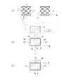
図2は、図1に示すチャンバ3の構造例を示している。図3は、図2に示すチャンバ3の容器11内に配置されているワーク保持装置20の構造例を示す図である。
図2に示すように、チャンバ3は、容器11と、整流板12,13と、蓋部材14と、ワーク保持装置20を有している。Next, a preferred structural example of the chamber 3 shown in FIG. 1 will be described with reference to FIGS.
FIG. 2 shows an example of the structure of the chamber 3 shown in FIG. FIG. 3 is a view showing a structural example of the
As shown in FIG. 2, the chamber 3 includes a container 11,
図1と図2に示すように、容器11は、底部15を有する円筒型の部材であり、容器11は、上端部の円形の開口部16を有している。この開口部16は、蓋部材14により着脱可能に気密に閉じることで、容器11内は真空状態に保持できる。
図1に示すように、この容器11は、上流側の開口部11Aと下流側の開口部11Bを有している。上流側の開口部11Aには配管7が接続され、下流側の開口部11Bには配管8が接続されている。As shown in FIGS. 1 and 2, the container 11 is a cylindrical member having a bottom 15, and the container 11 has a
As shown in FIG. 1, this container 11 has an
図3に示すワーク保持装置20は、図2に示す矢印G方向から見た様子を示している。図2と図3に示すワーク保持装置20は、回転部60を有している。この回転部60は、容器11内に収容されている。この回転部60は、複数の回転体を有していて、本実施形態では、例えば、第1回転体21と、第2回転体22を有している。
さらに、図3に示すように、ワーク保持装置20は、カバー部材23と、カバー部材24と、駆動モータ25と、駆動機構部26と、減速機27を有している。図3に示すように、カバー部材23とカバー部材24と駆動機構部26は、チャンバ3内に配置されているが、駆動モータ25と減速機27は、チャンバ3の外側に配置されている。カバー部材24は、回転部60とカバー部材23と駆動機構部26をチャンバ3の底部15に対して支える支柱でもある。The
Furthermore, as shown in FIG. 3, the
図2と図3に示すように、カバー部材23は、例えば断面円形の筒部材であり、第1回転体21は、カバー部材23の一端部側に位置され、第2回転体22は、カバー部材23の他端部側に位置されている。
第1回転体21と第2回転体22は、共に同じ大きさを有する、例えばSUS製の円盤である。第1回転体21の外面21Aには、第1回転体21外面に複数本のワーク支持体30が外面21Aに対して垂直に、かつ、相互に間隔をおいて突出するように固定されている。同様にして、第2回転体22の外面22Aには、第2回転体22の外面22Aに対して垂直に多数のワーク支持体30が相互に間隔をおいて突出するように固定されている。
第1回転体21の外面21Aと第2回転体22の外面22Aは、反対側に向いている面であり、それぞれの複数本のワーク支持体30は、互いに反対方向に向けて水平に突出している。このワーク支持体30は、好ましくは断面円形のピンあるいは芯金である。As shown in FIGS. 2 and 3, the
The
The
このように、回転部60の第1回転体21と第2回転体22は、対向して配置されているので、回転部が1つの回転体を有する場合に比べて、回転部60が回転する際には、バランス良く回転させることができる。第1回転体21と第2回転体22を備えることで、回転部60に設けることができるワーク支持体30の数を増やすことができることから、保持できるワークの数を増やして、ワークのコーティング処理の効率を上げることができる。 Thus, since the 1st
また、第1回転体21においてワーク支持体30が取り付けられている面21Aと、第2回転体22においてワーク支持体30が取り付けられている面22Aが、反対方向の面であるので、複数のワーク支持体30の存在に影響を受けずに、駆動機構部26は第1回転体21と第2回転体22の間に容易に設けることができる。 Moreover, since the
図2と図3に示すように、複数本のワーク支持体30には、それぞれワークとしてのステントWを着脱可能に取り付けることができる。各ワーク支持体30は、各回転体の外面にどのように立設されてもよいが、生産効率を考慮すると、好ましくは、第1回転体21と第2回転体22の各外面において、当該外面の面積を埋め尽くすように多数設けられている。
例えば、ワーク支持体30が棒体である場合(その断面形状は円形に限らない。)、ワーク支持体30の直径は、挿通されるステントWの内径に比べてかなり小さくされており、挿通時の作業に支障が出るほど互いの直径の値が近くなく、かつ挿通後(装着後)は各回転体の動きにより容易に脱落しない程度にステントWが緩く拘束されるようにされている。
また、各回転体の外面において、ワーク支持体30はできるだけ多く立設されているが、互いの間隔はワークであるステントWの直径を超える寸法とされることで、回転体が動きながら後述する蒸着工程を実行する際に、隣り合うステントWが触れあわないようにされている。As shown in FIGS. 2 and 3, a stent W as a workpiece can be detachably attached to the plurality of workpiece supports 30. Each
For example, when the
Further, as many
図3には、駆動機構部26を示している。この駆動機構部26は、回転軸33,34と、歯車35,36を有している。回転軸33は、第1回転体21と第2回転体22の回転中心CLに沿って水平方向に配置されており、回転軸33はカバー部材23により覆われている。回転軸33の一端部は、第1回転体21の中心位置に固定され、回転軸33の他端部は、第2回転体22の中心位置に固定されている。これにより、回転軸33と第1回転体21と第2回転体22は、カバー部材23に支えられて、回転中心CLを中心にして回転可能になっている。 FIG. 3 shows the
図3に示す回転軸34は、垂直方向に配置されており、回転軸34はカバー部材24により覆われている。歯車35は回転軸33の中間位置に固定され、歯車36は回転軸34の上端部に固定されている。歯車35と歯車36が噛み合っており、回転軸34の回転は、歯車35,36により、回転軸33の回転に変換できる。
このように、チャンバ3内では、駆動機構部26の回転軸33,34と歯車35,36は、カバー部材23,24により覆われているので、回転軸33,34と歯車35,36にはパリレンのポリマー被膜が形成されてしまうことが無いので、駆動機構部26の動作に影響がでない。The rotating
Thus, in the chamber 3, the
回転軸34の下端部は、減速機27の出力軸37に連結されている。駆動モータ25の出力軸は減速機27に連結されている。制御部100が駆動モータ25に指令を与えることにより、駆動モータ25の出力軸の回転は、減速機27により減速されたのちに、減速機27の出力軸37を介して回転軸34の回転になる。回転軸34の回転は、歯車35,36を介して回転軸33の回転に変えることができる。これにより、回転部60の第1回転体21と第2回転体22は、回転中心CLを中心にして、所定の回転数で矢印R方向に連続回転させることができる。
The lower end of the
図2に示すように、整流板12は、容器11の上流側の開口部11Aの付近において、上流側の開口部11Aと、ワーク保持装置20との間に配置されている。もう1つの整流板13は、容器11の下流側の開口部11Bの付近において、下流側の開口部11Bと、ワーク保持装置20との間に配置されている。すなわち、整流板12は、パリレンのモノマーガスの流れの上流側に配置され、整流板13は、パリレンのモノマーガスの流れの下流側に配置されている。
図2に示すように、これらの整流板12,13は、それぞれ例えばパンチングメタル板であり、複数個の貫通穴Hを有している。整流板12,13の複数の貫通穴Hの形成領域は、好ましくは、第1回転体21と第2回転体22に装着されている複数個のステントWに対してパリレンのモノマーガスを集中的に案内しながら効率良く流すことができるように設定されている。As shown in FIG. 2, the
As shown in FIG. 2, these rectifying
これにより、図2に例示するように、整流板12,13の複数の貫通穴Hは、パリレンのモノマーガスの流れを矢印Fで示すように作り出して、第1回転体21と第2回転体22に装着されている複数個のステントWに対してパリレンのモノマーガスを集中的に誘導することができる。
そして、このモノマーガスは、複数本のワーク支持体30が回転体の外面21Aに対して垂直に、かつ、相互に間隔をおいて突出するように固定されている支持体に保持されたワークとしてのステントWの露出された表面に行きわたる。つまり、ワークは互いに重なり合い、密着して、一部の表面を覆うことがないので、パリレンのモノマーガスに対して完全に暴露される。これにより均一なコーティングがむらなく形成される。
図4(A)は、ワークであるステントWの形状例を示している。このステントWは、金属パイプを所定のデザイン(例えば図3のデザイン)に沿ってレーザーカットし、研磨・焼鈍することで形成されている。ワイヤDのC−C線における断面形状は、例えば矩形形状に形成されている。図4(B)に例示するのは、図4(A)においてワイヤDの面にパリレンのポリマー50がコーティングされている例を示している。図4(C)は、パリレンのポリマー50の上にさらに薬剤80が形成されている例を示している。Thereby, as illustrated in FIG. 2, the plurality of through holes H of the rectifying
The monomer gas is used as a work held by a support in which a plurality of work supports 30 are fixed so as to protrude perpendicularly to the
FIG. 4A shows an example of the shape of the stent W that is a workpiece. The stent W is formed by laser cutting a metal pipe along a predetermined design (for example, the design of FIG. 3), and polishing and annealing. The cross-sectional shape of the wire D along the line CC is formed in, for example, a rectangular shape. FIG. 4B illustrates an example where the surface of the wire D in FIG. 4A is coated with a
次に、上述したコーティング装置1により、ワークであるステントWに対して、蒸着プロセスにより、モノマーの重合によりできるパリレンのポリマー50をコーティングするステント製造方法について説明する。
図1に示すように、コーティング装置1の処理炉2は、配管7を用いてチャンバ3の容器11の上流側の開口部11Aを介して容器11内に接続されている。容器11は蓋部材14により閉じている。チャンバ3の容器11内は、容器11の下流側の開口部11Bと配管8を介して、チラートラップ4に接続されている。Next, a description will be given of a stent manufacturing method in which the above-described coating apparatus 1 coats the stent W, which is a workpiece, with a
As shown in FIG. 1, the processing furnace 2 of the coating apparatus 1 is connected to the inside of the container 11 through an opening 11 </ b> A on the upstream side of the container 11 of the chamber 3 using a
容器11の蓋部材14を開けて、ワーク保持装置20の第1回転体21の複数本のワーク支持体30と、第2回転体22の複数本のワーク支持体30に、それぞれ図2と図3に示すように、ワークであるステントWを複数個装着する。すなわち、図3に拡大して示すように、円筒状のステントWの内部の穴部分にワーク支持体30自体を通すことにより、各ワーク支持体30には1つのステントWを着脱可能に簡単に保持させることができる。 The
例えば、第1回転体21の複数本のワーク支持体30と、第2回転体22の複数本のワーク支持体30には、それぞれ168個のステントWを装着することができる。このように各ワーク支持体30にステントWを保持させると、図3に示すように、ワーク支持体30は、ステントWの内面に対してわずかに接触しているだけである。すなわち、ワーク支持体30の直径は、ステントWの内径に比べてかなり小さいので、ワーク支持体30がステントWの内面に接触する面積は非常に小さい。 For example, 168 stents W can be mounted on each of the plurality of workpiece supports 30 of the first
これにより、多数本のステントWは、第1回転体21の複数本のワーク支持体30と第2回転体22の複数本のワーク支持体30を用いて、チャンバ3内に容易にしかも確実に保持させることができ、複数個(多数個)のステントWの取付け保持作業が容易にできる。しかも、各ワーク支持体30は、相互に間隔を離して第1回転体21と第2回転体22に対して固定されているので、各ステントWをワーク支持体30に保持した状態では、複数個のステントW同士が衝突することが無く、各ステントWは相互に独立して互いに間隔を有するように保持することができる。
その後、図1に示すように、蓋部材14を用いて容器11の上端部の円形の開口部16を確実に密閉して閉じることで、チャンバ3内が気密に保たれる。As a result, a large number of stents W can be easily and reliably placed in the chamber 3 using the plurality of workpiece supports 30 of the first
After that, as shown in FIG. 1, the inside of the chamber 3 is kept airtight by securely sealing and closing the
次に、図1の制御部100が、真空ポンプ5を作動させることで、チャンバ3内の雰囲気を、チラートラップ4を介して真空引きする。この真空引きをすることにより、チャンバ3内は真空状態に保持する。なお、本実施形態では、制御部100は真空度をフィードバック制御することまではしていないが、制御部100によって真空度をフィードバック制御してもよい。このような制御を行うと、圧力を調整して、常に一定量のパリレンモノマーが流れるようにすることができる。
ここで、チャンバ3の真空度は、真空計6により検出しており、真空度の検出値は、真空計6から制御部100に送られることで、制御部100は真空度を監視している。
図3に示すように、制御部100が駆動モータ25に指令を与えることにより、駆動モータ25の出力軸の回転は、減速機27により減速されたのちに、回転軸34を回転させて、歯車35,36を介して回転軸33の回転に変える。これにより、チャンバ3内では、第1回転体21と第2回転体22と回転軸33は、回転中心CLを中心にして、所定の回転数で矢印R方向に連続回転される。Next, the
Here, the degree of vacuum in the chamber 3 is detected by the vacuum gauge 6, and the detected value of the degree of vacuum is sent from the vacuum gauge 6 to the
As shown in FIG. 3, when the
図1に示す処理炉2は、制御部100の制御により、昇温される。好ましくは50℃から125℃の温度に保持されたパリレンのポリマーパウダーが、処理炉3の投入口から投入されると、処理炉2の熱分解室に導かれ、熱分解室で例えば680℃に加熱されて分解されることで、反応性に富んだパリレンのモノマーガスを生成させる。 The processing furnace 2 shown in FIG. 1 is heated by the control of the
上述したように、チャンバ3内を、チラートラップ4を介して真空引きすることにより、チャンバ3内を真空状態に保持しているので、図2に示すように、パリレンのモノマーガスは、配管7と容器11の上流側の開口部11Aを介してチャンバ3内に供給される。 As described above, the inside of the chamber 3 is kept in a vacuum state by evacuating the inside of the chamber 3 through the chiller trap 4, and therefore, as shown in FIG. And is supplied into the chamber 3 through the opening 11 </ b> A on the upstream side of the container 11.
図2と図3に示す第1回転体21の複数本のワーク支持体30に保持された複数個のステントWと、第2回転体22の複数本のワーク支持体30に保持された複数個のステントWは、回転中心CLを中心にして、所定の回転数で矢印R方向に連続回転される。チャンバ3内に送られたパリレンのモノマーガスは、上流側の整流板12の複数個の貫通穴Hを通過して、矢印Fで示すように第1回転体21の複数個のステントWと第2回転体22の複数個のステントWを通過する。そして、パリレンのモノマーガスは、矢印Fで示すように、下流側の整流板13の複数個の貫通穴Hを通過して、容器11の下流側の開口部11Bを経て配管8側に引かれる。 A plurality of stents W held on the plurality of work supports 30 of the first
これにより、チャンバ3内にはパリレンのモノマーガスが、第1回転体21の複数本のワーク支持体30に保持された複数個のステントWと、第2回転体22の複数本のワーク支持体30に保持された複数個のステントWに対して集中的に案内される。このパリレンのモノマーガスは重合して、チャンバ3内において、常温で、パリレンのポリマー50に変えることができ、複数個のステントWの全面には、パリレンのポリマー50が、蒸着されて均一に堆積される。すなわち、図4(A)から図4(B)に示すように、ステントWのワイヤDの表面K1、裏面K2、側面K3、K4には、それぞれパリレンのポリマー50をコーティングすることができる。しかも、第1回転体21と第2回転体22は回転中心CLを中心にして連続回転していることから、複数個のステントWには、均一なコーティング膜を同時に形成できる。このことから、大量のステントWの同時製造が可能である。 Thus, the parylene monomer gas is contained in the chamber 3 by the plurality of stents W held by the plurality of work supports 30 of the first
上述したように、パリレンのモノマーガスは、矢印Fで示すようにチャンバ3内を通過するが、上流側の整流板12と下流側の整流板13によりパリレンのモノマーガスが、第1回転体21の複数本のワーク支持体30に保持された複数個のステントWと、第2回転体22の複数本のワーク支持体30に保持された複数個のステントWに対して集中的に案内できるように、パリレンのモノマーガスの流れる方向を規制している。
従って、パリレンのモノマーガスが、図2と図3に示すカバー部材23,24側に流れるのを防ぐことができる。このため、カバー部材23,24にパリレンのモノマーガスが通ってコーティング膜が形成されてしまうことを、できる限り防いでいる。しかも、駆動機構部26の回転軸33,34と、歯車35,36は、カバー部材23,24により覆われているので、コーティング膜が形成されてしまうことを防いでいる。As described above, the parylene monomer gas passes through the chamber 3 as indicated by the arrow F, and the parylene monomer gas is converted into the first
Therefore, parylene monomer gas can be prevented from flowing toward the
その後の処理としては、別の処理装置を用いて、図4(B)に示すように、ワイヤDの表面K1にコーティングされたパリレンのポリマー50の上には、図4(C)に示すように、所定の薬剤(ポリマーを含む)80を塗布させる。
この場合、例えば、該薬剤に徐放性を加えるために、PLA(Poly lactic acid)と免疫抑制剤(バイオリズムA9)を調整した薬剤等を塗布することができる。As a subsequent process, as shown in FIG. 4 (B) using another processing apparatus, the
In this case, for example, a drug prepared by adjusting PLA (Poly lactic acid) and an immunosuppressant (Biorhythm A9) can be applied to add sustained release to the drug.
この薬剤80は、このステントWを生体内に配置させた場合に、ステントWと生体の部位との密着性、例えば血管の内壁との密着性を高めるために、ステントWに対した予め塗布させる。図4(B)に示すように、ワイヤDの表面K1(ステントWの表面側)にコーティングされたパリレンのポリマー50は、この所定の薬剤80を塗布した際に、この薬剤80を保持させるために形成されている。ステントWに薬剤80を直接保持させるのに比べて、ポリマー50と薬剤80は樹脂同士であるので親和性を上げることができる。 When the stent W is placed in the living body, the
ところで、図3に拡大して示すように、ワーク支持体30の直径は、ステントWの内径に比べてかなり小さいので、ワーク支持体30がステントWの内面に接触する面積は非常に小さい。このため、各ワーク支持体30にステントWを装着すると、ワーク支持体30は、ステントWの内面に対してわずかに接触するだけである。しかも、各ワーク支持体30は相互に間隔をおいて平行に設けられているので、各ワーク支持体30に保持された各ステントW同士が当たることは無い。従って、第1回転体21と第2回転体22が回転中心CLに沿って回転しても、ステントWにコーティングされたパリレンのポリマー50が、ステントWから剥がれることが無い。 By the way, as shown in an enlarged view in FIG. 3, the diameter of the
図2と図3に示すように、駆動モータ25と減速機27は、チャンバ3の外側に配置されていることにより、パリレンのポリマー50が駆動モータ25と減速機27に付着するのを防ぐことができる。また、駆動機構部26の回転軸33,34と歯車35,36は、カバー部材23,24により覆われており、チャンバ3内においてパリレンのポリマーが付着することが無いので、駆動機構部26の動作に影響がでない。 As shown in FIGS. 2 and 3, the
図2と図3に示すように、回転部60は、第1回転体21と第2回転体22を有しており、第1回転体21と第2回転体22は回転軸33の一端部と他端部に固定されている。このため、回転部60の第1回転体21と第2回転体22が回転軸33の一端部と他端部に固定されている構造は、回転軸の片側に1つの回転体を固定する構造に比べて、回転部60が回転中心CLに関して矢印R方向に回転する際に、左右の回転バランスを取りながら、ぶれることなく安定して回転することができる。 As shown in FIGS. 2 and 3, the rotating
このため、回転部60の第1回転体21と第2回転体22が回転軸33の一端部と他端部に固定されている構造であるので、第1回転体21の複数本のワーク支持体30に保持された複数個のステントWと、第2回転体22の複数本のワーク支持体30に保持された複数個のステントWには、回転部60の回転に伴う振動が伝わらない。従って、各ステントWがワーク支持体30に対して位置ずれを起こしたり、ワーク支持体30から外れてしまうことが無い。このため、複数個のステントWを安定して回転させながら、コーティング作業を行うことができる。
反応性の高いパリレンのモノマーガスは、被コーティング材料(対象物、ワーク)であるステントWを収容した真空のチャンバ3内に導入して、このパリレンのモノマーガスがステントWの表面に接したところで重合するので、図4(B)に例示するように、パリレンのポリマー50をステントWの表面に安定してコーティングできる。For this reason, since the 1st
The highly reactive parylene monomer gas is introduced into the vacuum chamber 3 containing the stent W, which is the material to be coated (object, workpiece), and the parylene monomer gas is in contact with the surface of the stent W. Since it polymerizes, the surface of the stent W can be stably coated with the
これにより、パリレンのポリマー50は、ステントWの隅々まで入り込むことから、ピンホールの無いパリレンのポリマー50をステントWの表面に確実にコーティングすることができる。パリレンのポリマー50は、薄い膜ながら微細な隙間に入り込むことから、ステントWのワイヤDの表面K1にコーティングされたパリレンのポリマー50は、この所定の薬剤80を塗布した際の密着力をより確実に上げることができる。 Accordingly, since the
本発明の実施形態のコーティング装置1は、ワーク(例えばステントW)をチャンバ3内に収容してチャンバ3内にモノマーガスを通すことで、モノマーが重合してできるポリマーを蒸着によりワークにコーティングするコーティング装置である。チャンバ3内には、複数個のワークを保持するワーク保持装置20が配置されており、ワーク保持装置20は、チャンバ3内で回転可能に配置されている回転部60と、回転部60に相互に間隔をおいて設けられ、各ワーク内に通すことで各ワークを保持する複数のワーク支持体30と、を備える。
これにより、回転部に固定されているワーク支持体30を各ワーク内に通すことで各ワークはワーク支持体30に保持し、そしてチャンバ3内にモノマーガスを通し、回転部をチャンバ3内で回転させることにより、ポリマー被膜がワークに均一に形成することができる。ワーク支持体30は、相互に間隔をおいて回転部60に固定されており、ワーク支持体30を各ワーク内に通すことで各ワークはワーク支持体30に保持しているので、各ワークにはモノマーガスが行き渡り、回転部60が回転してもワーク同士は衝突することが無い。これにより、ワークからポリマー被膜の剥がれを無くして、ワークのコーティング処理の効率を上げることができる。The coating apparatus 1 according to the embodiment of the present invention coats a workpiece by vapor deposition of a polymer obtained by polymerizing monomers by accommodating a workpiece (for example, a stent W) in the chamber 3 and passing the monomer gas through the chamber 3. It is a coating device. A
As a result, each work is held by the
回転部60は、第1回転体21と第1回転体21と対向して配置された第2回転体22を有しており、第1回転体21と第2回転体22のそれぞれには、複数のワーク支持体30が固定されている。これにより、回転部60の第1回転体21と第2回転体22は、対向して配置されているので、回転部が1つの回転体を有する場合に比べて、回転部60が回転する際には、バランス良く回転させることができる。回転部60に設けることができるワーク支持体30の数を増やすことができることから、保持できるワークの数を増やして、ワークのコーティング処理の効率を上げることができる。 The rotating
第1回転体21の面21Aには、複数のワーク支持体30が相互に間隔をおいて固定され、第2回転体22の面22Aには、複数のワーク支持体30が相互に間隔をおいて固定され、第1回転体21の面21Aと第2回転体22の面22Aは、互いに反対方向に向いている面であり、第1回転体21と第2回転体22の間には、第1回転体21と第2回転体22を回転させるための駆動機構部26が設けられている。これにより、第1回転体21においてワーク支持体30が取り付けられている面21Aと、第2回転体22においてワーク支持体30が取り付けられている面22Aが、反対方向の面であるので、駆動機構部26は第1回転体21と第2回転体22の間に容易に設けることができる。 A plurality of workpiece supports 30 are fixed to the
チャンバ3内には、モノマーガスを整流して回転部60に保持された複数のワークに案内するための整流板12,13が配置されている。これにより、整流板がチャンバ内に配置されているので、モノマーガスは回転部に保持されている複数のワークに確実に案内することができる。 In the chamber 3, rectifying
整流板12,13は、チャンバ3内において、モノマーガスが流れる上流側と下流側にそれぞれ配置されている。これにより、整流板は、チャンバ内でモノマーガスの上流側と下流側に配置されているので、モノマーガスは回転部に保持されている複数のワークに確実に案内した後に下流側において排出することができる。 The rectifying
回転部60を回転駆動させる駆動モータ25を有しており、駆動モータ25はチャンバの外側に配置されている。これにより、駆動モータがチャンバ内に配置されていないので、チャンバ内においてワークに送られるモノマーガスの流れを阻害せず、駆動モータにモノマーガスが触れるのを防ぐことができる。 A driving
ワークは、医療用のステントWである。これにより、医療用のステントWからのポリマー50の剥がれを無くすことができるので、ステントの製造効率を上げることができる。 The workpiece is a medical stent W. Thereby, since peeling of the
また、本発明の実施形態のステント製造方法は、ワークであるステントをチャンバ内に収容してチャンバ内にモノマーガスを通すことで、ステントにポリマーをコーティングするステント製造方法であって、チャンバ内に配置されているワーク保持装置の回転部には複数のワーク支持体が設けられており、複数のワーク支持体をそれぞれステント内に入れてステントをワーク支持体に保持し、回転部をチャンバ内で回転しながら、チャンバ内にモノマーガスを通すことで、ステントに、モノマーが重合してできるポリマー被膜を蒸着によりコーティングする。
これにより、回転部に固定されているワーク支持体を各ステント内に通すことで各ステントはワーク支持体に保持し、そしてチャンバ内にモノマーガスを通し、回転部をチャンバ内で回転させることにより、ポリマー被膜がステントに均一に形成することができる。ワーク支持体30は、相互に間隔をおいて回転部60に固定されており、ワーク支持体30を各ステントW内に通すことで各ステントWはワーク支持体30に保持しているので、各ステントWにはモノマーガスが行き渡り、回転部60が回転してもステントW同士は衝突することが無い。これにより、ステントWからポリマーの剥がれを無くして、ワークWのコーティング処理の効率を上げることができる。A stent manufacturing method according to an embodiment of the present invention is a stent manufacturing method in which a stent is coated with a polymer by housing a stent as a workpiece in a chamber and passing a monomer gas through the chamber. A plurality of work supports are provided in the rotating part of the arranged work holding device, and each of the plurality of work supports is placed in a stent to hold the stent on the work support, and the rotating part is held in the chamber. By passing monomer gas through the chamber while rotating, the stent is coated with a polymer film formed by polymerization of the monomer by vapor deposition.
Thus, by passing the work support fixed to the rotating part through each stent, each stent is held on the work support, and monomer gas is passed through the chamber, and the rotating part is rotated in the chamber. The polymer coating can be uniformly formed on the stent. The
本発明は、上記実施形態に限定されず、特許請求の範囲を逸脱しない範囲で種々の変更を行うことができる。上記実施形態の各構成は、その一部を省略したり、上記とは異なるように任意に組みあわせることができる。
例えば、ワークとしては、医療用のステントWを例に挙げているが、これに限らず、ポリマーのコーティングを施す必要のあるワークであれば、ワークの種類は特に限定されない。The present invention is not limited to the above embodiment, and various modifications can be made without departing from the scope of the claims. Each configuration of the above embodiment may be omitted in part or may be arbitrarily combined so as to be different from the above.
For example, although the medical stent W is mentioned as an example as a workpiece | work, it will not be restricted to this, The kind of workpiece | work will not be specifically limited if it is a workpiece | work which needs to apply a polymer coating.
1・・・コーティング装置、2・・・加熱炉、3・・・チャンバ、4・・・チラートラップ、5・・・真空ポンプ、20・・・ワーク保持装置、21・・・回転部の第1回転体、22・・・回転部の第2回転体、25・・・駆動モータ、26・・・駆動機構部、30・・ワーク支持体、33・・・回転軸、34・・・回転軸、50・・・ポリマー、60・・・回転部、100・・・制御部、W・・・ステント(ワーク) DESCRIPTION OF SYMBOLS 1 ... Coating apparatus, 2 ... Heating furnace, 3 ... Chamber, 4 ... Chiller trap, 5 ... Vacuum pump, 20 ... Work holding device, 21 ... The rotation part number 1 rotation body, 22 ... 2nd rotation body of a rotation part, 25 ... Drive motor, 26 ... Drive mechanism part, 30 .. Work support body, 33 ... Rotating shaft, 34 ... Rotation Axis, 50 ... polymer, 60 ... rotating part, 100 ... control part, W ... stent (work)
Claims (2)
Translated fromJapanese前記チャンバ内には、複数個の前記ワークを保持するワーク保持装置が配置されており、
前記ワーク保持装置は、
前記チャンバ内で回転可能に配置されている回転部と、
前記回転部の回転中心よりも離れた箇所に、相互に間隔をおいて設けられている複数のワーク支持体とを備えており、
前記回転部は、第1回転体と、該第1回転体と対向して配置された第2回転体とを有しており、
前記第1回転体の一つの平面には、該平面に対して垂直に起立するように前記複数のワーク支持体が相互に間隔をおいて固定され、前記第2回転体の一つの平面には、該平面に対して垂直に起立するように前記複数のワーク支持体が相互に間隔をおいて固定され、
前記第1回転体の前記平面と前記第2回転体の前記平面は、互いに反対方向に向いている面であり、
前記各ワーク支持体が前記ワークを保持した状態において、前記ワーク同士の間には隙間を形成する構成とした
ことを特徴とするコーティング装置。A coating apparatus for depositing and coating a polymer formed by polymerization of a monomer on the workpiece by accommodating the workpiece in a chamber and passing a monomer gas through the chamber.
In the chamber, a work holding device for holding a plurality of the works is arranged,
The workpiece holding device is
A rotating part arranged rotatably in the chamber;
A plurality of work supports provided at a distance from each other at a position away from the rotation center of the rotating part;
The rotating unit includes a first rotating body and a second rotating body arranged to face the first rotating body,
The plurality of workpiece supports are fixed to one plane of the first rotating body at intervals from each other so as to stand perpendicularly to the plane, and one plane of the second rotating body is The plurality of workpiece supports are fixed at a distance from each other so as to stand perpendicular to the plane;
The plane of the first rotating body and the plane of the second rotating body are surfaces facing in opposite directions;
A coating apparatus characterized in that a gap is formed between the workpieces in a state where each workpiece support holds the workpiece.
前記チャンバ内に配置されているワーク保持装置の回転部には複数のワーク支持体が設けられており、前記複数のワークをそれぞれ前記チャンバ内に入れて前記ステントを前記ワーク支持体に、前記複数のワークどうしの間に隙間をつくるように保持し、
前記回転部は、第1回転体と、該第1回転体と対向して配置された第2回転体とを有しており、
前記第1回転体の一つの平面には、該平面に対して垂直に起立するように前記複数のワーク支持体が相互に間隔をおいて固定され、前記第2回転体の一つの平面には、該平面に対して垂直に起立するように前記複数のワーク支持体が相互に間隔をおいて固定され、
前記第1回転体の前記平面と前記第2回転体の前記平面は、互いに反対方向に向いている面であり、
前記回転部を前記チャンバ内で回転しながら、前記チャンバ内に前記モノマーガスを通すことで、モノマーの重合によりできるポリマーを前記ステントに蒸着してコーティングすることを特徴とするステント製造方法。A stent manufacturing method of coating a stent with a polymer by accommodating a plurality of workpieces in a chamber and passing a monomer gas through the chamber,
A plurality of work supports are provided in the rotating portion of the work holding device disposed in the chamber, and the plurality of works are respectively placed in thechamber and the stent is used as the work support. Hold so that there is a gap between the workpieces,
The rotating unit includes a first rotating body and a second rotating body arranged to face the first rotating body,
The plurality of workpiece supports are fixed to one plane of the first rotating body at intervals from each other so as to stand perpendicularly to the plane, and one plane of the second rotating body is The plurality of workpiece supports are fixed at a distance from each other so as to stand perpendicular to the plane;
The plane of the first rotating body and the plane of the second rotating body are surfaces facing in opposite directions;
A stent manufacturing method, wherein the monomer gas is passed through the chamber while rotating the rotating part in the chamber, thereby depositing and coating a polymer formed by polymerization of the monomer on the stent.
Priority Applications (1)
| Application Number | Priority Date | Filing Date | Title |
|---|---|---|---|
| JP2013197305AJP6152026B2 (en) | 2013-09-24 | 2013-09-24 | Coating apparatus and stent manufacturing method |
Applications Claiming Priority (1)
| Application Number | Priority Date | Filing Date | Title |
|---|---|---|---|
| JP2013197305AJP6152026B2 (en) | 2013-09-24 | 2013-09-24 | Coating apparatus and stent manufacturing method |
Publications (2)
| Publication Number | Publication Date |
|---|---|
| JP2015063723A JP2015063723A (en) | 2015-04-09 |
| JP6152026B2true JP6152026B2 (en) | 2017-06-21 |
Family
ID=52831854
Family Applications (1)
| Application Number | Title | Priority Date | Filing Date |
|---|---|---|---|
| JP2013197305AActiveJP6152026B2 (en) | 2013-09-24 | 2013-09-24 | Coating apparatus and stent manufacturing method |
Country Status (1)
| Country | Link |
|---|---|
| JP (1) | JP6152026B2 (en) |
Families Citing this family (2)
| Publication number | Priority date | Publication date | Assignee | Title |
|---|---|---|---|---|
| WO2021186604A1 (en)* | 2020-03-18 | 2021-09-23 | 株式会社Thermalytica | Vapor deposition device |
| CN118621274B (en)* | 2024-08-14 | 2024-10-29 | 四川省海创电气有限责任公司 | Low temperature vacuum coating equipment and coating method |
Family Cites Families (9)
| Publication number | Priority date | Publication date | Assignee | Title |
|---|---|---|---|---|
| CA1000569A (en)* | 1972-06-08 | 1976-11-30 | Frederick R. Tittmann | Immersed vapor feed coating process |
| SE435297B (en)* | 1975-08-22 | 1984-09-17 | Bosch Gmbh Robert | OPTICAL REFLECTORS MANUFACTURED BY COATING A REFLECTOR |
| JPS58117869A (en)* | 1981-12-28 | 1983-07-13 | Toshiba Corp | Film forming device |
| JPS61205949A (en)* | 1985-03-08 | 1986-09-12 | Fuji Electric Co Ltd | Photoreceptor manufacturing equipment for electrophotography |
| JPH04180552A (en)* | 1990-11-15 | 1992-06-26 | Ulvac Japan Ltd | Formation of high-molecular film and device for forming this film |
| EP1791667A4 (en)* | 2004-03-23 | 2011-08-17 | Isoflux Inc | Radiopaque coating for biomedical devices |
| US20070281117A1 (en)* | 2006-06-02 | 2007-12-06 | Xtent, Inc. | Use of plasma in formation of biodegradable stent coating |
| JP2009010279A (en)* | 2007-06-29 | 2009-01-15 | Samco Inc | Thin film manufacturing device |
| JP5246936B2 (en)* | 2008-10-16 | 2013-07-24 | 株式会社アルバック | Deposition equipment |
- 2013
- 2013-09-24JPJP2013197305Apatent/JP6152026B2/enactiveActive
Also Published As
| Publication number | Publication date |
|---|---|
| JP2015063723A (en) | 2015-04-09 |
Similar Documents
| Publication | Publication Date | Title |
|---|---|---|
| WO2012077590A1 (en) | Apparatus for forming organic thin film | |
| CN102080214B (en) | Coating device | |
| JP6152026B2 (en) | Coating apparatus and stent manufacturing method | |
| US8475596B2 (en) | Apparatus to process coating material using flame nozzle and evaporation deposition device having same | |
| JP2011103496A5 (en) | ||
| EP2977485A1 (en) | Pvd processing device and pvd processing method | |
| JP2018501405A5 (en) | ||
| TW201241222A (en) | Apparatus and process for atomic layer deposition | |
| JP2010073823A5 (en) | ||
| CN107923037A (en) | Vacuum treatment device and the method for application of vacuum substrate | |
| WO2011135810A1 (en) | Film deposition system | |
| JP4274379B2 (en) | Method for producing target for boron neutron capture therapy | |
| JP2003347198A5 (en) | ||
| US20130239894A1 (en) | Chemical vapor deposition apparatus | |
| CN101962754A (en) | Film coating device | |
| TWI260063B (en) | Drive-mechanism for a vacuum-processing apparatus | |
| CN208201119U (en) | A kind of the substrate support device and matrix rotation drive device of chemical vapor deposition stove | |
| JP2016501314A (en) | Evaporation source moving type evaporation system | |
| US20090136663A1 (en) | Vacuum vapor deposition apparatus and method, and vapor deposited article formed therewith | |
| WO2014057626A1 (en) | Film-forming device | |
| CN102108486B (en) | Coating machine | |
| TWI868451B (en) | Close couple diffuser for physical vapor deposition web coating | |
| JP2009020386A5 (en) | ||
| JP2008224922A5 (en) | ||
| JP6034548B2 (en) | Organic film forming apparatus and organic film forming method |
Legal Events
| Date | Code | Title | Description |
|---|---|---|---|
| A621 | Written request for application examination | Free format text:JAPANESE INTERMEDIATE CODE: A621 Effective date:20160606 | |
| A977 | Report on retrieval | Free format text:JAPANESE INTERMEDIATE CODE: A971007 Effective date:20170223 | |
| A131 | Notification of reasons for refusal | Free format text:JAPANESE INTERMEDIATE CODE: A131 Effective date:20170301 | |
| A521 | Request for written amendment filed | Free format text:JAPANESE INTERMEDIATE CODE: A523 Effective date:20170419 | |
| TRDD | Decision of grant or rejection written | ||
| A01 | Written decision to grant a patent or to grant a registration (utility model) | Free format text:JAPANESE INTERMEDIATE CODE: A01 Effective date:20170502 | |
| A61 | First payment of annual fees (during grant procedure) | Free format text:JAPANESE INTERMEDIATE CODE: A61 Effective date:20170526 | |
| R150 | Certificate of patent or registration of utility model | Ref document number:6152026 Country of ref document:JP Free format text:JAPANESE INTERMEDIATE CODE: R150 | |
| R250 | Receipt of annual fees | Free format text:JAPANESE INTERMEDIATE CODE: R250 | |
| R250 | Receipt of annual fees | Free format text:JAPANESE INTERMEDIATE CODE: R250 | |
| R250 | Receipt of annual fees | Free format text:JAPANESE INTERMEDIATE CODE: R250 | |
| R250 | Receipt of annual fees | Free format text:JAPANESE INTERMEDIATE CODE: R250 | |
| R250 | Receipt of annual fees | Free format text:JAPANESE INTERMEDIATE CODE: R250 | |
| R250 | Receipt of annual fees | Free format text:JAPANESE INTERMEDIATE CODE: R250 |