Movatterモバイル変換


[0]ホーム

URL:


JP6152012B2 - Operation recording device - Google Patents

Operation recording device
Download PDF

Info

Publication number
JP6152012B2
JP6152012B2JP2013167901AJP2013167901AJP6152012B2JP 6152012 B2JP6152012 B2JP 6152012B2JP 2013167901 AJP2013167901 AJP 2013167901AJP 2013167901 AJP2013167901 AJP 2013167901AJP 6152012 B2JP6152012 B2JP 6152012B2
Authority
JP
Japan
Prior art keywords
state
signal
value
unit
setting
Prior art date
Legal status (The legal status is an assumption and is not a legal conclusion. Google has not performed a legal analysis and makes no representation as to the accuracy of the status listed.)
Expired - Fee Related
Application number
JP2013167901A
Other languages
Japanese (ja)
Other versions
JP2015036869A (en
Inventor
明浩 橋本
明浩 橋本
理有 石倉
理有 石倉
Current Assignee (The listed assignees may be inaccurate. Google has not performed a legal analysis and makes no representation or warranty as to the accuracy of the list.)
Horiba Ltd
Original Assignee
Horiba Ltd
Priority date (The priority date is an assumption and is not a legal conclusion. Google has not performed a legal analysis and makes no representation as to the accuracy of the date listed.)
Filing date
Publication date
Application filed by Horiba LtdfiledCriticalHoriba Ltd
Priority to JP2013167901ApriorityCriticalpatent/JP6152012B2/en
Publication of JP2015036869ApublicationCriticalpatent/JP2015036869A/en
Application grantedgrantedCritical
Publication of JP6152012B2publicationCriticalpatent/JP6152012B2/en
Expired - Fee Relatedlegal-statusCriticalCurrent
Anticipated expirationlegal-statusCritical

Links

Images

Landscapes

Description

Translated fromJapanese

本発明は、車両の運行に関する情報を記録する運行記録装置に関する。  The present invention relates to an operation recording apparatus that records information related to vehicle operation.

車両の運行に関する情報を記録する運行記録装置(ドライブレコーダ)が知られている。運行記録装置が記録する情報には、車両に含まれる複数の部位(構成要素)の状態に関する情報が含まれる。構成要素の状態は、一般に、構成要素の状態を示す信号の値(電圧レベル)に基づいて判定される(例えば、特許文献1)。  2. Description of the Related Art An operation recording device (drive recorder) that records information related to vehicle operation is known. The information recorded by the operation recording device includes information on the states of a plurality of parts (components) included in the vehicle. The state of the component is generally determined based on a value (voltage level) of a signal indicating the state of the component (for example, Patent Document 1).

特開2006−344235号公報JP 2006-344235 A

車両の場合、信号の値(例えば、出力電圧(電流)値)と、部位の状態との対応が、車種、年式、部位の種類等によって異なる場合がある。このため、運行記録装置が部位の状態を正しく記録するには、部位の状態を変化させながら、信号の値と、部位の状態との対応を正しく設定する必要があった。しかしながら、この設定作業は、特に状態を記録する部位の数が多い場合には、手間がかかるものであった。このため、信号の値と、車両の部位の状態との対応を容易かつ正しく設定することへの要望があった。  In the case of a vehicle, the correspondence between the signal value (for example, the output voltage (current) value) and the state of the part may differ depending on the vehicle type, year, part type, and the like. For this reason, in order for the operation recording device to correctly record the state of the part, it is necessary to correctly set the correspondence between the value of the signal and the state of the part while changing the state of the part. However, this setting work is time-consuming, especially when the number of parts for recording the state is large. For this reason, there has been a demand to easily and correctly set the correspondence between the signal value and the state of the vehicle part.

本発明は、信号の値と、車両の部位の状態との対応を容易かつ正しく設定することができる運行記録装置を提供することを目的とする。  An object of this invention is to provide the operation recording apparatus which can set the response | compatibility with the value of a signal, and the state of the vehicle part easily and correctly.

1つの態様によれば、車両に搭載される運行記録装置は、前記車両の部位の状態を示す信号を伝達する信号線と接続されるインターフェース部と、前記部位が所定の状態にあるときの前記信号の値を取得して、前記信号の値と前記部位の状態との対応に関する設定情報を設定する設定管理部と、前記設定管理部が設定した前記設定情報に基づいて、前記信号の値が示す前記部位の状態を判定し、前記部位の状態を記録する状況記録部とを備える。  According to one aspect, an operation recording device mounted on a vehicle includes an interface unit connected to a signal line that transmits a signal indicating a state of the part of the vehicle, and the part when the part is in a predetermined state. A setting management unit that obtains a signal value and sets setting information related to the correspondence between the signal value and the state of the part; and based on the setting information set by the setting management unit, the value of the signal is A state recording unit that determines the state of the part to be shown and records the state of the part.

1つの態様において、運行記録装置は、信号の値と、車両の部位の状態との対応を容易かつ正しく設定することができるという効果を奏する。  In one aspect, the operation recording device has an effect that the correspondence between the value of the signal and the state of the part of the vehicle can be set easily and correctly.

図1は、運行記録装置のブロック図である。FIG. 1 is a block diagram of an operation recording apparatus.図2は、状況データの例を示す図である。FIG. 2 is a diagram illustrating an example of status data.図3は、映像管理データの例を示す図である。FIG. 3 is a diagram illustrating an example of video management data.図4は、設定情報の例を示す図である。FIG. 4 is a diagram illustrating an example of setting information.図5Aは、閾値の例を示す図である。FIG. 5A is a diagram illustrating an example of threshold values.図5Bは、閾値の他の例を示す図である。FIG. 5B is a diagram illustrating another example of the threshold value.図5Cは、閾値の他の例を示す図である。FIG. 5C is a diagram illustrating another example of the threshold value.図6は、信号の値と、信号の値が示す状態との対応を一括して設定する設定処理時の運行記録装置の動作の例を示すフローチャートである。FIG. 6 is a flowchart illustrating an example of the operation of the operation recording apparatus during the setting process for collectively setting the correspondence between the signal value and the state indicated by the signal value.図7は、部位の状態を記録する記録処理時の運行記録装置の動作の例を示すフローチャートである。FIG. 7 is a flowchart showing an example of the operation of the operation recording apparatus during the recording process for recording the state of the part.図8は、可搬の記憶媒体を読み書きする読み書き装置を有する記憶部の例を示す図である。FIG. 8 is a diagram illustrating an example of a storage unit including a read / write device that reads and writes a portable storage medium.図9は、記憶媒体が挿入されているか否かに応じて、運行記録装置の動作を変更する例を示すフローチャートである。FIG. 9 is a flowchart illustrating an example of changing the operation of the operation recording device depending on whether or not a storage medium is inserted.図10は、運行記録装置の変形例のブロック図である。FIG. 10 is a block diagram of a modified example of the operation recording apparatus.

以下に、実施形態を図面に基づいて詳細に説明する。以下では、運行記録装置が、映像記録機能付き運行記録装置である例について説明する。なお、この実施形態によりこの発明が限定されるものではない。また、この実施形態における構成要素には、当業者が容易に想定できるもの、実質的に同一のもの、及びいわゆる均等の範囲のものが含まれる。  Hereinafter, embodiments will be described in detail with reference to the drawings. Hereinafter, an example in which the operation recording device is an operation recording device with a video recording function will be described. In addition, this invention is not limited by this embodiment. In addition, constituent elements in this embodiment include those that can be easily assumed by those skilled in the art, those that are substantially the same, and those in a so-called equivalent range.

図1から図4、及び図5Aから図5Cを参照しながら、実施例に係る運行記録装置10の構成について説明する。運行記録装置10は、車両に搭載され、車両の運行に関する運行情報を記録する。運行情報には、速度、加速度、及び走行距離の情報に加えて、車両の各部位の状態を示す情報が含まれる。さらに、本実施形態では、運行情報には、運行記録装置10に内蔵又は接続された撮影部が撮影した車両の外部及び内部の少なくとも一方の映像が含まれる。  The configuration of the operation recordingapparatus 10 according to the embodiment will be described with reference to FIGS. 1 to 4 and FIGS. 5A to 5C. Theoperation recording device 10 is mounted on a vehicle and records operation information related to the operation of the vehicle. The operation information includes information indicating the state of each part of the vehicle in addition to information on speed, acceleration, and travel distance. Further, in the present embodiment, the operation information includes at least one of the images of the outside and the inside of the vehicle captured by the imaging unit built in or connected to theoperation recording device 10.

車両の部位の状態を示す情報には、ON及びOFF等の複数の状態のいずれか1つを示す択一的な情報が含まれる。部位の状態が択一的な情報によって示される場合、運行記録装置10は、部位の状態を入力信号の値(電圧レベル)に基づいて判定する。部位の状態と、入力信号の値との対応は、車種、年式等によって異なることがあるが、運行記録装置10は、後述するような複数の部位における、各部位が所定の状態にあるときの入力信号の値に基づいて、対応する状態を複数、一挙に設定することにより、対応を容易かつ正しく設定することができる。  The information indicating the state of the vehicle part includes alternative information indicating any one of a plurality of states such as ON and OFF. When the state of the part is indicated by alternative information, theoperation recording apparatus 10 determines the state of the part based on the value (voltage level) of the input signal. The correspondence between the state of the part and the value of the input signal may vary depending on the vehicle type, year, etc., but theoperation recording device 10 is used when a plurality of parts as described later have each part in a predetermined state. By setting a plurality of corresponding states at once based on the value of the input signal, it is possible to easily and correctly set the correspondence.

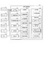
図1は、運行記録装置10のブロック図である。図1に示すように、運行記録装置10は、インターフェース部101と、位置検出部102と、加速度検出部103と、撮影部104と、操作部106と、報知部107と、記憶部110と、処理部120とを含む。  FIG. 1 is a block diagram of theoperation recording apparatus 10. As shown in FIG. 1, theoperation recording apparatus 10 includes aninterface unit 101, aposition detection unit 102, anacceleration detection unit 103, aphotographing unit 104, anoperation unit 106, anotification unit 107, astorage unit 110, And aprocessing unit 120.

インターフェース部101は、運行記録装置10が搭載された車両の各部が出力する信号を伝達する信号線と接続される。インターフェース部101は、複数の信号線を接続できるように構成されてもよい。インターフェース部101は、例えば、ブレーキ(ブレーキユニット)21、ウィンカー(ウィンカーユニット)22、ワイパー(ワイパーユニット)23,エアコン24、ドア25、及びECU(Electronic Control Unit)26等と、それぞれ、信号線により接続される。信号線が接続されるインターフェース部101は、極性を有し、信号線が逆に接続された場合に信号のハイレベルとローレベルが逆転してもよい。運行記録装置10がインターフェース部101を介して受信する信号には、例えば、エンジンの回転数を示す信号、速度を示す信号、走行距離を示す信号(タイヤの回転数を示す信号)、ブレーキ21の状態を示す信号、ウィンカー22の状態を示す信号、ワイパー23の状態を示す信号、エアコン24の状態を示す信号、ドア25の開閉状態を示す信号、及びETC(Electronic Toll Collection System)車載器が出力する信号等が含まれる。インターフェース部101に接続される信号線には、車速を示す車速パルスのように数値情報を表す信号を伝達する信号線と、ON及びOFF等の複数の状態のいずれか1つのような択一的な情報を表す信号を伝達する信号線とが含まれる。  Theinterface unit 101 is connected to a signal line that transmits a signal output from each unit of the vehicle on which theoperation recording device 10 is mounted. Theinterface unit 101 may be configured to connect a plurality of signal lines. Theinterface unit 101 includes, for example, a brake (brake unit) 21, a winker (winker unit) 22, a wiper (wiper unit) 23, anair conditioner 24, adoor 25, an ECU (Electronic Control Unit) 26, etc. Connected. Theinterface unit 101 to which the signal line is connected has a polarity, and the high level and the low level of the signal may be reversed when the signal line is connected in reverse. The signals received by theoperation recording apparatus 10 via theinterface unit 101 include, for example, a signal indicating the engine speed, a signal indicating the speed, a signal indicating the travel distance (a signal indicating the tire speed), and the brake 21 A signal indicating the state, a signal indicating the state of theblinker 22, a signal indicating the state of thewiper 23, a signal indicating the state of theair conditioner 24, a signal indicating the open / closed state of thedoor 25, and an ETC (Electronic Toll Collection System) vehicle-mounted device Signals to be included. The signal line connected to theinterface unit 101 is an alternative such as a signal line for transmitting a signal representing numerical information such as a vehicle speed pulse indicating the vehicle speed, and any one of a plurality of states such as ON and OFF. And a signal line for transmitting a signal representing various information.

位置検出部102は、測位システムの衛生が送信する電波に基づいて、現在位置を検出する。加速度検出部103は、加速度の大きさと方向とを検出する。撮影部104は、運行記録装置10が搭載された車両の外部又は内部を電子的に撮影する。撮影部104は、運行記録装置10の外部に設けられてもよい。  Theposition detection unit 102 detects the current position based on radio waves transmitted by the hygiene of the positioning system. Theacceleration detection unit 103 detects the magnitude and direction of acceleration. The photographingunit 104 electronically photographs the outside or the inside of the vehicle on which theoperation recording device 10 is mounted. Theimaging unit 104 may be provided outside theoperation recording device 10.

操作部106は、運転手等の人による操作を受け付ける。報知部107は、音、光等により、運転手に対して警告等の報知を行う。  Theoperation unit 106 receives an operation by a person such as a driver. Thenotification unit 107 notifies the driver of a warning or the like with sound, light, or the like.

記憶部110は、各種の情報を記憶する。記憶部110は、メモリカード、光ディスク、光磁気ディスク等の非一過的(non-transitory)で可搬の記憶媒体と、記憶媒体の読み書き装置との組み合わせを含んでもよい。  Thestorage unit 110 stores various types of information. Thestorage unit 110 may include a combination of a non-transitory portable storage medium such as a memory card, an optical disk, or a magneto-optical disk, and a storage medium read / write device.

記憶部110は、一時記憶領域111を含む。一時記憶領域111は、撮影部104によって撮影された映像が、静止画又は動画として一時的に記憶される領域である。一時記憶領域111は、映像だけでなく、車速や加速度等の運行情報を一時的に記憶してもよい。  Thestorage unit 110 includes a temporary storage area 111. The temporary storage area 111 is an area in which the video captured by theimaging unit 104 is temporarily stored as a still image or a moving image. The temporary storage area 111 may temporarily store not only images but also operation information such as vehicle speed and acceleration.

記憶部110は、運行情報112と、設定情報113とを記憶する。運行情報112は、運行記録装置10が搭載された車両の運行に関する情報である。設定情報113は、運行記録装置10の動作に関する各種の設定値を含む。設定情報113は、例えば、インターフェース部101に接続された信号線を通じて入力される信号の値と、信号の値が示す状態との対応に関する設定とを含む。  Thestorage unit 110stores operation information 112 and settinginformation 113. Theoperation information 112 is information relating to the operation of the vehicle on which theoperation recording device 10 is mounted. The settinginformation 113 includes various setting values related to the operation of theoperation recording device 10. The settinginformation 113 includes, for example, settings relating to the correspondence between the value of a signal input through a signal line connected to theinterface unit 101 and the state indicated by the signal value.

運行情報112は、状況データ112aと、映像管理データ112bとを含む。運行情報112は、1乃至複数の映像データ112cを含むことができる。状況データ112aは、車両の状況を示す事象に関する情報を含む。映像管理データ112bは、映像データ112cを管理するための情報を含む。映像データ112cは、所定の事象が生じた前後の所定の期間の車外又は車内を撮影した動画である。所定の事象は、例えば、事故の発生を示す事象、事故が発生する可能性が高い事象、又は安全性に関連のある事象である。  Theoperation information 112 includesstatus data 112a andvideo management data 112b. Theoperation information 112 can include one ormore video data 112c. Thesituation data 112a includes information on an event indicating the situation of the vehicle. Thevideo management data 112b includes information for managing thevideo data 112c. Thevideo data 112c is a moving image taken outside or inside the vehicle for a predetermined period before and after a predetermined event occurs. The predetermined event is, for example, an event indicating the occurrence of an accident, an event that is highly likely to occur, or an event related to safety.

図2は、状況データ112aの例を示す図である。図2に示す例において、状況データ112aは、車両ID、データID、種別、記録日付、記録時刻、場所、値等の項目を有する。車両IDの項目には、運行記録装置10が搭載された車両を識別するためのIDが格納される。データIDの項目には、状況データ112aに格納された個々の行を識別するためのIDが格納される。  FIG. 2 is a diagram illustrating an example of thesituation data 112a. In the example illustrated in FIG. 2, thesituation data 112a includes items such as a vehicle ID, a data ID, a type, a recording date, a recording time, a location, and a value. In the item of vehicle ID, an ID for identifying the vehicle on which theoperation recording device 10 is mounted is stored. In the data ID item, an ID for identifying each row stored in thestatus data 112a is stored.

種別の項目には、行に対応する事象の種類を示す値が格納される。例えば、行に対応する事象が右ウィンカーの状態の変化に関するものである場合、種別の項目には「右ウィンカー」が格納される。  In the type item, a value indicating the type of event corresponding to the row is stored. For example, when the event corresponding to the row is related to a change in the state of the right winker, “right winker” is stored in the type item.

記録日付及び記録時刻の項目には、それぞれ、事象が状況データ112aに記録された日付及び時刻が格納される。場所の項目には、事象が発生したときの車両の位置を示す値(例えば、緯度及び経度)が格納される。  In the items of recording date and recording time, the date and time when the event is recorded in thestatus data 112a are stored, respectively. The place item stores values (for example, latitude and longitude) indicating the position of the vehicle when the event occurs.

値の項目には、事象の詳細を示す値が格納される。事象の詳細を示す値は、事象の種類ごとに異なる。例えば、行に対応する事象が右ウィンカーの状態の変化に関するものである場合、事象の詳細を示す値は、右ウィンカーが点灯していること又は点灯を開始したことを示す「ON」、もしくは右ウィンカーが点灯していないこと又は点灯を停止したことを示す「OFF」という択一的な情報である。  In the value item, a value indicating the details of the event is stored. The value indicating the details of the event differs for each event type. For example, when the event corresponding to the row relates to a change in the state of the right winker, the value indicating the details of the event is “ON” indicating that the right winker is lit or started lighting, or right This is alternative information “OFF” indicating that the blinker is not lit or has stopped lighting.

例えば、図2に示す状況データ112aの3つめの行は、「2013/4/3」の「9:38:25」に、「xx.xxxx,zz.zzzz」という場所で、「ブレーキ」が作動したこと(「ON」となったこと)を示している。  For example, the third row of thestatus data 112a shown in FIG. 2 is “2013/4/3” at “9:38:25”, where “xx.xxxx, zz.zzz” is “brake” Indicates that it has been activated (becomes “ON”).

図3は、映像管理データ112bの例を示す図である。図3に示す例において、映像管理データ112bは、車両ID、データID、映像データ名、撮影開始日付、撮影開始時刻、撮影終了日付、撮影終了時刻、重要度等の項目を有する。車両IDの項目には、運行記録装置10が搭載された車両を識別するためのIDが格納される。データIDの項目には、対応する映像データ112cが保存されるきっかけとなった事象に対応する状況データ112aの行を識別するためのIDが格納される。  FIG. 3 is a diagram illustrating an example of thevideo management data 112b. In the example illustrated in FIG. 3, thevideo management data 112b includes items such as a vehicle ID, a data ID, a video data name, a shooting start date, a shooting start time, a shooting end date, a shooting end time, and an importance level. In the item of vehicle ID, an ID for identifying the vehicle on which theoperation recording device 10 is mounted is stored. The data ID item stores an ID for identifying the row of thestatus data 112a corresponding to the event that caused thecorresponding video data 112c to be saved.

映像データ名の項目には、対応する映像データ112cの名前が格納される。撮影開始日付、撮影開始時刻、撮影終了日付及び撮影終了時刻の項目には、対応する映像データ112cの撮影の撮影期間を示す値が格納される。  The name of thecorresponding video data 112c is stored in the video data name item. In the items of shooting start date, shooting start time, shooting end date, and shooting end time, values indicating the shooting period of shooting of thecorresponding video data 112c are stored.

重要度の項目には、対応する映像データ112cの重要度を示す値が格納される。映像データ112cの重要度は、例えば、映像データ112cが保存されるきっかけとなった事象の種類及び事象の詳細を示す値の少なくとも一方に基づいて決定される。映像データ112cの重要度は、例えば、映像データ112cを削除する優先順位を決定するために用いられる。重要度を示す値は、例えば、重要度が高い順に、3から1のいずれかの値をとる。  The importance item stores a value indicating the importance of thecorresponding video data 112c. The importance of thevideo data 112c is determined based on, for example, at least one of the type of event that causes thevideo data 112c to be stored and a value indicating the details of the event. The importance of thevideo data 112c is used, for example, to determine a priority order for deleting thevideo data 112c. The value indicating the importance is, for example, any value from 3 to 1 in descending order of importance.

例えば、図3に示す映像管理データ112bの1つめの行は、対応する映像データ112cが、図2に示す状況データ112aの3つめの行に対応する事象がきっかけとなって保存されたことを示している。  For example, the first row of thevideo management data 112b shown in FIG. 3 indicates that thecorresponding video data 112c is saved due to the event corresponding to the third row of thestatus data 112a shown in FIG. Show.

さらに、この行は、対応する映像データ112cの名前が「20130403−001.jpg」であり、映像データ112cの撮影期間が、「2013/4/3」の「9:37:55」から「2013/4/3」の「9:38:55」までであることを示している。さらに、この行は、対応する映像データ112cの重要度が「3」であることを示している。  Further, in this line, the name of thecorresponding video data 112c is “201303403-001.jpg”, and the shooting period of thevideo data 112c is “2013/4/3” from “9:37:55” to “2013”. / 4/3 "is up to" 9:38:55 ". Further, this row indicates that the importance of thecorresponding video data 112c is “3”.

図4は、設定情報113の例を示す図である。図4に示す設定情報113は、信号の値と、信号の値が示す状態との対応に関する設定を含んでいる。本実施形態では、信号の値のハイレベル及びローレベルの一方が、部位が稼働(作動)していること又は部位が稼働(作動)を開始したことを示す「ON」と対応付けられ、他方が、部位が停止していること又は部位が稼働(作動)を停止したことを示す「OFF」と対応付けられる。設定情報113は、図4に示した設定以外の各種設定を含むことができる。  FIG. 4 is a diagram illustrating an example of the settinginformation 113. The settinginformation 113 illustrated in FIG. 4 includes settings regarding the correspondence between the signal value and the state indicated by the signal value. In the present embodiment, one of the high level and low level of the signal value is associated with “ON” indicating that the part is operating (actuated) or that the part is activated (actuated), and the other Is associated with “OFF” indicating that the part has stopped or that the part has stopped operating. The settinginformation 113 can include various settings other than the settings shown in FIG.

図4に示す例において、設定情報113は、部位、設定時の想定状態、対応、閾値等の項目を有し、部位毎に行が登録される。部位の項目には、状態がON及びOFF等の択一的な値によって示される部位を識別するための値が格納される。部位を識別するための値は、例えば、部位の名前、又は部位のコード等を含む。  In the example illustrated in FIG. 4, the settinginformation 113 includes items such as a part, an assumed state at the time of setting, a correspondence, and a threshold, and a row is registered for each part. In the item of the part, a value for identifying a part indicated by an alternative value such as ON or OFF is stored. The value for identifying the part includes, for example, the part name or the part code.

設定時の想定状態の項目には、信号の値と、信号の値が示す状態との対応を一括して設定する際に想定されている部位の状態を示す値が格納される。例えば、対応を一括して設定する際に部位が稼働(作動)していないことが想定されている場合、その部位に対応する行の設定時の想定状態の項目には、「OFF」が設定される。一方、対応を一括して設定する際に部位が稼働(作動)していることが想定されている場合、その部位に対応する行の設定時の想定状態の項目には、「ON」が設定される。  The assumed state item at the time of setting stores a value indicating the state of the part assumed when setting the correspondence between the signal value and the state indicated by the signal value collectively. For example, if it is assumed that a part is not in operation (actuated) when setting correspondence in a batch, “OFF” is set in the item of the assumed state when setting a row corresponding to that part. Is done. On the other hand, if it is assumed that the part is operating (actuated) when setting the correspondence in a batch, “ON” is set in the item of the assumed state when setting the row corresponding to the part. Is done.

対応の項目には、信号の値と、信号の値に対応する状態を示す値が格納される。部位の状態は、信号の値に基づいて、対応する部位の状態を判定するために用いられる。  The corresponding item stores a signal value and a value indicating a state corresponding to the signal value. The state of the part is used to determine the state of the corresponding part based on the value of the signal.

閾値の項目には、信号の値を判定するための閾値が格納される。信号の値を判定するための閾値は、信号の値がハイレベルであること又はローレベルからハイレベルに変化したことを判定するための第1の閾値と、信号の値がローレベルであること又はハイレベルからローレベルに変化したことを判定するための第2の閾値とを含む。  In the threshold value item, a threshold value for determining a signal value is stored. The threshold value for determining the signal value is the first threshold value for determining that the signal value is high level or has changed from low level to high level, and the signal value is low level. Or a second threshold value for determining that the level has changed from the high level to the low level.

図5Aは、第1の閾値及び第2の閾値の例を示す図である。図5Aに示す例において、信号の電圧が第1の閾値TH1aよりも高い場合に、信号の値がハイレベルであると判定され、信号の電圧が第1の閾値TH1aよりも低い値から高い値へ変化した場合に、信号の値がローレベルからハイレベルに変化したと判定される。また、信号の電圧が第2の閾値TH2aよりも低い場合に、信号の値がローレベルであると判定され、信号の電圧が第2の閾値TH2aよりも高い値から低い値へ変化した場合に、信号の値がハイレベルからローレベルに変化したと判定される。  FIG. 5A is a diagram illustrating an example of the first threshold value and the second threshold value. In the example shown in FIG. 5A, when the signal voltage is higher than the first threshold value TH1a, it is determined that the signal value is at a high level, and the signal voltage is higher than a value lower than the first threshold value TH1a. When the signal changes to, it is determined that the signal value has changed from the low level to the high level. Further, when the signal voltage is lower than the second threshold value TH2a, the signal value is determined to be at a low level, and when the signal voltage changes from a value higher than the second threshold value TH2a to a lower value. , It is determined that the value of the signal has changed from a high level to a low level.

信号の電圧レベルは、車種、年式、部位等によって変動することがある。このため、閾値の項目に設定される第1の閾値及び第2の閾値は、まとめて又は部位毎に変更可能であってもよい。例えば、図5Bに示すように、第1の閾値TH1bを第1の閾値TH1aよりも高く設定することによりハイレベルと判定される範囲を狭くし、第2の閾値TH2bを第2の閾値TH2aよりも低く設定することによりローレベルと判定される範囲を狭くしてもよい。あるいは、図5Cに示すように、第1の閾値TH1cを第1の閾値TH1aよりも低く設定することによりハイレベルと判定される範囲を広くし、第2の閾値TH2cを第2の閾値TH2aよりも高く設定することによりローレベルと判定される範囲を広くしてもよい。閾値の項目に設定される第1の閾値及び第2の閾値は、バッテリの種類に応じて変更可能であってもよい。  The voltage level of the signal may vary depending on the vehicle type, year, location, etc. For this reason, the 1st threshold value and 2nd threshold value which are set to the item of a threshold value may be changeable collectively or for every site | part. For example, as shown in FIG. 5B, by setting the first threshold value TH1b to be higher than the first threshold value TH1a, the range determined to be a high level is narrowed, and the second threshold value TH2b is set to be higher than the second threshold value TH2a. Alternatively, the range that is determined to be low level may be narrowed by setting it low. Alternatively, as shown in FIG. 5C, by setting the first threshold value TH1c to be lower than the first threshold value TH1a, the range that is determined to be a high level is widened, and the second threshold value TH2c is set to be higher than the second threshold value TH2a. Alternatively, the range determined as low level may be widened by setting a higher value. The first threshold and the second threshold set in the threshold item may be changeable according to the type of battery.

図4に示す設定情報113の1つめの行は、「ブレーキ」のユニットは、信号の値と、信号の値が示す状態との対応を一括して設定する際には、「OFF」であること、すなわち、ペダルが踏まれておらずブレーキユニットが作動していない状態であることが想定されていることを示している。さらに、この行は、第1の閾値が8Vであり、第2の閾値が4Vであることを示している。  The first row of the settinginformation 113 shown in FIG. 4 indicates that the “brake” unit is “OFF” when setting the correspondence between the signal value and the state indicated by the signal value collectively. That is, it is assumed that the pedal is not depressed and the brake unit is not operating. In addition, this row indicates that the first threshold is 8V and the second threshold is 4V.

処理部120は、運行記録装置10の機能を実現するための各種の処理を実行する。処理部120は、情報取得部121と、状況記録部122と、映像記録部123と、情報送信部124と、情報管理部125と、設定管理部126を有する。  Theprocessing unit 120 executes various processes for realizing the functions of theoperation recording apparatus 10. Theprocessing unit 120 includes aninformation acquisition unit 121, astatus recording unit 122, avideo recording unit 123, aninformation transmission unit 124, aninformation management unit 125, and asetting management unit 126.

情報取得部121は、車両の運行に関する情報を取得する。情報取得部121が取得する情報には、インターフェース部101を介して受信する各種の信号が示す情報、運行記録装置10に内蔵又は接続された各種検出部が検出した情報、及び撮影部104の撮影によって得られた静止画又は動画が含まれる。  Theinformation acquisition unit 121 acquires information related to vehicle operation. The information acquired by theinformation acquisition unit 121 includes information indicated by various signals received via theinterface unit 101, information detected by various detection units built in or connected to theoperation recording apparatus 10, and imaging by theimaging unit 104. The still image or moving image obtained by is included.

状況記録部122は、情報取得部121が取得した情報に基づいて、車両の状況を示す事象に関する情報を状況データ112aに記録する。状況記録部122は、例えば、情報取得部121が取得した情報を一時記憶部111に一時的に記憶させ、所定の条件を満たした場合に、一時的に記憶している情報を状況データ112aに記録する。  Based on the information acquired by theinformation acquisition unit 121, thestatus recording unit 122 records information on an event indicating the vehicle status in thestatus data 112a. For example, thestatus recording unit 122 temporarily stores the information acquired by theinformation acquisition unit 121 in the temporary storage unit 111, and when the predetermined condition is satisfied, the temporarily stored information is stored in thestatus data 112a. Record.

映像記録部123は、情報取得部121が取得した静止画又は動画を一時的に一時記憶領域111に記憶させ、所定の事象が発生した場合に、一時記憶領域111に記憶されているデータに基づいて、その事象が発生した前後の所定の期間の動画を生成する。映像記録部123は、生成した動画を映像データ112cとして保存し、動画を管理するための情報を映像管理データ112bに追加する。  Thevideo recording unit 123 temporarily stores the still image or moving image acquired by theinformation acquisition unit 121 in the temporary storage area 111, and based on the data stored in the temporary storage area 111 when a predetermined event occurs. Thus, a moving image of a predetermined period before and after the occurrence of the event is generated. Thevideo recording unit 123 stores the generated moving image as thevideo data 112c, and adds information for managing the moving image to thevideo management data 112b.

所定の事象が発生したか否かを判定するための基準は、設定情報113に設定される。この基準に基づいて、映像記録部123は、例えば、速度が閾値を超えた場合、閾値よりも大きい加速度が検出された場合、ブレーキペダルが踏まれた場合、及びウィンカーが動作した場合等に映像データ112cを保存する。設定情報113に設定される基準は、任意に追加、削除、及び変更することができる。設定情報113に設定される基準は、運転手ごとに異ならせることができる。例えば、急発進及び急停止が多い運転手の場合、加速度に関する閾値を通常よりも大きく設定することにより、大量の映像データ112cが保存される事態が生じる可能性を低減できる。  A reference for determining whether or not a predetermined event has occurred is set in the settinginformation 113. Based on this criterion, thevideo recording unit 123, for example, displays video when the speed exceeds a threshold, when acceleration greater than the threshold is detected, when the brake pedal is depressed, or when the blinker is operated, etc. Save thedata 112c. The reference set in the settinginformation 113 can be arbitrarily added, deleted, and changed. The reference set in the settinginformation 113 can be different for each driver. For example, in the case of a driver who frequently starts and stops, the possibility that a large amount ofvideo data 112c may be saved can be reduced by setting a threshold value related to acceleration larger than usual.

状況記録部122及び映像記録部123は、情報取得部121が取得した情報が示す状態を設定情報113に基づいて判定する。例えば、ある部位に関して、設定情報113において、信号の値のローレベルが、部位の「OFF」の状態と対応付けられ、信号の値のハイレベルが、部位の「ON」の状態と対応付けられているものとする。この場合、状況記録部122及び映像記録部123は、その部位に対応する信号線から情報取得部121が取得した信号の値がローレベルであれば、部位が「OFF」の状態にある又は「OFF」の状態に変化したと判定し、その部位に対応する信号線から情報取得部121が取得した信号の値がハイレベルであれば、部位が「ON」の状態にある又は「ON」の状態に変化したと判定する。  Thestatus recording unit 122 and thevideo recording unit 123 determine the state indicated by the information acquired by theinformation acquisition unit 121 based on the settinginformation 113. For example, regarding a certain part, in the settinginformation 113, the low level of the signal value is associated with the “OFF” state of the part, and the high level of the signal value is associated with the “ON” state of the part. It shall be. In this case, if the value of the signal acquired by theinformation acquisition unit 121 from the signal line corresponding to the part is low level, thestate recording part 122 and thevideo recording part 123 are in the “OFF” state or “ If it is determined that the state has changed to "OFF" and the value of the signal acquired by theinformation acquisition unit 121 from the signal line corresponding to the part is high, the part is in the "ON" state or "ON" It is determined that the state has changed.

情報送信部124は、運行情報112を他の装置へ送信するための処理を行う。情報管理部125は、不要な情報又は重要度の低い情報の削除等の、情報の管理を行う。  Theinformation transmission unit 124 performs processing for transmitting theoperation information 112 to another device. Theinformation management unit 125 manages information such as deleting unnecessary information or less important information.

設定管理部126は、運行記録装置10の各種動作に関する設定を管理する。例えば、設定管理部126は、操作部106に対する所定の操作が検出されると、そのときにインターフェース部101を介して入力される信号の値に基づいて、信号の値と、信号の値が示す状態との対応を一括して設定する設定処理を実行する。設定処理においては、設定情報113の対応の項目の設定値が一括して更新される。  Thesetting management unit 126 manages settings related to various operations of theoperation recording apparatus 10. For example, when a predetermined operation on theoperation unit 106 is detected, thesetting management unit 126 indicates the signal value and the signal value based on the signal value input via theinterface unit 101 at that time. Executes a setting process that collectively sets the correspondence with the state. In the setting process, the setting values of the corresponding items in the settinginformation 113 are updated in a batch.

さらに、設定管理部126は、操作部106に対して行われる操作に応じて、設定情報113の対応の項目の設定値を個別に更新する。このように、設定値を個別に更新することにより、極性が反転するようにインターフェース部101への信号線の接続をやり直すといった物理的な変更を伴う変更作業を行わなくても、信号の値と、信号の値が示す状態との対応を容易に変更することができる。  Furthermore, thesetting management unit 126 individually updates the setting values of the corresponding items in the settinginformation 113 in accordance with operations performed on theoperation unit 106. Thus, by updating the set value individually, the signal value and the signal value can be obtained without performing a change operation involving physical change such as reconnecting the signal line to theinterface unit 101 so that the polarity is reversed. The correspondence with the state indicated by the signal value can be easily changed.

図6及び図7を参照しながら、運行記録装置10の動作についてより詳細に説明する。図6は、信号の値と、信号の値が示す状態との対応を一括して設定する設定処理時の運行記録装置10の動作の例を示すフローチャートである。図6に示す動作は、操作部106に対して所定の操作が行われた場合に、信号の値に基づいて状態が判定される部位毎に実行される。それぞれの部位に関する動作は、1つずつ実行されてもよいし、並行して実行されてもよい。図6に示す動作の前に、車両の各部位は、信号の値と、信号の値が示す状態との対応を一括して設定する際に想定されている状態にされる。例えば、設定情報113が図4に示した通りの場合、図6に示す動作の前に、ブレーキ及びアクセルは、ペダルが踏まれていない状態にされ、ウィンカー、ワイパー、及びエアコンは作動していない状態(OFF状態)にされる。イグニッションスイッチをONにしてから、所定の操作をした場合(例えば、操作部106を操作した場合)、設定管理部126は、車両の各部位からインターフェース部101を介して入力される信号の値(電圧値)と各部位の状態(ここではOFF状態)との対応を一括して設定する設定処理を実行する。ここでの例は、信号の値は、図5Aから図5Cに示す第1の閾値(TH1aからTH1c)及び第2の閾値(TH2aからTH2c)から、ハイレベルであるかローレベルであるかを判定され、設定管理部126で、そのレベルと各部位の状態との対応が一括で設定されている。例えば、設定管理部126は、第1レベルの電位を検出した場合、第1レベルの電気信号を第1の状態と設定情報113に設定し、第1レベルの電気信号と異なる第2レベルの電気信号を第2の状態と設定情報113に設定する。より具体的には、設定管理部126は、例えば、ある部位に対応する信号について、第1の閾値よりも高い電位の電気信号を検出した場合、第1の閾値よりも高い電位の電気信号をONの状態と設定情報113に設定し、第2の閾値よりも低い電位の電気信号をOFFの状態と設定情報113に設定する。あるいは、設定管理部126は、例えば、ある部位に対応する信号について、第2の閾値よりも低い電位の電気信号を検出した場合、第2の閾値よりも低い電位の電気信号をONの状態と設定情報113に設定し、第1の閾値よりも高い電位の電気信号をOFFの状態と設定情報113に設定する。ONの状態とOFFの状態は、設定する際に想定されている状態に応じて、入れ替わることがある。  The operation of theoperation recording device 10 will be described in more detail with reference to FIGS. FIG. 6 is a flowchart showing an example of the operation of theoperation recording apparatus 10 during the setting process for collectively setting the correspondence between the signal value and the state indicated by the signal value. The operation illustrated in FIG. 6 is executed for each part whose state is determined based on the value of the signal when a predetermined operation is performed on theoperation unit 106. The operations relating to the respective parts may be executed one by one or in parallel. Before the operation shown in FIG. 6, each part of the vehicle is brought into a state assumed when the correspondence between the signal value and the state indicated by the signal value is collectively set. For example, when the settinginformation 113 is as shown in FIG. 4, before the operation shown in FIG. 6, the brake and the accelerator are not depressed, and the winker, the wiper, and the air conditioner are not operated. The state (OFF state) is set. When a predetermined operation is performed after the ignition switch is turned on (for example, when theoperation unit 106 is operated), thesetting management unit 126 receives a value of a signal input from each part of the vehicle via the interface unit 101 ( A setting process for collectively setting the correspondence between the voltage value) and the state of each part (here, the OFF state) is executed. In this example, whether the signal value is high or low from the first threshold (TH1a to TH1c) and the second threshold (TH2a to TH2c) shown in FIGS. 5A to 5C. Thesetting management unit 126 collectively determines the correspondence between the level and the state of each part. For example, when thesetting management unit 126 detects the first level electric potential, thesetting management unit 126 sets the first level electric signal in the first state and the settinginformation 113, and the second level electric signal different from the first level electric signal. The signal is set in the second state and settinginformation 113. More specifically, for example, when thesetting management unit 126 detects an electrical signal having a potential higher than the first threshold for a signal corresponding to a certain part, thesetting management unit 126 outputs the electrical signal having a potential higher than the first threshold. An ON state and settinginformation 113 are set, and an electric signal having a potential lower than the second threshold is set in the OFF state and settinginformation 113. Alternatively, for example, when thesetting management unit 126 detects an electrical signal having a potential lower than the second threshold for a signal corresponding to a certain part, thesetting management unit 126 sets the electrical signal having a potential lower than the second threshold to an ON state. The settinginformation 113 is set, and an electrical signal having a potential higher than the first threshold is set in the OFF state and the settinginformation 113. The ON state and the OFF state may be switched depending on the state assumed when setting.

所定の操作(初期設定モードON)が受け付けられると(ステップS101)、処理部120の設定管理部126は、部位に対応する設定情報113の行の設定時の想定状態の項目の値を取得する(ステップS102)。そして、設定管理部126は、部位に対応する信号の値を判定する(ステップS103)。そして、設定管理部126は、以下の様にして、設定時の想定状態と、信号の値との対応を取る。  When a predetermined operation (initial setting mode ON) is accepted (step S101), thesetting management unit 126 of theprocessing unit 120 acquires the value of the item in the assumed state at the time of setting the row of the settinginformation 113 corresponding to the part. (Step S102). And thesetting management part 126 determines the value of the signal corresponding to a site | part (step S103). Then, thesetting management unit 126 takes the correspondence between the assumed state at the time of setting and the signal value as follows.

信号の値がハイレベルの場合(ステップS104,Yes)、設定管理部126は、ステップS102で取得した値(設定時の想定状態の項目の値)が「ON」であるかを判定する(ステップS105)。ステップS102で取得した値が「ON」である場合(ステップS105,Yes)、現在の信号の値であるハイレベルが「ON」の状態に対応し、信号の値のローレベルが「OFF」の状態に対応するように、部位に対応する設定情報113の行の対応の項目の値を設定する(ステップS106)。ステップS102で取得した値が「ON」でない場合(ステップS105,No)、現在の信号の値であるハイレベルが「OFF」の状態に対応し、信号の値のローレベルが「ON」の状態に対応するように、部位に対応する設定情報113の行の対応の項目の値を設定する(ステップS107)。  When the value of the signal is high level (step S104, Yes), thesetting management unit 126 determines whether the value acquired in step S102 (the value of the item in the assumed state at the time of setting) is “ON” (step S102). S105). When the value acquired in step S102 is “ON” (step S105, Yes), the high level that is the current signal value corresponds to the state of “ON”, and the low level of the signal value is “OFF”. The value of the corresponding item in the row of the settinginformation 113 corresponding to the part is set so as to correspond to the state (step S106). When the value acquired in step S102 is not “ON” (No in step S105), the current signal value high level corresponds to the “OFF” state, and the signal value low level is “ON”. The value of the corresponding item in the row of the settinginformation 113 corresponding to the part is set so as to correspond to (Step S107).

一方、信号の値がローレベルの場合(ステップS104,No、かつ、ステップS108,Yes)、設定管理部126は、ステップS102で取得した値(設定時の想定状態の項目の値)が「ON」であるかを判定する(ステップS109)。ステップS102で取得した値が「ON」である場合(ステップS109,Yes)、現在の信号の値であるローレベルが「ON」の状態に対応し、信号の値のハイレベルが「OFF」の状態に対応するように、部位に対応する設定情報113の行の対応の項目の値を設定する(ステップS110)。ステップS102で取得した値が「ON」でない場合(ステップS109,No)、現在の信号の値であるローレベルが「OFF」の状態に対応し、信号の値のハイレベルが「ON」の状態に対応するように、部位に対応する設定情報113の行の対応の項目の値を設定する(ステップS111)。  On the other hand, when the value of the signal is low level (step S104, No, and step S108, Yes), thesetting management unit 126 indicates that the value acquired in step S102 (the value of the item in the assumed state at the time of setting) is “ON”. Is determined (step S109). When the value acquired in step S102 is “ON” (step S109, Yes), the low level that is the current signal value corresponds to the state of “ON”, and the high level of the signal value is “OFF”. In order to correspond to the state, the value of the corresponding item in the row of the settinginformation 113 corresponding to the part is set (step S110). When the value acquired in step S102 is not “ON” (No in step S109), the low level that is the current signal value corresponds to the state of “OFF”, and the high level of the signal value is “ON”. The value of the corresponding item in the row of the settinginformation 113 corresponding to the part is set so as to correspond to (Step S111).

図7は、部位の状態を記録する記録処理時の運行記録装置10の動作の例を示すフローチャートである。図7に示す動作は、必要に応じて、判定対象の部位毎に実行される。  FIG. 7 is a flowchart showing an example of the operation of theoperation recording apparatus 10 during the recording process for recording the state of the part. The operation shown in FIG. 7 is executed for each part to be determined as necessary.

状況記録部122は、部位に対応する信号の値を判定し(ステップS201)、部位に対応する設定情報113の行の対応の項目の設定値を取得する(ステップS202)。そして、状況記録部122は、取得した設定値が示す対応に基づいて、ステップS201で判定した信号の値に対応する状態を判定する(ステップS203)。  Thestatus recording unit 122 determines the value of the signal corresponding to the part (step S201), and acquires the setting value of the corresponding item in the row of the settinginformation 113 corresponding to the part (step S202). Then, thestatus recording unit 122 determines a state corresponding to the value of the signal determined in step S201 based on the correspondence indicated by the acquired setting value (step S203).

判定した状態が「ON」の状態の場合(ステップS204,Yes)、状況記録部122は、状況データ112aに、部位の状態として「ON」を記録する(ステップS205)。一方、判定した状態が「ON」でない状態の場合(ステップS204,No)、状況記録部122は、状況データ112aに、部位の状態として「OFF」を記録する(ステップS206)。  When the determined state is “ON” (step S204, Yes), thesituation recording unit 122 records “ON” as the state of the part in thesituation data 112a (step S205). On the other hand, when the determined state is not “ON” (No at Step S204), thesituation recording unit 122 records “OFF” as the state of the part in thesituation data 112a (Step S206).

上述してきたように、運行記録装置10は、現在の信号の値が対応する部位の予め想定されている状態を表しているという前提に基づいて、信号の値と、信号の値が示す状態との対応を設定する。このため、各部位の状態を予め想定されている状態にして設定処理を実行することにより、対応を設定すべき部位が複数ある場合でも、それらの対応を一括して、容易かつ正しく設定することができる。予め想定されている状態は、例えば、新車にキーをさしてACCまで回したときの状態のように、容易に再現することができる状態であることが好ましい。予め想定されている状態は、例えば、状態が判定される全ての部位がOFFの状態であってもよい。  As described above, theoperation recording device 10 is based on the premise that the current signal value represents a presumed state of the corresponding part, and the signal value and the signal value state. Set the correspondence of. For this reason, by executing the setting process with the state of each part assumed in advance, even when there are a plurality of parts for which correspondence should be set, the correspondence can be easily and correctly set in a lump. Can do. It is preferable that the state assumed in advance is a state that can be easily reproduced, for example, a state when a key is put on a new vehicle and the vehicle is turned to ACC. The state assumed in advance may be, for example, a state in which all the parts whose states are determined are OFF.

本願の実施形態及びその変形例は、発明の要旨を逸脱しない範囲で、適宜変更することができる。さらに、本願の実施形態及びその変形例は、適宜組み合わせることができる。  The embodiments of the present application and modifications thereof may be changed as appropriate without departing from the spirit of the invention. Furthermore, the embodiment of the present application and its modifications can be combined as appropriate.

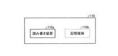
例えば、記憶部110が、メモリカード、光ディスク、光磁気ディスク等の非一過的で可搬の記憶媒体と、記憶媒体の読み書き装置との組み合わせを含んでいる場合、運行記録装置10は、記憶媒体が運行記録装置10に挿入されているか否かに応じて、動作を変更してもよい。図8は、可搬の記憶媒体110bを読み書きする読み書き装置110aを有する記憶部110の例を示す図である。図8に示す例では、運行記録装置10は、記憶媒体110bを着脱可能に構成され、記憶媒体110bが運行記録装置10に挿入されているときに、読み書き装置110aは、記憶媒体110bに対して情報を読み書きする。記憶媒体110bは、例えば、運行情報112を記憶し、記憶している運行情報112を他の装置へ移すために用いられる。  For example, when thestorage unit 110 includes a combination of a non-transitory portable storage medium such as a memory card, an optical disk, or a magneto-optical disk, and a read / write device for the storage medium, theoperation recording apparatus 10 stores The operation may be changed depending on whether a medium is inserted in theoperation recording apparatus 10 or not. FIG. 8 is a diagram illustrating an example of thestorage unit 110 including the read /write device 110a that reads and writes theportable storage medium 110b. In the example illustrated in FIG. 8, theoperation recording device 10 is configured to be detachable from thestorage medium 110b, and when thestorage medium 110b is inserted into theoperation recording device 10, the read /write device 110a is connected to thestorage medium 110b. Read and write information. Thestorage medium 110b is used, for example, for storingoperation information 112 and transferring the storedoperation information 112 to another device.

図9は、記憶媒体が挿入されているか否かに応じて、運行記録装置10の動作を変更する例を示すフローチャートである。運行記録装置10の処理部120は、操作部106に対する所定の操作を検出すると(ステップS301)、記憶媒体110bの状態を判定する(ステップS302)。  FIG. 9 is a flowchart illustrating an example of changing the operation of theoperation recording apparatus 10 depending on whether or not a storage medium is inserted. When detecting a predetermined operation on the operation unit 106 (step S301), theprocessing unit 120 of theoperation recording apparatus 10 determines the state of thestorage medium 110b (step S302).

記憶媒体110bが運行記録装置10に挿入されている場合(ステップS303,Yes)、処理部120は、操作に応じた通常動作を実行する(ステップS304)。記憶媒体110bが運行記録装置10に挿入されていない場合(ステップS303,No)、処理部120は、図6に示した設定処理を実行する(ステップS305)。  When thestorage medium 110b is inserted in the operation recording apparatus 10 (step S303, Yes), theprocessing unit 120 performs a normal operation according to the operation (step S304). When thestorage medium 110b is not inserted in the operation recording apparatus 10 (No at Step S303), theprocessing unit 120 executes the setting process illustrated in FIG. 6 (Step S305).

このように、記憶媒体110bが挿入されているか否かに応じて、操作に対応する動作を切り替えることにより、1つの操作に複数の動作を対応付けることができる。これにより、操作部106が備えるボタン等の操作部品を減らしつつ、多様な操作を受け付けることが可能になる。さらに、記憶媒体110bが挿入されていないときの動作として、図6に示した設定処理を実行することにより、運行記録装置10が通常稼働しているときに誤操作によって設定処理が実行される可能性を低くすることができる。例えば、運行記録装置10に記憶媒体110bが挿入され、走行中の車両の状況を記憶媒体110bに記録しているときに誤操作によって設定処理が実行されると、各部位が想定外の状態で設定処理が実行されるため、対応が誤って更新され、車両の状況が正しく記録されないおそれがある。  Thus, a plurality of operations can be associated with one operation by switching the operation corresponding to the operation depending on whether or not thestorage medium 110b is inserted. Thereby, it becomes possible to accept various operations while reducing operation parts such as buttons provided in theoperation unit 106. Furthermore, by performing the setting process shown in FIG. 6 as an operation when thestorage medium 110b is not inserted, the setting process may be executed by an erroneous operation when theoperation recording apparatus 10 is operating normally. Can be lowered. For example, when thestorage medium 110b is inserted in theoperation recording device 10 and the setting process is executed by an erroneous operation when the state of the running vehicle is recorded in thestorage medium 110b, each part is set in an unexpected state. Since the process is executed, the correspondence may be erroneously updated, and the vehicle status may not be recorded correctly.

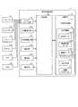
運行記録装置10の処理部120の機能は、ソフトウェアを用いて実現されてもよい。図10は、運行記録装置10の変形例のブロック図である。図10に示す運行記録装置11は、処理部120の代わりに制御部130を備える点と、記憶部110が制御プログラム114をさらに備える点とにおいて、図1に示した運行記録装置10と異なる。  The function of theprocessing unit 120 of theoperation recording apparatus 10 may be realized using software. FIG. 10 is a block diagram of a modified example of theoperation recording apparatus 10. Theoperation recording apparatus 11 illustrated in FIG. 10 is different from theoperation recording apparatus 10 illustrated in FIG. 1 in that theoperation recording apparatus 11 includes acontrol unit 130 instead of theprocessing unit 120, and thestorage unit 110 further includes acontrol program 114.

制御部130は、運行記録装置11の動作を統合的に制御する。制御部130は、例えば、CPU(Central Processing Unit)等の演算処理装置と、演算処理装置の演算値等を格納するメモリとを有する。制御部130は、記憶部110が記憶するプログラムをメモリに展開し、プログラムに含まれる命令に基づく演算を行いながらプログラムを実行することによって、各種の機能を実現する。例えば、制御部130は、制御プログラム114を実行することによって、処理部120と同様の機能を実現する。  Thecontrol unit 130 controls the operation of theoperation recording device 11 in an integrated manner. Thecontrol unit 130 includes, for example, an arithmetic processing device such as a CPU (Central Processing Unit) and a memory that stores arithmetic values of the arithmetic processing device. Thecontrol unit 130 implements various functions by developing a program stored in thestorage unit 110 in a memory and executing the program while performing an operation based on an instruction included in the program. For example, thecontrol unit 130 implements the same function as theprocessing unit 120 by executing thecontrol program 114.

プログラム及びデータは、必要に応じて、集約又は分散されてもよい。  Programs and data may be aggregated or distributed as needed.

上記の実施形態及び変形例では、運行記録装置10及び11が動画を記録する機能を有する例について説明したが、運行記録装置10及び11は、動画を記録する機能をもたなくてもよい。  In the above embodiment and the modification, the example in which theoperation recording devices 10 and 11 have a function of recording a moving image has been described. However, theoperation recording devices 10 and 11 may not have a function of recording a moving image.

10、11 運行記録装置
101 インターフェース部
102 位置検出部
103 加速度検出部
104 撮影部
106 操作部
107 報知部
110 記憶部
111 一時記憶領域
112 運行情報
113 設定情報
114 制御プログラム
120 処理部
121 情報取得部
122 状況記録部
123 映像記録部
124 情報送信部
125 情報管理部
126 設定管理部
130 制御部
10, 11Operation recording device 101Interface unit 102Position detection unit 103Acceleration detection unit 104Imaging unit 106Operation unit 107Notification unit 110 Storage unit 111Temporary storage area 112Operation information 113Setting information 114Control program 120Processing unit 121Information acquisition unit 122Status recording unit 123Video recording unit 124Information transmission unit 125Information management unit 126Setting management unit 130 Control unit

Claims (6)

Translated fromJapanese
車両に搭載される運行記録装置において、
前記車両の部位の状態を示す信号を伝達する信号線と接続されるインターフェース部と、
前記部位が所定の状態にあるときの前記信号の値を取得して、前記信号の値と前記部位の状態との対応に関する設定情報を設定する設定管理部と、
前記設定管理部が設定した前記設定情報に基づいて、前記信号の値が示す前記部位の状態を判定し、前記部位の状態を記録する状況記録部と
を備える運行記録装置。
In the operation recording device mounted on the vehicle,
An interface unit connected to a signal line for transmitting a signal indicating a state of a part of the vehicle;
A setting management unit that acquires a value of the signal when the part is in a predetermined state, and sets setting information regarding a correspondence between the value of the signal and the state of the part;
An operation recording apparatus comprising: a status recording unit that determines a state of the part indicated by the value of the signal based on the setting information set by the setting management unit and records the state of the part.
前記設定管理部は、設定が必要な複数の部位に関して、それぞれ前記信号の取得を行い、それぞれの部位の状態を示す信号の値と該部位の状態との対応に関する前記設定情報を一括して設定する請求項1に記載の運行記録装置。  The setting management unit acquires the signal for each of a plurality of parts that need to be set, and collectively sets the setting information regarding the correspondence between the value of the signal indicating the state of each part and the state of the part. The operation recording device according to claim 1. 操作を受け付ける操作部をさらに備え、
前記設定管理部は、前記操作部が受け付けた操作に応じて、前記設定情報を更新する請求項1又は2に記載の運行記録装置。
It further includes an operation unit for receiving an operation,
The operation recording apparatus according to claim 1, wherein the setting management unit updates the setting information in accordance with an operation received by the operation unit.
可搬の記憶媒体に前記部位の状態を書き込む読み書き装置をさらに備え、
前記設定管理部は、前記記憶媒体が、前記運行記録装置に挿入されていないときに前記操作部が所定の操作を受け付けた場合には、前記部位が所定の状態にあるときの前記信号の値に基づいて前記設定情報を設定する設定処理を実行し、前記記憶媒体が、前記運行記録装置に挿入されているときに前記操作部が前記所定の操作を受け付けた場合には、前記設定処理を実行しない請求項3に記載の運行記録装置。
A read / write device for writing the state of the part on a portable storage medium;
The setting management unit, when the operation unit receives a predetermined operation when the storage medium is not inserted in the operation recording device, the value of the signal when the part is in a predetermined state If the operation unit accepts the predetermined operation when the storage medium is inserted in the operation recording device, the setting processis performed. The operation recording device according to claim 3 which isnot executed .
前記部位の状態は、複数の状態のいずれか1つを示す択一的な情報である請求項1から4のいずれか1項に記載の運行記録装置。  The operation recording apparatus according to any one of claims 1 to 4, wherein the state of the part is alternative information indicating any one of a plurality of states. 前記設定管理部は、第1レベルの電位を検出した場合、第1レベルの電気信号を第1の状態と前記設定情報に設定し、前記第1レベルの電気信号と異なる第2レベルの電気信号を第2の状態と前記設定情報に設定する請求項1から5のいずれか1項に記載の運行記録装置。  When the setting management unit detects a first level electric potential, the setting management unit sets an electric signal of the first level in the first state and the setting information, and an electric signal of a second level different from the electric signal of the first level. The operation recording device according to any one of claims 1 to 5, wherein a second state and the setting information are set.
JP2013167901A2013-08-122013-08-12 Operation recording deviceExpired - Fee RelatedJP6152012B2 (en)

Priority Applications (1)

Application NumberPriority DateFiling DateTitle
JP2013167901AJP6152012B2 (en)2013-08-122013-08-12 Operation recording device

Applications Claiming Priority (1)

Application NumberPriority DateFiling DateTitle
JP2013167901AJP6152012B2 (en)2013-08-122013-08-12 Operation recording device

Publications (2)

Publication NumberPublication Date
JP2015036869A JP2015036869A (en)2015-02-23
JP6152012B2true JP6152012B2 (en)2017-06-21

Family

ID=52687341

Family Applications (1)

Application NumberTitlePriority DateFiling Date
JP2013167901AExpired - Fee RelatedJP6152012B2 (en)2013-08-122013-08-12 Operation recording device

Country Status (1)

CountryLink
JP (1)JP6152012B2 (en)

Families Citing this family (1)

* Cited by examiner, † Cited by third party
Publication numberPriority datePublication dateAssigneeTitle
WO2019111336A1 (en)*2017-12-052019-06-13みなと観光バス株式会社Digital tachograph, and operation management system

Family Cites Families (2)

* Cited by examiner, † Cited by third party
Publication numberPriority datePublication dateAssigneeTitle
JP3189910B2 (en)*1992-06-302001-07-16矢崎総業株式会社 Operation information collection device for work vehicles
JP6046343B2 (en)*2011-12-282016-12-14矢崎エナジーシステム株式会社 Drive recorder

Also Published As

Publication numberPublication date
JP2015036869A (en)2015-02-23

Similar Documents

PublicationPublication DateTitle
US10580456B2 (en)Driving information recording apparatus
JP6476423B2 (en) Recording apparatus and program
JP6216160B2 (en) Operation management system and operation recording device
JP2012003607A (en)Drive recorder for vehicle and recorded information management method
JP2013182573A (en)Drive recorder, data recording method, and program
WO2019146488A1 (en)Driving state monitoring device, driving state monitoring method, and driving state monitoring system
KR101557283B1 (en)Apparatus and method for detecting the faking of meter in vehicle
JP6063189B2 (en) Drive recorder
JP2019164403A (en)Recording control device, recording control method, and recording control program
JP7070278B2 (en) Drive recorder and status information management system
JP5312078B2 (en) Drive recorder and setting reflection method in drive recorder
JP2007011907A (en)Driving recorder
JP7370446B2 (en) In-vehicle video recording device and its control method
CN112639893B (en)Vehicle recording control device, vehicle imaging device, vehicle recording control method, and program
JP2019139291A (en)Information recording device and information recording method
JP6152012B2 (en) Operation recording device
JP6175288B2 (en) Drive recorder
KR102315541B1 (en)A Blackbox Having ouptting event image in case of starting
CN115135537A (en) In-vehicle devices and servers
WO2020262130A1 (en)Driving recorder, data recording method, and program
JP2000146765A (en) Vehicle electronic control unit
JP6568406B2 (en) Drive recorder
JP2019106190A (en)Recording apparatus and program
JP2020008985A (en) Video data management system
JP6959587B2 (en) Vehicle record control device and vehicle record control method

Legal Events

DateCodeTitleDescription
A621Written request for application examination

Free format text:JAPANESE INTERMEDIATE CODE: A621

Effective date:20160511

A977Report on retrieval

Free format text:JAPANESE INTERMEDIATE CODE: A971007

Effective date:20170209

A131Notification of reasons for refusal

Free format text:JAPANESE INTERMEDIATE CODE: A131

Effective date:20170221

A521Written amendment

Free format text:JAPANESE INTERMEDIATE CODE: A523

Effective date:20170308

TRDDDecision of grant or rejection written
A01Written decision to grant a patent or to grant a registration (utility model)

Free format text:JAPANESE INTERMEDIATE CODE: A01

Effective date:20170509

A61First payment of annual fees (during grant procedure)

Free format text:JAPANESE INTERMEDIATE CODE: A61

Effective date:20170526

R150Certificate of patent or registration of utility model

Ref document number:6152012

Country of ref document:JP

Free format text:JAPANESE INTERMEDIATE CODE: R150

LAPSCancellation because of no payment of annual fees

[8]ページ先頭

©2009-2025 Movatter.jp