JP6151617B2 - Bone treatment system - Google Patents
Bone treatment systemDownload PDFInfo
- Publication number
- JP6151617B2 JP6151617B2JP2013202748AJP2013202748AJP6151617B2JP 6151617 B2JP6151617 B2JP 6151617B2JP 2013202748 AJP2013202748 AJP 2013202748AJP 2013202748 AJP2013202748 AJP 2013202748AJP 6151617 B2JP6151617 B2JP 6151617B2
- Authority
- JP
- Japan
- Prior art keywords
- bone
- balloon
- filling material
- treatment system
- shaft
- Prior art date
- Legal status (The legal status is an assumption and is not a legal conclusion. Google has not performed a legal analysis and makes no representation as to the accuracy of the status listed.)
- Active
Links
Images


Classifications
- A—HUMAN NECESSITIES
- A61—MEDICAL OR VETERINARY SCIENCE; HYGIENE
- A61B—DIAGNOSIS; SURGERY; IDENTIFICATION
- A61B17/00—Surgical instruments, devices or methods
- A61B17/56—Surgical instruments or methods for treatment of bones or joints; Devices specially adapted therefor
- A61B17/58—Surgical instruments or methods for treatment of bones or joints; Devices specially adapted therefor for osteosynthesis, e.g. bone plates, screws or setting implements
- A61B17/68—Internal fixation devices, including fasteners and spinal fixators, even if a part thereof projects from the skin
- A61B17/70—Spinal positioners or stabilisers, e.g. stabilisers comprising fluid filler in an implant
- A61B17/7097—Stabilisers comprising fluid filler in an implant, e.g. balloon; devices for inserting or filling such implants
- A—HUMAN NECESSITIES
- A61—MEDICAL OR VETERINARY SCIENCE; HYGIENE
- A61B—DIAGNOSIS; SURGERY; IDENTIFICATION
- A61B17/00—Surgical instruments, devices or methods
- A61B17/56—Surgical instruments or methods for treatment of bones or joints; Devices specially adapted therefor
- A61B17/58—Surgical instruments or methods for treatment of bones or joints; Devices specially adapted therefor for osteosynthesis, e.g. bone plates, screws or setting implements
- A61B17/88—Osteosynthesis instruments; Methods or means for implanting or extracting internal or external fixation devices
- A61B17/8802—Equipment for handling bone cement or other fluid fillers
- A61B17/8805—Equipment for handling bone cement or other fluid fillers for introducing fluid filler into bone or extracting it
- A—HUMAN NECESSITIES
- A61—MEDICAL OR VETERINARY SCIENCE; HYGIENE
- A61B—DIAGNOSIS; SURGERY; IDENTIFICATION
- A61B17/00—Surgical instruments, devices or methods
- A61B17/56—Surgical instruments or methods for treatment of bones or joints; Devices specially adapted therefor
- A61B17/58—Surgical instruments or methods for treatment of bones or joints; Devices specially adapted therefor for osteosynthesis, e.g. bone plates, screws or setting implements
- A61B17/68—Internal fixation devices, including fasteners and spinal fixators, even if a part thereof projects from the skin
- A61B17/72—Intramedullary devices, e.g. pins or nails
- A61B17/7233—Intramedullary devices, e.g. pins or nails with special means of locking the nail to the bone
- A61B17/7258—Intramedullary devices, e.g. pins or nails with special means of locking the nail to the bone with laterally expanding parts, e.g. for gripping the bone
- A61B17/7275—Intramedullary devices, e.g. pins or nails with special means of locking the nail to the bone with laterally expanding parts, e.g. for gripping the bone with expanding cylindrical parts
- A—HUMAN NECESSITIES
- A61—MEDICAL OR VETERINARY SCIENCE; HYGIENE
- A61B—DIAGNOSIS; SURGERY; IDENTIFICATION
- A61B17/00—Surgical instruments, devices or methods
- A61B17/56—Surgical instruments or methods for treatment of bones or joints; Devices specially adapted therefor
- A61B17/58—Surgical instruments or methods for treatment of bones or joints; Devices specially adapted therefor for osteosynthesis, e.g. bone plates, screws or setting implements
- A61B17/88—Osteosynthesis instruments; Methods or means for implanting or extracting internal or external fixation devices
- A61B17/8802—Equipment for handling bone cement or other fluid fillers
- A61B17/8805—Equipment for handling bone cement or other fluid fillers for introducing fluid filler into bone or extracting it
- A61B17/8819—Equipment for handling bone cement or other fluid fillers for introducing fluid filler into bone or extracting it characterised by the introducer proximal part, e.g. cannula handle, or by parts which are inserted inside each other, e.g. stylet and cannula
- A—HUMAN NECESSITIES
- A61—MEDICAL OR VETERINARY SCIENCE; HYGIENE
- A61B—DIAGNOSIS; SURGERY; IDENTIFICATION
- A61B17/00—Surgical instruments, devices or methods
- A61B2017/00535—Surgical instruments, devices or methods pneumatically or hydraulically operated
- A61B2017/00557—Surgical instruments, devices or methods pneumatically or hydraulically operated inflatable
- A—HUMAN NECESSITIES
- A61—MEDICAL OR VETERINARY SCIENCE; HYGIENE
- A61B—DIAGNOSIS; SURGERY; IDENTIFICATION
- A61B17/00—Surgical instruments, devices or methods
- A61B17/56—Surgical instruments or methods for treatment of bones or joints; Devices specially adapted therefor
- A61B2017/564—Methods for bone or joint treatment
Landscapes
- Health & Medical Sciences (AREA)
- Orthopedic Medicine & Surgery (AREA)
- Life Sciences & Earth Sciences (AREA)
- Surgery (AREA)
- Medical Informatics (AREA)
- Engineering & Computer Science (AREA)
- Biomedical Technology (AREA)
- Heart & Thoracic Surgery (AREA)
- Nuclear Medicine, Radiotherapy & Molecular Imaging (AREA)
- Molecular Biology (AREA)
- Animal Behavior & Ethology (AREA)
- General Health & Medical Sciences (AREA)
- Public Health (AREA)
- Veterinary Medicine (AREA)
- Neurology (AREA)
- Surgical Instruments (AREA)
Description
Translated fromJapanese本発明は、骨の治療部位に骨用充填材料を留置するための骨治療システムに関する。 The present invention relates to a bone treatment system for placing a bone filler material at a bone treatment site.
骨密度が低下等して骨粗鬆症になると、例えば、転んだ際に手をつくことで手首を骨折(橈骨遠位端骨折)してしまうことがある。現在、橈骨遠位端骨折の治療では、骨折した主骨片と末梢骨片とを跨ぐようにプレート(主にロッキングプレート)を配置し、プレートと各骨をスクリューで整復固定するプレート固定術が採用されている。しかしながら、プレートは、骨外に設置されるため、その周辺組織(屈筋腱、伸筋腱等)をスクリューやプレートの端部等により傷付けるおそれがある。また、この腱断裂等の合併症を回避するためプレートの抜釘が必要な症例も少なくなく、その場合、プレート設置時と抜釘時の2度にわたって皮膚を切開し、手術を行う必要がある。 When osteoporosis occurs due to a decrease in bone density or the like, for example, the wrist may be fractured (distal radius fracture) by placing a hand when it falls. Currently, for the treatment of distal radius fractures, plate fixation (mainly a locking plate) is placed across the fractured main bone fragment and peripheral bone fragment, and the plate and each bone are reduced and fixed with screws. It has been adopted. However, since the plate is installed outside the bone, the surrounding tissue (flexor tendon, extensor tendon, etc.) may be damaged by the screw or the end of the plate. In addition, in order to avoid complications such as tendon rupture, there are not a few cases in which a plate nail is necessary. In that case, it is necessary to perform an operation by incising the skin twice at the time of plate installation and at the time of nail extraction.
このため、骨折の治療では、より低侵襲で合併症の少ない治療が要望されており、例えば、特許文献1に開示されているように骨用充填材料を骨の内部に留置し、骨同士の接合を促す方法が提案されている。特許文献1に開示のデバイスは、生体吸収性材料により構成されたバルーンをデバイスの先端部に備える。治療では、骨用充填材料を充填した状態のバルーンを骨の内部に留置する。留置後にバルーンが生体に吸収されると、バルーン内で硬化した骨用充填材料が露出し骨内部から骨折箇所を先のプレート固定術におけるプレートやスクリューに代わって支持すると共に骨接合が促される。 For this reason, in the treatment of fractures, treatment with less invasiveness and less complications has been demanded. For example, as disclosed in Patent Document 1, a bone filling material is placed inside a bone, A method for promoting bonding has been proposed. The device disclosed in Patent Document 1 includes a balloon made of a bioabsorbable material at the tip of the device. In treatment, a balloon filled with a bone filling material is placed inside the bone. When the balloon is absorbed by the living body after indwelling, the bone filling material hardened in the balloon is exposed, and the fracture site is supported from the inside of the bone in place of the plate and screw in the previous plate fixation, and the bone joint is promoted.
ところで、特許文献1に開示のデバイスでは、骨用充填材料をバルーン内に充填する際に、デバイスの内部を介して骨用充填材料を流動させる構成となっている。この場合、デバイスの内部に存在する空気により骨用充填材料が流れ難くなる。また、骨用充填材料の供給時に空気が混じることで、硬化状態の骨用充填材料に気泡や凹凸が生じてしまい、骨用充填材料が脆くなり充分な強度が得られないおそれがある。 By the way, in the device disclosed in Patent Document 1, when filling the bone filling material into the balloon, the bone filling material flows through the inside of the device. In this case, the bone filling material is difficult to flow due to the air present inside the device. Further, when air is mixed when supplying the bone filling material, bubbles and irregularities are generated in the hardened bone filling material, and the bone filling material may become brittle and sufficient strength may not be obtained.
本発明は、上記の課題を解決するためになされたものであって、骨用充填材料の充填時にデバイスに内在する気体を良好に排出することで、骨用充填材料を容易に留置し、骨を一層良好に治療することができる骨治療システムを提供することを目的とする。 The present invention has been made in order to solve the above-described problems, and by properly discharging the gas contained in the device during filling of the bone filling material, the bone filling material can be easily placed, and the bone It is an object of the present invention to provide a bone treatment system that can better treat the above.
前記の目的を達成するために、本発明は、骨の治療部位に留置される骨用充填材料を流通可能なルーメンを有するシャフトと、前記シャフトの先端部に設けられ前記ルーメンを介して前記骨用充填材料が充填されるバルーンと、前記骨用充填材料を前記ルーメンに充填する際に、前記ルーメン内の気体を前記バルーンよりも基端方向に流動させる気体排出部と、前記バルーンの外側から装着されて前記シャフトに前記バルーンを固定する固定部材とを含み、前記気体排出部は、固定されている前記バルーンの一部を前記固定部材の許容部に配置させて、前記シャフトの外面と前記バルーンの内面との間に連通部を形成することで構成されることを特徴とする。
In order to achieve the above object, the present invention provides a shaft having a lumen through which a bone filling material placed at a bone treatment site can be circulated, and the bone provided at the tip of the shaft via the lumen. A balloon to be filled with a filling material, a gas discharge portion for flowing a gas in the lumen in a proximal direction from the balloon when filling the lumen with the bone filling material, andan outside of the balloon.look includinga fixing member for fixing the balloon to the shaft ismounted,the gas discharge portion is a portion of the balloon is fixed is arranged to permit part of the fixing member, and the outer surface of said shaft It is comprised by forming a communicating part between the inner surfaces of the balloons .
上記によれば、骨治療システムは、骨用充填材料をバルーンに充填する際に、ルーメン内の気体(空気)をバルーンよりも基端方向に流動させる気体排出部を備えることで、ルーメンから空気が抜けるため、骨用充填材料が流れやすくなりバルーンに対し円滑に充填することができる。その結果、骨の治療部位に対し、骨用充填材料を短時間に留置することが可能となり、骨を一層良好に治療することができる。 According to the above, the bone treatment system is provided with the gas discharge portion that causes the gas (air) in the lumen to flow in the proximal direction from the balloon when filling the balloon with the bone filling material. Therefore, the bone filling material can easily flow, and the balloon can be filled smoothly. As a result, the bone filling material can be placed in a short time with respect to the bone treatment site, and the bone can be treated better.
この場合、前記バルーンは、前記シャフトとの取付が維持された状態で破られることで前記骨用充填材料を露出する構成であるとよい。 In this case, the balloon may be configured to expose the bone filling material by being broken while being attached to the shaft.
骨用充填材料は、気体排出部により空気が混じることが抑制されるので、硬化状態の骨用充填材料に気泡や凹凸が生じ難くなる。よって、骨用充填材料の脆弱化を抑えると共に、展開操作デバイスによりバルーンが破られた際に、バルーンの回収を容易に行うことができる。 In the bone filling material, air is suppressed from being mixed by the gas discharge portion, so that bubbles and irregularities are less likely to occur in the hardened bone filling material. Therefore, the weakening of the bone filling material can be suppressed, and when the balloon is broken by the deployment operation device, the balloon can be easily collected.
また、前記気体排出部は、前記ルーメンに挿入され先端部が前記バルーンに近接する位置に配置可能なチューブを含み、前記チューブは、先端部に形成された開口部と、前記開口部に連なり前記気体を流通可能な排出路とを有するとよい。
Further, the gas discharge partincludes a tubethat is inserted into the lumen and can be disposed at a position where a tip part is close to the balloon, and the tube is connected to the opening part and the opening part. It is preferable to have a discharge path through which gas can flow.
このように、気体排出部がチューブにより構成されることで、チューブをルーメン内に挿入すると、先端側の開口部から排出路に空気を取り込むことができ、ルーメンの先端側から気体を良好に排出することができる。 As described above, since the gas discharge portion is constituted by the tube, when the tube is inserted into the lumen, air can be taken into the discharge path from the opening on the tip side, and the gas is discharged well from the tip side of the lumen. can do.
さらに、前記チューブは、前記バルーンへの骨用充填材料の充填後に前記ルーメンから離脱可能であるとよい。 Further, the tube may be removable from the lumen after filling the balloon with a bone filling material.
骨治療システムは、チューブが離脱可能となっていることで、骨用充填材料の充填後に展開操作デバイスを挿入する際に、チューブが邪魔となることがなく、展開操作デバイスを簡単に挿入することができる。 In the bone treatment system, the tube can be detached, so that when the deployment operation device is inserted after filling the bone filling material, the tube does not get in the way, and the deployment operation device can be easily inserted. Can do.
また、前記チューブは、前記骨用充填材料の硬化に伴い前記骨用充填材料内に空洞部を形成可能な剛性を有し、前記骨治療システムは、前記空洞部の内側を介して送達され前記バルーンを破る針部材をさらに備える構成であってもよい。 The tube has a rigidity capable of forming a cavity in the bone filling material as the bone filling material is hardened, and the bone treatment system is delivered via the inside of the cavity. The structure which further has the needle member which tears a balloon may be sufficient.
これにより、チューブは、硬化した骨用充填材料から引き抜かれることで空洞部を形成することができる。よって、空洞部を介して針部材を挿入することでバルーンを破り、バルーンから骨用充填材料を露出して留置することができる。 Thereby, the hollow part can be formed by pulling out the tube from the hardened bone filling material. Therefore, by inserting the needle member through the hollow portion, the balloon can be broken, and the bone filling material can be exposed and placed from the balloon.
上記構成に加えて、前記針部材は、前記チューブの前記排出路に挿入可能な外径に形成されているとよい。 In addition to the above configuration, the needle member may be formed to have an outer diameter that can be inserted into the discharge path of the tube.
針部材がチューブの排出路に挿入可能な外径に形成されることで、骨治療システムは、チューブの引き抜き作業を省いて、針部材を挿入してバルーンを破ることができる。 Since the needle member is formed to have an outer diameter that can be inserted into the discharge path of the tube, the bone treatment system can insert the needle member and break the balloon by omitting the tube drawing operation.
またさらに、前記固定部材は、筒状に形成されて前記バルーンを覆う構成であり、前記許容部は、前記固定部材の内周面に形成された溝部であるとよい。
Furthermore, thefixing memberis a structure that would coveringthe balloon is formed in a cylindrical shape, theallowable unitmay is formed in said inner peripheral surface of the fixing member groove.
このように、気体排出部が固定部材に形成された溝部により構成されても、この溝部を利用してルーメンに存在する空気を簡単に排出することができる。 Thus, even if the gas discharge part is constituted by a groove part formed in the fixing member, the air existing in the lumen can be easily discharged using this groove part.
さらにまた、前記固定部材は、前記バルーンを巻回するコイル部材であり、前記許容部は、前記コイル部材を構成する線状部の隙間であってもよい。
Furthermore, thefixing memberis a coil member wound aroundthe balloon, theallowing portion maybe a gap of the linear portion constituting the coil member.
このように、気体排出部がコイル部材を構成する線状部の隙間でも、ルーメンに存在する空気を簡単に排出することができる。
As described above, the air existing inthe lumen can be easily dischargedeven in the gap between the linear portions of the gas discharge portion constituting the coil member.
本発明によれば、骨治療システムは、骨用充填材料の充填時にデバイスに内在する気体を良好に排出することで、骨用充填材料を容易且つ精度よく留置し、骨を一層良好に治療することができる。 According to the present invention, the bone treatment system allows the bone filling material to be easily and accurately placed by better discharging the gas contained in the device when filling the bone filling material, thereby further treating the bone. be able to.
以下、本発明に係る骨治療システムについて好適な実施形態を挙げ、添付の図面を参照して詳細に説明する。 Preferred embodiments of the bone treatment system according to the present invention will be described below in detail with reference to the accompanying drawings.
本発明に係る骨治療システム10は、図1に示す複数のデバイスにより、患者の骨折箇所に対し骨用充填材料C(留置材料:図2C参照)による低侵襲な治療を施すシステムである。すなわち、術者は、骨治療システム10の複数のデバイスを所定のタイミングで使用して、骨用充填材料Cを骨の内部に留置する手技を行う。留置された骨用充填材料Cは、時間経過にともない骨を治療する。 A
ここで、本明細書中における「骨用充填材料」とは、初期時に骨の治療部位に充填可能(例えば、液状やペースト状)であり、時間経過により硬化(例えば、固形化や半固形化)する性質のものを指す。そして、「骨用充填材料」は、留置した骨に対し、融着、吸収、置換又は組織化等して、骨の治療(接合の他に、接合促進、増強等のように骨の改善も含む)を施すことが可能な材料である。 Here, the “bone filling material” in this specification is capable of filling a bone treatment site at the initial stage (for example, liquid or paste), and hardens (for example, solidified or semi-solidified) over time. ) Refers to the nature of The “bone filling material” is used for bone treatment (bonding as well as joint promotion, strengthening, etc. in addition to bonding, resorption, replacement, or organization). A material that can be applied).
この骨用充填材料Cの材料は、特に限定されるものではないが、例えば、ポリメチルメタクリレート等のポリメタクリル樹脂(PMMA)や、α型リン酸三カルシウム(TCP)、β型TCP、水酸アパタイト等のリン酸カルシウムセメント(CPC)を好適に適用することができる。特に、CPCは、ペースト状から比較的短時間に固形化し、固形化状態から骨に徐々に結合(吸収)されて、最終的には自家骨に置換されることにより骨を接合することができるので好適である。なお、骨用充填材料Cの概念には、いわゆる「骨セメント」が含まれる。骨セメントは、狭義では上記のPMMAを指すが、広義ではPMMA及びCPCを含む。 The material of the bone filling material C is not particularly limited. For example, polymethacrylic resin (PMMA) such as polymethyl methacrylate, α-type tricalcium phosphate (TCP), β-type TCP, and hydroxy acid. A calcium phosphate cement (CPC) such as apatite can be suitably applied. In particular, CPC can be solidified in a relatively short time from the paste state, gradually joined (resorbed) from the solidified state to the bone, and finally replaced with autologous bone to join the bone. Therefore, it is preferable. The concept of the bone filling material C includes so-called “bone cement”. Bone cement refers to the above PMMA in a narrow sense, but includes PMMA and CPC in a broad sense.
骨治療システム10を用いた治療対象としては、例えば、手首の骨折(橈骨遠位端骨折)が挙げられる。勿論、この骨治療システム10は、橈骨遠位端骨折の治療に限定されず、他の骨折箇所の治療や骨粗鬆症の骨を増強するために適用することができる。また、治療部位も骨の内部に限定されず、骨用充填材料Cを留置可能な様々な位置を対象とし得る。さらに、人以外にも他の動物の骨の治療に適用できることは勿論である。 Examples of the treatment target using the
なお、以下の説明において、骨治療システム10の各デバイスの方向を示す場合には、図1中の左側を「先端」側、図1中の右側を「基端」側と呼ぶ。 In the following description, when the direction of each device of the
ここで、本発明に係る骨治療システム10の理解の容易化のために、先に、骨用充填材料Cの留置による橈骨遠位端骨折の治療の概要を説明する。図2Aに示すように、人体は、肘よりも遠位側の上肢の骨として、親指寄りに位置する橈骨100と、小指寄りに位置する尺骨102とを有する。橈骨100は、胴体部100aと、この胴体部100aの両端側に胴体部100aよりも太い遠位端部100b及び近位端部(図示せず)を備えている。橈骨100の骨粗鬆症は、骨の外周面側の緻密質104に対し内側の海綿質106の骨組織が失われ骨密度が低下した状態となることである。 Here, in order to facilitate understanding of the
橈骨遠位端骨折は、衝撃等を受けて、胴体部100aと遠位端部100bの連結部分の緻密質104が破壊(分断又は亀裂等)することで生じる。具体的な骨折状態としては、胴体部100aに対し分断した遠位端部100bが位置ずれする閉鎖骨折(コレース骨折も含む)又は開放骨折、又は遠位端部100b内に胴体部100aがめり込む嵌入骨折等が挙げられる。 A fracture at the distal end of the radius occurs due to an impact or the like, and the
橈骨遠位端骨折の治療では、図2Bに示すように、胴体部100aに対しずれてしまった遠位端部100bの位置を元に戻す整復作業を行う。これにより、胴体部100aと遠位端部100bは、相互に正常な位置に配置される(以下、整復後状態という)。 In the treatment of the distal radius fracture, as shown in FIG. 2B, a reduction operation is performed to restore the position of the
この整復後状態で、胴体部100aと遠位端部100bの位置を維持して、骨治療システム10を使用し、図2Cに示すように骨用充填材料Cの留置処置を実施する。この留置処置については後に詳述するが、概略的には、骨治療システム10により、整復後状態の橈骨100内に空間108を形成し、空間108内に骨用充填材料Cを留置する作業を行う。この作業では、空間108に配置した充填用バルーン32(図1参照)にペースト状の骨用充填材料Cを充填し、所定時間経過後に硬化状態として充填用バルーン32から露出する。そして、充填用バルーン32を空間108から回収すると、硬化状態の骨用充填材料Cのみが空間108内に留置される。 In this post-reduction state, the position of the
骨用充填材料Cの留置後は、手首をギプス等により固定して、その固定状態を所定期間継続する。この期間中に、骨用充填材料Cは、橈骨100内の留置箇所周辺の骨に容易且つ確実に接触して吸収される。吸収された骨用充填材料Cは、徐々に自家骨に置換されていき、橈骨100内を増強すると共に、胴体部100aと遠位端部100bを接合する。この骨用充填材料Cを留置する治療では、骨折箇所の周辺組織への影響が低減され、金属製のプレートやビス等を用いて骨折箇所を固定する従来の治療方法よりも安全に治療することができる。 After placement of the bone filling material C, the wrist is fixed with a cast or the like, and the fixed state is continued for a predetermined period. During this period, the bone filling material C is absorbed in contact with the bone around the indwelling site in the
図1に戻り、次に、骨治療システム10の構成について具体的に説明していく。骨治療システム10は、上述した留置処置を実施する、すなわち未硬化状態の骨用充填材料Cを硬化状態として骨内に留置する骨用充填材料留置術を行うための治療用キットである。この骨治療システム10は、空間形成デバイス12、留置デバイス14及び展開操作デバイス16を備える。 Returning to FIG. 1, the configuration of the
なお、骨治療システム10は、上記のデバイスの他にも、幾つかの図示しないデバイスを適用し得る。例えば、骨折箇所周辺の生体組織を切開又は穿孔する開閉具、橈骨100の緻密質104を穿孔するドリル、ドリルや空間形成デバイス12等の案内経路を構築するカニューレ、整復後状態の骨の位置を維持する固定具等を含んでもよい。これらのデバイスは、公知のものを適用することができるので、詳細な説明は省略する。 The
空間形成デバイス12は、整復後状態の橈骨100の内部に、骨用充填材料Cを留置するための空間108(図7A参照)を先行して形成するデバイスである。この空間形成デバイス12は、シャフト18と、シャフト18の先端側に設けられた空間形成用バルーン20と、シャフト18の基端側に設けられたハブ22(把持部)と、ハブ22に接続される拡縮操作装置24とを有する。 The
シャフト18は、体外から橈骨100の内部に到達可能な長さを有する細長い管状部材である。シャフト18は、体外から橈骨100内に簡単にアプローチするため、剛性を有する材料(例えば、硬質プラスチック、金属材)により構成されることが好ましい。このシャフト18の内部には、拡張用流体を流通させる内腔26が軸方向に沿って貫通形成されている。 The
空間形成用バルーン20は、シャフト18の先端部側面に取り付けられた膜材である。空間形成用バルーン20の内側部分には、内腔26が連通しており、この内腔26を介して拡張用流体の流入及び排出が可能となっている。これにより、空間形成用バルーン20は、シャフト18の先端部側面において径方向外側に膨らみ、拡張状態で球形状を呈する。なお、拡張状態の空間形成用バルーン20の形状は、略球形状に限らず、側面視で楕円形状等でもよく、全体として丸みを帯びた形状であればよい。また、拡張状態の空間形成用バルーン20の横断面形状は、円形(略円形を含む)に限らず、楕円形状であってもよい。 The
空間形成用バルーン20は、例えば、非伸縮性を有する材料により構成される。非伸縮性を有する材料としては、織物、編物、不織布、紙材のような繊維性多孔質膜、その他、非繊維性多孔質膜、高分子シートのような緻密膜等が挙げられる。なお、空間形成用バルーン20は、伸縮性を有する材料により構成されてもよい。伸縮性を有する材料としては、例えば、天然ゴム、ブチルゴム、イソプレンゴム、ブタジエンゴム、スチレン−ブタジエンゴム、シリコーンゴムのような各種ゴム材料や、ポリウレタン系、ポリエステル系、ポリアミド系、オレフィン系、スチレン系等の各種熱可塑性エラストマー、あるいはそれらの混合物等が挙げられる。 The
また、空間形成用バルーン20に供給される拡張用流体も、特に限定されるものではなく、例えば、放射線(X線)造影剤や生理食塩水等が挙げられる。特に、X線造影剤は、X線撮影下に、空間形成デバイス12が橈骨100内でどの程度拡張したかを造影することが可能であり、後の骨用充填材料Cの充填量を設定する観点からも有効である。 Further, the expansion fluid supplied to the
シャフト18の基端側に設けられるハブ22は、手技時に術者が操作し易いようにシャフト18よりも大径に形成されている。また、ハブ22は、拡縮操作装置24を接続するため、Y型コネクタとして形成され、その内部には拡縮操作装置24から供給される拡張用流体を内腔26に流動させる導入空間部22aが設けられている。 The
拡縮操作装置24は、例えば、シリンジによって構成され、ハブ22(Y型コネクタ)の導入ポート28に接続される。拡縮操作装置24は、術者の操作により、拡張用流体をシャフト18側に供給し、さらに供給した拡張用流体を吸引する機能を有する。例えば、拡縮操作装置24がシリンジの場合、術者は、押し子(図示せず)を押し出す操作により拡張用流体をシリンジから流出させて空間形成用バルーン20に供給する。また、術者は、拡張流体の供給後に、押し子から手を離す(又は押し子を引く)ことで拡張用流体を吸引する操作を行う。 The expansion /
なお、拡縮操作装置24は、空間形成用バルーン20への拡張用流体の供給量に対応して、骨用充填材料Cの充填量を示す(あるいは、拡張用流体の供給量そのものを示す)ように構成されるとよい。すなわち、空間形成デバイス12により形成される橈骨100内の空間108の体積は、拡張用流体の供給量と概ね同量であるため、後に骨用充填材料Cを充填する際の指標とすることができる。例えば、拡縮操作装置24は、シリンジの押し子の目盛りに骨用充填材料Cの充填量を併記し、拡張用流体を最も供給したときに押し子の進出位置を自動マーキングする構成とする。これにより、示された骨用充填材料Cの充填量に基づき、後に、骨用充填材料Cを精度よく充填することが可能となる。 The expansion /
空間形成デバイス12の空間形成用バルーン20は、橈骨100内に挿入されるまで収縮状態とされ、橈骨100内において拡張用流体の供給に基づき拡張する。空間形成用バルーン20は、この拡張中に橈骨100内の骨組織を破砕する。骨粗鬆症の橈骨100内の海綿質106は脆くなっており、空間形成用バルーン20の膨張によって比較的容易に破砕される。一方、空間形成用バルーン20は、充分な強度を有することで、破裂や穴開き等の破損を生じない。これにより、橈骨100内には、空間形成用バルーン20の拡張に応じた空間108が形成される。 The space-forming
空間形成デバイス12の使用後は、図1及び図3に示す骨治療システム10の留置デバイス14が使用される。留置デバイス14は、橈骨100内に形成された空間108に骨用充填材料Cを留置するための骨治療デバイスである。この留置デバイス14は、シャフト30と、シャフト30の先端側に設けられた充填用バルーン32と、シャフト30の基端側に設けられた把持部34と、把持部34に接続される供給装置36とを含む。また、留置デバイス14は、骨用充填材料Cの充填前に留置デバイス14内に挿入される排気チューブ44(気体排出部46)を備える。 After the use of the
シャフト30は、空間形成デバイス12のシャフト18と略同じ長さ及び太さに形成され、その剛性も同程度に設定される。シャフト18、30の構成材料としては、例えば、ステンレス鋼、アルミニウム合金、銅系合金等の金属材料や、ポリオレフィン、ポリ塩化ビニル、ポリアミド、ポリアミドエラストマー、ポリエステル、ポリエステルエラストマー、ポリウレタン、ポリウレタンエラストマー、ポリイミド、フッ素樹脂、PEEK、ポリエチレンテレフタラート等の樹脂材料が挙げられる。 The
シャフト30の内部には、ペースト状の骨用充填材料Cを流通可能な流路38(ルーメン)が軸方向に沿って貫通形成されている。この流路38は、展開操作デバイス16よりも充分に大きな内径を有し、骨用充填材料Cの充満状態で展開操作デバイス16も通過させる。流路38の内径は、例えば、2〜5mmが望ましく、より望ましくは2.5〜4.5mmに設定するとよい。 A channel 38 (lumen) through which the paste-like bone filling material C can flow is formed in the
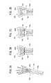
また、シャフト30の先端部には、図3及び図4Aに示すように、先端チップ40が取り付けられている。先端チップ40は、シャフト30の外径よりも太い基部側がシャフト30の外周面に固着され、この基部から先端に向かって先細りとなるテーパ状に形成されている。 Further, as shown in FIG. 3 and FIG. 4A, a
この先端チップ40は、シャフト30よりも柔軟な材料により構成されている。先端チップ40の構成材料は、特に限定されるものではないが、例えば、ウレタン樹脂やポリウレタンエラストマー、ポリエステルエラストマー、ナイロンエラストマー等のエラストマー材料により構成するとよい。また、先端チップ40は、X線造影性の造影部材が取り付けられる、又はX線造影性を有する材料が含まれるように構成されるとよい。これにより、術者は、留置デバイス14の挿入時や骨用充填材料Cの充填時に、留置デバイス14の先端部の位置を容易に認識することができる。 The
先端チップ40の外面は、収縮状態の充填用バルーン32により覆われる。柔軟性を有する先端チップ40は、充填用バルーン32を内側から傷付けないように支持する。また、先端チップ40は、充填用バルーン32を皺がなく張った状態で内側から支持するので、充填用バルーン32をスムーズに膨張させることができる。開口部40aを有する先端チップ40の内腔は、シャフト30の流路38と連通している。開口部40aは、流路38を流動してきた骨用充填材料Cを先端方向に吐出することで、充填用バルーン32をシャフト30より先端側で拡張させる。 The outer surface of the
充填用バルーン32は、伸縮性を有し、先端チップ40の外面に接触する収縮状態から、骨用充填材料Cの供給により先端チップ40から離間する拡張状態へと移行可能である。充填用バルーン32の基端部は、固定筒42により固定されており、図4Bに示すように、充填用バルーン32は、骨用充填材料Cが供給されると球形状を呈するように拡張する。この拡張状態では、シャフト30の先端及び先端チップ40が充填用バルーン32内の基端側に位置することになる。 The filling
充填用バルーン32は、空間形成用バルーン20よりも柔軟に構成されており、拡張時には大きく伸びて(弾性変形して)薄肉となる。従って、充填用バルーン32は、橈骨100内で拡張した際には、空間108の形状に応じて適宜変形した3次元形状となる。充填用バルーン32の構成材料は、特に限定されないが、ある程度の可撓性を有する材料により形成されることが好ましく、そのような材料としては、例えば、ポリエチレン、ポリプロピレン、ポリブテン、エチレン−プロピレン共重合体、エチレン−酢酸ビニル共重合体、アイオノマー、あるいはこれら二種以上の混合物等のポリオレフィンや、軟質ポリ塩化ビニル樹脂、ポリアミド、ポリアミドエラストマー、ポリエステル、ポリエステルエラストマー、ポリウレタン、フッ素樹脂等の熱可塑性樹脂、シリコーンゴム、ラテックスゴム等が使用できる。 The filling
拡張状態の充填用バルーン32は、展開操作デバイス16により簡単に割れる(破裂する)ように構成されている。この充填用バルーン32が割れることで、充填後に硬化した骨用充填材料Cが橈骨100の空間108に露出される。充填用バルーン32は、基端部が固定筒42に強固に固定されているので、割れた後も留置デバイス14との取付状態が維持され、留置デバイス14の引き抜きに伴い、橈骨100内から回収される。 The filling
固定筒42は、充填用バルーン32の基端部を囲うように取り付けられ、シャフト30との間で充填用バルーン32を挟み込んで固定する。この固定筒42は、充填用バルーン32の基端部を強固に保持するように、シャフト30の軸方向に沿って所定長さを有する。 The fixed
図3に戻り、留置デバイス14は、橈骨100内の挿入時に、シャフト30、充填用バルーン32、先端チップ40を保護する管状のシース50を備える。シース50は、固定筒42の外径よりも大きな内径の収容ルーメン52(収容部)を有し、シャフト30や充填用バルーン32を摺動自在に収容する。 Returning to FIG. 3, the indwelling
シース50は、シャフト30よりも若干短い長さ(先端チップ40から把持部34の先端付近に至る長さ)に形成されている。シース50の基端部には、径方向外側に突出する操作板50a(シース操作部)が設けられている。シース50は、術者により操作板50aが基端方向又は先端方向に操作されることで、シャフト30と相対的に進退する。充填用バルーン32は、シース50の後退によりシース50の先端から露出される。 The
留置デバイス14の把持部34は、空間形成デバイス12と同様にY型コネクタとして構成されている。把持部34の内部には、シャフト30の流路38に連通する導入空間部54が貫通形成されている。把持部34は、収容ルーメン52の内径よりも小径の外径に形成された先端筒部56と、先端筒部56の基端に連なり先端筒部56よりも大径の胴体筒部58とを有する。そのため、先端筒部56と胴体筒部58の間には、シース50の基端部に対向しシース50の後退限界を規定する段差60が形成される。 The holding
胴体筒部58は、留置デバイス14の使用時に術者が把持する部位であり、シャフト30の軸心部に一致するように形成されている。この胴体筒部58の基端側は、展開操作デバイス16や排気チューブ44を流路38に挿入可能とする挿入ポート62として構成されている。 The
挿入ポート62の基端外周面には、雄ネジ部62aが形成されており、この雄ネジ部62aに対し雌ネジ部64aを有した案内部材64が取り付けられる。案内部材64は、取付状態で導入空間部54の軸心に一致する挿入孔64bを備え、この挿入孔64bは、展開操作デバイス16(マンドレル70)の外径よりも若干大きい内径に形成される。案内部材64と把持部34との間には、弁体66が設けられる。弁体66は、展開操作デバイス16の挿入を許容及び案内する一方で、骨用充填材料Cの漏洩を防ぐ機能を有する。 A
また、胴体筒部58の側部には、斜め基端方向に突出する注入ポート68が設けられている。注入ポート68は、骨用充填材料Cを導入空間部54に導入するための導入路68aを内部に有し、その基端部には、供給装置36が着脱自在に装着される取付部(ルアーロック機構)が設けられている。 In addition, an
供給装置36は、骨用充填材料Cを充填するための装置であり、拡縮操作装置24と同様に、例えばシリンジによって構成される。供給装置36は、術者により押し子が押出し操作されることで、注入ポート68の取付部に取り付けられた先端部から骨用充填材料Cを排出する。これにより、骨用充填材料Cは、導入路68a及び導入空間部54を介してシャフト30の流路38に供給される。 The
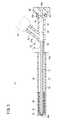
シャフト30の流路38内には、骨用充填材料Cの供給前に、排気チューブ44(気体排出部46)が配置される。図1に示すように、排気チューブ44は、細長い直線状に形成された管状部材であり、骨用充填材料Cの供給時に流路38の空気(気体)を充填用バルーン32よりも基端側に排出する機能を有する。 In the
排気チューブ44は、案内部材64の挿入孔64bから弁体66を介して挿入ポート62に挿入され、導入空間部54を通って流路38に挿入される。なお、留置デバイス14は、骨治療システム10の製品提供状態で、排気チューブ44が予め流路38内に挿入された状態となっていてもよい。 The
排気チューブ44の内部には、空気の排気路44aが軸方向に沿って貫通形成されている。排気チューブ44の先端面には、排気路44aに連なる先端開口44bが設けられ、排気チューブ44は、この先端開口44bから排気路44aに空気を流入させることができる。なお、排気路44aに連通する開口の形成箇所は、特に限定されるものではなく、排気チューブ44の先端側側面に形成されていてもよく、排気チューブ44の軸方向に沿って複数設けられていてもよい。 An
この排気チューブ44は、収縮状態の充填用バルーン32の先端内面に近接するまで挿入されるように所定の軸方向長さを有する。また、排気チューブ44は、空気を排出可能な排気路44aを備えていればよく、その外径は相当に小さく(細く)形成してよい。 The
排気チューブ44の基端部には、排気チューブ44よりも大径の操作部48が取り付けられることが好ましい。操作部48は、排気チューブ44の進出操作を容易化すると共に、排気チューブ44の挿入量を規定することが可能である。例えば、操作部48は、案内部材64の挿入孔64bの内径に一致する外径に形成され、操作部48の挿入孔64bへの嵌め込みにより排気チューブ44の先端開口44bを充填用バルーン32の近くに配置する構成とすることができる。これにより、細く形成された排気チューブ44が充填用バルーン32に接触して充填用バルーン32や排気チューブ44を傷付けることを防ぐことができる。 An
排気チューブ44を構成する材料は、骨用充填材料Cの供給圧により排気路44aが押しつぶされない程度の剛性を有するものが好ましい。この場合、例えば、シャフト18、30の構成材料で挙げたものを好適に適用することができる。但し、排気チューブ44の先端部の位置はX線透視下で確認できることが好ましいので、単独で造影性が悪い場合は、先端部に金や白金等のマーカーを設けることが好ましい。また硬化した骨用充填材料Cに対して相対移動を容易となるよう、排気チューブ44の表面は潤滑性を有することが好ましく、必要に応じて潤滑剤(挿入部材用潤滑剤)が塗布されていてもよい。潤滑剤としては、例えばシリコンオイル等が挙げられる。 The material constituting the
流路38に排気チューブ44が配置された状態で、骨用充填材料Cは、供給装置36から供給されてシャフト30の先端方向に流動する。この際、シャフト30内の空気は、骨用充填材料Cから供給圧により先端方向に向かい、排気チューブ44の先端開口44bから排気路44aに流入され、シャフト30の基端部(充填用バルーン32よりも基端側)に排出される。よって、骨用充填材料Cはスムーズに先端方向に導かれ、充填用バルーン32の内部に充填される。充填用バルーン32は、骨用充填材料Cの充填にともない、シャフト30の先端部で図4Bに示すような拡張状態となる。そして、充填された骨用充填材料Cは、所定時間(例えば、5〜15分程度)経過すると、橈骨100内に留置可能な程度まで硬化した状態となる。 In a state where the
図1に戻り、展開操作デバイス16は、上記の硬化状態の骨用充填材料Cを橈骨100の空間108に露出させるためのデバイスである。この展開操作デバイス16は、骨用充填材料Cの硬化前に挿入される挿入部材であるマンドレル70(芯金)と、骨用充填材料Cが硬化してマンドレル70を引き抜いた後に挿入される針部材80とにより構成される。 Returning to FIG. 1, the
マンドレル70は、細長い直線状に形成された棒部材である。マンドレル70は、骨用充填材料Cの充填後(充填用バルーン32の拡張後)に、術者により排気チューブ44が流路38から引き抜かれ、その代わりに留置デバイス14の内部に挿入される。これにより、マンドレル70は硬化状態の骨用充填材料Cの内部に通路72を形成する。 The
マンドレル70は、拡張した充填用バルーン32の内面に接触するまで挿入される。その結果、通路72は、把持部34(挿入ポート62)の基端部から拡張状態の充填用バルーン32まで達する直線状の空洞部に形成される。このため、マンドレル70は、長手方向の長さが留置デバイス14よりも長く、また外径が留置デバイス14の流路38の内径よりも小さく設定されている。 The
マンドレル70の長尺部71は、充填用バルーン32に対するマンドレル70の相対位置を認識することが容易となるように、X線造影性を有する材料により構成されことが好ましい。また、マンドレル70の先端部70aは、拡張状態の充填用バルーン32に接触しても割れないように、丸角に形成されているとよい。 The
マンドレル70は、挿入時に、把持部34に取り付けられた案内部材64及び弁体66により姿勢が案内される。また、先端部70aが充填用バルーン32に達した状態では、基端部が弁体66に保持されることで骨用充填材料Cの硬化までの姿勢が良好に維持される。長尺部71の基端部には、マンドレル70の進出操作を容易に行うため、マンドレル70よりも大径の操作部74が取り付けられることが好ましい。操作部74は、案内部材64の挿入孔64bの内径に一致する外径に形成されることで、マンドレル70の挿入状態で挿入孔64bに保持されるように構成されてもよい。 The posture of the
マンドレル70は、留置デバイス14への挿入後に所定時間経過して硬化した骨用充填材料Cに通路72を形成すると、術者により留置デバイス14から引き抜かれる。長尺部71の外周面は滑らかに形成されており、マンドレル70を多少振動や回転させることで、比較的容易に引き抜くことができる。なお、長尺部71は、硬化した骨用充填材料Cに対して相対移動を容易とする潤滑剤71a(挿入部材用潤滑剤)が塗布されていてもよい。潤滑剤71aとしては、例えばシリコンオイル等が挙げられる。マンドレル70の引抜き後は、通路72に対し針部材80が挿入される。 The
針部材80は、マンドレル70と同様に、細長い直線状に形成され、先端部に鋭利な針先82を有する。針部材80の外径は、マンドレル70の外径よりも多少小径に形成されており、マンドレル70によって形成された骨用充填材料Cの通路72をスムーズに通過することが可能である。針部材80の針先82は、留置デバイス14を先端方向に移動して、拡張状態の充填用バルーン32に接触することで、充填用バルーン32を簡単に割ることができる。なお、針部材80の摺動性を高めるために、針部材80の外周面には、マンドレル70と同様に潤滑剤71aが塗布されていてもよい。 Similar to the
マンドレル70や針部材80の構成材料は、特に限定されるものではないが、例えばステンレス鋼等の金属材等により構成されるとよい。また、針部材80も、X線造影性を有していることが好ましい。これにより、針部材80の進出操作時に、針先82が充填用バルーン32に達して、充填用バルーン32を割ったことを認識することができる。 Although the constituent material of the
本実施形態に係る骨治療システム10は、基本的には、以上のように構成されるものであり、次にこの骨治療システム10の作用効果について説明する。 The
以下では、骨治療システム10による骨治療の一例として、骨用充填材料Cの留置による橈骨遠位端骨折の治療を説明する。留置処置の前は、図2Bに示すように、術者が橈骨100の骨折箇所を整復し、胴体部100aと遠位端部100bを正常な位置関係とする。そして、整復後状態の橈骨100に留置処理を実施する。なお、以降の留置処置においては、X線撮影が実施され橈骨100の骨折箇所の状態をX線撮影画像でリアルタイムに確認している。 Hereinafter, as an example of bone treatment by the
留置処置では、図5Aに示すように、まず空間形成デバイス12を使用する。術者は、整復後状態を保持して皮膚を切開し、橈骨100の緻密質104に対し、空間形成デバイス12及び留置デバイス14を挿入するための孔110をドリル等により形成する。孔110は、骨折によりヒビが形成された箇所に沿って穿孔されるとよい。これにより、後に空間形成デバイス12や留置デバイス14を孔110に容易に挿入することができる。なお、橈骨100に対する孔110の穿孔方向、換言すれば空間形成デバイス12や留置デバイス14の挿入方向は、特に限定されるものではなく、骨折状況に応じて適宜設定してよい。 In the indwelling treatment, first, the
孔110の形成後は、空間形成デバイス12を孔110に挿入する。この際、空間形成用バルーン20は収縮状態となっており、空間形成デバイス12の先端部が橈骨100内に容易に挿入される。また橈骨100の内部は、骨粗鬆症により海綿質106が脆いことで、空間形成デバイス12の進出を許容する。 After forming the
術者は、図5Bに示すように、空間形成デバイス12の先端部を橈骨100の奥(孔110と反対側の緻密質104)まで挿入すると、拡張用流体を供給して空間形成用バルーン20の拡張を行う。空間形成用バルーン20は、充分な強度を有するため、拡張する際に拡張用流体の供給圧によって脆くなっている海綿質106を破砕する。これにより、橈骨100の内部には、空間形成用バルーン20の拡張量(体積)に応じた空間108が形成される。空間108の形成後は、空間形成用バルーン20を収縮して、空間形成デバイス12を橈骨100の内部から引き抜く。 As shown in FIG. 5B, when the operator inserts the distal end portion of the
次に、図6Aに示すように、空間形成デバイス12に代えて留置デバイス14を使用する。術者は、シース50の収容ルーメン52にシャフト30及び充填用バルーン32を収容した状態で、橈骨100に向けて留置デバイス14を進出させ、孔110(図5A参照)に挿入する。この際、シース50も橈骨100内に挿入することで、充填用バルーン32の損傷を回避することができ、また橈骨100に対するデバイスの挿入量を体外から認識することができる。なお、留置デバイス14の挿入では、橈骨100の外側でシース50を孔110の位置合わせに用い、シャフト30や充填用バルーン32をシース50に対し進出させて橈骨100内に挿入してもよい。 Next, as shown in FIG. 6A, an
留置デバイス14の先端部が、空間108に挿入されると、シース50の操作板50aを基端方向に後退移動させて、シャフト30の先端部(収縮状態の充填用バルーン32)を空間108内に露出させる。シース50は、基端部が把持部34の段差60に接触するまで後退操作されることで、充填用バルーン32を確実に拡張可能とする。 When the distal end portion of the
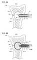
シース50を後退した後、術者は、留置デバイス14の挿入ポート62から排気チューブ44を挿入し、その先端部を充填用バルーン32の近くまで送達する。これにより、排気チューブ44の先端開口44bからシャフト30の先端付近の空気を取り込み可能となる。排気チューブ44の配置後、供給装置36を操作して、図6Bに示すように、シャフト30の流路38を通して骨用充填材料Cを充填用バルーン32に供給する。なお、以下の処置の説明では、ペースト状の骨用充填材料についてC1を付し、硬化状態(少なくとも体液で崩壊しない程度の硬化状態又はそれ以上に硬化した状態)の骨用充填材料についてC2を付す。骨用充填材料C1の供給時には、流路38内の空気が、排気チューブ44の排気路44aを介して体外に排気される。 After retracting the
充填用バルーン32は、骨用充填材料C1が内側に充填されることにより、シャフト30の先端において空間108の形状に対応して拡張していく。充填用バルーン32の拡張量は、空間108の体積に略一致する又は多少小さくなる程度に設定されるとよい。これにより、骨用充填材料C1を充填し過ぎることで、骨用充填材料C2の充填部と橈骨100の内面との間で充填用バルーン32を強く圧迫することが防止され、後の充填用バルーン32の回収を円滑に行うことができる。 The filling
充填用バルーン32の拡張後は、排気チューブ44を引き抜いて、その代わりに留置デバイス14の挿入ポート62からマンドレル70(展開操作デバイス16)を挿入する。術者は、留置デバイス14の流路38を介して、マンドレル70を先端方向に進出操作し、図7Aに示すように、先端部70aが充填用バルーン32の内面に接触することで進出を停止する。マンドレル70は、X線造影下で先端部70aの位置が確認されることで、充填用バルーン32に対し不必要に押し出される等して、骨用充填材料C1の硬化前に充填用バルーン32を割ることを防ぐことができる。 After the filling
マンドレル70の挿入後は、所定時間待機することにより骨用充填材料C1を硬化させる。骨用充填材料Cは、例えば、硬化型のCPCであれば、10分前後で体液により容易に崩壊しない程度に硬化するため、患者にとって大きな負担とはならない。 After inserting the
所定時間経過後、術者は、硬化状態の骨用充填材料C2からマンドレル70を引き抜く操作を行う。直線状に形成されたマンドレル70は、骨用充填材料C2に引っ掛かる等の不都合がなく、留置デバイス14の軸方向に沿って円滑に引き抜かれる。 After a predetermined time has elapsed, the operator performs an operation of pulling out the
マンドレル70を引き抜くと、図7Bに示すように、硬化状態の骨用充填材料C2の内部には通路72が形成される。通路72は、マンドレル70が挿入されていた留置デバイス14の挿入ポート62に通じており、術者は、挿入ポート62から針部材80を挿入することで、通路72に沿って針部材80を進出させることができる。 When the
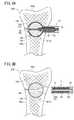
通路72は、充填用バルーン32の内面まで直線状に形成されており、術者は、通路72に沿って針部材80を円滑に進出操作し、通路72に対向する充填用バルーン32の略正中位置に針先82を簡単に接触させることができる。この針先82の接触により、充填用バルーン32は、図8Aに示すように空間108の奥側から割れる。なお、図8Aは、充填用バルーン32が破裂した直後の状態を示している。針先82は、拡張状態の充填用バルーン32の中で最も伸びている部分を刺すことになり、充填用バルーン32は、積極的に破裂が促される。これにより、硬化状態の骨用充填材料C2が空間108内に露出される。 The
伸縮性を有する充填用バルーン32は、留置デバイス14の先端側(遠位側)から割れることで、割れた膜部分(破裂片32a)がシャフト30に固定された基端部側に移動するように作用する。すなわち、破裂片32aは、骨用充填材料C2内を移動してシャフト30側に近づくことになり、骨用充填材料C2を積極的に露出させる。また、留置デバイス14は、基端部側に移動した充填用バルーン32(破裂片32a)を容易に回収することが可能となる。 The filling
骨用充填材料C2を露出した後は、図8Bに示すように、針部材80を通路72から引き抜き、さらに留置デバイス14を橈骨100内から引き抜く。これにより、橈骨100の空間108には、硬化状態の骨用充填材料C2が留置される。 After the bone filling material C2 is exposed, as shown in FIG. 8B, the
硬化状態の骨用充填材料C2は、橈骨100内周辺の骨に吸収され、その後徐々に自家骨に置換されていく。その結果、橈骨100は、胴体部100aと遠位端部100bの接合がなされる。 The bone filling material C2 in a hardened state is absorbed by the bone around the
以上のように、本実施形態に係る骨治療システム10は、流路38内の空気を充填用バルーン32よりも基端方向に流動させる気体排出部46を備えることで、流路38から空気が抜けるため骨用充填材料Cを円滑に充填することができる。また、骨用充填材料Cに空気が混じることが抑制されるので、硬化状態の骨用充填材料Cに気泡や凹凸が生じ難くなる。よって、骨用充填材料Cの脆弱化を抑えると共に、充填用バルーン32の回収を容易に行うことができる。その結果、橈骨100の空間108に対し、硬化状態の骨用充填材料C2を容易且つ精度よく留置し、骨折箇所を一層良好に治療することができる。 As described above, the
この場合、気体排出部46が排気チューブ44により構成されることで、排気チューブ44を流路38内に配置するだけで、流路38内の空気を良好に排出することができる。 In this case, since the
なお、本発明に係る骨治療システム10は、上記の構成に限定されるものではなく、種々の変形例及び応用例をとり得る。例えば、充填用バルーン32の一部を破って破裂させるための構成は、特に限定されるものではく、種々の構成を採用し得る。例えば、上述した針部材80に代わる作用部材として、先端部に加熱部を備えたデバイスを通路72に挿入し、当該加熱部により充填用バルーン32の一部を切り、破裂させてもよい。あるいは、他の作用部材として、先端部に鋏機構を備えたデバイスを通路72に挿入し、当該鋏機構により充填用バルーン32の一部を切り、破裂させてもよい。 In addition, the
以下、骨治療システム10の変形例について具体例を幾つか説明していく。なお、以降の説明において、本実施形態に係る骨治療システム10と同一の構成又は同一の機能を有する構成については、同じ符号を付しその詳細な説明を省略する。 Hereinafter, some specific examples of modified examples of the
図9に示す第1変形例に係る留置デバイス14Aの気体排出部46Aは、シャフト120の軸方向途中位置の側面に排気チューブ122を固定した構成となっている。排気チューブ122は、排気路122aと、排気路122aに連通する先端開口122b、基端開口122cとを有し、その基端部がシャフト120の壁部に取り付けられている。基端開口122cは、シャフト120の外部に開口している。従って、排気チューブ122は、骨用充填材料Cの供給時に、先端開口122bから空気を取り込み基端開口122cに排気することができる。 The
なお、例えば、排気チューブ122を比較的柔軟な材質により構成する、排気チューブ122を流路38の脇(シャフト120の内周面)に沿って配置する等すれば、骨用充填材料Cの供給後にマンドレル70を直ぐに挿入してもよい。マンドレル70は、排気チューブ122が細いため邪魔とならずに進出操作がなされる。 For example, if the
図10A〜図10Cに示す第2変形例に係るマンドレル130(展開操作デバイス16A)は、軸方向に沿って貫通路130a(排気路)を有する管体に形成され、マンドレル130自体が気体排出部46Bとして構成されている。貫通路130aは、マンドレル130の先端面に形成された先端開口130bに連通している。また、展開操作デバイス16Aは、マンドレル130の貫通路130aを移動可能な太さの針部材132を含んでもよい。 A mandrel 130 (
このマンドレル130は、図10Aに示すように、術者により骨用充填材料Cの充填前に流路38に挿入され、充填用バルーン32の内面に近接した位置に先端部が配置される。この状態で骨用充填材料Cを充填すると、貫通路130aを介して流路38の空気を排出することができる。骨用充填材料Cが充填用バルーン32を拡張した後は、図10Bに示すように、マンドレル130を進出させて、拡張状態の充填用バルーン32の内面に接触させる。そして、骨用充填材料Cの硬化状態で、図10Cに示すように、マンドレル130を引き抜くことなく、貫通路130aに沿って針部材132を進出させることで、充填用バルーン32を簡単に割ることができる。 As shown in FIG. 10A, the
なお、第2変形例に係るマンドレル130を使用しても、骨用充填材料Cの硬化後にマンドレル130を引き抜いて、針部材132を挿入する操作をしてもよいことは勿論である。また、針部材132を、軸方向に排気路を有する中空状部材とし、マンドレル130の貫通路130aに予め配置した構成としても、空気を良好に排気することができる。この場合、針部材132により充填用バルーン32の破裂操作を迅速に行うこともできる。 Of course, even if the
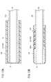
図11A及び図11Bに示す第3変形例に係る留置デバイス14Bの気体排出部46Cは、シャフト140に設けられた排気路142により構成されている。このシャフト140は、先端チップ40を備えず、シャフト140の先端部(拡径部)により充填用バルーン32を支持している。排気路142は、流路38を囲うシャフト140の壁部140aの内部に断面円形に形成された上下一対の連通空間となっている。なお、排気路142の形成数や配置箇所、形状は自由に設定してよい。 The gas discharge part 46C of the
1つの排気路142は、シャフト140の先端面に設けられた先端開口142aに連通し、先端面から基端方向に延び、固定筒42よりも基端側にて径方向外側に屈曲して、シャフト140の外周面の基端開口142bに連通している。先端開口142aは、収縮状態の充填用バルーン32に閉塞されているが、骨用充填材料Cを流路38に供給すると、流路38に内在していた空気が充填用バルーン32を押し出して開放される。従って、空気は、排気路142を介して充填用バルーン32の基端側に案内され、基端開口142bから外部(例えば、シース50の収容ルーメン52)に排出される。 One
図12Aに示す第4変形例に係る留置デバイス14Cの気体排出部46Dは、固定筒42の基端側のシャフト150(壁部150a)に空気の排気路である側孔152を設けた構成となっている。この側孔152は、空気を排出し、骨用充填材料Cを外部に漏らさない程度の充分に小さな孔径に形成することが可能である。この側孔152は、シャフト150の外周面に形成するので、加工を容易に行うことができる。側孔152よりも先端側の流路38内には、空気が残る可能性もあるが、この空気は充分に少なく硬化状態の骨用充填材料Cに殆ど影響を与えることがない。 The
図12Bに示す第5変形例に係る留置デバイス14Dは、固定筒160を短く構成して、側孔162(気体排出部46E)をシャフト164の先端部に一層近接した位置に設けている。従って、第5変形例に係る気体排出部46Eは、第4変形例に係る気体排出部46Dよりも、流路38の先端側に存在する空気を多く排気することができる。 In the indwelling device 14D according to the fifth modification shown in FIG. 12B, the fixed
図13Aに示す第6変形例に係る留置デバイス14Eは、外周面が平滑に形成されたシャフト170の先端部(取付部位)に、ガス透過膜172(気体排出部46F)を設けた構成となっている。ガス透過膜172は、空気の流通を許容する一方で、骨用充填材料Cの流通を遮断する気体透過部材としての機能を有する。このガス透過膜172としては、例えば、多孔質材(PTFE等)、メッシュ、セラミックス等が挙げられる。ガス透過膜172は、充填用バルーン32とシャフト170の間に介在して、固定筒42により固定されている。骨用充填材料Cを流路38に供給すると、流路38に内在していた空気は、充填用バルーン32を押し出してガス透過膜172に導かれる。この空気は、ガス透過膜172を通って基端方向に案内され、充填用バルーン32よりも基端側に排出される。 The
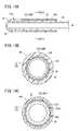
図13Bに示す第7変形例に係る留置デバイス14Fは、充填用バルーン32をコイル部材180により固定する構成となっている。コイル部材180を構成する隣接し合う線材180a(線状部)同士は、互いに所定間隔離間して充填用バルーン32を圧迫している。固定される充填用バルーン32は、線材180aの締め付け部分が谷部で隙間部分が山部になって固定されることで、シャフト184の外面と山部の内側の間に空気の排気路182(気体排出部46G)を形成している。従って、排気路182は、螺旋状を呈している。骨用充填材料Cの供給により、流路38に内在していた空気は、充填用バルーン32を押し出すことで、排気路182に導かれ、排気路182を通って螺旋状に流動して、充填用バルーン32よりも基端側に排出される。 An
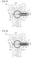
図14A及び図14Bに示す第8変形例に係る留置デバイス14Gの気体排出部46Hは、充填用バルーン32をシャフト30に固定する固定筒190の内周面に溝部192を設けた構成となっている。充填用バルーン32の固定部分33は、収縮状態において、その全周がシャフト30の周面に接触している。そして、骨用充填材料Cが供給され空気が充填用バルーン32を押し出すと、図14Bに示すように、溝部192は、固定部分33を径方向外側に弾性変形させて空気排出路194を形成する。これにより、空気を、空気排出路194を介して固定筒190よりも基端側に排出する。この溝部192は、深さや幅が適度に小さく設定されることで、空気排出路194からの骨用充填材料Cの漏れを防ぐことができる。 14A and 14B has a configuration in which a
図14Cに示す第9変形例に係る留置デバイス14Hの気体排出部46Iは、第8変形例の溝部192と反対に、シャフト200の外周面側に溝部202を設けた構成となっている。この場合、充填用バルーン32の固定部分33は、溝部202間に形成されるシャフト200の山部200aに張った状態で取り付けられる。このため、充填用バルーン32とシャフト200の間において、溝部202を通して流路38内の空気を排出することができる。 14C of the
また、本発明に係る骨治療システム10の他の変形例として、充填用バルーン32を生体吸収性の材料により構成して、骨用充填材料Cと共に充填用バルーン32も留置してもよい。充填用バルーン32は、時間経過により吸収され、硬化状態の骨用充填材料Cを展開することができる。 As another modification of the
上述した実施形態では、骨用充填材料Cが硬化状態となってから、すなわち体液で崩壊しない程度に硬化した状態となった以降に充填用バルーン32を骨内で破裂させたが、骨用充填材料Cが体液で崩壊しない程度に硬化するよりも前に充填用バルーン32を骨内で破裂させてもよい。この方法によっても、バルーンを使わずに骨用充填材料Cを骨内に導入した場合と比べて、高い治療効果が得られる。 In the above-described embodiment, the filling
上記において、本発明について好適な実施形態を挙げて説明したが、本発明は前記実施形態に限定されるものではなく、本発明の要旨を逸脱しない範囲において、種々の改変が可能なことは言うまでもない。 In the above description, the present invention has been described with reference to preferred embodiments. However, the present invention is not limited to the above-described embodiments, and various modifications can be made without departing from the scope of the present invention. Yes.
10…骨治療システム 12…空間形成デバイス
14、14A〜14H…留置デバイス
16、16A…展開操作デバイス
30、120、140、150、164、170、184、200…シャフト
32…充填用バルーン 38…流路
42、160、190…固定筒 44、122…排気チューブ
44a、122a、142、182…排気路
44b、122b、130b、142a…先端開口
46、46A〜46I…気体排出部
70、130…マンドレル 72…通路
80、132…針部材 100…橈骨
108…空間 130a…貫通路
152、162…側孔 172…ガス透過膜
180…コイル部材 192、202…溝部
C…骨用充填材料DESCRIPTION OF
Claims (8)
Translated fromJapanese前記シャフトの先端部に設けられ前記ルーメンを介して前記骨用充填材料が充填されるバルーンと、
前記骨用充填材料を前記ルーメンに充填する際に、前記ルーメン内の気体を前記バルーンよりも基端方向に流動させる気体排出部と、
前記バルーンの外側から装着されて前記シャフトに前記バルーンを固定する固定部材とを含み、
前記気体排出部は、固定されている前記バルーンの一部を前記固定部材の許容部に配置させて、前記シャフトの外面と前記バルーンの内面との間に連通部を形成することで構成される
ことを特徴とする骨治療システム。A shaft having a lumen through which a bone filler placed in a bone treatment site can be distributed;
A balloon provided at the tip of the shaft and filled with the bone filling material through the lumen;
When filling the lumen with the bone filling material, a gas discharge unit that causes the gas in the lumen to flow in the proximal direction from the balloon; and
Look includinga fixing member for fixing the balloon to the shaft is mounted from the outside of theballoon,
The gas discharge part is configured by disposing a part of the balloon that is fixed to an allowable part of the fixing member and forming a communication part between the outer surface of the shaft and the inner surface of the balloon. A bone treatment system characterized by that.
前記バルーンは、前記シャフトとの取付が維持された状態で破られることで前記骨用充填材料を露出する
ことを特徴とする骨治療システム。The bone treatment system according to claim 1, wherein
The bone treatment system, wherein the balloon is broken while being attached to the shaft to expose the bone filling material.
前記気体排出部は、前記ルーメンに挿入され先端部が前記バルーンに近接する位置に配置可能なチューブを含み、
前記チューブは、先端部に形成された開口部と、前記開口部に連なり前記気体を流通可能な排出路とを有する
ことを特徴とする骨治療システム。The bone treatment system according to claim 1 or 2,
The gas discharge partincludes a tubethat is inserted into the lumen and can be disposed at a position where a tip part is close to the balloon,
The tube has an opening formed at a distal end portion, and a discharge path that is continuous with the opening and allows the gas to flow therethrough.
前記チューブは、前記バルーンへの骨用充填材料の充填後に前記ルーメンから離脱可能である
ことを特徴とする骨治療システム。The bone treatment system according to claim 3,
The bone treatment system, wherein the tube is detachable from the lumen after the bone filling material is filled into the balloon.
前記チューブは、前記骨用充填材料の硬化に伴い前記骨用充填材料内に空洞部を形成可能な剛性を有し、
前記骨治療システムは、前記空洞部の内側を介して送達され前記バルーンを破る針部材をさらに備える
ことを特徴とする骨治療システム。The bone treatment system according to claim 3,
The tube has rigidity capable of forming a cavity in the bone filling material as the bone filling material is hardened,
The bone treatment system further includes a needle member that is delivered through the inside of the cavity and breaks the balloon.
前記針部材は、前記チューブの前記排出路に挿入可能な外径に形成されている
ことを特徴とする骨治療システム。The bone treatment system according to claim 5, wherein
The bone treatment system, wherein the needle member has an outer diameter that can be inserted into the discharge path of the tube.
前記固定部材は、筒状に形成されて前記バルーンを覆う構成であり、
前記許容部は、前記固定部材の内周面に形成された溝部である
ことを特徴とする骨治療システム。The bone treatment system according to claim 1 or 2,
Thefixing memberis a structure that would coveringthe balloon is formed in a cylindrical shape,
Bone treatment system, characterized in that saidallowance portionis a groove formed on the inner peripheral surface of the fixing member.
前記固定部材は、前記バルーンを巻回するコイル部材であり、
前記許容部は、前記コイル部材を構成する線状部の隙間である
ことを特徴とする骨治療システム。The bone treatment system according to claim 1 or 2,
Thefixing member isa coil memberthat windstheballoon ,
Bone treatment system, wherein theallowing portionis a gap between the linear portion constituting the coil member.
Priority Applications (3)
| Application Number | Priority Date | Filing Date | Title |
|---|---|---|---|
| JP2013202748AJP6151617B2 (en) | 2013-09-27 | 2013-09-27 | Bone treatment system |
| EP14182126.4AEP2853211B1 (en) | 2013-09-27 | 2014-08-25 | Bone treatment system |
| US14/497,394US20150094731A1 (en) | 2013-09-27 | 2014-09-26 | Bone treatment system |
Applications Claiming Priority (1)
| Application Number | Priority Date | Filing Date | Title |
|---|---|---|---|
| JP2013202748AJP6151617B2 (en) | 2013-09-27 | 2013-09-27 | Bone treatment system |
Publications (2)
| Publication Number | Publication Date |
|---|---|
| JP2015066148A JP2015066148A (en) | 2015-04-13 |
| JP6151617B2true JP6151617B2 (en) | 2017-06-21 |
Family
ID=51392124
Family Applications (1)
| Application Number | Title | Priority Date | Filing Date |
|---|---|---|---|
| JP2013202748AActiveJP6151617B2 (en) | 2013-09-27 | 2013-09-27 | Bone treatment system |
Country Status (3)
| Country | Link |
|---|---|
| US (1) | US20150094731A1 (en) |
| EP (1) | EP2853211B1 (en) |
| JP (1) | JP6151617B2 (en) |
Families Citing this family (3)
| Publication number | Priority date | Publication date | Assignee | Title |
|---|---|---|---|---|
| CN105286976B (en)* | 2015-09-18 | 2017-08-25 | 北京市富乐科技开发有限公司 | Puncture bone grafting system |
| US10786659B2 (en) | 2016-06-01 | 2020-09-29 | Microvention, Inc. | Reinforced balloon catheter |
| CN110897696B (en)* | 2019-12-30 | 2025-05-30 | 宁波华科润生物科技有限公司 | A multifunctional vertebral body shaping device |
Family Cites Families (22)
| Publication number | Priority date | Publication date | Assignee | Title |
|---|---|---|---|---|
| US4715378A (en)* | 1986-07-28 | 1987-12-29 | Mansfield Scientific, Inc. | Balloon catheter |
| US4821722A (en)* | 1987-01-06 | 1989-04-18 | Advanced Cardiovascular Systems, Inc. | Self-venting balloon dilatation catheter and method |
| US5100385A (en)* | 1989-01-27 | 1992-03-31 | C. R. Bard, Inc. | Fast purge balloon dilatation catheter |
| US6994687B1 (en)* | 2000-01-19 | 2006-02-07 | Cordis Neurovascular, Inc. | Inflatable balloon catheter with purge mechanism and method |
| WO2004043303A2 (en) | 2002-11-12 | 2004-05-27 | Regenex Ltd. | Expandable devices and methods for tissue expansion, regenerationand fixation |
| US6632235B2 (en)* | 2001-04-19 | 2003-10-14 | Synthes (U.S.A.) | Inflatable device and method for reducing fractures in bone and in treating the spine |
| US6932843B2 (en)* | 2002-09-25 | 2005-08-23 | Medicinelodge, Inc. | Apparatus and method for the in-situ formation of a structural prosthesis |
| US7306610B2 (en)* | 2003-03-21 | 2007-12-11 | Cana Lab Corporation | Method and device for forming a hardened cement in a bone cavity |
| TW587932B (en)* | 2003-05-21 | 2004-05-21 | Guan-Gu Lin | Removable animal tissue filling device |
| US20050216025A1 (en)* | 2004-03-22 | 2005-09-29 | Cana Lab Corporation | Device for forming a hardened cement in a bone cavity |
| EP1893109B1 (en)* | 2005-06-15 | 2017-10-04 | Joy Medical Devices Corporation | Tool and technique for continually delivering an orthopaedic paste |
| WO2007087400A2 (en)* | 2006-01-23 | 2007-08-02 | Osseon Therapeutics, Inc. | Bone cement composite containing particles in a non-uniform spatial distribution and devices for implementation |
| EP1983917B1 (en)* | 2006-01-27 | 2014-06-25 | Spinal Ventures, LLC | Low pressure delivery system for delivering a solid and liquid mixture into a target site for medical treatment |
| WO2008114483A1 (en)* | 2007-03-16 | 2008-09-25 | Olympus Terumo Biomaterials Corp. | Unit for resetting bone fracture caused by pyramidal compression |
| JP2008259810A (en)* | 2007-03-16 | 2008-10-30 | Olympus Terumo Biomaterials Corp | Unit for resetting bone fracture caused by vertebral compression |
| US7988696B2 (en)* | 2007-06-01 | 2011-08-02 | Joy Medical Devices Corporation | Perforated balloon and method for forming a hardened orthopaedic paste in a bone using same |
| WO2009084109A1 (en)* | 2007-12-28 | 2009-07-09 | Olympus Terumo Biomaterials Corp. | Unit for resetting bone fracture caused by pyramidal compression |
| JP5124550B2 (en)* | 2009-09-28 | 2013-01-23 | オリンパス株式会社 | Occlusion device |
| DE102010052323A1 (en)* | 2010-11-25 | 2012-05-31 | Heraeus Medical Gmbh | Cartridge with lockable delivery piston |
| US20140316411A1 (en)* | 2011-11-17 | 2014-10-23 | Beth Israel Deaconess Medical Center | Systems and methods for minimally invasive fracture reduction and fixation |
| US8915961B2 (en)* | 2012-06-05 | 2014-12-23 | Depuy Mitek, Llc | Methods and devices for anchoring a graft to bone |
| JP6152029B2 (en)* | 2013-09-27 | 2017-06-21 | テルモ株式会社 | Bone treatment system |
- 2013
- 2013-09-27JPJP2013202748Apatent/JP6151617B2/enactiveActive
- 2014
- 2014-08-25EPEP14182126.4Apatent/EP2853211B1/enactiveActive
- 2014-09-26USUS14/497,394patent/US20150094731A1/ennot_activeAbandoned
Also Published As
| Publication number | Publication date |
|---|---|
| JP2015066148A (en) | 2015-04-13 |
| US20150094731A1 (en) | 2015-04-02 |
| EP2853211A1 (en) | 2015-04-01 |
| EP2853211B1 (en) | 2022-03-23 |
Similar Documents
| Publication | Publication Date | Title |
|---|---|---|
| JP6152029B2 (en) | Bone treatment system | |
| KR100882365B1 (en) | Insertion devices and method of use | |
| JP4764432B2 (en) | System for placing material on bone | |
| JP5815522B2 (en) | Bone microfracture generator | |
| EP2892458B1 (en) | Instruments for controlled delivery of injectable materials into bone | |
| US20040102845A1 (en) | Methods of performing embolism-free vertebroplasty and devices therefor | |
| CN1553786A (en) | Systems and methods for treating bone | |
| JP2001293017A (en) | Orthopaedic implant, bone grafting method therefor, plasty reamer and orthopaedic kit | |
| CN108992768B (en) | Brain operation dilator and brain channel establishment method using same | |
| US20110054416A1 (en) | Material control device for inserting material into a targeted anatomical region | |
| CN101589964A (en) | Instruments for squeezing spongy bone | |
| CN102499740B (en) | Centrum balloon dilation forming system | |
| JP2013510647A (en) | Curable material delivery system and method | |
| JP6151617B2 (en) | Bone treatment system | |
| US20090005816A1 (en) | Spinal rod, insertion device, and method of using | |
| JP2015066113A (en) | Bone treatment system | |
| JP6173150B2 (en) | Bone treatment system | |
| JP2015066136A (en) | Bone treatment system | |
| JP2015066111A (en) | Bone treatment system | |
| JP2015066116A (en) | Bone treatment system | |
| JP2007260359A (en) | Method of filling bone supplementary material and filler used therein | |
| JP2007260361A (en) | Tool for filling bone compensating material, and its filling method | |
| JP2016532479A (en) | Balloon-assisted vertebral reinforcement system | |
| WO2013190666A1 (en) | Puncture instrument | |
| JP2015062539A (en) | Implant |
Legal Events
| Date | Code | Title | Description |
|---|---|---|---|
| A621 | Written request for application examination | Free format text:JAPANESE INTERMEDIATE CODE: A621 Effective date:20160225 | |
| A977 | Report on retrieval | Free format text:JAPANESE INTERMEDIATE CODE: A971007 Effective date:20161207 | |
| A131 | Notification of reasons for refusal | Free format text:JAPANESE INTERMEDIATE CODE: A131 Effective date:20161213 | |
| A601 | Written request for extension of time | Free format text:JAPANESE INTERMEDIATE CODE: A601 Effective date:20170210 | |
| A521 | Request for written amendment filed | Free format text:JAPANESE INTERMEDIATE CODE: A523 Effective date:20170315 | |
| TRDD | Decision of grant or rejection written | ||
| A01 | Written decision to grant a patent or to grant a registration (utility model) | Free format text:JAPANESE INTERMEDIATE CODE: A01 Effective date:20170425 | |
| A61 | First payment of annual fees (during grant procedure) | Free format text:JAPANESE INTERMEDIATE CODE: A61 Effective date:20170525 | |
| R150 | Certificate of patent or registration of utility model | Ref document number:6151617 Country of ref document:JP Free format text:JAPANESE INTERMEDIATE CODE: R150 | |
| R250 | Receipt of annual fees | Free format text:JAPANESE INTERMEDIATE CODE: R250 | |
| R250 | Receipt of annual fees | Free format text:JAPANESE INTERMEDIATE CODE: R250 | |
| R250 | Receipt of annual fees | Free format text:JAPANESE INTERMEDIATE CODE: R250 | |
| R250 | Receipt of annual fees | Free format text:JAPANESE INTERMEDIATE CODE: R250 | |
| R250 | Receipt of annual fees | Free format text:JAPANESE INTERMEDIATE CODE: R250 |