JP6151503B2 - Portable electronic devices - Google Patents
Portable electronic devicesDownload PDFInfo
- Publication number
- JP6151503B2 JP6151503B2JP2012229343AJP2012229343AJP6151503B2JP 6151503 B2JP6151503 B2JP 6151503B2JP 2012229343 AJP2012229343 AJP 2012229343AJP 2012229343 AJP2012229343 AJP 2012229343AJP 6151503 B2JP6151503 B2JP 6151503B2
- Authority
- JP
- Japan
- Prior art keywords
- proximity communication
- communication unit
- unit
- electronic device
- portable electronic
- Prior art date
- Legal status (The legal status is an assumption and is not a legal conclusion. Google has not performed a legal analysis and makes no representation as to the accuracy of the status listed.)
- Active
Links
Images


Classifications
- Y—GENERAL TAGGING OF NEW TECHNOLOGICAL DEVELOPMENTS; GENERAL TAGGING OF CROSS-SECTIONAL TECHNOLOGIES SPANNING OVER SEVERAL SECTIONS OF THE IPC; TECHNICAL SUBJECTS COVERED BY FORMER USPC CROSS-REFERENCE ART COLLECTIONS [XRACs] AND DIGESTS
- Y02—TECHNOLOGIES OR APPLICATIONS FOR MITIGATION OR ADAPTATION AGAINST CLIMATE CHANGE
- Y02D—CLIMATE CHANGE MITIGATION TECHNOLOGIES IN INFORMATION AND COMMUNICATION TECHNOLOGIES [ICT], I.E. INFORMATION AND COMMUNICATION TECHNOLOGIES AIMING AT THE REDUCTION OF THEIR OWN ENERGY USE
- Y02D30/00—Reducing energy consumption in communication networks
- Y02D30/70—Reducing energy consumption in communication networks in wireless communication networks
Landscapes
- Mobile Radio Communication Systems (AREA)
- Telephone Function (AREA)
Description
Translated fromJapanese本出願は、近接通信機能を有する携帯電子機器に関する。 The present application relates to a portable electronic device having a proximity communication function.
近接通信機能を有する機器が知られている。例えば、特許文献1では、バッテリからの必要な電力供給がなくなった場合にだけ、セキュリティコントローラを低消費電力で動作するモードに制御し、外部からの電磁界電力により非接触認証および決済機能を確保する携帯通信端末装置が提案されている。 Devices having a near field communication function are known. For example, in Patent Document 1, only when the necessary power supply from the battery is lost, the security controller is controlled to a mode that operates with low power consumption, and contactless authentication and settlement functions are ensured by external electromagnetic field power. Mobile communication terminal devices have been proposed.
近接通信機能を有する機器では、供給される電力の電圧によっては、近接通信機能に関連する通信部、記憶部等の動作が不安定になり、近接通信機能が正常に動作しないおそれがあった。上記のことから、近接通信機能が正常に動作する可能性を高めることができる携帯電子機器に対するニーズがある。 In a device having a near field communication function, depending on the voltage of the supplied power, operations of the communication unit, the storage unit, and the like related to the near field communication function may become unstable, and the near field communication function may not operate normally. From the above, there is a need for a portable electronic device that can increase the possibility that the near field communication function operates normally.
1つの態様において、携帯電子機器は、近接通信部と、前記近接通信部が通信する際に用いる情報を記憶する記憶部と、を備え、前記近接通信部は、基地局との通信の動作周期に基づいて、前記記憶部へのアクセスを制御される。In one aspect, the portable electronic device includes a proximity communication unit and a storage unit that stores information used when the proximity communication unit communicates, and the proximity communication unitoperates an operation cycle of communication with a base station. Based on the above, access to the storage unit is controlled.
本発明を実施するための実施形態を、図面を参照しつつ詳細に説明する。以下では、携帯電子機器の例として、携帯電話について説明する。 Embodiments for carrying out the present invention will be described in detail with reference to the drawings. Hereinafter, a mobile phone will be described as an example of the mobile electronic device.
(実施形態1)
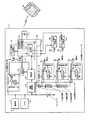
図1を参照しながら、第1の実施形態に係る携帯電子機器11の構成について説明する。図1は、携帯電子機器11の構成を示すブロック図である。携帯電子機器11は、近接通信機能を有する携帯電話である。図1に示すように、携帯電子機器11は、近接通信部110と、セキュア領域(記憶部)121および122と、バッテリ131と、制御部141と、電源管理部142と、ロック保持部143と、低電圧検出部144と、通信部151と、カメラ152と、低損失レギュレータ161および162と、遅延回路171および172とを含む。携帯電子機器11は、一般的な携帯電話が備えるその他の要素を含んでもよい。(Embodiment 1)
The configuration of the portable
近接通信部110は、近接通信(非接触通信)を実現する。近接通信は、数センチ〜1メートル程度の近距離で行われる通信である。近接通信を実現するための技術は、例えば、NFC(Near Field Communication)フォーラムにて仕様が策定された技術、その他のRFID(Radio Frequency IDentification)技術等を含む。近接通信部110は、例えば、電磁誘導により通信を行う。近接通信部110は、携帯電子機器11の電源がOFFのとき(制御部141等の他の機能部が停止しているとき)にも近接通信を行うことができるように構成されてもよい。 The
近接通信部110は、ベースバンド処理部111と、検波回路112と、アンテナ113と、スイッチ114とを含む。ベースバンド処理部111は、近接通信部110を制御する。ベースバンド処理部111は、ベースバンド処理等の近接通信のための各種信号処理を行う機能に加えて、スイッチ114を制御する機能を有する。検波回路112は、アンテナ113による信号の受信を検出する。アンテナ113は、機器20等の近接通信に対応した他の機器との間で信号を送受信する。機器20は、例えば、リーダ、ライタ、またはリーダ/ライタである。スイッチ114は、近接通信部110のロックを設定または解除する。ロックが設定されている場合、近接通信部110は、近接通信を行わず、セキュア領域121および122に対するアクセス(読み書き)も行わない。
セキュア領域121および122は、近接通信部110が通信する際に用いる信号(近接通信によってやりとりされる情報)を記憶する。セキュア領域121および122に記憶される情報は、例えば、認証のための情報、決定のための情報等を含む。セキュア領域121および122に記憶される情報は、例えば、暗号化技術によって、安全に保護される。セキュア領域121および122は、異なる場所に設けられてもよい。セキュア領域121および122は、それぞれ、近接通信専用の記憶デバイス、SIM(Subscriber Identity Module)カード、各種のアプリやデータの記憶に用いられる本体メモリ、取り外し可能なメモリカード等のいずれの場所に設けられてもよい。 The
バッテリ131は、携帯電子機器11の各部に電力を供給する。バッテリ131は、充電可能であってもよい。バッテリ131は、取り外し可能であってもよい。 The battery 131 supplies power to each part of the portable
制御部141は、携帯電子機器11を全体制御する。制御部141は、各種制御を実行するための演算処理装置を有する。演算処理装置は、例えば、CPU(Central Processing Unit)、SoC(System−on−a−chip)、MCU(Micro Control Unit)、及びFPGA(Field−Programmable Gate Array)を含むが、これらに限定されない。 The
電源管理部142は、バッテリ131の電力が効率よく利用され、長持ちするように、各部への電力供給を管理する。電源管理部142は、バッテリ131の充電を管理する機能を有してもよい。 The
ロック保持部143は、近接通信部110のロックを保持する。具体的には、ロック保持部143は、制御部141によって近接通信部110のロックを指示されると、ベースバンド処理部111に対して近接通信部110のロックを指示する信号の送出を開始する。そして、ロック保持部143は、制御部141によって近接通信部110のロック解除を指示されると、近接通信部110のロックを指示する信号の送出を停止する。制御部141からロック保持部143への指示は、例えば、近接通信機能の有効化または無効化を指示する利用者の操作に応じて実行される。 The
低電圧検出部144は、バッテリ131から供給される電力B1の電圧(以下、「バッテリ電圧」という)に基づいて、近接通信部110によるセキュア領域121および122へのアクセスを制御する。具体的には、低電圧検出部144は、バッテリ電圧が閾値より低いかを判定する。バッテリ電圧が閾値より低い場合、低電圧検出部144は、ベースバンド処理部111に対して近接通信部110のロックを指示する信号を送出する。バッテリ電圧が閾値より低くない場合、低電圧検出部144は、近接通信部110のロックを指示する信号をベースバンド処理部111に対して送出しない。低電圧検出部144がバッテリ電圧との比較に用いる閾値は、近接通信部110と、セキュア領域121および122とが安定して動作する電圧(以下、「必要動作電圧」という)である。 The low voltage detection unit 144 controls access to the
バッテリ131の残量が減少し、バッテリ電圧が必要動作電圧を下回ると、ベースバンド処理部111がセキュア領域121または122へ正常にアクセスできない等の障害が発生するおそれがある。バッテリ131の残量が減少しつつあるときに通信部151等の負荷が動作したときにも、バッテリ電圧が必要動作電圧を一時的に下回り、ベースバンド処理部111がセキュア領域121または122へ正常にアクセスできない等の障害が発生するおそれがある。バッテリ電圧が必要動作電圧を下回る前に低電圧検出部144が近接通信部110をロックすることにより、このような障害が発生する可能性を低くすることができる。 When the remaining amount of the battery 131 decreases and the battery voltage falls below the required operating voltage, there is a possibility that a failure such as the
携帯電子機器11が、電源がOFFのときにも近接通信を行うことができるように構成される場合、電源がOFFであっても、暗電流または近接通信の利用によってバッテリ131の電力が消費され、バッテリ電圧が必要動作電圧を下回ることがある。そのため、このような構成が採られる場合、低電圧検出部144は、電源がOFFであっても、少なくともバッテリ電圧が必要動作電圧を下回るまでは動作するように構成される。 When the portable
通信部151は、通信キャリアの基地局と無線通信を行う。通信部151がサポートする通信方式は、例えば、LTE(Long Term Evolution)、W−CDMA(Wideband Code Division Multiple Access)、CDMA2000、PDC(Personal Digital Cellular)、GSM(登録商標)(Global System for Mobile Communications)、PHS(Personal Handy-phone System)、WiMAX(Worldwide Interoperability for Microwave Access)等を含むがこれに限定されない。通信部151は、IEEE802.11、Bluetooth(登録商標)等の比較的近距離で通信が行われる通信方式をサポートしてもよい。通信部151は、複数の通信方式をサポートしてもよい。 The
カメラ152は、撮影範囲の画像を電子的に取得する。通信部151およびカメラ152は、バッテリ131の電力を消費する負荷である。 The
低損失レギュレータ(Low Drop Out regulator)161および162は、バッテリ131から供給される電力の電圧を、近接通信部110と、セキュア領域121および122とが動作する電圧へ変換する。低損失レギュレータ161は、変換後の電力P1を近接通信部110およびセキュア領域121へ供給する。低損失レギュレータ162は、変換後の電力P2をセキュア領域122へ供給する。低損失レギュレータ161および162による電力の供給は、検波回路112が信号を検出していることを示す信号(以下、「検出信号」という)が低損失レギュレータ161および162に入力されている間、すなわち、近接通信が可能な間に行われる。 Low drop out regulators 161 and 162 convert the voltage of the power supplied from the battery 131 into a voltage at which the
遅延回路171は、検波回路112から送出される検出信号を遅延させる。遅延回路171によって遅延された検出信号は、低損失レギュレータ161および遅延回路172に出力される。遅延回路172は、遅延回路171から入力された検出信号をさらに遅延させる。遅延回路172によって遅延された検出信号は、低損失レギュレータ162に出力される。 The delay circuit 171 delays the detection signal transmitted from the detection circuit 112. The detection signal delayed by the delay circuit 171 is output to the low loss regulator 161 and the delay circuit 172. The delay circuit 172 further delays the detection signal input from the delay circuit 171. The detection signal delayed by the delay circuit 172 is output to the low loss regulator 162.
このように遅延回路171が検出信号を遅延させることにより、近接通信部110およびセキュア領域121へ電力P1の供給が開始されるタイミングは、検波回路112が信号を検出するタイミングよりも僅かに遅れる。また、遅延回路172が検出信号を遅延させることにより、セキュア領域122へ電力P2の供給が開始されるタイミングは、さらに遅れる。 Thus, when the delay circuit 171 delays the detection signal, the timing at which the supply of the power P1 to the near
近接通信部110と、セキュア領域121および122とへの電力供給が開始されるとき、突入電流によりバッテリ電圧が一時的に低下することがある。このため、バッテリ電圧が必要動作電圧を一時的に下回り、ベースバンド処理部111がセキュア領域121または122へ正常にアクセスできない等の障害が発生するおそれがある。このような状況は、バッテリ131の残量が比較的低い場合に発生しやすい。 When power supply to the near
遅延回路172により、セキュア領域122への電力供給が開始されるタイミングを、近接通信部110およびセキュア領域121への電力供給が開始されるタイミングよりも遅らせることにより、突入電流を分散させることができる。さらに、遅延回路171により、近接通信部110およびセキュア領域121への電力供給が開始されるタイミングを、検波回路112で信号が検出されるタイミングよりも遅らせることにより、近接通信部110への電源の投入をより緩やかにすることができる。その結果、突入電流によるバッテリ電圧の低下が減少し、障害が発生する可能性を低くすることができる。 By delaying the timing at which power supply to the
図2を参照しながら、低電圧検出部144の動作について説明する。図2は、低電圧検出部144の動作を示すフローチャートである。低電圧検出部144は、図2に示す動作を繰り返して実行する。 The operation of the low voltage detection unit 144 will be described with reference to FIG. FIG. 2 is a flowchart showing the operation of the low voltage detection unit 144. The low voltage detection unit 144 repeatedly executes the operation shown in FIG.
図2に示すように、バッテリ電圧が閾値より低い場合(ステップS101,Yes)、低電圧検出部144は、出力をONにする(ステップS102)。低電圧検出部144の出力がONになるということは、低電圧検出部144から近接通信部110に対してロックの指示がなされることを意味する。 As shown in FIG. 2, when the battery voltage is lower than the threshold value (Yes at Step S101), the low voltage detection unit 144 turns on the output (Step S102). The fact that the output of the low voltage detection unit 144 is ON means that the lock instruction is issued from the low voltage detection unit 144 to the
バッテリ電圧が閾値より低くない場合(ステップS101,No)、低電圧検出部144は、出力をOFFにする(ステップS103)。低電圧検出部144の出力がOFFになるということは、低電圧検出部144からは、近接通信部110に対してロックの指示がなされないことを意味する。この場合でも、ロック保持部143から近接通信部110に対してロックの指示がなされることはありうる。 When the battery voltage is not lower than the threshold value (No at Step S101), the low voltage detection unit 144 turns off the output (Step S103). That the output of the low voltage detection unit 144 is OFF means that the low voltage detection unit 144 does not instruct the
図3および図4を参照しながら、実施形態の効果について説明する。図3は、遅延回路172を備えない場合における近接通信部110の起動時の電圧降下の例を示す図である。図4は、遅延回路172を備える場合における近接通信部110の起動時の電圧降下の例を示す図である。図3および図4において、電流Aは、低損失レギュレータ161から近接通信部110およびセキュア領域121へ供給される電力P1の電流値であり、電流Bは、低損失レギュレータ162からセキュア領域122へ供給される電力P2の電流値である。 The effects of the embodiment will be described with reference to FIGS. 3 and 4. FIG. 3 is a diagram illustrating an example of a voltage drop when the
図3に示す例では、突入電流が流れる間隔が約4μsしかないため、電力P2の電圧が大きく低下している。この結果、ベースバンド処理部111は、電力P2が供給されるセキュア領域122へ正常にアクセスできない等の障害が発生する可能性がある。具体的な事例として、たとえば、セキュア領域122に供給される電力P2の電圧が低くなると、セキュア領域122からベースバンド処理部111に対して送出する信号の電圧も低くなってしまう可能性がある。したがって、セキュア領域122は、ベースバンド処理部111に信号を送出したつもりでも、当該信号の電圧が低いために、ベースバンド処理部111が検出できない可能性がある。このようにして、ベースバンド処理部111が、セキュア領域122へ正常にアクセスできないという障害が発生する可能性があった。 In the example shown in FIG. 3, the interval of the inrush current is only about 4 μs, so the voltage of the power P2 is greatly reduced. As a result, there is a possibility that the
一方、図4に示す例では、遅延回路172により、突入電流が流れる間隔が82.5μsまで拡がっている。このため、電力P2の電圧低下は、図3の場合よりも低減されている。この結果、電力P2が供給されるセキュア領域122に関する障害が発生する可能性は低くなっている。 On the other hand, in the example shown in FIG. 4, the delay circuit 172 extends the interval at which the inrush current flows to 82.5 μs. For this reason, the voltage drop of the electric power P2 is reduced compared with the case of FIG. As a result, the possibility that a failure related to the
上述したように、携帯電子機器11は、低電圧検出部144により、バッテリ電圧の低下を検出する。このため、携帯電子機器11は、バッテリ電圧が必要動作電圧を下回るまでバッテリ131の残量が低下する前に、近接通信部110と、セキュア領域121および122とをロックし、障害が発生する可能性を低くすることができる。さらに、携帯電子機器11は、遅延回路171および172により、近接通信部110と、セキュア領域121および122とに電力供給が開始される際の突入電流を分散させる。このため、携帯電子機器11は、バッテリ電圧が必要動作電圧を下回るまでバッテリ131の残量が低下する前においても、バッテリ電圧の一時的な低下を抑制し、障害が発生する可能性を低くすることができる。 As described above, the portable
なお、上述の実施形態においては、電力P2の電圧が低下する場合について説明したが、実施形態はこれに限定されない。たとえば、同様の方法によって、電力P1の電圧の低下も低減することが可能となり、この場合、ベースバンド処理部111がセキュア領域122に対して送出する信号が、セキュア領域122によって検出できなくなる可能性を低くすることができる。 In the above-described embodiment, the case where the voltage of the power P2 is reduced has been described. However, the embodiment is not limited to this. For example, a decrease in the voltage of the power P1 can be reduced by the same method. In this case, the signal transmitted from the
(実施形態2)
他の実施形態について説明する。図5は、携帯電子機器12の構成を示すブロック図である。携帯電子機器12は、セキュア領域(記憶部)123と、低損失レギュレータ163と、遅延回路173と、信号線L1とをさらに有する点において、携帯電子機器11と相違する。(Embodiment 2)
Another embodiment will be described. FIG. 5 is a block diagram showing a configuration of the portable
セキュア領域123は、近接通信部110が通信する際に用いる信号(近接通信によってやりとりされる情報)を記憶する。セキュア領域123に記憶される情報は、例えば、認証のための情報、決定のための情報等を含む。セキュア領域123に記憶される情報は、例えば、暗号化技術によって、安全に保護される。セキュア領域123は、近接通信専用の記憶デバイス、SIMカード、各種のアプリやデータの記憶に用いられる本体メモリ、取り外し可能なメモリカード等のいずれの場所に設けられてもよい。 The secure area 123 stores a signal (information exchanged by proximity communication) used when the
低損失レギュレータ163は、バッテリ131から供給される電力の電圧をセキュア領域123が動作する電圧へ変換し、変換後の電力P3をセキュア領域123へ供給する。低損失レギュレータ163による電力の供給は、検波回路112から送出される検出信号が低損失レギュレータ163に入力されている間、すなわち、近接通信が可能な間に行われる。 The low-loss regulator 163 converts the voltage of the power supplied from the battery 131 into a voltage at which the secure area 123 operates, and supplies the converted power P3 to the secure area 123. The power supply by the low loss regulator 163 is performed while the detection signal transmitted from the detection circuit 112 is input to the low loss regulator 163, that is, while proximity communication is possible.
遅延回路173へは、検波回路112から送出され、遅延回路171および遅延回路172によって遅延された検出信号が入力される。遅延回路173は、遅延回路172から入力された検出信号をさらに遅延させる。遅延回路173によって遅延された検出信号は、低損失レギュレータ163に出力される。このように遅延回路173が検出信号を遅延させることにより、セキュア領域123への電力P3の供給が開始されるタイミングは、セキュア領域122への電力P2の供給が開始されるタイミングよりも、さらに遅れる。 The detection signal sent from the detection circuit 112 and delayed by the delay circuit 171 and the delay circuit 172 is input to the delay circuit 173. The delay circuit 173 further delays the detection signal input from the delay circuit 172. The detection signal delayed by the delay circuit 173 is output to the low loss regulator 163. As described above, the delay circuit 173 delays the detection signal, whereby the timing at which the supply of the power P3 to the secure area 123 is started is further delayed than the timing at which the supply of the power P2 to the
遅延回路173により、セキュア領域123への電力供給が開始されるタイミングを、セキュア領域122への電力供給が開始されるタイミングよりも遅らせることにより、突入電流を分散させることができる。すなわち、携帯電子機器12においては、近接通信部110およびセキュア領域121への電力供給が開始された後、遅延回路172による遅延の分だけ遅れて、セキュア領域122への電力供給が開始される。その後、遅延回路173による遅延の分だけ遅れて、セキュア領域123への電力供給が開始される。 By delaying the timing at which power supply to the secure region 123 is started by the delay circuit 173 from the timing at which power supply to the
携帯電子機器12においては、セキュア領域123が増えたために、近接通信を開始する際の突入電流の総量が増大しているが、遅延回路173により、増大した分の突入電流が発生するタイミングが遅延されている。このため、突入電流が分散し、突入電流によるバッテリ電圧の低下が低減されている。この結果、バッテリ電圧の一時的な低下による障害が発生する可能性が低くなっている。 In the mobile
このように、セキュア領域の数が増えても、遅延回路を増やすことにより、近接通信を開始する際の突入電流を分散させ、バッテリ電圧の一時的な低下による障害が発生する可能性を低くすることができる。 In this way, even if the number of secure areas increases, by increasing the number of delay circuits, the inrush current at the time of starting proximity communication is distributed, and the possibility of a failure due to a temporary drop in battery voltage is reduced. be able to.
信号線L1は、制御部141による指示をベースバンド処理部111へ向けて伝送する。具体的には、携帯電子機器12において、制御部141は、近接通信部110およびセキュア領域121〜123以外の負荷の動作状況を監視する。そして、バッテリ電圧の低下が生じる可能性が高い場合には、制御部141は、信号線L1を介して、ベースバンド処理部111に対して近接通信部110のロックを指示する信号を送出する。 The signal line L1 transmits an instruction from the
例えば、図6に示すように、通信部151が基地局と通信を行うための動作には、動作周期がある。この動作周期は、待受状態のように通信の頻度が低い場合には長くなり、通話時のように大量の情報を送受信する場合には短くなる。通信部151のような負荷が、動作を開始する際には、突入電流が発生し、バッテリ電圧の一時的な低下による障害が発生する可能性がある。 For example, as shown in FIG. 6, the operation for the
そこで、制御部141は、通信部151のような負荷の動作周期が最低基準周期よりも短い場合には、ベースバンド処理部111に対して近接通信部110のロックを指示する信号を送出する。これにより、バッテリ電圧の一時的な低下による障害が発生する可能性を低くすることができる。 Therefore, when the operation cycle of the load such as the
最低基準周期は、例えば、セキュア領域121〜123に対する情報の読み書きに要する時間よりも十分に長く設定される。このような設定により、セキュア領域121〜123に対する正常なアクセスができない障害が発生する可能性を低くすることができる。最低基準周期は、監視対象の負荷毎に異なってもよい。最低基準周期と比較される動作周期は、直近の所定回数の動作周期の平均値、中央値、最大値、最小値等の統計的な値であってもよい。 For example, the minimum reference period is set sufficiently longer than the time required to read / write information from / to the secure areas 121-123. With such a setting, the possibility of a failure that prevents normal access to the secure areas 121 to 123 can be reduced. The minimum reference period may be different for each load to be monitored. The operation period compared with the lowest reference period may be a statistical value such as an average value, median value, maximum value, minimum value, etc. of the most recent predetermined number of operation periods.
制御部141は、動作周期に基づいて負荷が次に動作するタイミングを予測し、現在から予測したタイミングまでの期間が閾値よりも短い場合に、ベースバンド処理部111に対して近接通信部110のロックを指示する信号を送出してもよい。閾値は、例えば、セキュア領域121〜123に対する情報の読み書きに要する時間よりも十分に長い時間である。すなわち、制御部141は、負荷の動作開始による突入電流の発生までに十分に時間的な余裕があると判定される場合にのみ、近接通信部110の動作を許してもよい。このような構成により、バッテリ電圧の一時的な低下による障害が発生する可能性をさらに低くすることができる。 The
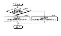
図7を参照しながら、制御部141の動作について説明する。図7は、制御部141の動作を示すフローチャートである。制御部141は、図7に示す動作を繰り返して実行する。制御部141は、図7に示す動作と並行して、他の動作を実行してもよい。 The operation of the
図7に示すように、動作周期が最低基準周期より短い場合(ステップS201,Yes)、制御部141は、ベースバンド処理部111に対する出力をONにする(ステップS202)。制御部141がベースバンド処理部111に対する出力をONにするということは、制御部141から近接通信部110に対してロックの指示がなされることを意味する。 As shown in FIG. 7, when the operation cycle is shorter than the minimum reference cycle (step S201, Yes), the
動作周期が最低基準周期より短くない場合(ステップS201,No)、制御部141は、ベースバンド処理部111に対する出力をOFFにする(ステップS203)。制御部141がベースバンド処理部111に対する出力をOFFにするということは、制御部141からは、近接通信部110に対してロックの指示がなされないことを意味する。この場合でも、ロック保持部143または低電圧検出部144から近接通信部110に対してロックの指示がなされることはありうる。 When the operation cycle is not shorter than the minimum reference cycle (No at Step S201), the
上述したように、セキュア領域の数に応じて遅延回路を増やすことにより、セキュア領域が増えても、突入電流を分散させ、障害が発生する可能性を低くすることができる。また、制御部141は、近接通信部110およびセキュア領域121〜123以外の負荷の動作状況を監視し、動作周期が最低基準周期よりも短い場合に近接通信部110をロックする。このような制御によっても、バッテリ電圧の一時的な低下を抑制し、障害が発生する可能性を低くすることができる。 As described above, by increasing the number of delay circuits in accordance with the number of secure areas, even if the secure areas increase, it is possible to disperse the inrush current and reduce the possibility of failure. In addition, the
本出願の開示する実施形態は、発明の要旨及び範囲を逸脱しない範囲で変更することができる。さらに、本出願の開示する実施形態及びその変形例は、適宜組み合わせることができる。 Embodiment which this application discloses can be changed in the range which does not deviate from the summary and range of invention. Furthermore, the embodiment disclosed in the present application and its modifications can be combined as appropriate.
また、上述の実施形態においては、セキュア領域121(P1)、セキュア領域122(P2)、セキュア領域123(P3)の順番で電力が供給されるが、実施形態はこれに限定されない。 In the above-described embodiment, power is supplied in the order of the secure area 121 (P1), the secure area 122 (P2), and the secure area 123 (P3). However, the embodiment is not limited to this.
たとえば、遅延回路171、遅延回路172および遅延回路173が、図5に示すように別々のディスクリート半導体によって構成されずに信号出力部を3つ備える一つの遅延制御部によって構成され、さらに、機器20が携帯電子機器12と近接通信を開始する際に、携帯電子機器12に対して、セキュア領域121、セキュア領域122、セキュア領域123のうち、いずれのセキュア領域と通信をしたいかを要求する構成であってもよい。 For example, the delay circuit 171, the delay circuit 172, and the delay circuit 173 are configured by one delay control unit including three signal output units without being configured by separate discrete semiconductors as shown in FIG. When starting proximity communication with the portable
このように構成されることによって、いずれのセキュア領域と通信したいかの要求を、機器20からベースバンド処理部111を介して受け付けた遅延制御部は、要求に該当するセキュア領域へ電力を供給する低損失レギュレータに最初に信号を出力する。 With this configuration, the delay control unit that has received a request for communication with any secure region from the device 20 via the
つまり、たとえば、機器20がセキュア領域123に記憶された情報に基づく通信を、近接通信が開始される際に要求してきた場合、当該要求に応じて、遅延制御部は、低損失レギュレータ163に最初に信号を出力することによって、セキュア領域121、セキュア領域122よりも早いタイミングで、セキュア領域123に電力(P3)を供給することが出来る。 That is, for example, when the device 20 requests communication based on the information stored in the secure area 123 when the proximity communication is started, the delay control unit first requests the low loss regulator 163 in response to the request. Can output power (P3) to the secure area 123 at an earlier timing than the secure area 121 and the
このようにして、機器20からの要求に応じて、セキュア領域への電力の供給の順番、換言すれば電力を供給する遅延の順番を、遅延制御部が変更可能としてもよい。 In this way, in response to a request from the device 20, the delay control unit may be able to change the order of power supply to the secure area, in other words, the order of delay in supplying power.
上記の実施形態では、携帯電子機器の例として、携帯電話について説明したが、添付の請求項に係る装置は、携帯電話に限定されない。添付の請求項に係る装置は、携帯電話以外の携帯電子機器であってもよい。携帯電子機器は、例えば、タブレット、携帯型パソコン、デジタルカメラ、メディアプレイヤ、電子書籍リーダ、ナビゲータ、及びゲーム機を含むが、これらに限定されない。 In the above embodiment, a mobile phone has been described as an example of the mobile electronic device, but the device according to the appended claims is not limited to the mobile phone. The device according to the appended claims may be a mobile electronic device other than a mobile phone. Examples of the portable electronic device include, but are not limited to, a tablet, a portable personal computer, a digital camera, a media player, an electronic book reader, a navigator, and a game machine.
添付の請求項に係る技術を完全かつ明瞭に開示するために特徴的な実施形態に関し記載してきた。しかし、添付の請求項は、上記実施形態に限定されるべきものでなく、本明細書に示した基礎的事項の範囲内で当該技術分野の当業者が創作しうるすべての変形例及び代替可能な構成を具現化するように構成されるべきである。 The characterizing embodiments have been described in order to fully and clearly disclose the technology according to the appended claims. However, the appended claims should not be limited to the above-described embodiments, but all modifications and alternatives that can be created by those skilled in the art within the scope of the basic matters shown in this specification. Should be configured to embody such a configuration.
11、12 携帯電子機器
110 近接通信部
111 ベースバンド処理部
112 検波回路
113 アンテナ
114 スイッチ
121〜123 セキュア領域(記憶部)
131 バッテリ
141 制御部
142 電源管理部
143 ロック保持部
144 低電圧検出部
151 通信部
152 カメラ
161〜163 低損失レギュレータ
171〜173 遅延回路
20 機器11, 12 Portable
Claims (7)
Translated fromJapanese前記近接通信部が通信する際に用いる情報を記憶する記憶部と、を備え、
前記近接通信部は、供給される電力の電圧および基地局との通信の動作周期に基づいて、前記記憶部へのアクセスを許可される携帯電子機器。Proximity communication unit,
A storage unit for storing information used when the proximity communication unit communicates,
The proximity communication unit is a portable electronic device that isallowed to access the storage unit based ona voltage of supplied power and an operation cycle of communication with a base station.
前記バッテリから前記近接通信部へ電力の供給が開始されるタイミングと前記バッテリから前記記憶部へ電力の供給が開始されるタイミングとを異ならせる回路と、を備える請求項3に記載の携帯電子機器。Battery,
The portable electronic device according to claim 3, further comprising: a circuit that makes a timing at which power supply from the battery is started to the proximity communication unit different from a timing at which power supply from the battery to the storage unit is started. .
前記第二の遅延回路からの信号に基づいて前記記憶部に電力を供給する第二の電力変換部と、を備える請求項5に記載の携帯電子機器。A first power converter that supplies power to the proximity communication unit based on a signal from the first delay circuit;
The portable electronic device according to claim 5, further comprising: a second power conversion unit that supplies power to the storage unit based on a signal from the second delay circuit.
Priority Applications (1)
| Application Number | Priority Date | Filing Date | Title |
|---|---|---|---|
| JP2012229343AJP6151503B2 (en) | 2012-10-16 | 2012-10-16 | Portable electronic devices |
Applications Claiming Priority (1)
| Application Number | Priority Date | Filing Date | Title |
|---|---|---|---|
| JP2012229343AJP6151503B2 (en) | 2012-10-16 | 2012-10-16 | Portable electronic devices |
Publications (2)
| Publication Number | Publication Date |
|---|---|
| JP2014082644A JP2014082644A (en) | 2014-05-08 |
| JP6151503B2true JP6151503B2 (en) | 2017-06-21 |
Family
ID=50786449
Family Applications (1)
| Application Number | Title | Priority Date | Filing Date |
|---|---|---|---|
| JP2012229343AActiveJP6151503B2 (en) | 2012-10-16 | 2012-10-16 | Portable electronic devices |
Country Status (1)
| Country | Link |
|---|---|
| JP (1) | JP6151503B2 (en) |
Family Cites Families (9)
| Publication number | Priority date | Publication date | Assignee | Title |
|---|---|---|---|---|
| JP2005352767A (en)* | 2004-06-10 | 2005-12-22 | Olympus Corp | Information device |
| JP3963470B2 (en)* | 2004-11-09 | 2007-08-22 | 株式会社東芝 | Mobile terminal and control method of the terminal |
| JP2006165787A (en)* | 2004-12-03 | 2006-06-22 | Kyocera Corp | Information processing apparatus and information notification method |
| JP2006203545A (en)* | 2005-01-20 | 2006-08-03 | Matsushita Electric Ind Co Ltd | Mobile terminal device |
| JP4974143B2 (en)* | 2006-10-30 | 2012-07-11 | 京セラ株式会社 | Mobile communication terminal |
| JP2009037566A (en)* | 2007-08-03 | 2009-02-19 | Ricoh Co Ltd | Information processing system, information processing device, portable terminal device, information processing method, and information processing program |
| JP4520519B2 (en)* | 2008-05-26 | 2010-08-04 | 富士通株式会社 | Mobile device with IC card function |
| FR2942365A1 (en)* | 2009-02-13 | 2010-08-20 | St Microelectronics Rousset | COMMUNICATION DEVICE INCLUDING BATTERY AND NEAR FIELD COMMUNICATION MODULE |
| CN101894290B (en)* | 2010-04-06 | 2015-07-08 | 上海复旦微电子集团股份有限公司 | Non-contact communication device |
- 2012
- 2012-10-16JPJP2012229343Apatent/JP6151503B2/enactiveActive
Also Published As
| Publication number | Publication date |
|---|---|
| JP2014082644A (en) | 2014-05-08 |
Similar Documents
| Publication | Publication Date | Title |
|---|---|---|
| US9979224B2 (en) | Integrated circuit for wireless charging and operating method thereof | |
| KR102233180B1 (en) | Systems and methods for smart wireless charging | |
| US10284026B2 (en) | Power supply device that supplies power to power receiving device in contactless manner, method of controlling power supply device, and storage medium | |
| US20160380467A1 (en) | Managing the output power of a wireless charger | |
| US20120261998A1 (en) | Power control apparatus, power control method, and program | |
| US9223370B2 (en) | Near field communication device operating in multiple battery modes and power management method of electronic apparatus comprising the same | |
| US9307490B2 (en) | Method for controlling bluetooth device for power conservation | |
| KR102186552B1 (en) | Apparatus and method for controlling communication module | |
| CN104145510A (en) | Energy Efficient Maximization of Network Connections | |
| US9774209B2 (en) | Selective power distribution during wireless charging | |
| WO2018201874A1 (en) | Method and network site device for adjusting terminal capability and terminal | |
| US9037086B2 (en) | Method for controlling bluetooth device for power conservation | |
| CN109426324B (en) | Power-on control method, AP chip and mobile terminal | |
| US20150089260A1 (en) | Electronic Apparatus, Method, and Storage Medium | |
| KR101755125B1 (en) | Wireless power transmitting device and operating method thereof | |
| US9973029B2 (en) | Wireless power transmission/reception apparatus | |
| US8897736B2 (en) | Mobile communication terminal device | |
| US9673866B2 (en) | Communication system and communication device | |
| JP6151503B2 (en) | Portable electronic devices | |
| JP6038587B2 (en) | Portable electronic devices | |
| US20140059366A1 (en) | Electronic device and control method | |
| JP2009094883A (en) | Auxiliary power system for cellular phone | |
| EP4239451A1 (en) | Network device energy-saving method and network device | |
| JP6161376B2 (en) | apparatus | |
| JP2019047627A (en) | Electronic device, control method and program |
Legal Events
| Date | Code | Title | Description |
|---|---|---|---|
| A621 | Written request for application examination | Free format text:JAPANESE INTERMEDIATE CODE: A621 Effective date:20150810 | |
| A977 | Report on retrieval | Free format text:JAPANESE INTERMEDIATE CODE: A971007 Effective date:20160513 | |
| A131 | Notification of reasons for refusal | Free format text:JAPANESE INTERMEDIATE CODE: A131 Effective date:20160517 | |
| A521 | Request for written amendment filed | Free format text:JAPANESE INTERMEDIATE CODE: A523 Effective date:20160714 | |
| A131 | Notification of reasons for refusal | Free format text:JAPANESE INTERMEDIATE CODE: A131 Effective date:20161101 | |
| A521 | Request for written amendment filed | Free format text:JAPANESE INTERMEDIATE CODE: A523 Effective date:20161226 | |
| A02 | Decision of refusal | Free format text:JAPANESE INTERMEDIATE CODE: A02 Effective date:20170124 | |
| A521 | Request for written amendment filed | Free format text:JAPANESE INTERMEDIATE CODE: A523 Effective date:20170420 | |
| A911 | Transfer to examiner for re-examination before appeal (zenchi) | Free format text:JAPANESE INTERMEDIATE CODE: A911 Effective date:20170427 | |
| TRDD | Decision of grant or rejection written | ||
| A01 | Written decision to grant a patent or to grant a registration (utility model) | Free format text:JAPANESE INTERMEDIATE CODE: A01 Effective date:20170523 | |
| A61 | First payment of annual fees (during grant procedure) | Free format text:JAPANESE INTERMEDIATE CODE: A61 Effective date:20170525 | |
| R150 | Certificate of patent or registration of utility model | Ref document number:6151503 Country of ref document:JP Free format text:JAPANESE INTERMEDIATE CODE: R150 |