JP6150739B2 - Authentication system, authentication reception apparatus, and authentication method - Google Patents
Authentication system, authentication reception apparatus, and authentication methodDownload PDFInfo
- Publication number
- JP6150739B2 JP6150739B2JP2014027792AJP2014027792AJP6150739B2JP 6150739 B2JP6150739 B2JP 6150739B2JP 2014027792 AJP2014027792 AJP 2014027792AJP 2014027792 AJP2014027792 AJP 2014027792AJP 6150739 B2JP6150739 B2JP 6150739B2
- Authority
- JP
- Japan
- Prior art keywords
- input
- authentication
- information
- unit
- receiving unit
- Prior art date
- Legal status (The legal status is an assumption and is not a legal conclusion. Google has not performed a legal analysis and makes no representation as to the accuracy of the status listed.)
- Expired - Fee Related
Links
Images


Classifications
- G—PHYSICS
- G06—COMPUTING OR CALCULATING; COUNTING
- G06F—ELECTRIC DIGITAL DATA PROCESSING
- G06F21/00—Security arrangements for protecting computers, components thereof, programs or data against unauthorised activity
- G06F21/30—Authentication, i.e. establishing the identity or authorisation of security principals
- G06F21/31—User authentication
- G—PHYSICS
- G07—CHECKING-DEVICES
- G07C—TIME OR ATTENDANCE REGISTERS; REGISTERING OR INDICATING THE WORKING OF MACHINES; GENERATING RANDOM NUMBERS; VOTING OR LOTTERY APPARATUS; ARRANGEMENTS, SYSTEMS OR APPARATUS FOR CHECKING NOT PROVIDED FOR ELSEWHERE
- G07C9/00—Individual registration on entry or exit
- G07C9/30—Individual registration on entry or exit not involving the use of a pass
- G07C9/32—Individual registration on entry or exit not involving the use of a pass in combination with an identity check
Landscapes
- Engineering & Computer Science (AREA)
- Physics & Mathematics (AREA)
- General Physics & Mathematics (AREA)
- Computer Security & Cryptography (AREA)
- Theoretical Computer Science (AREA)
- Computer Hardware Design (AREA)
- Software Systems (AREA)
- General Engineering & Computer Science (AREA)
- Lock And Its Accessories (AREA)
Description
Translated fromJapanese本発明は、認証技術、とくに、被認証者を認証するためのシステム及び方法と、認証用情報の入力を受け付ける装置に関する。 The present invention relates to an authentication technique, and more particularly to a system and method for authenticating a person to be authenticated, and an apparatus for receiving input of authentication information.
ストーカー被害や空き巣といった問題から、マンション等の建物への入退室に当たり、セキュリティの重要性が高まっている。人が建物に入ろうとするとき、それを許可すべきかどうかは、セキュリティ上、大事な判定である。情報漏洩が問題となる会社においても、社屋への進入を許可する場面で同様の判定が必要になる。 Due to problems such as stalker damage and empty nests, security is becoming increasingly important when entering and leaving buildings such as condominiums. Whether or not a person should be allowed to enter a building is an important security decision. Even in companies where information leakage is a problem, the same determination is required when allowing entry into a company building.
こうした判定のため、従来、ICカードを用いた認証が知られる。これはICカードに記憶されたIDをリーダーにより読み取り、予め登録したIDと照合して被認証者を認証する。 Conventionally, authentication using an IC card is known for such determination. In this method, the ID stored in the IC card is read by a reader and verified against the ID registered in advance to authenticate the person to be authenticated.
この技術では、ICカードが第三者に盗まれた場合、その第三者に対する認証が成立してしまう問題がある。この対策として、ICカードに暗証コードの入力部を設け、正しい暗証コードが入力されたときに限りリーダーにIDを出力するシステムが提案されている(特許文献1参照)。 In this technique, when an IC card is stolen by a third party, there is a problem that authentication for the third party is established. As a countermeasure, there has been proposed a system in which a password code input unit is provided on an IC card and an ID is output to a reader only when the correct password is input (see Patent Document 1).
特許文献1に記載のシステムでも、ICカードが盗まれた場合、リーダーの近くで暗証コードの入力を繰り返すと認証が成立する恐れがある。とくに、もとの持ち主が自身の誕生日など推定しやすいパスワードを暗証コードに設定している場合、比較的容易にセキュリティが突破されることもある。 Even in the system described in
本発明は、このような課題に鑑みてなされ、その目的は、セキュリティを向上できる認証技術を提供することにある。 The present invention has been made in view of such problems, and an object thereof is to provide an authentication technique that can improve security.
上述の課題を解決するために、本発明のある態様は、設備を利用する被認証者を認証するための認証システムであって、被認証者から検出する動作を認証用情報の入力として受け付ける第1入力受付部と、第1入力受付部が受け付ける認証用情報とは別の認証用情報の入力を受け付ける第2入力受付部と、第1入力受付部に入力される第1入力情報と、予め登録される第1登録情報とを照合するとともに、第2入力受付部に入力される第2入力情報と、予め登録される第2登録情報とを照合することにより、被認証者を認証する認証処理部と、を備え、第1入力受付部の入力受付エリアは、設備の外観において視認できない態様で設けられることを特徴とする。
この態様によれば、第1入力受付部の入力受付エリアを視認できず、これに第三者が入力操作し難くなる。また、第三者が入力受付エリアの位置を知っていても、認証手段となる特定の動作を知り、第2入力受付部に入力する特定の認証用情報もなければ認証が成立しない。よって、セキュリティが向上する。In order to solve the above-described problem, an aspect of the present invention provides an authentication system for authenticating a person to be authenticated who uses equipment, and accepts an operation detected from the person to be authenticated as an input of authentication information. A first input receiving unit, a second input receiving unit that receives an input of authentication information different from the authentication information received by the first input receiving unit, first input information input to the first input receiving unit, and Authentication for authenticating the person to be authenticated by comparing the first registration information to be registered and comparing the second input information input to the second input reception unit and the second registration information registered in advance. And an input receiving area of the first input receiving unit is provided in such a manner that it cannot be visually recognized in the appearance of the facility.
According to this aspect, the input reception area of the first input reception unit cannot be visually recognized, and it becomes difficult for a third party to perform an input operation. Further, even if a third party knows the position of the input reception area, authentication is not established unless the specific operation as the authentication means is known and there is no specific authentication information to be input to the second input reception unit. Therefore, security is improved.
前述の態様において、第1入力受付部又は前記第2入力受付部の一方は、入力の受け付けを先に開始し、認証処理部は、第1入力受付部と第2入力受付部のうち先に受け付けを開始したものから入力された入力情報と登録情報とを照合し、第1入力受付部と第2入力受付部の一方から入力された入力情報を用いた照合が成立したとき、他方の入力の受け付けを開始してもよい。
この態様によれば、認証の成立に第1入力情報、第2入力情報の入力順序も必要となるため、セキュリティが更に向上する。In the above-described aspect, one of the first input receiving unit or the second input receiving unit starts receiving an input first, and the authentication processing unit is the first input receiving unit or the second input receiving unit first. The input information entered from the one that started accepting and the registered information are collated, and when the collation using the input information inputted from one of the first input accepting unit and the second input accepting unit is established, the other input You may start accepting.
According to this aspect, since the input order of the first input information and the second input information is also required for the establishment of authentication, the security is further improved.
前述の態様において、第1入力受付部と第2入力受付部の他方の入力受付エリアは、設備の外観において視認できない態様で設けられ、第1入力受付部と第2入力受付部の他方が入力の受け付けを開始してからの何れかのタイミングにおいて、その入力受付エリアの位置を報知する位置報知部を更に備えてもよい。
この態様によれば、一方の入力受付部に入力した入力情報を用いた照合が成立すれば、他方の入力受付部の入力受付エリアを位置報知部の報知により認識できる。よって、他方の入力受付エリアの位置を被認証者が忘れてもこれに認証用情報を入力でき、ユーザにとって利便性が高まる。In the aspect described above, the other input reception area of the first input reception unit and the second input reception unit is provided in an aspect that cannot be visually recognized in the appearance of the facility, and the other of the first input reception unit and the second input reception unit is input. A position notifying unit for notifying the position of the input receiving area may be further provided at any timing after the start of receiving.
According to this aspect, if collation using the input information input to one input reception unit is established, the input reception area of the other input reception unit can be recognized by notification of the position notification unit. Therefore, even if the person to be authenticated forgets the position of the other input reception area, the authentication information can be input thereto, which increases convenience for the user.
前述の態様において、錠前を電気的に施解錠する電気錠装置を更に備え、認証処理部による認証が成立したときに、電気錠装置が錠前を施解錠させてもよい。この態様において、錠前が解錠された状態にあるとき、第1入力受付部が入力の受け付けを開始し、第1入力情報と第1登録情報の照合が成立したとき、電気錠装置が錠前を施錠させてもよい。
この態様によれば、電気錠装置の施錠時は、被認証者の動作のみを用いて被認証者を認証するため、施錠に必要な手順が減り、操作性が良好となる。In the above-described aspect, an electric lock device that electrically locks and unlocks the lock may be further provided, and when the authentication by the authentication processing unit is established, the electric lock device may lock and unlock the lock. In this aspect, when the lock is in the unlocked state, the first input receiving unit starts receiving input, and when the first input information and the first registered information are verified, the electric lock device detects the lock. It may be locked.
According to this aspect, when the electric lock device is locked, the person to be authenticated is authenticated by using only the operation of the person to be authenticated, so that the procedure necessary for locking is reduced and the operability is improved.
前述の態様において、認証処理部は、第1入力情報と、それぞれが複数のユーザのいずれかと対応づけられる複数の第1登録情報とを照合し、認証処理部による認証が成立したとき、第1入力情報との照合が成立した第1登録情報に対応するユーザを示す情報を、ユーザが施設内にいるか否かを示す情報を管理する管理サーバに送信してもよい。
この態様によれば、被認証者の動作からユーザを特定でき、その特定したユーザの施設内での存否を管理サーバにより管理できる。In the above-described aspect, the authentication processing unit compares the first input information with a plurality of pieces of first registration information each associated with one of a plurality of users, and when authentication by the authentication processing unit is established, Information indicating the user corresponding to the first registration information that has been verified with the input information may be transmitted to a management server that manages information indicating whether the user is in the facility.
According to this aspect, the user can be identified from the operation of the person to be authenticated, and the existence of the identified user in the facility can be managed by the management server.
前述の態様において、認証処理部は、第1入力情報と、それぞれが複数のユーザのいずれかと対応づけられる複数の第1登録情報とを照合するとともに、第2入力情報と、それぞれが複数のユーザのいずれかと対応づけられる複数の第2登録情報とを照合し、認証処理部は、第1入力情報との照合が成立した第1登録情報に対応するユーザと、第2入力情報との照合が成立した第2登録情報に対応するユーザとが一致するか否かを判定することにより、被認証者を認証してもよい。
この態様によれば、認証手段となる動作と、第2入力受付部に入力される情報とのそれぞれがユーザと対応づけて記憶されており、その両者に対応するユーザが同じときにはじめて認証が成立する。よって、セキュリティが更に向上する。In the aspect described above, the authentication processing unit collates the first input information with a plurality of first registration information each associated with one of a plurality of users, and the second input information with each of a plurality of users. The authentication processing unit compares the second input information with the user corresponding to the first registration information that has been verified with the first input information. The person to be authenticated may be authenticated by determining whether or not the user corresponding to the established second registration information matches.
According to this aspect, the operation as the authentication unit and the information input to the second input receiving unit are stored in association with the user, and authentication is performed only when the user corresponding to both is the same. To establish. Therefore, security is further improved.
前述の態様において、第1入力受付部は、設備側に付帯する形で設置されていてもよい。また、前述の態様において、第1入力受付部は、被認証者が所持する携帯端末に設置されていてもよい。 In the above-mentioned aspect, the 1st input reception part may be installed in the form attached to the equipment side. Moreover, in the above-mentioned aspect, the 1st input reception part may be installed in the portable terminal which a to-be-authenticated person possesses.
本発明の他の態様は、設備を利用する被認証者を認証するために用いられる認証受付装置であって、支持体と、支持体に取り付けられ、被認証者の動作を検出することにより認証用情報の入力を受け付ける第1入力受付部と、支持体に取り付けられ、認証用情報の入力を受け付ける第2入力受付部と、を備え、支持体は、設備の外観の一部となる露出面を含み、第1入力受付部の入力受付エリアは、露出面の外観において視認できない態様で設けられることを特徴とする。
この態様によれば、第1入力受付部の入力受付エリアを視認できず、これに第三者が入力操作し難くなる。また、第三者が入力受付エリアの位置を知っていても、認証手段となる特定の動作を知り、第2入力受付部に入力する特定の認証用情報もなければ認証が成立しない。よって、セキュリティが向上する。Another aspect of the present invention is an authentication receiving apparatus used for authenticating a person to be authenticated who uses equipment, and is authenticated by detecting a movement of the person to be authenticated, which is attached to the support and the support. A first input receiving unit that receives input of information for use and a second input receiving unit that is attached to the support and receives input of authentication information, and the support is an exposed surface that is part of the appearance of the facility The input reception area of the first input reception unit is provided in a manner that is not visible in the appearance of the exposed surface.
According to this aspect, the input reception area of the first input reception unit cannot be visually recognized, and it becomes difficult for a third party to perform an input operation. Further, even if a third party knows the position of the input reception area, authentication is not established unless the specific operation as the authentication means is known and there is no specific authentication information to be input to the second input reception unit. Therefore, security is improved.
本発明の他の態様は、被認証者を認証する認証方法であって、被認証者から検出する動作を認証用情報の入力として受け付け、その入力される第1入力情報と、予め登録される第1登録情報とを照合する第1ステップと、第1ステップで受け付ける認証用情報とは別の認証用情報の入力を受け付け、その入力される第2入力情報と、予め登録される第2登録情報とを照合する第2ステップと、を含み、第1ステップの照合結果と、第2ステップの照合結果とに基づき被認証者を認証することを特徴とする。
この態様によれば、認証手段となる特定の動作と、特定の認証用情報とがなければ認証が成立しない。よって、セキュリティが向上する。Another aspect of the present invention is an authentication method for authenticating a person to be authenticated, which accepts an operation detected from the person to be authenticated as an input of authentication information, and is registered in advance with the input first input information. The first step of collating the first registration information and the input of the authentication information different from the authentication information received in the first step are received, the input second input information and the second registration registered in advance A second step of collating information, and authenticating the person to be authenticated based on the collation result of the first step and the collation result of the second step.
According to this aspect, authentication is not established unless there is a specific operation serving as an authentication unit and specific authentication information. Therefore, security is improved.
本発明によれば、認証システムのセキュリティを向上できる。 According to the present invention, the security of the authentication system can be improved.
[第1の実施の形態]
従来の認証システムでは、リーダーが設備の外観に露出していたり、その読み取りエリアの位置にマークが表示されており、読み取りエリアを視認できていた。被認証者は、ICカードを読み取りエリアに近づけて、リーダーに認証用情報を入力していた。[First Embodiment]
In the conventional authentication system, the reader is exposed to the exterior of the facility, or a mark is displayed at the position of the reading area, so that the reading area can be visually recognized. The person to be authenticated placed the IC card close to the reading area and entered authentication information into the reader.
本実施形態に係る認証システムでは、認証用情報の入力を受け付ける入力受付エリアを設備の外観からは視認できない態様で設けている。よって、入力受付エリアの位置を予め知らなければ認証用情報を入力できなくなり、セキュリティが向上する。 In the authentication system according to the present embodiment, an input reception area for receiving input of authentication information is provided in a manner that cannot be viewed from the exterior of the facility. Accordingly, authentication information cannot be input unless the position of the input reception area is known in advance, and security is improved.
また、以下の認証システムでは、ICカード等の認証媒体から入力される認証用情報の他に、被認証者の動作も認証手段として用いている。よって、認証媒体が第三者により盗まれたとしても、特定の動作を知らないと認証が成立せず、セキュリティが向上する。 In the following authentication system, in addition to the authentication information input from an authentication medium such as an IC card, the operation of the person to be authenticated is also used as an authentication unit. Therefore, even if the authentication medium is stolen by a third party, authentication is not established unless a specific operation is known, and security is improved.
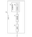
図1は認証システム100が用いられる設備10を示す。認証システム100は設備10を利用する被認証者の認証に用いられる。ここで設備10は建物の出入口に設けられる扉部11である。扉部11は、ドア13と、その側部に設けられる袖部15を含む。ドア13は電気錠装置60の錠前67により施解錠される。認証システム100は、被認証者が正当なユーザである場合、錠前67を施錠又は解錠させる。 FIG. 1 shows an
図2は認証システム100のブロック図である。各ブロックは、ハードウェア的には、コンピュータのCPUやメモリをはじめとする素子や回路で実現でき、ソフトウェア的にはコンピュータプログラム等により実現される。ここでは、それらの連携により実現される機能ブロックを描いている。これらの機能ブロックは、ハードウェア、ソフトウェアの組合せにより様々な態様で実現できる。以降のブロック図も同様である。 FIG. 2 is a block diagram of the
認証システム100は、認証媒体20と、認証装置30と、電気錠装置60を備える。認証装置30と電気錠装置60は、LAN、インターネット等の公知の通信網を介して接続される。 The
認証媒体20はICカードであり、識別情報保持部21と、出力部23を備える。識別情報保持部21は、認証媒体20を一意に識別する鍵IDを識別情報として記憶する。出力部23は、近距離無線通信により認証装置30にデータを送信する。 The
図3は認証装置30のブロック図である。認証装置30は、認証受付装置40と、認証情報保持部31と、認証処理部33と、通信部39を備える。認証受付装置40は、支持パネル41と、第1入力受付部43と、第2入力受付部47と、位置報知ランプ51と、結果報知ランプ53を備える。通信部39は、外部装置、とくに、電気錠装置60とデータ通信を行う。 FIG. 3 is a block diagram of the
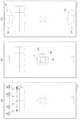
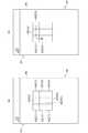
図4(a)、(b)、(c)はそれぞれ支持パネル41の側面断面図、正面図、拡大側面断面図である。支持パネル41は扉部11の袖部15として設置される(図1参照)。支持パネル41は、厚さ方向に対向する前面部111及び後面部113と、前面部111及び後面部113の上下左右の端縁部に沿って設けられる側辺部115とを備え、これらに囲まれた中空構造を有する。前面部111、後面部113は、透光性を有するポリカーボネート製の板材により構成される。前面部111の外面は、扉部11を屋外からみたときに、その扉部11の外観の一部となる露出面41aを形成する。 4A, 4B, and 4C are a side sectional view, a front view, and an enlarged side sectional view of the
前面部111、後面部113の内面には遮光層119が設けられる。遮光層119はブラックフィルムであり、可視光透過率が小さい遮光性材料により構成される。遮光層119は、支持パネル41を外部からみたときに、その内部構造を視認できないように可視光透過率が調整される。遮光層119は遮光性材料の蒸着、塗布等により設けられる。 A
第1入力受付部43は複数の近接センサ44により構成される。各近接センサ44は静電容量型近接センサである。各近接センサ44は支持パネル41の内部に取り付けられる。各近接センサ44は、支持パネル41の上下左右に2行×4列の行列状に配置されるが、その配置態様はこれに限定されない。 The first
各近接センサ44の検知領域45は、支持パネル41の露出面41aの前方に設けられる。この検知領域45に存在する物体の有無が近接センサ44により検知される。各検知領域45により第1入力受付エリア46が形成される。以下、図4(b)の1行目の左端から右端にかけての検知領域45をA1〜A4といい、2行目の左端から右端にかけての検知領域45をB1〜B4という。 The
被認証者が手等の一部を第1入力受付エリア46に進入させて、各検知領域45を任意の順序で移動させると、その移動させた順序で各近接センサ44により物体があると検知される。第1入力受付部43は、各近接センサ44の検知結果から、各検知領域45に物体が進入してから退出するまでの間に、各検知領域45を物体が移動する順序を検出する。たとえば、図5(a)に示すように、検知領域A4に手を進入させて、検知領域A3、A2、A1に移動させてから手を退出させると、第1入力受付部43により検知領域A4、A3、A2、A1の順序が検出される。これにより、被認証者の身体の特定部位、たとえば、手、腕等の動作の軌跡、つまり、被認証者の特定部位のジェスチャーが検出される。第1入力受付部43は、複数の検知領域45に対する物体の接近状況に基づき、被認証者の特定部位のジェスチャーを検出する。 When the person to be authenticated enters a part of the hand or the like into the first
第1入力受付部43は、図3に示すように、被認証者から検出する動作を認証用情報の入力として受け付け、その動作を第1入力情報として認証処理部33に渡す。 As illustrated in FIG. 3, the first
第2入力受付部47は、図4に示すように、リーダー48により構成される。リーダー48は支持パネル41の内部に取り付けられる。リーダー48の読取領域48aは、支持パネル41の露出面41aの前方に設けられる。読取領域48aにより第2入力受付エリア49が形成される。 As shown in FIG. 4, the second
被認証者が認証媒体20を第2入力受付エリア49に進入させると、認証媒体20の識別情報が近距離無線通信により読み取られる。第2入力受付部47は読み取った識別情報を認証用情報の入力として受け付け、これを第2入力情報として認証処理部33に渡す。 When the person to be authenticated causes the
位置報知ランプ51はLED等の複数のランプにより構成され、支持パネル41の内部に設置される。位置報知ランプ51は、点灯時に遮光層119を透過して、露出面41aでの発光範囲を視認できるように光量が調整される。図5(b)ではその発光範囲S1を一点鎖線で示す。位置報知ランプ51は、第2入力受付エリア49に対応した位置に配置され、その位置を被認証者に報知する。位置報知ランプ51の点灯は、認証処理部33から送られる制御信号により制御される。 The
結果報知ランプ53は、発光色の異なるLED等の複数のランプにより構成され、支持パネル41の内部に設置される。結果報知ランプ51は、点灯時に遮光層119を透過して、露出面41aでの発光範囲を視認できるように光量が調整される。図5(c)ではその発光範囲S2を一点鎖線で示す。結果報知ランプ53は、露出面41aの一部を異なる色で発光させ、認証結果を被認証者に報知する。結果報知ランプ53の点灯は、認証処理部33から送られる制御信号により制御される。 The
以上の認証受付装置40では、各入力受付エリア46、49は、各入力受付部43、47を構成する機械装置である近接センサ44やリーダー48が扉部11の外観に露出していない。また、これらの位置を直接的に特定するマーク等の表示が扉部11の外観に表れていない。これにより、各エリア46、49は、これらに入力操作するときの操作位置から、扉部11の外観からは被認証者が視認できない。 In the
認証情報保持部31は、図3に示すように、第1入力受付部43に入力されるべき被認証者のジェスチャーを第1登録情報として予め登録している。認証情報保持部31は、この第1登録情報として、電気錠装置60を施錠するための施錠用ジェスチャーと、解錠するための解錠用ジェスチャーとを登録している。解錠用ジェスチャーは、たとえば、検知領域A4、A3、A2、A1の順序として記憶される。また、施錠用ジェスチャーは、たとえば、検知領域A1、A2、A3、A4の順序として記憶される。また、認証情報保持部31は、第2入力受付部47に入力されるべき識別情報としての鍵IDを第2登録情報として予め登録している。 As illustrated in FIG. 3, the authentication
認証処理部33は、第1入力情報取得部35と、第2入力情報取得部36と、認証部37を含む。第1入力情報取得部35は、第1入力受付部43に入力される第1入力情報を取得する。第2入力情報取得部36は、第2入力受付部47に入力される第2入力情報を取得する。 The
認証部37は、第1入力受付部43に入力された第1入力情報と、認証情報保持部31に登録されている第1登録情報とを照合する。認証部37は、第1入力情報として入力されたジェスチャーと、第1登録情報として登録されているジェスチャーとが一致するか否かを判定するにより照合する。また、認証部37は、第2入力受付部47に入力された第2入力情報と、認証情報保持部31に登録されている第2登録情報とを照合する。認証部37は、第2入力情報として入力された識別情報としての鍵IDと、第2登録情報として登録されている識別情報としての鍵IDとが一致するか否かを判定することにより照合する。 The
図6は電気錠装置60のブロック図である。電気錠装置60は、通信部61と、施解錠制御部63と、施解錠機構65と、状態監視部69を備える。通信部61は、認証装置30と施解錠制御部63のデータ通信を行う。 FIG. 6 is a block diagram of the
施解錠制御部63は、電気錠装置60の各部を統括的に制御する。施解錠制御部63は、認証装置30から施解錠要求信号を取得したとき、それに応じた駆動制御信号を施解錠機構65に出力する。 The locking / unlocking
施解錠機構65は、モータやソレノイド等の駆動源66と、錠前67とを含む。施解錠機構65は、施解錠制御部63からの駆動制御信号により、錠前67を施錠又は解錠させるように駆動源66を駆動させる。駆動源66の駆動により、扉枠のストライクにデッドボルトが進入又は退出等して錠前67が施解錠される。 The locking / unlocking
状態監視部69は、マイクロスイッチやリードスイッチ等の検知センサにより構成される。状態監視部69は、錠前67のデッドボルトの進退状態等を検知して、現在の錠前67の施解錠状態を監視する。状態監視部69は、この状態を示す監視情報を施解錠制御部63に出力する。 The
以上の認証システム100の動作について、電気錠装置60の解錠時と施錠時に分けて説明する。 The operation of the
(電気錠装置60の解錠時の動作)
図7は電気錠装置60の解錠時の処理を示す。認証処理部33は錠前67が施錠された状態にあるとき、以下の処理を実行する。錠前67の施解錠状態は電気錠装置60から受信する監視信号から判断される。(Operation when unlocking electric lock device 60)
FIG. 7 shows a process when the
電気錠装置60は、一次認証手段として被認証者のジェスチャー、二次認証手段として識別情報を保持する認証媒体20を用いて被認証者を認証する。このとき、第1入力受付エリア46は扉部11の外観からは視認できない。よって、第1入力受付エリア46を予め知る被認証者でなければ第1入力受付エリア46に解錠用ジェスチャーを入力し難くなる。なお、位置報知ランプ51の機能はOff状態にされており、第2入力受付エリア49も視認できない。 The
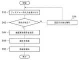
認証処理部33は、第1入力受付部43、第2入力受付部47のそれぞれの機能をOn状態、Off状態にし、第1入力受付部43によりジェスチャーの入力を受け付ける(S10)。被認証者は第1入力受付部43に解錠用ジェスチャーを入力する。詳細には、第1入力受付エリア46の検知領域A4に被認証者が手を進入させて、検知領域A3、A2、A1の順序で移動させ、検知領域A1から手を退出させる。第1入力受付部43は、検知領域A4、A3、A2、A1の移動順序をジェスチャーとして検出し、これを第1入力情報として認証処理部33に渡す。 The
認証処理部33の認証部37は、第1入力受付部43から渡された第1入力情報と第1登録情報を照合する(S12)。照合が失敗した場合(S12のN)、認証処理部33は、結果報知ランプ53によりその旨を報知する(S14)。結果報知ランプ53は、特定の色、たとえば、黄色のランプが点灯してこれを報知する。このとき、第2入力受付部47や位置報知ランプ51は起動させずにOff状態のままにする。被認証者は第2入力受付エリア49の位置を特定できないまま、第1入力受付部43に解錠用ジェスチャーを入力し直す。 The
一方、照合が成立した場合(S12のY)、認証処理部33は、第2入力受付部47による入力の受け付けを開始させる(S16)。この受け付けは第2入力受付部47を起動させて開始してもよい。また、この入力の受け付けは、受け付け期間だけ入力情報を認証処理部33に渡し、他の期間では渡さずに行われてもよい。第2入力受付部47は所定の時間、たとえば、10秒入力を受け付け、その時間の経過後に受け付けを停止する。認証処理部33は、位置報知ランプ51の点灯により、第2入力受付エリア49の位置を被認証者に認識させる(S18)。これは、第2入力受付部47の受け付けの開始後から終了までのいずれかのタイミングで行えばよい。 On the other hand, when the verification is established (Y in S12), the
被認証者は第2入力受付部47に識別情報を認証用情報として入力する。入力は第2入力受付エリア49に認証媒体20を近づけて行われる。第2入力受付部47は、認証媒体20の識別情報を読み取り、これを第2入力情報として認証処理部33に渡す。 The person to be authenticated inputs identification information as authentication information to the second
認証処理部33の認証部37は、第2入力受付部47から渡された第2入力情報と第2登録情報とを照合する(S22)。照合が失敗した場合(S22のN)、認証処理部33は、結果報知ランプ53によりその旨を報知する(S14)。また、認証処理部33は、第2入力受付部47の受け付けを停止させ、位置報知ランプ51の点灯を停止して、第2入力受付エリア49を被認証者に視認できないようにする。被認証者は、一回目の照合をし直す。 The
一方、照合が成立した場合(S22のY)、認証処理部33は、被認証者の認証が成立したと判断し、電気錠装置60に解錠要求信号を送信する(S26)。電気錠装置60の施解錠制御部63は、施解錠機構65の錠前67を解錠させる(S28)。施解錠制御部63は、状態監視部69から出力される錠前67の解錠状態を示す監視情報を取得し、その監視情報を認証装置30に送信する。認証装置30の認証処理部33は、その監視情報を取得したら、結果報知ランプ53により認証が成立して錠前が解錠した旨を報知する(S30)。結果報知ランプ53は、特定の色、たとえば、青色のランプが点灯してこれを報知する。 On the other hand, when the verification is established (Y in S22), the
(電気錠装置60の施錠時の動作)
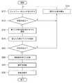
図8は電気錠装置60を施錠時の処理を示す。上述のように、解錠はジェスチャーと認証媒体20を用いて被認証者を認証した。一方、施錠はセキュリティを高める行為であり、正当なユーザしかする必要がないと考えられるため、ここではジェスチャーのみを用いる。(Operation when locking the electric lock device 60)
FIG. 8 shows processing when the
まず、第1入力受付部43、第2入力受付部47のそれぞれの機能をOn状態、Off状態にし、第1入力受付部43によりジェスチャーの入力を受け付ける(S10)。このときも第1入力受付エリア46は視認できない。被認証者は第1入力受付部43に施錠用ジェスチャーを入力する。詳細には、第1入力受付エリア46の検知領域A1に手を進入させて、検知領域A2、A3、A4の順序で移動させ、検知領域A4から退出させる。第1入力受付部43は、検知領域A1、A2、A3、A4の移動順序をジェスチャーとして検出し、これを第1入力情報として認証処理部33に渡す。 First, the functions of the first
認証処理部33の認証部37は、第1入力受付部43から渡された第1入力情報と第1登録情報とを照合する(S42)。照合が失敗した場合(S42のN)、認証処理部33は、結果報知ランプ53によりその旨を報知する(S14)。被認証者は第1入力受付部43に入力し直す。 The
一方、照合が成立した場合(S42のY)、認証処理部33は、被認証者の認証が成立したと判断し、電気錠装置60に施錠要求信号を送信する(S46)。電気錠装置60の施解錠制御部63は、施解錠機構65の錠前67を施錠させる(S48)。施解錠制御部63は、状態監視部69から出力される錠前67の施錠状態を示す監視情報を取得し、その監視情報を認証装置30に送信する。認証装置30の認証処理部33は、その監視情報を取得したら、結果報知ランプ53により錠前67を施錠した旨を報知する(S50)。結果報知ランプ53は、解錠時とは異なる色、たとえば、赤色のランプが点灯してこれを報知する。結果報知ランプ53は、電気錠装置60の施解錠状態に応じて、認証結果を異なる色で被認証者に報知する。 On the other hand, when the verification is established (Y in S42), the
以上の認証システム100によれば、第1入力受付エリア46や第2入力受付エリア49を視認できず、これに第三者が入力操作し難くなる。また、第1入力受付エリア46や第2入力受付エリア49の位置を知っていても、認証手段となる特定の動作を知り、第2入力受付部47に入力する特定の認証用情報の記録された認証媒体20もなければ認証が成立しない。よって、セキュリティが向上する。 According to the
また、各入力受付部43、47の入力受付エリア46、49が設備10の外観に露出せず、設備10のデザイン性が良好となる。また、第1入力受付部43は被認証者のジェスチャーを検出するため、手をかざすのみでは検出されず、誤検知を防止できる。また、認証用情報が動作であるため、指紋等の生体情報の個人情報を予め取得する必要がなく、それらが漏洩する心配もない。 In addition, the
また、第1入力情報を用いた照合が成立したとき、第2入力受付部47が入力の受け付けを開始する。よって、認証の成立に第1入力情報、第2入力情報の入力順序も必要となるため、セキュリティが更に向上する。 When collation using the first input information is established, the second
また、第1入力情報を用いた照合が成立すれば、第2入力受付エリア49の位置を位置報知ランプ51の報知により認識できる。よって、その位置を被認証者が忘れても第2入力受付部47に入力でき、ユーザにとって利便性が高まる。また、第2入力受付エリア49の位置を位置報知ランプ51の点灯により報知するため、夜間においても視認し易くなる。 Further, if the collation using the first input information is established, the position of the second
また、電気錠装置60の施錠時は、被認証者の動作のみを用いて被認証者を認証するため、施錠に必要な手順が減り、操作性が良好となる。 Further, when the
(第2の実施の形態)
図9は第2実施形態に係る認証装置30のブロック図である。第2実施形態では第1入力受付部43が撮像装置70により構成される。以下、第1実施形態で説明した要素と同一の要素に同一の符号を付し、重複する説明を省略する。(Second Embodiment)
FIG. 9 is a block diagram of the
撮像装置70は、カメラ71と、画像解析部73を含む。カメラ71は赤外線カメラである。カメラ71は、撮像により取得した動画像を画像解析部73に出力する。 The
図10(a)、(b)はそれぞれ支持パネル41の側面図、正面図である。カメラ71は支持パネル41の上部の後面41bに取り付けられる。支持パネル41の前面部111の上部には小径の穴41cが形成され、カメラ71は穴41cを通して扉部11の屋外空間の一部を撮像できる。この穴41cは屋外空間から視認したときに目立たない大きさ、たとえば、数mm以下に形成される。カメラ71の撮像範囲72は、支持パネル41の露出面41aの前方に設けられ、この撮像範囲72により第1入力受付エリア46が形成される。 10A and 10B are a side view and a front view of the
画像解析部73は、図9に示すように、カメラ71から出力された動画像の解析により被認証者の特定部位のジェスチャーを検出する。このジェスチャーの例としては、左手を上下、または丸を描くように振る動作、目を特定の順序で開閉する動作等がある。画像解析部73の解析方法は、特に限定されず、公知の方法を用いてよい。 As shown in FIG. 9, the
画像解析部73は検出した被認証者のジェスチャーを第1入力情報として認証処理部33に渡す。認証処理部33は、第1実施形態と同様の処理を行い、撮像装置70に渡された第1入力情報を用いて認証する。 The
以上の認証受付装置40でも、第1実施形態と同様に、第1入力受付エリア46は、第1入力受付部43を構成する撮像装置70が扉部11の外観に露出しておらず、扉部11の外観からは被認証者が視認できない。 Also in the above
以上の認証システム100は、第1実施形態に係る認証システム100と同様の作用効果を得られる。また、カメラ71として赤外線カメラを用いるため、夜間の光源がない環境下でも被認証者の動作を検出できる。なお、カメラ71は可視光カメラでもよい。 The
(第3の実施の形態)
図11は第3実施形態に係る認証システム100のブロック図である。第3実施形態では認証を受けようとする被認証者として複数のユーザA、B、Cがいる。(Third embodiment)
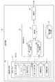
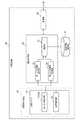
FIG. 11 is a block diagram of an
認証システム100は、複数の認証媒体20と、認証装置30と、電気錠装置60と、管理サーバ80を備える。認証装置30と管理サーバ80は、公知の通信網を介して接続される。 The
各認証媒体20の識別情報保持部21は別々の鍵IDを識別情報として記憶する。ユーザA、B、Cは、それぞれ識別情報保持部21に鍵ID−A〜Cが記憶された認証媒体20を所持する。 The identification
認証装置30は、第1実施形態と機能ブロックが同様なため、図3で説明する。認証情報保持部31は、複数のジェスチャーA、B、Cを第1登録情報として予め登録している。また、認証情報保持部31は、複数の鍵ID−A〜Cを第2登録情報として予め登録している。登録ジェスチャーA、B、Cのそれぞれと、登録鍵ID−A、B、Cのそれぞれは、ユーザA、B、Cと対応づけて記憶される。 The
認証処理部33は、認証が成立したとき、被認証者となるユーザを示す情報と、施設からの入退出を示す入退出信号とを管理サーバ80に通知する。 When authentication is established, the
図12は管理サーバ80のブロック図である。管理サーバ80は、施設内にユーザがいるか否かを管理する。管理サーバ80は、通信部81と、存否情報保持部83と、管理処理部87を備える。通信部81は、認証装置30と管理処理部87の間でデータ通信を行う。 FIG. 12 is a block diagram of the
存否情報保持部83は存否確認テーブル85を記憶する。存否確認テーブル85には、ユーザを特定するユーザ情報と、ユーザが施設内にいるか否かを示すユーザ存否情報とが対応づけて記憶される。 The presence / absence
管理処理部87は、認証装置30から更新要求信号を取得したら、存否確認テーブル85を更新する。また、管理処理部87は、携帯端末等の外部端末から特定のユーザの存否確認要求があると、存否確認テーブル85を参照して、そのユーザの存否を外部端末に通知する。 When the
(電気錠装置60の解錠時の動作)
図13は電気錠装置60の解錠時の処理を示す。被認証者としてユーザAが認証を要求する場合を例にする。(Operation when unlocking electric lock device 60)
FIG. 13 shows a process when the
第1実施形態の処理との相違点のみ説明する。S10〜S22では、第1実施形態の処理とS12とS22が相違する。S12において、認証部37は、第1入力受付部43にユーザAが入力した第1入力情報と、複数の第1登録情報とを照合する。この照合では、第1入力情報としてユーザAが入力したジェスチャーと、第1登録情報としての解錠用の登録ジェスチャーA、B、Cのいずれかが一致するか否かを判定する。 Only differences from the processing of the first embodiment will be described. In S10 to S22, the process of the first embodiment is different from S12 and S22. In S <b> 12, the
また、S22において、認証部37は、第2入力受付部47にユーザAが入力した第2入力情報と、複数の第2登録情報とを照合する。この照合では、第2入力情報としてユーザAが入力した鍵IDと、第2登録情報としての登録鍵ID−A〜Cのいずれかが一致するか否かを判定する。 In S <b> 22, the
照合が成立した場合(S22のY)、認証処理部33は、一回目の照合の成立に用いた登録ジェスチャーに対応するユーザと、二回目の照合の成立に用いた登録鍵IDに対応するユーザとが一致するか否かを判定する(S25)。これらが一致する場合、認証が成立したと判定する。一方、これらが不一致の場合、認証が失敗したと判定する。 When the verification is established (Y in S22), the
たとえば、一回目の照合の成立に登録ジェスチャーAが用いられ、二回目の照合の成立に登録鍵ID−Aが用いられた場合、これらに対応付けられるユーザがユーザAで一致するため、認証が成立したと判定する。一方、一回目の照合の成立に登録ジェスチャーAが用いられ、二回目の照合の成立に登録鍵ID−Bが用いられた場合、これらに対応付けられるユーザがユーザAとユーザBとで不一致のため、認証が失敗したと判定する。 For example, when the registration gesture A is used to establish the first collation and the registration key ID-A is used to establish the second collation, the user associated with these matches with the user A, so authentication is performed. It is determined that it has been established. On the other hand, when the registration gesture A is used for the establishment of the first verification and the registration key ID-B is used for the establishment of the second verification, the users associated with these do not match between the user A and the user B. Therefore, it is determined that the authentication has failed.
認証が失敗した場合(S25のN)、認証処理部33は、結果報知ランプ53によりその旨を報知する(S14)。一方、認証が成立した場合(S25のY)、第1実施形態と同様にS26、S28、S30を行う。また、認証が成立した場合(S25のY)、認証処理部33は、照合の成立に用いた登録ジェスチャーに対応するユーザAを示す情報と、ユーザAが施設に入ってきたことを示す信号と、更新要求信号を管理サーバ80に送信する。管理サーバ80の管理処理部87は、これら情報を取得したら、「ユーザAは施設内にいる」として、存否確認テーブル85のユーザ存否情報を更新する(S34)。 When authentication fails (N of S25), the
(電気錠装置60の施錠時の動作)
図14は電気錠装置60の施錠時の処理を示す。S10、S42〜S50では第1実施形態の処理とS42が相違する。S42において、認証処理部33は、第1入力受付部43にユーザAが入力した第1入力情報と、複数の第1登録情報とを照合する。この照合の成立条件は解錠時と同様である。(Operation when locking the electric lock device 60)
FIG. 14 shows a process when the
照合が成立した場合(S42のY)、認証処理部33は、照合の成立に用いた登録ジェスチャーに対応するユーザAを示す情報と、ユーザAが施設内から退出したことを示す信号と、更新要求信号を管理サーバ80に送信する。管理サーバ80の管理処理部87は、これら情報を取得したら、「ユーザAは施設内にいない」として、存否確認テーブル85のユーザ存否情報を更新する(S54)。 When the collation is established (Y in S42), the
以上の認証システム100でも、第1実施形態に係る認証システム100と同様の作用効果が得られる。また、被認証者の動作からユーザを特定でき、その特定したユーザの施設内での存否を管理サーバ80により管理できる。よって、施設から離れた場所からでも、外部端末を用いて施設内のユーザの存否を確認できる。たとえば、共働きの両親と小学生の子供がいる家族構成の場合、親の仕事中には子供の学校からの帰宅状況を確認し難く心配になる。この家族の住居内での存否を管理サーバ80により管理できれば、職場からでも親が子供の帰宅状況を確認でき、安心して仕事できるメリットがある。 Even with the above-described
また、認証手段となる動作と、識別情報となる鍵IDのそれぞれがユーザと対応づけて記憶されており、その両者に対応するユーザが同じときにはじめて認証が成立する。よって、ユーザBの登録ジェスチャーBを知っている第三者がユーザAの鍵ID−Aを保持する認証媒体を所持していても認証が成立せず、セキュリティが更に向上する。 Further, each of the operation as the authentication means and the key ID as the identification information is stored in association with the user, and authentication is established only when the users corresponding to both are the same. Therefore, even if a third party who knows the registration gesture B of the user B has an authentication medium that holds the key ID-A of the user A, authentication is not established, and security is further improved.
(第4の実施の形態)
図15は第4実施形態に係る認証システム100のブロック図である。第1実施形態では第1入力受付部43が設備10側に付帯する形で設置される例を説明した。第4実施形態では第1入力受付部43が認証媒体20に設置される。(Fourth embodiment)
FIG. 15 is a block diagram of the
認証媒体20はスマートフォン、タブレットPC等の携帯端末25である。認証媒体20は、識別情報保持部21と、出力部23の他に、第1入力受付部43を備える。第1入力受付部43は携帯端末25が備えるタッチパネル27により構成される。タッチパネル27の接触面により第1入力受付エリア46(図示せず)が形成される。 The
第1入力受付部43に認証用情報を入力するとき、携帯端末25の制御部は専用アプリケーションソフト、ブラウザ等を起動して、タッチパネル27に認証用画面を表示させて、認証用情報の入力を受け付ける。 When the authentication information is input to the first
図16は認証用画面90を示す。認証用画面90は複数の検知領域45を含む。同図で1、2、3行目の左端から右端にかけての検知領域45をそれぞれC1〜C3、D1〜D3、E1〜E3という。 FIG. 16 shows an
第1入力受付部43は、タッチパネル27の検知結果から、各検知領域45を物体が移動する順序を検出する。たとえば、図16(b)に示すように、検知領域C3に指を接触させて、領域C2、C1、D1に移動させてから指を離すと、第1入力受付部43により領域C3、C2、C1、D1の順序が検出される。これにより、被認証者の指のジェスチャーが検出される。第1入力受付部43は、検出した被認証者のジェスチャーを第1入力情報として生成する。 The first
図17は認証装置30の構成を示すブロック図である。認証装置30は、第1実施形態のように第1入力受付部43や位置報知ランプ51を備えていない。 FIG. 17 is a block diagram showing the configuration of the
被認証者が第2入力受付部47の第2入力受付エリア49に携帯端末25を進入させると、認証媒体20の識別情報と、第1入力情報としてのジェスチャーが近距離無線通信により読み取られる。 When the person to be authenticated causes the
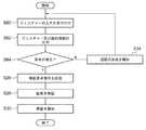
(電気錠装置60の解錠時の動作)
第1実施形態では第1入力情報を用いた照合の成立後、第2入力情報を用いて照合した。本実施形態では各入力情報を用いた照合を同じタイミングで行う。(Operation when unlocking electric lock device 60)
In the first embodiment, after the verification using the first input information is established, the verification is performed using the second input information. In this embodiment, collation using each input information is performed at the same timing.
図18は電気錠装置60の解錠時の処理を示す。被認証者は携帯端末25を操作してアプリケーションソフトを起動し、タッチパネル27に認証用画面90を表示させ、タッチパネル27によりジェスチャーの入力を受け付ける(S60)。被認証者はタッチパネル27に解錠用ジェスチャーを入力する。第1入力受付部43は被認証者のジェスチャーを検出し、これを第1入力情報として生成する。 FIG. 18 shows a process when the
携帯端末25は第2入力受付部47に識別情報と、第1入力情報としてのジェスチャーを出力する(S62)。第2入力受付部47への出力は第2入力受付エリア49に携帯端末25を近づけて行われる。第2入力受付部47は携帯端末25から受信した第1入力情報を認証処理部33の第1入力情報取得部35に渡し、識別情報を第2入力情報として認証処理部33の第2入力情報取得部36に渡す。 The
認証処理部33の認証部37は、第2入力受付部47から渡された第1入力情報と第1登録情報を照合するとともに、第2入力受付部47から渡された第2入力情報と第2登録情報とを照合する(S64)。この照合の成立条件は第1実施形態と同様である。 The
いずれかの照合が失敗した場合(S64のN)、認証処理部33は、結果報知ランプ53によりその旨を報知する(S14)。一方、両方の照合が成立した場合(S64のY)、認証処理部33は、被認証者の認証が成立したと判断し、電気錠装置60に解錠要求信号を送信する(S26)。この後は第1実施形態と同様である。電気錠装置60を施錠させるときも同様の処理となるので説明を省略する。 If any of the verifications fails (N in S64), the
以上の認証システム100によれば、第1入力受付エリア46を設備10の外観において視認できず、携帯端末25を所持していないと認証用情報を入力できない。また、第2入力受付エリア49も視認できないため、これに第三者が入力操作し難くなる。また、第三者が携帯端末25を所持し、第2入力受付エリア49の位置を知っていても、認証手段となる特定の動作を知らなければ認証が成立しない。よって、セキュリティが向上する。 According to the
以上、実施の形態に基づき本発明を説明したが、実施の形態は、本発明の原理、応用を示すにすぎない。また、実施の形態には、請求の範囲に規定された本発明の思想を逸脱しない範囲において、多くの変形例や配置の変更が可能である。 As mentioned above, although this invention was demonstrated based on embodiment, embodiment only shows the principle and application of this invention. In the embodiment, many modifications and arrangements can be made without departing from the spirit of the present invention defined in the claims.
認証システム100が用いられる設備10として建物の扉部11を説明した。設備10は、これに限らず、たとえば、発電用設備、動力設備等の電気設備や、機械警備装置等の防犯設備でもよい。いずれの設備10に用いられる場合も、認証システム100は、認証が成立したとき、その設備10の利用ができるように機械装置を制御する。たとえば、電気設備に用いられる場合、認証が成立したとき、その電気設備の電源をOnにする。また、防犯設備に用いられる場合、認証が成立したとき、防犯設備の入力操作の受け付けを開始する。 The
認証媒体20はICカードや携帯電話に限定されず、リモートコントロール等により構成されてもよい。また、認証媒体20が保持する識別情報はユーザを識別できればよく、鍵IDの他、ユーザの住所、電話番号、携帯端末のMACアドレス等のユーザに固有の情報でもよい。 The
第1実施形態に係る支持パネル41は第1入力受付部43や第2入力受付部47が取り付けられ、これらを支持する支持体として説明した。支持体は、パネルに限定されず、ブロック等の種々の形状に形成されてもよい。また、この支持体は、第1実施形態に係る扉部11のドア13や周囲の外壁により構成されてもよい。この場合、第1入力受付部43や第2入力受付部47等の各部品はドア13や外壁に内蔵されてもよい。 The
また、支持パネル41の前面部111、後面部113は、透光性を有する素材の板材であればよく、ポリカーボネートの他、アクリル、ガラス等を素材としてもよい。また、支持パネル41は中空構造でなくともよく、後面部113、側辺部115を省略した構造でもよい。また、支持パネル41の前面部111、後面部113は、木材、樹脂材、鋼材等の透光性のない素材により構成されてもよい。 Moreover, the
第2入力受付部47は近距離無線通信により認証媒体20の識別情報を読み取る無線モジュールとしてのリーダー48により構成されたが、その無線方式はこれに限らない。また、第2入力受付部47は、この他にも、起動しているときだけ支持パネル41の露出面41aにテンキー部が表示されるタッチパネル等により構成されてもよい。また、第2入力受付エリア49は視認できる態様で設けられていてもよい。この場合、第2入力受付部47は指紋センサー、テンキーユニット等の公知の入力受付装置でもよい。 The second
位置報知ランプ51は第2入力受付エリア49の位置を報知する位置報知部として説明した。また、結果報知ランプ53は認証結果を被認証者に報知する結果報知部として説明した。これらは、ランプ以外にも、音声の出力により位置や結果を報知するスピーカ等により構成されてもよい。 The
第1実施形態では一回目の照合が失敗した場合(S12のN)、結果報知ランプ53によりこの旨を報知したが、この報知はなくともよい。一回目の照合が成立しないかぎり、第2入力受付部47の位置が報知されず、この存在を第三者が気づき難くなり、セキュリティが向上する。 In the first embodiment, when the first verification fails (N in S12), the
第1実施形態では、第1入力情報を用いた照合が成立したとき、第2入力受付部47が入力の受け付けを開始した。この代わりに、第2入力受付部47が先に入力の受け付けを開始し、第2入力受付部47に入力された入力情報を用いた照合が成立したとき、第1入力受付部43が入力の受け付けを開始してもよい。この場合、第1入力受付部43が入力の受け付けを開始してから、第1入力受付エリア46の位置を報知する位置報知部を備えていてもよい。この場合でも、錠前67が解錠された状態にあるとき、第2入力受付部47ではなく第1入力受付部43の入力のみ受け付け、ジェスチャーのみを用いて認証してもよい。 In the first embodiment, when collation using the first input information is established, the second
第4実施形態では、携帯端末25に第1入力受付部43となるタッチパネル27が設置された。変形例として、第1入力受付部43が設置される携帯端末25とは別体の認証媒体を用い、その認証媒体にのみ識別情報を保持させてもよい。この場合、第1実施形態と同様に、携帯端末25の第1入力受付部43に入力したジェスチャーを用いて照合したうえで、認証媒体20を用いて第2入力受付部47に入力した識別情報を用いて照合してもよい。この場合、第三者に携帯端末25を盗まれても、別体の認証媒体がないかぎり認証が成立せず、セキュリティが向上する。 In the fourth embodiment, the
第4実施形態では携帯端末25に設置される第1入力受付部43がタッチパネル27であったが、第1入力受付部43は加速度センサ、ジャイロセンサ等により構成されてもよい。ジャイロセンサ等により構成される場合、第1入力受付部43は、認証媒体20の移動軌跡を検知することにより、被認証者のジェスチャーを検出する。 In 4th Embodiment, although the 1st
また、各実施形態の構成要素は組み合わせられてもよい。たとえば、第1実施形態のように支持パネル41に第1入力受付部43を設けたうえで、第4実施形態のように携帯端末25にも第1入力受付部43を設けてもよい。この場合、支持パネル41の第1入力受付部43と、携帯端末25の第1入力受付部43とのいずれに入力された入力情報を用いて照合してもよい。 Moreover, the component of each embodiment may be combined. For example, after providing the 1st
10・・・設備、25・・・携帯端末、33・・・認証処理部、40・・・認証受付装置、41a・・・露出面、43・・・入力受付部、43・・・第1入力受付部、46・・・第1入力受付エリア、47・・・第2入力受付部、49・・・入力受付エリア、60・・・電気錠装置、67・・・錠前、80・・・管理サーバ、100・・・認証システム。DESCRIPTION OF
Claims (9)
Translated fromJapanese被認証者から検出する動作を認証用情報の入力として受け付ける第1入力受付部と、
前記第1入力受付部が受け付ける認証用情報とは別の認証用情報の入力を受け付ける第2入力受付部と、
前記第1入力受付部に入力される第1入力情報と、予め登録される第1登録情報とを照合するとともに、前記第2入力受付部に入力される第2入力情報と、予め登録される第2登録情報とを照合することにより、被認証者を認証する認証処理部と、を備え、
前記第1入力受付部の入力受付エリアは、前記設備の外観において視認できない態様で設けられ、
前記第1入力受付部又は前記第2入力受付部の一方は、入力の受け付けを先に開始し、
前記認証処理部は、前記第1入力受付部と前記第2入力受付部のうち先に受け付けを開始したものから入力される入力情報と登録情報を照合し、
前記第1入力受付部と前記第2入力受付部のうちの一方から入力される入力情報を用いた照合が成立したとき、他方の入力の受け付けを開始し、
前記第1入力受付部と前記第2入力受付部のうちの他方の入力受付エリアは、前記設備の外観において視認できない態様で設けられ、
前記第1入力受付部と前記第2入力受付部のうちの他方が入力の受け付けを開始してからの何れかのタイミングにおいて、その入力受付エリアの位置を報知する位置報知部を更に備えることを特徴とする認証システム。An authentication system for authenticating a person to be authenticated who uses equipment,
A first input receiving unit that receives an operation detected from the person to be authenticated as an input of authentication information;
A second input receiving unit for receiving an input of authentication information different from the authentication information received by the first input receiving unit;
The first input information input to the first input receiving unit and the first registration information registered in advance are collated, and the second input information input to the second input receiving unit is registered in advance. An authentication processing unit that authenticates the person to be authenticated by collating with the second registration information,
The input reception area of the first input reception unit is provided inan aspect that cannot be visually recognized in the appearance of the equipment,
One of the first input receiving unit or the second input receiving unit starts receiving input first,
The authentication processing unit collates input information and registration information input from the first input receiving unit and the second input receiving unit that started receiving earlier,
When collation using input information input from one of the first input reception unit and the second input reception unit is established, reception of the other input is started,
The other input reception area of the first input reception unit and the second input reception unit is provided in an aspect that cannot be visually recognized in the appearance of the facility,
A position notifying unit for notifying the position of the input receiving area at any timing after the other of the first input receiving unit and the second input receiving unit starts receiving an input. authentication systemwhich is characterized.
前記認証処理部による認証が成立したときに、前記電気錠装置が前記錠前を施解錠させることを特徴とする請求項1に記載の認証システム。An electric lock device for electrically locking and unlocking the lock;
When authentication by the authentication processing unit is established, the authentication system accordingto claim1, wherein the electric lock device is characterized in that for locking and unlocking the lock.
前記認証処理部による認証が成立したとき、前記第1入力情報との照合が成立した第1登録情報に対応するユーザを示す情報を、ユーザが施設内にいるか否かを示す情報を管理する管理サーバに送信することを特徴とする請求項1から3のいずれかに記載の認証システム。The authentication processing unit collates the first input information with a plurality of first registration information each associated with any one of a plurality of users,
Management for managing information indicating whether or not the user is in the facility, information indicating the user corresponding to the first registered information that has been verified with the first input information when authentication by the authentication processing unit is established authentication system according to any one of claims 1 to3, characterized in that to the server.
前記認証処理部は、前記第1入力情報との照合が成立した第1登録情報に対応するユーザと、前記第2入力情報との照合が成立した第2登録情報に対応するユーザとが一致するか否かを判定することにより、被認証者を認証することを特徴とする請求項1から4のいずれかに記載の認証システム。The authentication processing unit collates the first input information with a plurality of first registration information each associated with any of a plurality of users, and the second input information with any of the plurality of users. A plurality of pieces of second registration information associated with
The authentication processing unit matches a user corresponding to the first registration information that has been verified with the first input information and a user corresponding to the second registration information that has been verified with the second input information. The authentication system according to any one of claims 1 to4 , wherein the person to be authenticated is authenticated by determining whether or not.
支持体と、
前記支持体に取り付けられ、被認証者の動作を検出することにより認証用情報の入力を受け付ける第1入力受付部と、
前記支持体に取り付けられ、認証用情報の入力を受け付ける第2入力受付部と、を備え、
前記認証処理部は、前記第1入力受付部に入力される第1入力情報と、予め登録される第1登録情報とを照合するとともに、前記第2入力受付部に入力される第2入力情報と、予め登録される第2登録情報とを照合することにより、被認証者を認証し、
前記支持体は、前記設備の外観の一部となる露出面を含み、
前記第1入力受付部の入力受付エリアは、前記露出面の外観において視認できない態様で設けられ、
前記第1入力受付部又は前記第2入力受付部の一方は、入力の受け付けを先に開始し、
前記認証処理部は、前記第1入力受付部と前記第2入力受付部のうち先に受け付けを開始したものから入力される入力情報と登録情報を照合し、
前記第1入力受付部と前記第2入力受付部のうちの一方から入力される入力情報を用いた照合が成立したとき、他方の入力の受け付けを開始し、
前記第1入力受付部と前記第2入力受付部のうちの他方の入力受付エリアは、前記露出面の外観において視認できない態様で設けられ、
前記第1入力受付部と前記第2入力受付部のうちの他方が入力の受け付けを開始してからの何れかのタイミングにおいて、その入力受付エリアの位置を報知する位置報知部を更に備えることを特徴とする認証受付装置。An authentication accepting device used for authenticating a person who uses equipment by an authenticationprocessing unit ,
A support;
A first input receiving unit that is attached to the support and receives an input of authentication information by detecting an operation of the person to be authenticated;
A second input receiving unit that is attached to the support and receives an input of authentication information;
The authentication processing unit collates first input information input to the first input receiving unit with first registration information registered in advance, and second input information input to the second input receiving unit. And the second registration information registered in advance to authenticate the person to be authenticated,
The support includes an exposed surface that becomes a part of the appearance of the facility;
The input reception area of the first input reception unit is provided ina manner that is not visible in the appearance of the exposed surface,
One of the first input receiving unit or the second input receiving unit starts receiving input first,
The authentication processing unit collates input information and registration information input from the first input receiving unit and the second input receiving unit that started receiving earlier,
When collation using input information input from one of the first input reception unit and the second input reception unit is established, reception of the other input is started,
The other input receiving area of the first input receiving unit and the second input receiving unit is provided in an aspect that cannot be visually recognized in the appearance of the exposed surface,
In any timing after the other of the said first input receiving unit second input receiving section starts reception of input, further comprising Rukotoposition notifying section for notifying the position of the input receiving area An authentication acceptance device characterized by the above.
被認証者から検出する動作を認証用情報の入力として第1入力受付部により受け付け、その入力される第1入力情報と、予め登録される第1登録情報とを認証処理部により照合する第1ステップと、
第1ステップで受け付ける認証用情報とは別の認証用情報の入力を第2入力受付部により受け付け、その入力される第2入力情報と、予め登録される第2登録情報とを前記認証処理部により照合する第2ステップと、を含み、
前記第1ステップの照合結果と、前記第2ステップの照合結果とに基づき被認証者を認証し、
前記第1入力受付部の入力受付エリアは、前記設備の外観において視認できない態様で設けられ、
前記第1入力受付部又は前記第2入力受付部の一方は、入力の受け付けを先に開始し、
前記認証処理部は、前記第1入力受付部と前記第2入力受付部のうち先に受け付けを開始したものから入力される入力情報と登録情報を照合し、
前記第1入力受付部と前記第2入力受付部のうちの一方から入力される入力情報を用いた照合が成立したとき、他方の入力の受け付けを開始し、
前記第1入力受付部と前記第2入力受付部のうちの他方の入力受付エリアは、前記設備の外観において視認できない態様で設けられ、
前記第1入力受付部と前記第2入力受付部のうちの他方が入力の受け付けを開始してからの何れかのタイミングにおいて、その入力受付エリアの位置を報知することを特徴とする認証方法。An authentication method for authenticating a person to be authenticatedusing equipment ,
The first input receiving unit receives an operation detected from the person to be authenticated as an input ofauthentication information, and theauthentication processing unit compares the input first input information with the first registered information registered in advance. Steps,
An input of authentication information different from the authentication information received in the first step is receivedby the second input receiving unit , and the input second input information and pre-registered second registration information are received by theauthentication processing unit. A second stepof matching by
Authenticate the person to be authenticated based on the collation result of the first step and the collation result of the second step;
The input reception area of the first input reception unit is provided in an aspect that cannot be visually recognized in the appearance of the equipment,
One of the first input receiving unit or the second input receiving unit starts receiving input first,
The authentication processing unit collates input information and registration information input from the first input receiving unit and the second input receiving unit that started receiving earlier,
When collation using input information input from one of the first input reception unit and the second input reception unit is established, reception of the other input is started,
The other input reception area of the first input reception unit and the second input reception unit is provided in an aspect that cannot be visually recognized in the appearance of the facility,
An authentication method, whereinthe position of the input receiving area is notified at any timing after the other of the first input receiving unit and the second input receiving unit starts receiving an input .
Priority Applications (2)
| Application Number | Priority Date | Filing Date | Title |
|---|---|---|---|
| JP2014027792AJP6150739B2 (en) | 2014-02-17 | 2014-02-17 | Authentication system, authentication reception apparatus, and authentication method |
| PCT/JP2015/050506WO2015122221A1 (en) | 2014-02-17 | 2015-01-09 | Authentication system, authentication acceptance device, and authentication method |
Applications Claiming Priority (1)
| Application Number | Priority Date | Filing Date | Title |
|---|---|---|---|
| JP2014027792AJP6150739B2 (en) | 2014-02-17 | 2014-02-17 | Authentication system, authentication reception apparatus, and authentication method |
Publications (2)
| Publication Number | Publication Date |
|---|---|
| JP2015153254A JP2015153254A (en) | 2015-08-24 |
| JP6150739B2true JP6150739B2 (en) | 2017-06-21 |
Family
ID=53799969
Family Applications (1)
| Application Number | Title | Priority Date | Filing Date |
|---|---|---|---|
| JP2014027792AExpired - Fee RelatedJP6150739B2 (en) | 2014-02-17 | 2014-02-17 | Authentication system, authentication reception apparatus, and authentication method |
Country Status (2)
| Country | Link |
|---|---|
| JP (1) | JP6150739B2 (en) |
| WO (1) | WO2015122221A1 (en) |
Cited By (1)
| Publication number | Priority date | Publication date | Assignee | Title |
|---|---|---|---|---|
| JP2021063365A (en)* | 2019-10-11 | 2021-04-22 | mui Lab株式会社 | Door device and system which have built-in operation display panel |
Families Citing this family (2)
| Publication number | Priority date | Publication date | Assignee | Title |
|---|---|---|---|---|
| JP7341447B2 (en)* | 2017-05-19 | 2023-09-11 | 株式会社 エヌティーアイ | Executing devices, instructing devices, methods executed on them, computer programs |
| JP7629364B2 (en)* | 2021-06-30 | 2025-02-13 | 三菱電機ビルソリューションズ株式会社 | Personal authentication system |
Family Cites Families (6)
| Publication number | Priority date | Publication date | Assignee | Title |
|---|---|---|---|---|
| JPS5899808A (en)* | 1981-12-08 | 1983-06-14 | Horiba Ltd | Noncontacting system controller |
| JP2004068483A (en)* | 2002-08-08 | 2004-03-04 | Misawa Homes Co Ltd | Card key system |
| JP2008027014A (en)* | 2006-07-19 | 2008-02-07 | Dainippon Printing Co Ltd | Room reservation management system |
| JP2010090582A (en)* | 2008-10-07 | 2010-04-22 | Denso Wave Inc | Authentication device |
| JP2011047149A (en)* | 2009-08-26 | 2011-03-10 | Panasonic Electric Works Co Ltd | Access management system, and environmental control system |
| JP5699019B2 (en)* | 2011-04-01 | 2015-04-08 | 株式会社Nttドコモ | Authentication apparatus, authentication method, and program |
- 2014
- 2014-02-17JPJP2014027792Apatent/JP6150739B2/ennot_activeExpired - Fee Related
- 2015
- 2015-01-09WOPCT/JP2015/050506patent/WO2015122221A1/enactiveApplication Filing
Cited By (1)
| Publication number | Priority date | Publication date | Assignee | Title |
|---|---|---|---|---|
| JP2021063365A (en)* | 2019-10-11 | 2021-04-22 | mui Lab株式会社 | Door device and system which have built-in operation display panel |
Also Published As
| Publication number | Publication date |
|---|---|
| JP2015153254A (en) | 2015-08-24 |
| WO2015122221A1 (en) | 2015-08-20 |
Similar Documents
| Publication | Publication Date | Title |
|---|---|---|
| US11282314B2 (en) | Systems and methods for controlling access to physical space | |
| US12205429B2 (en) | Biometric enabled access control | |
| CN106255789A (en) | The use of touch-surface and the electronic lock of abrasion equilibrium is carried out by random code input | |
| US10438463B2 (en) | Access control system and method | |
| JP2007262695A (en) | Entrance management equipment with enhanced security function, and entrance management method | |
| CN114846526B (en) | System and method for logging in a user of a wireless biometric lock | |
| WO2014157770A1 (en) | Method for authenticating entrance and exit by using digital door lock and wireless communication terminal, and apparatus therefor | |
| JP6150739B2 (en) | Authentication system, authentication reception apparatus, and authentication method | |
| JP4606868B2 (en) | Personal authentication device | |
| US7818583B2 (en) | Personal authentication apparatus | |
| US20240416869A1 (en) | Facial recognition entry system with secondary authentication | |
| US9390570B1 (en) | Virtual touch-control lock | |
| KR20090041619A (en) | Access control system | |
| JP4749916B2 (en) | Biological information-based electric lock system | |
| JP5520660B2 (en) | Access control system | |
| JP5411776B2 (en) | Access control system | |
| KR20140089773A (en) | The rotation authentication for the have all digital door lock and the digital door lock of access authentication method | |
| KR20040098725A (en) | Method for opening the door-lock apparatus by authentication keys | |
| JP2006178591A (en) | Authentication device, security device, and authentication method in security device | |
| KR102751142B1 (en) | System and method for controlling entrance of complex authentication method using a smart device | |
| JP2009035866A (en) | Electric locking-unlocking system | |
| WO2025069044A1 (en) | System and method for providing access to a secured area | |
| CN118942177A (en) | Authentication device and access management system | |
| JP2020060089A (en) | Indoor locking device and attaching method of locking system | |
| KR20220156312A (en) | Digital entry logging system using beacon based dynamic authentication information |
Legal Events
| Date | Code | Title | Description |
|---|---|---|---|
| A621 | Written request for application examination | Free format text:JAPANESE INTERMEDIATE CODE: A621 Effective date:20160721 | |
| A131 | Notification of reasons for refusal | Free format text:JAPANESE INTERMEDIATE CODE: A131 Effective date:20170214 | |
| A521 | Written amendment | Free format text:JAPANESE INTERMEDIATE CODE: A523 Effective date:20170413 | |
| TRDD | Decision of grant or rejection written | ||
| A01 | Written decision to grant a patent or to grant a registration (utility model) | Free format text:JAPANESE INTERMEDIATE CODE: A01 Effective date:20170523 | |
| A61 | First payment of annual fees (during grant procedure) | Free format text:JAPANESE INTERMEDIATE CODE: A61 Effective date:20170523 | |
| R150 | Certificate of patent or registration of utility model | Ref document number:6150739 Country of ref document:JP Free format text:JAPANESE INTERMEDIATE CODE: R150 | |
| R250 | Receipt of annual fees | Free format text:JAPANESE INTERMEDIATE CODE: R250 | |
| S111 | Request for change of ownership or part of ownership | Free format text:JAPANESE INTERMEDIATE CODE: R313111 | |
| R350 | Written notification of registration of transfer | Free format text:JAPANESE INTERMEDIATE CODE: R350 | |
| LAPS | Cancellation because of no payment of annual fees |