JP6149841B2 - Hybrid car - Google Patents
Hybrid carDownload PDFInfo
- Publication number
- JP6149841B2 JP6149841B2JP2014215466AJP2014215466AJP6149841B2JP 6149841 B2JP6149841 B2JP 6149841B2JP 2014215466 AJP2014215466 AJP 2014215466AJP 2014215466 AJP2014215466 AJP 2014215466AJP 6149841 B2JP6149841 B2JP 6149841B2
- Authority
- JP
- Japan
- Prior art keywords
- catalyst warm
- control
- catalyst
- battery
- engine
- Prior art date
- Legal status (The legal status is an assumption and is not a legal conclusion. Google has not performed a legal analysis and makes no representation as to the accuracy of the status listed.)
- Active
Links
Images


Classifications
- B—PERFORMING OPERATIONS; TRANSPORTING
- B60—VEHICLES IN GENERAL
- B60W—CONJOINT CONTROL OF VEHICLE SUB-UNITS OF DIFFERENT TYPE OR DIFFERENT FUNCTION; CONTROL SYSTEMS SPECIALLY ADAPTED FOR HYBRID VEHICLES; ROAD VEHICLE DRIVE CONTROL SYSTEMS FOR PURPOSES NOT RELATED TO THE CONTROL OF A PARTICULAR SUB-UNIT
- B60W20/00—Control systems specially adapted for hybrid vehicles
- B60W20/10—Controlling the power contribution of each of the prime movers to meet required power demand
- B60W20/15—Control strategies specially adapted for achieving a particular effect
- B60W20/16—Control strategies specially adapted for achieving a particular effect for reducing engine exhaust emissions
- B—PERFORMING OPERATIONS; TRANSPORTING
- B60—VEHICLES IN GENERAL
- B60K—ARRANGEMENT OR MOUNTING OF PROPULSION UNITS OR OF TRANSMISSIONS IN VEHICLES; ARRANGEMENT OR MOUNTING OF PLURAL DIVERSE PRIME-MOVERS IN VEHICLES; AUXILIARY DRIVES FOR VEHICLES; INSTRUMENTATION OR DASHBOARDS FOR VEHICLES; ARRANGEMENTS IN CONNECTION WITH COOLING, AIR INTAKE, GAS EXHAUST OR FUEL SUPPLY OF PROPULSION UNITS IN VEHICLES
- B60K6/00—Arrangement or mounting of plural diverse prime-movers for mutual or common propulsion, e.g. hybrid propulsion systems comprising electric motors and internal combustion engines
- B60K6/20—Arrangement or mounting of plural diverse prime-movers for mutual or common propulsion, e.g. hybrid propulsion systems comprising electric motors and internal combustion engines the prime-movers consisting of electric motors and internal combustion engines, e.g. HEVs
- B60K6/42—Arrangement or mounting of plural diverse prime-movers for mutual or common propulsion, e.g. hybrid propulsion systems comprising electric motors and internal combustion engines the prime-movers consisting of electric motors and internal combustion engines, e.g. HEVs characterised by the architecture of the hybrid electric vehicle
- B60K6/44—Series-parallel type
- B60K6/445—Differential gearing distribution type
- B—PERFORMING OPERATIONS; TRANSPORTING
- B60—VEHICLES IN GENERAL
- B60W—CONJOINT CONTROL OF VEHICLE SUB-UNITS OF DIFFERENT TYPE OR DIFFERENT FUNCTION; CONTROL SYSTEMS SPECIALLY ADAPTED FOR HYBRID VEHICLES; ROAD VEHICLE DRIVE CONTROL SYSTEMS FOR PURPOSES NOT RELATED TO THE CONTROL OF A PARTICULAR SUB-UNIT
- B60W10/00—Conjoint control of vehicle sub-units of different type or different function
- B60W10/04—Conjoint control of vehicle sub-units of different type or different function including control of propulsion units
- B60W10/06—Conjoint control of vehicle sub-units of different type or different function including control of propulsion units including control of combustion engines
- B—PERFORMING OPERATIONS; TRANSPORTING
- B60—VEHICLES IN GENERAL
- B60W—CONJOINT CONTROL OF VEHICLE SUB-UNITS OF DIFFERENT TYPE OR DIFFERENT FUNCTION; CONTROL SYSTEMS SPECIALLY ADAPTED FOR HYBRID VEHICLES; ROAD VEHICLE DRIVE CONTROL SYSTEMS FOR PURPOSES NOT RELATED TO THE CONTROL OF A PARTICULAR SUB-UNIT
- B60W10/00—Conjoint control of vehicle sub-units of different type or different function
- B60W10/04—Conjoint control of vehicle sub-units of different type or different function including control of propulsion units
- B60W10/08—Conjoint control of vehicle sub-units of different type or different function including control of propulsion units including control of electric propulsion units, e.g. motors or generators
- B—PERFORMING OPERATIONS; TRANSPORTING
- B60—VEHICLES IN GENERAL
- B60W—CONJOINT CONTROL OF VEHICLE SUB-UNITS OF DIFFERENT TYPE OR DIFFERENT FUNCTION; CONTROL SYSTEMS SPECIALLY ADAPTED FOR HYBRID VEHICLES; ROAD VEHICLE DRIVE CONTROL SYSTEMS FOR PURPOSES NOT RELATED TO THE CONTROL OF A PARTICULAR SUB-UNIT
- B60W10/00—Conjoint control of vehicle sub-units of different type or different function
- B60W10/24—Conjoint control of vehicle sub-units of different type or different function including control of energy storage means
- B60W10/26—Conjoint control of vehicle sub-units of different type or different function including control of energy storage means for electrical energy, e.g. batteries or capacitors
- B—PERFORMING OPERATIONS; TRANSPORTING
- B60—VEHICLES IN GENERAL
- B60W—CONJOINT CONTROL OF VEHICLE SUB-UNITS OF DIFFERENT TYPE OR DIFFERENT FUNCTION; CONTROL SYSTEMS SPECIALLY ADAPTED FOR HYBRID VEHICLES; ROAD VEHICLE DRIVE CONTROL SYSTEMS FOR PURPOSES NOT RELATED TO THE CONTROL OF A PARTICULAR SUB-UNIT
- B60W20/00—Control systems specially adapted for hybrid vehicles
- B60W20/40—Controlling the engagement or disengagement of prime movers, e.g. for transition between prime movers
- F—MECHANICAL ENGINEERING; LIGHTING; HEATING; WEAPONS; BLASTING
- F01—MACHINES OR ENGINES IN GENERAL; ENGINE PLANTS IN GENERAL; STEAM ENGINES
- F01N—GAS-FLOW SILENCERS OR EXHAUST APPARATUS FOR MACHINES OR ENGINES IN GENERAL; GAS-FLOW SILENCERS OR EXHAUST APPARATUS FOR INTERNAL-COMBUSTION ENGINES
- F01N3/00—Exhaust or silencing apparatus having means for purifying, rendering innocuous, or otherwise treating exhaust
- F01N3/08—Exhaust or silencing apparatus having means for purifying, rendering innocuous, or otherwise treating exhaust for rendering innocuous
- F01N3/10—Exhaust or silencing apparatus having means for purifying, rendering innocuous, or otherwise treating exhaust for rendering innocuous by thermal or catalytic conversion of noxious components of exhaust
- F01N3/18—Exhaust or silencing apparatus having means for purifying, rendering innocuous, or otherwise treating exhaust for rendering innocuous by thermal or catalytic conversion of noxious components of exhaust characterised by methods of operation; Control
- F01N3/20—Exhaust or silencing apparatus having means for purifying, rendering innocuous, or otherwise treating exhaust for rendering innocuous by thermal or catalytic conversion of noxious components of exhaust characterised by methods of operation; Control specially adapted for catalytic conversion
- F—MECHANICAL ENGINEERING; LIGHTING; HEATING; WEAPONS; BLASTING
- F02—COMBUSTION ENGINES; HOT-GAS OR COMBUSTION-PRODUCT ENGINE PLANTS
- F02D—CONTROLLING COMBUSTION ENGINES
- F02D29/00—Controlling engines, such controlling being peculiar to the devices driven thereby, the devices being other than parts or accessories essential to engine operation, e.g. controlling of engines by signals external thereto
- F02D29/02—Controlling engines, such controlling being peculiar to the devices driven thereby, the devices being other than parts or accessories essential to engine operation, e.g. controlling of engines by signals external thereto peculiar to engines driving vehicles; peculiar to engines driving variable pitch propellers
- B—PERFORMING OPERATIONS; TRANSPORTING
- B60—VEHICLES IN GENERAL
- B60W—CONJOINT CONTROL OF VEHICLE SUB-UNITS OF DIFFERENT TYPE OR DIFFERENT FUNCTION; CONTROL SYSTEMS SPECIALLY ADAPTED FOR HYBRID VEHICLES; ROAD VEHICLE DRIVE CONTROL SYSTEMS FOR PURPOSES NOT RELATED TO THE CONTROL OF A PARTICULAR SUB-UNIT
- B60W2530/00—Input parameters relating to vehicle conditions or values, not covered by groups B60W2510/00 or B60W2520/00
- B60W2530/12—Catalyst or filter state
- B—PERFORMING OPERATIONS; TRANSPORTING
- B60—VEHICLES IN GENERAL
- B60W—CONJOINT CONTROL OF VEHICLE SUB-UNITS OF DIFFERENT TYPE OR DIFFERENT FUNCTION; CONTROL SYSTEMS SPECIALLY ADAPTED FOR HYBRID VEHICLES; ROAD VEHICLE DRIVE CONTROL SYSTEMS FOR PURPOSES NOT RELATED TO THE CONTROL OF A PARTICULAR SUB-UNIT
- B60W2710/00—Output or target parameters relating to a particular sub-units
- B60W2710/06—Combustion engines, Gas turbines
- B—PERFORMING OPERATIONS; TRANSPORTING
- B60—VEHICLES IN GENERAL
- B60W—CONJOINT CONTROL OF VEHICLE SUB-UNITS OF DIFFERENT TYPE OR DIFFERENT FUNCTION; CONTROL SYSTEMS SPECIALLY ADAPTED FOR HYBRID VEHICLES; ROAD VEHICLE DRIVE CONTROL SYSTEMS FOR PURPOSES NOT RELATED TO THE CONTROL OF A PARTICULAR SUB-UNIT
- B60W2710/00—Output or target parameters relating to a particular sub-units
- B60W2710/24—Energy storage means
- B60W2710/242—Energy storage means for electrical energy
- F—MECHANICAL ENGINEERING; LIGHTING; HEATING; WEAPONS; BLASTING
- F01—MACHINES OR ENGINES IN GENERAL; ENGINE PLANTS IN GENERAL; STEAM ENGINES
- F01N—GAS-FLOW SILENCERS OR EXHAUST APPARATUS FOR MACHINES OR ENGINES IN GENERAL; GAS-FLOW SILENCERS OR EXHAUST APPARATUS FOR INTERNAL-COMBUSTION ENGINES
- F01N2240/00—Combination or association of two or more different exhaust treating devices, or of at least one such device with an auxiliary device, not covered by indexing codes F01N2230/00 or F01N2250/00, one of the devices being
- F01N2240/16—Combination or association of two or more different exhaust treating devices, or of at least one such device with an auxiliary device, not covered by indexing codes F01N2230/00 or F01N2250/00, one of the devices being an electric heater, i.e. a resistance heater
- Y—GENERAL TAGGING OF NEW TECHNOLOGICAL DEVELOPMENTS; GENERAL TAGGING OF CROSS-SECTIONAL TECHNOLOGIES SPANNING OVER SEVERAL SECTIONS OF THE IPC; TECHNICAL SUBJECTS COVERED BY FORMER USPC CROSS-REFERENCE ART COLLECTIONS [XRACs] AND DIGESTS
- Y02—TECHNOLOGIES OR APPLICATIONS FOR MITIGATION OR ADAPTATION AGAINST CLIMATE CHANGE
- Y02T—CLIMATE CHANGE MITIGATION TECHNOLOGIES RELATED TO TRANSPORTATION
- Y02T10/00—Road transport of goods or passengers
- Y02T10/10—Internal combustion engine [ICE] based vehicles
- Y02T10/40—Engine management systems
- Y—GENERAL TAGGING OF NEW TECHNOLOGICAL DEVELOPMENTS; GENERAL TAGGING OF CROSS-SECTIONAL TECHNOLOGIES SPANNING OVER SEVERAL SECTIONS OF THE IPC; TECHNICAL SUBJECTS COVERED BY FORMER USPC CROSS-REFERENCE ART COLLECTIONS [XRACs] AND DIGESTS
- Y02—TECHNOLOGIES OR APPLICATIONS FOR MITIGATION OR ADAPTATION AGAINST CLIMATE CHANGE
- Y02T—CLIMATE CHANGE MITIGATION TECHNOLOGIES RELATED TO TRANSPORTATION
- Y02T10/00—Road transport of goods or passengers
- Y02T10/60—Other road transportation technologies with climate change mitigation effect
- Y02T10/62—Hybrid vehicles
- Y—GENERAL TAGGING OF NEW TECHNOLOGICAL DEVELOPMENTS; GENERAL TAGGING OF CROSS-SECTIONAL TECHNOLOGIES SPANNING OVER SEVERAL SECTIONS OF THE IPC; TECHNICAL SUBJECTS COVERED BY FORMER USPC CROSS-REFERENCE ART COLLECTIONS [XRACs] AND DIGESTS
- Y10—TECHNICAL SUBJECTS COVERED BY FORMER USPC
- Y10S—TECHNICAL SUBJECTS COVERED BY FORMER USPC CROSS-REFERENCE ART COLLECTIONS [XRACs] AND DIGESTS
- Y10S903/00—Hybrid electric vehicles, HEVS
- Y10S903/902—Prime movers comprising electrical and internal combustion motors
- Y10S903/903—Prime movers comprising electrical and internal combustion motors having energy storing means, e.g. battery, capacitor
- Y10S903/904—Component specially adapted for hev
- Y10S903/905—Combustion engine
Landscapes
- Engineering & Computer Science (AREA)
- Chemical & Material Sciences (AREA)
- Mechanical Engineering (AREA)
- Combustion & Propulsion (AREA)
- Transportation (AREA)
- Automation & Control Theory (AREA)
- General Engineering & Computer Science (AREA)
- Chemical Kinetics & Catalysis (AREA)
- Toxicology (AREA)
- Health & Medical Sciences (AREA)
- Hybrid Electric Vehicles (AREA)
- Exhaust Gas After Treatment (AREA)
- Control Of Driving Devices And Active Controlling Of Vehicle (AREA)
- Electric Propulsion And Braking For Vehicles (AREA)
Description
Translated fromJapanese本発明は、ハイブリッド自動車に関し、詳しくは、内燃機関と発電機と電動機とバッテリとを備えるハイブリッド自動車に関する。 The present invention relates to a hybrid vehicle, and more particularly, to a hybrid vehicle including an internal combustion engine, a generator, a motor, and a battery.
従来、この種のハイブリッド自動車としては、モータ走行中にエンジンの浄化装置の触媒温度が触媒が機能する下限温度より高い所定温度以下になったときにはエンジンを始動するものが提案されている(例えば、特許文献1参照)。このハイブリッド自動車では、エンジンを始動すると、エンジンを効率よく運転可能な運転ポイントで運転しながら運転者の要求に応じて走行するように制御している。そして、こうした制御により、浄化装置の触媒温度が所定温度以下になるのを抑制し、次のエンジン始動の際に有害成分の排出を抑制している。 Conventionally, this type of hybrid vehicle has been proposed in which the engine is started when the catalyst temperature of the engine purifying device becomes lower than a predetermined temperature higher than the lower limit temperature at which the catalyst functions while the motor is running (for example, Patent Document 1). In this hybrid vehicle, when the engine is started, control is performed so that the vehicle travels according to a driver's request while driving the engine at a driving point at which the engine can be efficiently driven. And by such control, it suppresses that the catalyst temperature of a purification apparatus becomes below predetermined temperature, and suppresses discharge | emission of a harmful component at the time of the next engine starting.
しかしながら、上述のハイブリッド自動車では、モータ走行中にエンジンの浄化装置の触媒温度が所定温度以下になるとエンジンを始動して触媒温度が常に所定温度以上となるようにするため、燃費を低下させたり、バッテリの劣化を早める。バッテリの蓄電割合(SOC:State Of Charge)が高く且つ目的地まで僅かな距離のときには、触媒温度が低下してもモータ走行を維持することができるが、エンジンを始動すると、燃費が悪化してしまう。また、頻繁なエンジンの始動によりバッテリの充放電が多くなるため、バッテリの劣化を早めてしまう。 However, in the above-described hybrid vehicle, when the catalyst temperature of the purification device of the engine becomes equal to or lower than the predetermined temperature while the motor is running, the engine is started so that the catalyst temperature is always higher than the predetermined temperature. Accelerate battery deterioration. When the battery's power storage ratio (SOC) is high and the distance to the destination is a short distance, motor running can be maintained even if the catalyst temperature decreases, but when the engine is started, fuel consumption deteriorates. End up. In addition, since the battery is frequently charged and discharged due to frequent engine start-up, battery deterioration is accelerated.
本発明のハイブリッド自動車は、バッテリの劣化抑制と触媒暖機との調整を図ることを主目的とする。 The main purpose of the hybrid vehicle of the present invention is to adjust battery deterioration suppression and catalyst warm-up.
本発明のハイブリッド自動車は、上述の主目的を達成するために以下の手段を採った。 The hybrid vehicle of the present invention employs the following means in order to achieve the main object described above.
本発明のハイブリッド自動車は、
走行用の動力を出力可能な内燃機関と、前記内燃機関の動力により発電する発電機と、走行用の動力を出力可能な電動機と、前記発電機および前記電動機と電力のやりとりを行なうバッテリと、システム起動後に最初に前記内燃機関を始動するときに前記内燃機関の排気浄化装置の触媒の暖機が必要なときには前記触媒の暖機を行なう第1触媒暖機制御を実行する制御手段と、を備えるハイブリッド自動車であって、
前記制御手段は、システム起動後に2回目以降に前記内燃機関を始動するときに前記内燃機関の排気浄化装置の触媒の暖機が必要なときには前記第1触媒暖機制御に比して制限を課して前記触媒の暖機を行なう第2触媒暖機制御を実行する手段である、
ことを特徴とする。The hybrid vehicle of the present invention
An internal combustion engine that can output power for traveling, a generator that generates power using the power of the internal combustion engine, an electric motor that can output power for traveling, a battery that exchanges electric power with the generator and the motor, and Control means for executing a first catalyst warm-up control for warming up the catalyst of the exhaust purification device of the internal combustion engine when the internal combustion engine is started for the first time after system startup; A hybrid car with
The control means imposes a limit as compared with the first catalyst warm-up control when the internal combustion engine needs to be warmed up when the internal combustion engine is started for the second time or later after system startup. And means for performing second catalyst warm-up control for warming up the catalyst.
It is characterized by that.
この本発明のハイブリッド自動車では、システム起動後に最初に内燃機関を始動するときに内燃機関の排気浄化装置の触媒の暖機が必要なときには触媒の暖機を行なうために第1触媒暖機制御を実行する。そして、システム起動後に2回目以降に内燃機関を始動するときに内燃機関の排気浄化装置の触媒の暖機が必要なときには第1触媒暖機制御に比して制限を課した第2触媒暖機制御を実行する。このように、システム起動後に2回目以降に内燃機関を始動する際の触媒暖機は、初回の第1触媒暖機制御に比して制限を課した第2触媒暖機制御が実行されるから、内燃機関の運転を安定化したり触媒暖機を短時間で終了したりすることができる。このため、触媒暖機にともなうバッテリの充放電量を抑制することができ、バッテリの劣化を抑制することができる。また、2回目以降の内燃機関の始動時にも必要に応じて触媒暖機を行なうから、エミッションの悪化を抑制することができる。さらに、2回目以降の内燃機関の始動時の触媒暖機を短時間で終了することにより、燃費の悪化を抑制することができる。これらの結果、バッテリの劣化抑制と触媒暖機との調整を図ることができる。 In the hybrid vehicle of the present invention, when the internal combustion engine is started for the first time after the system is started, the first catalyst warm-up control is performed in order to warm up the catalyst when it is necessary to warm up the catalyst of the exhaust purification device of the internal combustion engine. Run. Then, when the internal combustion engine is started for the second time or later after the system is started, when the catalyst of the exhaust gas purification device of the internal combustion engine needs to be warmed up, the second catalyst warm-up is imposed in comparison with the first catalyst warm-up control. Execute control. Thus, the catalyst warm-up when starting the internal combustion engine for the second and subsequent times after the system is started is executed by the second catalyst warm-up control that imposes a limit compared to the first first catalyst warm-up control. The operation of the internal combustion engine can be stabilized and the catalyst warm-up can be completed in a short time. For this reason, the charge / discharge amount of the battery accompanying catalyst warm-up can be suppressed, and deterioration of the battery can be suppressed. Further, since the catalyst is warmed up as necessary at the time of starting the internal combustion engine for the second time and thereafter, it is possible to suppress the deterioration of the emission. Furthermore, the deterioration of fuel consumption can be suppressed by finishing the catalyst warm-up at the start of the internal combustion engine for the second and subsequent times in a short time. As a result, it is possible to adjust battery deterioration suppression and catalyst warm-up.
こうした本発明のハイブリッド自動車において、前記第1触媒暖機制御は前記バッテリから出力してもよい最大電力である出力制限を拡大して行なう制御であり、前記第2触媒暖機制御は前記第1触媒暖機制御に比して前記出力制限の拡大を制限して行なう制御である、ものとすることもできる。触媒暖機中は、内燃機関からの動力を走行用の動力として充分に用いることができない。このため、電動機の出力が大きくなるが、バッテリの出力制限があるため、十分な動力を出力することができない場合が生じる。こうしたバッテリの出力不足を解消するために、触媒暖機制御としてバッテリの出力制限の拡大、即ちバッテリから出力してもよい最大電力を大きくすること、が行なわれる。第2触媒暖機制御では、こうしたバッテリの出力制限の拡大を第1触媒暖機制御に比して制限するのである。出力制限の拡大の制限としては、出力制限の拡大量を小さくするものや、出力制限の拡大を行なわないものが含まれる。このように第2触媒暖機制御でバッテリの出力制限の拡大を制限することにより、バッテリの過大な電力の放電を抑制し、バッテリの劣化を抑制することができる。もとより、第2触媒暖機制御を行なうことにより、2回目以降の内燃機関の始動後のエミッションの悪化を抑制することができる。 In such a hybrid vehicle of the present invention, the first catalyst warm-up control is a control performed by expanding an output limit that is the maximum power that may be output from the battery, and the second catalyst warm-up control is the first catalyst warm-up control. The control can be performed by limiting the expansion of the output limit as compared with the catalyst warm-up control. During catalyst warm-up, the power from the internal combustion engine cannot be sufficiently used as power for traveling. For this reason, although the output of an electric motor becomes large, since there exists an output restriction of a battery, the case where sufficient motive power cannot be output may arise. In order to solve such a shortage of battery output, the catalyst output is increased as the catalyst warm-up control, that is, the maximum power that can be output from the battery is increased. In the second catalyst warm-up control, the expansion of the battery output limit is limited as compared with the first catalyst warm-up control. Restrictions for increasing the output restriction include those for reducing the amount of enlargement of the output restriction and those for which the output restriction is not enlarged. As described above, by restricting the expansion of the battery output limit by the second catalyst warm-up control, it is possible to suppress the discharge of excessive power of the battery and to suppress the deterioration of the battery. Of course, by performing the second catalyst warm-up control, it is possible to suppress the deterioration of emissions after the start of the internal combustion engine for the second and subsequent times.
また、本発明のハイブリッド自動車において、前記第1触媒暖機制御は前記内燃機関の点火時期を遅角して行なう制御であり、前記第2触媒暖機制御は前記第1触媒暖機制御に比して前記点火時期の遅角を制限して行なう制御である、ものとすることもできる。内燃機関の点火時期を遅角(遅く)すると、爆発燃焼のタイミングが遅くなり、より多くの燃焼エネルギが排気に含まれるようになる。この結果、触媒暖機を促進することができる。第2触媒暖機制御では、こうした内燃機関の点火時期の遅角を第1触媒暖機制御に比して制限するのである。点火時期の遅角の制限としては、点火時期の遅角量を小さくするものが相当する。このように第2触媒暖機制御で内燃機関の点火時期の遅角を制限することにより、第1触媒暖機制御に比して内燃機関の運転を安定させ、バッテリからの出力が過度にならないようにしてバッテリの劣化を抑制することができる。もとより、第2触媒暖機制御を行なうことにより、2回目以降の内燃機関の始動後のエミッションの悪化を抑制することができる。 In the hybrid vehicle of the present invention, the first catalyst warm-up control is control performed by retarding the ignition timing of the internal combustion engine, and the second catalyst warm-up control is compared with the first catalyst warm-up control. Thus, the control can be performed by limiting the retard of the ignition timing. If the ignition timing of the internal combustion engine is retarded (delayed), the timing of explosion combustion is delayed, and more combustion energy is included in the exhaust gas. As a result, catalyst warm-up can be promoted. In the second catalyst warm-up control, the retardation of the ignition timing of the internal combustion engine is limited as compared with the first catalyst warm-up control. The limitation on the retard of the ignition timing corresponds to a method for reducing the retard amount of the ignition timing. In this way, by limiting the retardation of the ignition timing of the internal combustion engine by the second catalyst warm-up control, the operation of the internal combustion engine is stabilized as compared with the first catalyst warm-up control, and the output from the battery does not become excessive. Thus, deterioration of the battery can be suppressed. Of course, by performing the second catalyst warm-up control, it is possible to suppress the deterioration of emissions after the start of the internal combustion engine for the second and subsequent times.
さらに、本発明のハイブリッド自動車において、前記第1触媒暖機制御は第1許可時間の範囲内で実行する制御であり、前記第2触媒暖機制御は前記第1許可時間より短い第2許可時間の範囲内で実行する制御である、ものとすることもできる。第1触媒暖機制御に比して制限を課した触媒暖機制御として、触媒暖機を継続可能な許可時間を短くするのである。触媒暖機を継続する時間が長くなると、その分だけ触媒暖機に伴うバッテリの充放電の時間も長くなるから、触媒暖機を継続する許可時間を短くすることにより、触媒暖機に伴うバッテリの充放電の時間を短くすることができる。この結果、バッテリの劣化を抑制することができる。もとより、第2触媒暖機制御を行なうことにより、2回目以降の内燃機関の始動後のエミッションの悪化を抑制することができる。 Furthermore, in the hybrid vehicle of the present invention, the first catalyst warm-up control is executed within a range of a first permission time, and the second catalyst warm-up control is a second permission time shorter than the first permission time. It is also possible to assume that the control is executed within the range. As the catalyst warm-up control that imposes a limit compared to the first catalyst warm-up control, the permitted time during which the catalyst warm-up can be continued is shortened. If the time to continue the catalyst warm-up becomes longer, the battery charge / discharge time associated with the catalyst warm-up also becomes longer by that amount. By shortening the permission time to continue the catalyst warm-up, the battery accompanying the catalyst warm-up The charging / discharging time can be shortened. As a result, battery deterioration can be suppressed. Of course, by performing the second catalyst warm-up control, it is possible to suppress the deterioration of emissions after the start of the internal combustion engine for the second and subsequent times.
次に、本発明を実施するための形態を実施例を用いて説明する。 Next, the form for implementing this invention is demonstrated using an Example.
図1は、本発明の第1実施例のハイブリッド自動車20の構成の概略を示す構成図である。第1実施例のハイブリッド自動車20は、図示するように、エンジン22と、エンジン22の燃料噴射制御や点火制御,吸入空気量調節制御などを行なうエンジン用電子制御ユニット(以下、エンジンECUという)24と、を備える。また、第1実施例のハイブリッド自動車20は、エンジン22の出力軸としてのクランクシャフト26にキャリアが接続されると共に駆動輪63a,63bにデファレンシャルギヤ62を介して連結された駆動軸32にリングギヤが接続されたプラネタリギヤ30を備える。プラネタリギヤ30のサンギヤには、例えば同期発電電動機として構成されたモータMG1の回転子が接続されている。駆動軸32には、例えば同期発電電動機として構成されたモータMG2の回転子が接続されている。モータMG1,MG2は、インバータ41,42により駆動されており、インバータ41,42の図示しないスイッチング素子がモータ用電子制御ユニット(以下、モータECUという)40によってスイッチング制御されることによって駆動制御される。モータMG1,MG2は、インバータ41,42を介して、例えばリチウムイオン二次電池として構成されたバッテリ50と電力のやりとりをする。バッテリ50は、電池電圧Vbや電池電流Ib,電池温度Tbなどを用いてバッテリ用電子制御ユニット(以下、バッテリECUという)52により管理される。ハイブリッド自動車20は、更に、エンジンECU24やモータECU40,バッテリECU52と通信して車両全体を制御するハイブリッド用電子制御ユニット(以下、HVECUという)70を備える。 FIG. 1 is a configuration diagram showing an outline of the configuration of a
エンジン22は、例えばガソリンまたは軽油などの炭化水素系の燃料により動力を出力可能なエンジンとして構成されている。エンジン22は、図2に示すように、エアクリーナ122により清浄された空気をスロットルバルブ124を介して吸入すると共に燃料噴射弁126からガソリンを噴射して吸入された空気とガソリンとを混合し、この混合気を吸気バルブ128を介して燃焼室に吸入する。吸入した混合気は、点火プラグ130による電気火花によって爆発燃焼され、エンジン22は、そのエネルギにより押し下げられるピストン132の往復運動をクランクシャフト26の回転運動に変換する。エンジン22からの排気は、一酸化炭素(CO)や炭化水素(HC),窒素酸化物(NOx)の有害成分を浄化する浄化触媒(三元触媒)を有する浄化装置134を介して外気へ排出される。排気は外気に排出されるだけでなく、排気を吸気に還流する排気再循環装置(以下、「EGR(Exhaust Gas Recirculation)システム」という)160を介して吸気側に供給される。EGRシステム160は、浄化装置134の後段に接続されて排気を吸気側のサージタンクに供給するためのEGR管162と、EGR管162に配置されステッピングモータ163により駆動されるEGRバルブ164とを備え、EGRバルブ164の開度の調節により、不燃焼ガスとしての排気の還流量を調節して吸気側に還流する。エンジン22は、こうして空気と排気とガソリンとの混合気を燃焼室に吸引することができるようになっている。 The
エンジンECU24は、CPU24aを中心とするマイクロプロセッサとして構成されており、CPU24aの他に処理プログラムを記憶するROM24bと、データを一時的に記憶するRAM24cと、図示しない入出力ポートおよび通信ポートとを備える。エンジンECU24には、エンジン22の状態を検出する種々のセンサからの信号が入力ポートを介して入力されている。種々のセンサからの信号としては、クランクシャフト26の回転位置を検出するクランクポジションセンサ140からのクランクポジション、エンジン22の冷却水の温度を検出する水温センサ142からの冷却水温Tw、燃焼室へ吸排気を行なう吸気バルブ128や排気バルブを開閉するカムシャフトの回転位置を検出するカムポジションセンサ144からのカムポジション、スロットルバルブ124のポジションを検出するスロットルバルブポジションセンサ146からのスロットル開度TH、吸気管に取り付けられたエアフローメータ148からの吸入空気量Qa、吸気管に取り付けられた温度センサ149からの吸気温Ta、吸気管内の圧力を検出する吸気圧センサ158からの吸気圧Pin、浄化装置134に取り付けられた温度センサ134aからの触媒温度Tc、空燃比センサ135aからの空燃比AF、酸素センサ135bからの酸素信号O2、シリンダブロックに取り付けられてノッキングの発生に伴って生じる振動を検出するノックセンサ159からのノック信号Ks、EGRバルブ164の開度を検出するEGRバルブ開度センサ165からのEGRバルブ開度EVなどを挙げることができる。また、エンジンECU24からは、エンジン22を駆動するための種々の制御信号が出力ポートを介して出力されている。種々の制御信号としては、燃料噴射弁126への駆動信号、スロットルバルブ124のポジションを調節するスロットルモータ136への駆動信号、イグナイタと一体化されたイグニッションコイル138への制御信号、吸気バルブ128の開閉タイミングを変更可能な可変バルブタイミング機構150への制御信号、EGRバルブ164の開度を調整するステッピングモータ163への駆動信号などを挙げることができる。エンジンECU24は、ハイブリッド用電子制御ユニット70と通信しており、ハイブリッド用電子制御ユニット70からの制御信号によりエンジン22を運転制御すると共に必要に応じてエンジン22の運転状態に関するデータを出力する。なお、エンジンECU24は、クランクポジションセンサ140からのクランクポジションに基づいてクランクシャフト26の回転数即ちエンジン22の回転数Neを演算したり、エアフローメータ148からの吸入空気量Qaを演算したりしている。 The
モータECU40は、図示しないが、CPUを中心とするマイクロプロセッサとして構成されており、CPUの他に、処理プログラムを記憶するROMやデータを一時的に記憶するRAM,入出力ポート,通信ポートを備える。モータECU40には、モータMG1,MG2を駆動制御するために必要な信号、例えばモータMG1,MG2の回転子の回転位置を検出する回転位置検出センサからの回転位置θm1,θm2や図示しない電流センサにより検出されるモータMG1,MG2に印加される相電流などが入力ポートを介して入力されている。モータECU40からは、インバータ41,42へのスイッチング制御信号などが出力ポートを介して出力されている。また、モータECU40は、HVECU70と通信しており、HVECU70からの制御信号によってモータMG1,MG2を駆動制御すると共に必要に応じてモータMG1,MG2の運転状態に関するデータをHVECU70に出力する。なお、モータECU40は、回転位置検出センサからのモータMG1,MG2の回転子の回転位置θm1,θm2に基づいてモータMG1,MG2の回転数Nm1,Nm2も演算している。 Although not shown, the
バッテリECU52は、図示しないが、CPUを中心とするマイクロプロセッサとして構成されており、CPUの他に、処理プログラムを記憶するROMやデータを一時的に記憶するRAM,入出力ポート,通信ポートを備える。バッテリECU52には、バッテリ50を管理するのに必要な信号、例えば、バッテリ50の端子間に設置された図示しない電圧センサからの電池電圧Vbやバッテリ50の出力端子に接続された電力ラインに取り付けられた図示しない電流センサからの電池電流Ib,バッテリ50に取り付けられた図示しない温度センサからの電池温度Tbなどが入力されている。バッテリECU52からは、必要に応じてバッテリ50の状態に関するデータが通信によりHVECU70に送信されている。また、バッテリECU52は、バッテリ50を管理するために、電流センサにより検出された電池電流Ibの積算値に基づいてそのときのバッテリ50から放電可能な電力の容量の全容量に対する割合である蓄電割合SOCを演算したり、演算した蓄電割合SOCと電池温度Tbとに基づいてバッテリ50を充放電してもよい最大許容電力である入出力制限Win,Woutを演算したりしている。 Although not shown, the
HVECU70は、図示しないがCPUを中心とするマイクロプロセッサとして構成されており、CPUの他に、処理プログラムを記憶するROMやデータを一時的に記憶するRAM,記憶したデータを保持する不揮発性のフラッシュメモリ,入出力ポート,通信ポートを備える。HVECU70には、イグニッションスイッチ80からのイグニッション信号やシフトレバー81の操作位置を検出するシフトポジションセンサ82からのシフトポジションSP,アクセルペダル83の踏み込み量を検出するアクセルペダルポジションセンサ84からのアクセル開度Acc,ブレーキペダル85の踏み込み量を検出するブレーキペダルポジションセンサ86からのブレーキペダルポジションBP,車速センサ88からの車速Vなどが入力ポートを介して入力されている。HVECU70は、前述したように、エンジンECU24やモータECU40,バッテリECU52と通信ポートを介して接続されており、エンジンECU24やモータECU40,バッテリECU52と各種制御信号やデータのやりとりを行なっている。 Although not shown, the
こうして構成された第1実施例のハイブリッド自動車20は、運転者によるアクセルペダル83の踏み込み量に対応するアクセル開度Accと車速Vとに基づいて駆動軸32に出力すべき要求トルクを計算し、この要求トルクに対応する要求動力が駆動軸32に出力されるように、エンジン22とモータMG1とモータMG2とが運転制御される。エンジン22とモータMG1とモータMG2の運転制御としては以下の(1)〜(3)のものがある。(1)のトルク変換運転モードと(2)の充放電運転モードは、いずれもエンジン22の運転を伴って要求動力が駆動軸32に出力されるようエンジン22とモータMG1,MG2とを制御するモードであり、実質的な制御における差異はないため、以下、両者を合わせてエンジン運転モード(ハイブリッドモード)という。
(1)トルク変換運転モード:要求動力に見合う動力がエンジン22から出力されるようにエンジン22を運転制御すると共にエンジン22から出力される動力のすべてがプラネタリギヤ30とモータMG1とモータMG2とによってトルク変換されて駆動軸32に出力されるようモータMG1およびモータMG2を駆動制御する運転モード。
(2)充放電運転モード:要求動力とバッテリ50の充放電に必要な電力との和に見合う動力がエンジン22から出力されるようにエンジン22を運転制御すると共にバッテリ50の充放電を伴ってエンジン22から出力される動力の全部またはその一部がプラネタリギヤ30とモータMG1とモータMG2とによるトルク変換を伴って要求動力が駆動軸32に出力されるようモータMG1およびモータMG2を駆動制御する運転モード。
(3)モータ運転モード(EVモード):エンジン22の運転を停止してモータMG2からの要求動力に見合う動力を駆動軸32に出力するよう運転制御する運転モード。The
(1) Torque conversion operation mode: The operation of the
(2) Charging / discharging operation mode: The
(3) Motor operation mode (EV mode): An operation mode in which operation of the
次に、こうして構成された第1実施例のハイブリッド自動車20の動作、特にエンジン22を始動するときに浄化装置134の触媒を暖機する際の動作について説明する。図3は、触媒暖機が行なうか否かを判定するためにエンジンECU24により実行される触媒暖機判定処理の一例を示すフローチャートであり、図4は、触媒暖機の実行条件を設定するためにエンジンECU24により実行される触媒暖機条件設定処理の一例を示すフローチャートである。まず、触媒暖機判定処理について説明し、その後触媒暖機条件設定処理について説明する。 Next, the operation of the
図3の触媒暖機判定処理が実行されると、エンジンECU24は、まず、エンジン22の始動指示がなされたか否かを判定する(ステップS100)。エンジン22の指導指示がなされていないときには、触媒暖機は不要と判断し、本処理を終了する。エンジン22の始動指示がなされたときには、温度センサ134aにより検出される触媒温度Tcを入力し(ステップS110)、触媒温度Tcが触媒暖機を行なう温度として予め定められた所定温度Tcset未満であるか否かを判定する(ステップS120)。触媒温度Tcが所定温度Tcset以上のときには、触媒暖機は不要と判断し、本処理を終了する。一方、触媒温度Tcが所定温度Tcset未満のときには、触媒暖機が必要と判断し、触媒暖機要求を出力して(ステップS130)、本処理を終了する。ここで、触媒暖機要求の出力としては、触媒暖機要求フラグに値1をセットすることなどにより行なうことができる。 When the catalyst warm-up determination process of FIG. 3 is executed, the
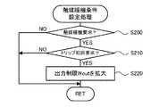
図4の触媒暖機条件設定処理が実行されると、エンジンECU24は、まず、触媒暖機要求が出力されているか否かを判定する(ステップS200)。この判定は、例えば触媒暖機要求フラグに値1がセットされているか否かを調べることによって行なうことができる。触媒暖機要求が出力されていないときには、触媒暖機は行なわれないので触媒暖機条件の設定を行なうことなく、本処理を終了する。触媒暖機要求が出力されているときには、車両をシステム起動してから初回の触媒暖機要求の出力であるか否かを判定する(ステップS210)。そして、初回の触媒暖機要求の出力であるときには、バッテリ50の出力制限Woutの拡大を指示して(ステップS220)、本処理を終了する。一方、初回の触媒暖機要求の出力ではないときには、バッテリ50の出力制限Woutの拡大を指示することなく、本処理を終了する。バッテリ50の出力制限Woutの拡大が指示されると、HVECU70は、バッテリECU52から送信されるバッテリ50の出力制限Woutを所定電力ΔWだけ拡大して得られる新たな出力制限Woutを用いて駆動制御(モータMG1のトルク指令Tm1*やモータMG2のトルク指令Tm2*の設定)を行なう。なお、バッテリ50の出力制限Woutの拡大は、バッテリ50から出力してもよい最大電力を大きくすることを意味している。 When the catalyst warm-up condition setting process in FIG. 4 is executed, the
システム起動から初回の触媒暖機制御は、エンジン22の点火時期を基準位置から予め定められた遅角量Δθ1だけ遅角(遅く)した状態で、エンジン22をある程度の負荷運転で運転することができるように予め定められた吸入空気量Qa1となるようにスロットル開度THが調整される。そして、バッテリ50の出力制限Woutを予め定められた所定電力ΔWだけ拡大する。エンジン22の点火時期を遅角(遅く)するのは、爆発燃焼のタイミングを遅くして、より多くの燃焼エネルギを排気に含ませ、触媒暖機を良好に行なうためである。エンジン22を負荷運転するのは、エンジン22を無負荷運転すると、点火時期を遅角しているため燃焼が緩慢になってトルク変動が生じやすくなり、このトルク変動によりギヤのガタ打ち等による異音が生じるのを抑制すためである。バッテリ50の出力制限Woutを拡大するのは、触媒暖機中はエンジン22からの動力を走行用の動力として充分に用いることができないため、モータMG2からの出力が大きくなり、バッテリ50からのより大きな出力が必要となるからである。 In the first catalyst warm-up control after system startup, the
システム起動から2回目以降の触媒暖機制御では、バッテリ50の出力制限Woutの拡大を行うことなく、エンジン22の点火時期を基準位置から遅角量Δθだけ遅角(遅く)した状態で、エンジン22を負荷運転して行われる。このように2回目以降の触媒暖機要求の出力に対してバッテリ50の出力制限Woutの拡大を行なわないことにより、バッテリ50の過大な電力の出力を抑制することができ、バッテリ50の劣化を抑制することができる。 In the catalyst warm-up control for the second and subsequent times after system start-up, the
以上説明した第1実施例のハイブリッド自動車20では、車両をシステム起動してから2回目以降にエンジン22を始動するときに触媒温度Tcが所定温度Tcset未満のときには、浄化装置134の触媒を暖機するために触媒暖機要求を出力する。そして、車両をシステム起動してから2回目以降の触媒暖機要求の出力に対しては、初回の触媒暖機要求の出力であるときに実行されるバッテリ50の出力制限Woutの拡大を行なわない。このため、システム起動してから2回目以降の触媒暖機要求の出力に対する触媒暖機では、バッテリ50の過大な電力の出力を抑制することができ、バッテリ50の劣化を抑制することができる。もとより、システム起動してから2回目以降の触媒暖機要求の出力に対して触媒暖機を行なうから、エミッションの悪化を抑制することができる。これらの結果、バッテリ50の劣化の抑制とエミッションの悪化の抑制との調和(両立)を図ることができる。 In the
第1実施例のハイブリッド自動車20では、システム起動してから2回目以降の触媒暖機要求の出力に対しては、バッテリ50の出力制限Woutの拡大を行なわないものとしたが、バッテリ50の出力制限Woutの拡大を制限すればよいから、拡大量を小さくするものとしても構わない。 In the
次に、本発明の第2実施例のハイブリッド自動車220について説明する。第2実施例のハイブリッド自動車220は、触媒暖機条件設定処理が異なるだけで図1および図2を用いて説明した第1実施例のハイブリッド自動車20と同一の構成をしている。重複する記載を回避するため、第2実施例のハイブリッド自動車220の構成についての説明は省略する。 Next, a
第2実施例のハイブリッド自動車220でも図3に例示した触媒暖機判定処理が実行され、図5に例示する触媒暖機条件設定処理が実行される。以下、図5の触媒暖機条件設定処理について説明する。 Also in the
図5の触媒暖機条件設定処理が実行されると、第2実施例のハイブリッド自動車220のエンジンECU24は、まず、触媒暖機を実施中であるか否かを判定する(ステップS300)。触媒暖機を実施していないときには、触媒暖機の条件を設定する必要がないため、本処理を終了する。触媒暖機を実施中のときには、車両をシステム起動してから初回の触媒暖機の実施であるか否かを判定する(ステップS310)。そして、初回の触媒暖機の実施であるときには、初回用の吸入空気量と点火時期とを設定して(ステップS320)、本処理を終了する。一方、初回の触媒暖機の実施ではないとき、即ち、システム起動してから2回目以降の触媒暖機の実施のときには、2回目以降用の吸入空気量と点火時期とを設定して(ステップS330)、本処理を終了する。ここで、初回用の点火時期は、第1実施例で説明したように、基準位置から遅角量Δθ1だけ遅角(遅く)した時期が用いられる。また、初回用の吸入空気量についても第1実施例で説明したように、エンジン22をある程度の負荷運転で運転するように予め定められた吸入空気量Qa1が用いられる。2回目以降の点火時期は、初回用の点火時期より遅角量Δθ1が制限された時期、即ち、通常の点火時期より遅角(遅く)しているが初回用の点火時期より進角(早く)した時期を用いる。例えば、遅角量Δθ1より小さな値の遅角量Δθ2だけ基準位置から遅角(遅く)した時期を用いることができる。また、2回目以降用の吸入空気量は、2回目以降用の点火時期としたときにエンジン22をある程度の負荷運転で運転することができる吸入空気量Qa2が用いられる。2回目以降用の点火時期は初回用の点火時期より進角(早く)しているから、燃焼の緩慢さが抑制され、同一の吸入空気量とするとエンジン22からの出力が大きくなる。このため、2回目以降用の吸入空気量が初回用の吸入空気量より小さくなるようにするのが好ましい。このように、2回目以降の点火時期を初回用の点火時期より遅角量Δθを制限したものを用いることにより、初回の触媒暖機に比してエンジン22の運転を安定させ、バッテリ50からの出力が過度にならないようにしてバッテリ50の劣化を抑制することができる。 When the catalyst warm-up condition setting process of FIG. 5 is executed, the
以上説明した第2実施例のハイブリッド自動車220では、車両をシステム起動してから2回目以降にエンジン22を始動するときに触媒温度Tcが所定温度Tcset未満のときには、浄化装置134の触媒を暖機するために触媒暖機要求を出力する。そして、車両をシステム起動してから2回目以降の触媒暖機の実施の際には、エンジン22の点火時期を通常の点火時期より遅角(遅く)するが初回の触媒暖機の実施の際のエンジン22の点火時期より進角した時期を用いる。このため、初回の触媒暖機に比してエンジン22の運転を安定させ、バッテリ50からの出力が過度にならないようにしてバッテリ50の劣化を抑制することができる。もとより、システム起動してから2回目以降の触媒暖機の実施により、エミッションの悪化を抑制することができる。これらの結果、バッテリ50の劣化の抑制とエミッションの悪化の抑制との調和(両立)を図ることができる。 In the
次に、本発明の第3実施例のハイブリッド自動車320について説明する。第3実施例のハイブリッド自動車320は、触媒暖機条件設定処理が異なるだけで図1および図2を用いて説明した第1実施例のハイブリッド自動車20と同一の構成をしている。重複する記載を回避するため、第3実施例のハイブリッド自動車320の構成についての説明は省略する。 Next, a
第3実施例のハイブリッド自動車320でも図3に例示した触媒暖機判定処理が実行され、図6に例示する触媒暖機条件設定処理が実行される。以下、図6の触媒暖機条件設定処理について説明する。 Also in the
図6の触媒暖機条件設定処理が実行されると、第3実施例のハイブリッド自動車320のエンジンECU24は、まず、触媒暖機要求が出力されているか否かを判定する(ステップS400)。触媒暖機要求が出力されていないときには、触媒暖機の条件を設定する必要がないため、本処理を終了する。触媒暖機要求が出力されているときには、車両をシステム起動してから初回の触媒暖機要求の出力であるか否かを判定する(ステップS410)。そして、初回の触媒暖機要求の出力であるときには、触媒暖機を継続することができる最大時間(許可時間)として初回用の許可時間を設定して(ステップS420)、本処理を終了する。一方、初回の触媒暖機要求の出力ではないとき、即ち、システム起動してから2回目以降の触媒暖機要求の出力のときには、初回用の許可時間より短い2回目以降用の許可時間を設定して(ステップS430)、本処理を終了する。システム起動してから2回目以降の触媒暖機要求の出力のときには、触媒暖機を継続することができる許可時間を制限するのである。触媒暖機を継続する時間が長くなると、その分だけ触媒暖機に伴うバッテリ50の充放電の時間も長くなる。したがって、触媒暖機を継続する許可時間を短くすることにより、触媒暖機に伴うバッテリ50の充放電の時間を短くすることができ、バッテリ50の劣化を抑制することができる。 When the catalyst warm-up condition setting process of FIG. 6 is executed, the
以上説明した第3実施例のハイブリッド自動車320では、車両をシステム起動してから2回目以降にエンジン22を始動するときに触媒温度Tcが所定温度Tcset未満のときには、浄化装置134の触媒を暖機するために触媒暖機要求を出力する。そして、車両をシステム起動してから2回目以降の触媒暖機要求の出力の際には、触媒暖機を継続してもよい最大時間としての許可時間として初回の触媒暖機要求の出力の際の許可時間より短い時間を用いる。このため、触媒暖機を継続する時間が短くなり、触媒暖機に伴うバッテリ50の充放電の時間を短くして、バッテリ50の劣化を抑制することができる。もとより、システム起動してから2回目以降の触媒暖機要求の出力に対しても触媒暖機を行なうから、エミッションの悪化を抑制することができる。これらの結果、バッテリ50の劣化の抑制とエミッションの悪化の抑制との調和(両立)を図ることができる。 In the
触媒暖機条件設定処理として、第1実施例ではバッテリ50の出力制限Woutの拡大の制限について、第2実施例ではエンジン22の点火時期の遅角量の制限について、第3実施例では許可時間の制限について、独立に成立するものとして説明した。しかし、これらの3つの制限のうちいずれか2つを組み合わせて用いるものとしたり、3つの制限の全てを組み合わせて用いるものとしてもよい。 As the catalyst warm-up condition setting process, in the first embodiment, the expansion limit of the output limit Wout of the
第1実施例ないし第3実施例のハイブリッド自動車20,220,320では、発電機としても電動機としても機能する2つのモータMG1,MG2とエンジン22とをプラネタリギヤ30により接続する構成を用いたが、走行用の動力を出力可能なエンジンと、エンジンの動力により発電する発電機と、走行用の動力を出力可能な電動機と、を備える構成であれば如何なる構成としても差し支えない。 In the
以上、本発明を実施するための形態について実施例を用いて説明したが、本発明はこうした実施例に何等限定されるものではなく、本発明の要旨を逸脱しない範囲内において、種々なる形態で実施し得ることは勿論である。 As mentioned above, although the form for implementing this invention was demonstrated using the Example, this invention is not limited at all to such an Example, In the range which does not deviate from the summary of this invention, it is with various forms. Of course, it can be implemented.
本発明は、ハイブリッド自動車の製造産業などに利用可能である。 The present invention can be used in the manufacturing industry of hybrid vehicles.
20,220,320 ハイブリッド自動車、22 エンジン、24 エンジン用電子制御ユニット(エンジンECU)、24a CPU、24b ROM、24c RAM、26 クランクシャフト、30 プラネタリギヤ、32 駆動軸、40 モータ用電子制御ユニット(モータECU)、41,42 インバータ、50 バッテリ、52 バッテリ用電子制御ユニット(バッテリECU)、62 デファレンシャルギヤ、63a,63b 駆動輪、70 ハイブリッド用電子制御ユニット、80 イグニッションスイッチ、81 シフトレバー、82 シフトポジションセンサ、83 アクセルペダル、84 アクセルペダルポジションセンサ、85 ブレーキペダル、86 ブレーキペダルポジションセンサ、88 車速センサ、122 エアクリーナ、124 スロットルバルブ、126 燃料噴射弁、128 吸気バルブ、130 点火プラグ、132 ピストン、134 浄化装置、134a 温度センサ、135a 空燃比センサ、135b 酸素センサ、136,スロットルモータ、138 イグニッションコイル、140 クランクポジションセンサ、142 水温センサ、144 カムポジションセンサ、146 スロットルバルブポジションセンサ、148 エアフローメータ、149 温度センサ、150 可変バルブタイミング機構、158 吸気圧センサ、159 ノックセンサ、160 EGRシステム、162 EGR管、163 ステッピングモータ、164 EGRバルブ、165 EGRバルブ開度センサ、MG1,MG2 モータ。 20, 220, 320 Hybrid vehicle, 22 engine, 24 engine electronic control unit (engine ECU), 24a CPU, 24b ROM, 24c RAM, 26 crankshaft, 30 planetary gear, 32 drive shaft, 40 electronic control unit for motor (motor) ECU), 41, 42 inverter, 50 battery, 52 battery electronic control unit (battery ECU), 62 differential gear, 63a, 63b drive wheel, 70 hybrid electronic control unit, 80 ignition switch, 81 shift lever, 82 shift position Sensor, 83 Accelerator pedal, 84 Accelerator pedal position sensor, 85 Brake pedal, 86 Brake pedal position sensor, 88 Vehicle speed sensor, 122 Air cleaner , 124 throttle valve, 126 fuel injection valve, 128 intake valve, 130 spark plug, 132 piston, 134 purification device, 134a temperature sensor, 135a air-fuel ratio sensor, 135b oxygen sensor, 136, throttle motor, 138 ignition coil, 140 crank Position sensor, 142 Water temperature sensor, 144 Cam position sensor, 146 Throttle valve position sensor, 148 Air flow meter, 149 Temperature sensor, 150 Variable valve timing mechanism, 158 Intake pressure sensor, 159 Knock sensor, 160 EGR system, 162 EGR pipe, 163 Stepping motor, 164 EGR valve, 165 EGR valve opening sensor, MG1, MG2 motor.
Claims (4)
Translated fromJapanese前記制御手段は、システム起動後に2回目以降に前記内燃機関を始動するときに前記内燃機関の排気浄化装置の触媒の暖機が必要なときには前記第1触媒暖機制御に比して制限を課して前記内燃機関の負荷運転によって前記触媒の暖機を行なう第2触媒暖機制御を実行する手段である、
ことを特徴とするハイブリッド自動車。An internal combustion engine that can output power for traveling, a generator that generates power using the power of the internal combustion engine, an electric motor that can output power for traveling, a battery that exchanges electric power with the generator and the motor, and When the internal combustion engine is started for the first time after the system is started, when the catalyst of the exhaust purification device of the internal combustion engine needs to be warmed up, the catalyst is warmed upby a load operation of the internal combustion engine with a predetermined intake air amount . A hybrid vehicle comprising: a control means for performing 1 catalyst warm-up control;
The control means imposes a limit as compared with the first catalyst warm-up control when the internal combustion engine needs to be warmed up when the internal combustion engine is started for the second time or later after system startup. And means for executing second catalyst warm-up control for warming up the catalystby load operation of the internal combustion engine .
A hybrid vehicle characterized by that.
前記第1触媒暖機制御は、前記バッテリから放電してもよい最大電力である出力制限を拡大して行なう制御であり、
前記第2触媒暖機制御は、前記第1触媒暖機制御に比して前記出力制限の拡大を制限して行なう制御である、
ハイブリッド自動車。The hybrid vehicle according to claim 1,
The first catalyst warm-up control is a control performed by expanding an output limit that is the maximum power that may be discharged from the battery,
The second catalyst warm-up control is control performed by restricting expansion of the output restriction as compared with the first catalyst warm-up control.
Hybrid car.
前記第1触媒暖機制御は、前記内燃機関の点火時期を遅角して行なう制御であり、
前記第2触媒暖機制御は、前記第1触媒暖機制御に比して前記点火時期の遅角を制限して行なう制御である、
ハイブリッド自動車。A hybrid vehicle according to claim 1 or 2,
The first catalyst warm-up control is control performed by retarding the ignition timing of the internal combustion engine,
The second catalyst warm-up control is control performed by limiting a retard angle of the ignition timing as compared with the first catalyst warm-up control.
Hybrid car.
前記第1触媒暖機制御は、第1許可時間の範囲内で実行する制御であり、
前記第2触媒暖機制御は、前記第1許可時間より短い第2許可時間の範囲内で実行する制御である、
ハイブリッド自動車。A hybrid vehicle according to any one of claims 1 to 3,
The first catalyst warm-up control is a control executed within a range of a first permission time;
The second catalyst warm-up control is a control executed within a range of a second permission time shorter than the first permission time.
Hybrid car.
Priority Applications (4)
| Application Number | Priority Date | Filing Date | Title |
|---|---|---|---|
| JP2014215466AJP6149841B2 (en) | 2014-10-22 | 2014-10-22 | Hybrid car |
| EP15190855.5AEP3012140B1 (en) | 2014-10-22 | 2015-10-21 | Hybrid vehicle |
| US14/918,885US9821794B2 (en) | 2014-10-22 | 2015-10-21 | Hybrid vehicle |
| CN201510691450.4ACN105545502B (en) | 2014-10-22 | 2015-10-22 | Hybrid electric vehicle |
Applications Claiming Priority (1)
| Application Number | Priority Date | Filing Date | Title |
|---|---|---|---|
| JP2014215466AJP6149841B2 (en) | 2014-10-22 | 2014-10-22 | Hybrid car |
Publications (2)
| Publication Number | Publication Date |
|---|---|
| JP2016078802A JP2016078802A (en) | 2016-05-16 |
| JP6149841B2true JP6149841B2 (en) | 2017-06-21 |
Family
ID=54364986
Family Applications (1)
| Application Number | Title | Priority Date | Filing Date |
|---|---|---|---|
| JP2014215466AActiveJP6149841B2 (en) | 2014-10-22 | 2014-10-22 | Hybrid car |
Country Status (4)
| Country | Link |
|---|---|
| US (1) | US9821794B2 (en) |
| EP (1) | EP3012140B1 (en) |
| JP (1) | JP6149841B2 (en) |
| CN (1) | CN105545502B (en) |
Families Citing this family (12)
| Publication number | Priority date | Publication date | Assignee | Title |
|---|---|---|---|---|
| US20040037828A1 (en) | 2002-07-09 | 2004-02-26 | Bar-Ilan University | Methods and pharmaceutical compositions for healing wounds |
| JP6767673B2 (en) | 2016-09-29 | 2020-10-14 | 三菱自動車工業株式会社 | Hybrid vehicle control device |
| JP6544342B2 (en)* | 2016-11-29 | 2019-07-17 | トヨタ自動車株式会社 | Hybrid car |
| DE102017100878A1 (en)* | 2017-01-18 | 2017-03-09 | Fev Gmbh | Hybrid motor vehicle and method for operating a hybrid motor vehicle |
| JP6954051B2 (en)* | 2017-11-27 | 2021-10-27 | トヨタ自動車株式会社 | Hybrid car |
| JP6935751B2 (en)* | 2018-01-15 | 2021-09-15 | トヨタ自動車株式会社 | Hybrid vehicle |
| JP6828705B2 (en)* | 2018-03-12 | 2021-02-10 | トヨタ自動車株式会社 | Vehicle control device |
| JP7310461B2 (en)* | 2019-09-03 | 2023-07-19 | トヨタ自動車株式会社 | power train system |
| JP7364524B2 (en)* | 2020-04-01 | 2023-10-18 | トヨタ自動車株式会社 | Vehicle control device, vehicle control method, and vehicle control system |
| JP7714914B2 (en)* | 2021-05-31 | 2025-07-30 | マツダ株式会社 | Electric vehicle control device |
| US11753599B2 (en) | 2021-06-04 | 2023-09-12 | Afton Chemical Corporation | Lubricating compositions for a hybrid engine |
| JP2024050158A (en) | 2022-09-29 | 2024-04-10 | トヨタ自動車株式会社 | Vehicle control device |
Family Cites Families (12)
| Publication number | Priority date | Publication date | Assignee | Title |
|---|---|---|---|---|
| JP3933096B2 (en) | 2003-06-03 | 2007-06-20 | トヨタ自動車株式会社 | Battery control device and control method mounted on vehicle |
| JP2007302185A (en) | 2006-05-15 | 2007-11-22 | Toyota Motor Corp | POWER OUTPUT DEVICE, ITS CONTROL METHOD, AND VEHICLE |
| KR100783890B1 (en)* | 2006-09-18 | 2007-12-10 | 현대자동차주식회사 | Catalyst Heating Control Method for Parallel Hybrid Vehicles |
| JP4197038B2 (en) | 2007-03-27 | 2008-12-17 | トヨタ自動車株式会社 | Hybrid vehicle and control method thereof |
| JP4325704B2 (en)* | 2007-06-06 | 2009-09-02 | トヨタ自動車株式会社 | Exhaust gas purification system for internal combustion engine |
| JP2009214704A (en)* | 2008-03-11 | 2009-09-24 | Nissan Motor Co Ltd | Start control device for engine |
| JPWO2010100748A1 (en)* | 2009-03-06 | 2012-09-06 | トヨタ自動車株式会社 | Control device and control method for hybrid vehicle |
| WO2010134163A1 (en)* | 2009-05-19 | 2010-11-25 | トヨタ自動車株式会社 | Hybrid vehicle and control method of same |
| JP5229386B2 (en)* | 2009-05-25 | 2013-07-03 | トヨタ自動車株式会社 | Hybrid vehicle and control method thereof |
| JP5278963B2 (en)* | 2009-07-30 | 2013-09-04 | 本田技研工業株式会社 | Vehicle control device |
| JP5429366B2 (en) | 2010-04-07 | 2014-02-26 | トヨタ自動車株式会社 | Control device for hybrid vehicle and hybrid vehicle including the same |
| US8989935B2 (en)* | 2013-03-22 | 2015-03-24 | Ford Global Technologies, Llc | Method and system for engine control |
- 2014
- 2014-10-22JPJP2014215466Apatent/JP6149841B2/enactiveActive
- 2015
- 2015-10-21USUS14/918,885patent/US9821794B2/enactiveActive
- 2015-10-21EPEP15190855.5Apatent/EP3012140B1/ennot_activeNot-in-force
- 2015-10-22CNCN201510691450.4Apatent/CN105545502B/ennot_activeExpired - Fee Related
Also Published As
| Publication number | Publication date |
|---|---|
| US9821794B2 (en) | 2017-11-21 |
| US20160114791A1 (en) | 2016-04-28 |
| CN105545502A (en) | 2016-05-04 |
| JP2016078802A (en) | 2016-05-16 |
| EP3012140B1 (en) | 2018-06-13 |
| EP3012140A1 (en) | 2016-04-27 |
| CN105545502B (en) | 2018-06-05 |
Similar Documents
| Publication | Publication Date | Title |
|---|---|---|
| JP6149841B2 (en) | Hybrid car | |
| JP4197038B2 (en) | Hybrid vehicle and control method thereof | |
| JP6248997B2 (en) | Hybrid car | |
| JP2010241170A (en) | Power output apparatus, hybrid vehicle provided with the same, and method of controlling power output apparatus | |
| JP2013193533A (en) | Hybrid vehicle | |
| KR20160067745A (en) | Automobile | |
| JP5904131B2 (en) | Hybrid vehicle control device and hybrid vehicle | |
| JP2009052487A (en) | Vehicle and control method of internal combustion engine mounted on vehicle | |
| WO2006038306A1 (en) | Device and method for controlling internal combustion engine | |
| JP5751185B2 (en) | Hybrid car | |
| CN106121842B (en) | hybrid vehicle | |
| JP2013112101A (en) | Hybrid vehicle | |
| JP2010105626A (en) | Vehicle and control method therefor | |
| JP2010195306A (en) | Hybrid car and method for controlling the same | |
| JP5692008B2 (en) | Hybrid car | |
| JP2007309113A (en) | POWER OUTPUT DEVICE, VEHICLE HAVING THE SAME, AND METHOD FOR CONTROLLING POWER OUTPUT DEVICE | |
| JP5991145B2 (en) | Hybrid car | |
| JP2013100054A (en) | Ignition timing control device | |
| JP7581981B2 (en) | Hybrid Vehicles | |
| JP2013067297A (en) | Hybrid vehicle | |
| JP2006070820A (en) | Drive device, automobile equipped with the same and method for controlling the drive device | |
| JP2018200028A (en) | Control device for internal combustion engine | |
| JP2011069349A (en) | Power output device, hybrid vehicle, and method of determining condition of variable valve timing mechanism | |
| JP6277972B2 (en) | Hybrid car | |
| JP2012236548A (en) | Hybrid vehicle |
Legal Events
| Date | Code | Title | Description |
|---|---|---|---|
| A621 | Written request for application examination | Free format text:JAPANESE INTERMEDIATE CODE: A621 Effective date:20160211 | |
| A977 | Report on retrieval | Free format text:JAPANESE INTERMEDIATE CODE: A971007 Effective date:20161011 | |
| A131 | Notification of reasons for refusal | Free format text:JAPANESE INTERMEDIATE CODE: A131 Effective date:20161018 | |
| A521 | Written amendment | Free format text:JAPANESE INTERMEDIATE CODE: A523 Effective date:20161207 | |
| TRDD | Decision of grant or rejection written | ||
| A01 | Written decision to grant a patent or to grant a registration (utility model) | Free format text:JAPANESE INTERMEDIATE CODE: A01 Effective date:20170425 | |
| A61 | First payment of annual fees (during grant procedure) | Free format text:JAPANESE INTERMEDIATE CODE: A61 Effective date:20170508 | |
| R151 | Written notification of patent or utility model registration | Ref document number:6149841 Country of ref document:JP Free format text:JAPANESE INTERMEDIATE CODE: R151 |