JP6147747B2 - Transparent implant made of PEEK or PMMA with an uncured polymer adhesive layer - Google Patents
Transparent implant made of PEEK or PMMA with an uncured polymer adhesive layerDownload PDFInfo
- Publication number
- JP6147747B2 JP6147747B2JP2014527321AJP2014527321AJP6147747B2JP 6147747 B2JP6147747 B2JP 6147747B2JP 2014527321 AJP2014527321 AJP 2014527321AJP 2014527321 AJP2014527321 AJP 2014527321AJP 6147747 B2JP6147747 B2JP 6147747B2
- Authority
- JP
- Japan
- Prior art keywords
- implant
- bone
- polymerizable
- layer
- crosslinkable material
- Prior art date
- Legal status (The legal status is an assumption and is not a legal conclusion. Google has not performed a legal analysis and makes no representation as to the accuracy of the status listed.)
- Expired - Fee Related
Links
- 239000007943implantSubstances0.000titleclaimsdescription145
- 229920000642polymerPolymers0.000titleclaimsdescription30
- 239000004696Poly ether ether ketoneSubstances0.000titleclaimsdescription10
- 229920003229poly(methyl methacrylate)Polymers0.000titleclaimsdescription10
- 229920002530polyetherether ketonePolymers0.000titleclaimsdescription10
- 239000004926polymethyl methacrylateSubstances0.000titleclaimsdescription10
- 239000012790adhesive layerSubstances0.000titledescription2
- JUPQTSLXMOCDHR-UHFFFAOYSA-Nbenzene-1,4-diol;bis(4-fluorophenyl)methanoneChemical compoundOC1=CC=C(O)C=C1.C1=CC(F)=CC=C1C(=O)C1=CC=C(F)C=C1JUPQTSLXMOCDHR-UHFFFAOYSA-N0.000title1
- 210000000988bone and boneAnatomy0.000claimsdescription167
- 239000000463materialSubstances0.000claimsdescription118
- 239000000178monomerSubstances0.000claimsdescription14
- 238000003780insertionMethods0.000claimsdescription10
- 230000037431insertionEffects0.000claimsdescription10
- 239000000203mixtureSubstances0.000claimsdescription10
- 239000004814polyurethaneSubstances0.000claimsdescription9
- 229920002635polyurethanePolymers0.000claimsdescription9
- 150000003839saltsChemical class0.000claimsdescription8
- 150000001447alkali saltsChemical class0.000claimsdescription7
- 125000000217alkyl groupChemical group0.000claimsdescription5
- 230000005855radiationEffects0.000claimsdescription5
- 229920001651CyanoacrylatePolymers0.000claimsdescription4
- MWCLLHOVUTZFKS-UHFFFAOYSA-NMethyl cyanoacrylateChemical compoundCOC(=O)C(=C)C#NMWCLLHOVUTZFKS-UHFFFAOYSA-N0.000claimsdescription4
- 229910019142PO4Inorganic materials0.000claimsdescription4
- 239000000853adhesiveSubstances0.000claimsdescription4
- 230000001070adhesive effectEffects0.000claimsdescription4
- 125000003342alkenyl groupChemical group0.000claimsdescription4
- 125000002877alkyl aryl groupChemical group0.000claimsdescription4
- 125000005599alkyl carboxylate groupChemical group0.000claimsdescription4
- 125000005119alkyl cycloalkyl groupChemical group0.000claimsdescription4
- 150000008051alkyl sulfatesChemical class0.000claimsdescription4
- 125000003118aryl groupChemical group0.000claimsdescription4
- 239000003822epoxy resinSubstances0.000claimsdescription4
- -1or -sulfateSubstances0.000claimsdescription4
- 239000010452phosphateSubstances0.000claimsdescription4
- 229920000647polyepoxidePolymers0.000claimsdescription4
- 229920006395saturated elastomerPolymers0.000claimsdescription4
- 108010073385FibrinProteins0.000claimsdescription2
- 102000009123FibrinHuman genes0.000claimsdescription2
- BWGVNKXGVNDBDI-UHFFFAOYSA-NFibrin monomerChemical compoundCNC(=O)CNC(=O)CNBWGVNKXGVNDBDI-UHFFFAOYSA-N0.000claimsdescription2
- 229950003499fibrinDrugs0.000claimsdescription2
- LNEPOXFFQSENCJ-UHFFFAOYSA-NhaloperidolChemical compoundC1CC(O)(C=2C=CC(Cl)=CC=2)CCN1CCCC(=O)C1=CC=C(F)C=C1LNEPOXFFQSENCJ-UHFFFAOYSA-N0.000claimsdescription2
- 239000010410layerSubstances0.000description112
- 238000000034methodMethods0.000description24
- 239000012634fragmentSubstances0.000description16
- 230000004913activationEffects0.000description12
- 230000003213activating effectEffects0.000description9
- 238000004132cross linkingMethods0.000description8
- 230000009467reductionEffects0.000description8
- 210000004872soft tissueAnatomy0.000description8
- 208000010392Bone FracturesDiseases0.000description7
- 206010017076FractureDiseases0.000description7
- 230000008901benefitEffects0.000description7
- 230000037303wrinklesEffects0.000description6
- 238000004873anchoringMethods0.000description5
- 239000012948isocyanateSubstances0.000description5
- 150000002513isocyanatesChemical class0.000description5
- 208000006735PeriostitisDiseases0.000description4
- 238000002513implantationMethods0.000description4
- 210000003460periosteumAnatomy0.000description4
- 238000006116polymerization reactionMethods0.000description4
- 230000000379polymerizing effectEffects0.000description4
- 239000003054catalystSubstances0.000description3
- 125000000753cycloalkyl groupChemical group0.000description3
- POULHZVOKOAJMA-UHFFFAOYSA-MdodecanoateChemical groupCCCCCCCCCCCC([O-])=OPOULHZVOKOAJMA-UHFFFAOYSA-M0.000description3
- MOTZDAYCYVMXPC-UHFFFAOYSA-Ndodecyl hydrogen sulfateChemical compoundCCCCCCCCCCCCOS(O)(=O)=OMOTZDAYCYVMXPC-UHFFFAOYSA-N0.000description3
- 229940043264dodecyl sulfateDrugs0.000description3
- IPCSVZSSVZVIGE-UHFFFAOYSA-MhexadecanoateChemical compoundCCCCCCCCCCCCCCCC([O-])=OIPCSVZSSVZVIGE-UHFFFAOYSA-M0.000description3
- 229940070765laurateDrugs0.000description3
- 229940105132myristateDrugs0.000description3
- QIQXTHQIDYTFRH-UHFFFAOYSA-Noctadecanoic acidChemical compoundCCCCCCCCCCCCCCCCCC(O)=OQIQXTHQIDYTFRH-UHFFFAOYSA-N0.000description3
- 229940049964oleateDrugs0.000description3
- ZQPPMHVWECSIRJ-KTKRTIGZSA-Noleic acidChemical compoundCCCCCCCC\C=C/CCCCCCCC(O)=OZQPPMHVWECSIRJ-KTKRTIGZSA-N0.000description3
- 230000000149penetrating effectEffects0.000description3
- 238000003825pressingMethods0.000description3
- TUNFSRHWOTWDNC-UHFFFAOYSA-Ntetradecanoic acidChemical compoundCCCCCCCCCCCCCC(O)=OTUNFSRHWOTWDNC-UHFFFAOYSA-N0.000description3
- 108010080379Fibrin Tissue AdhesiveProteins0.000description2
- CERQOIWHTDAKMF-UHFFFAOYSA-NMethacrylic acidChemical compoundCC(=C)C(O)=OCERQOIWHTDAKMF-UHFFFAOYSA-N0.000description2
- VVQNEPGJFQJSBK-UHFFFAOYSA-NMethyl methacrylateChemical compoundCOC(=O)C(C)=CVVQNEPGJFQJSBK-UHFFFAOYSA-N0.000description2
- UKMSUNONTOPOIO-UHFFFAOYSA-MbehenateChemical compoundCCCCCCCCCCCCCCCCCCCCCC([O-])=OUKMSUNONTOPOIO-UHFFFAOYSA-M0.000description2
- 229940116224behenateDrugs0.000description2
- 230000002301combined effectEffects0.000description2
- 230000000694effectsEffects0.000description2
- 238000004519manufacturing processMethods0.000description2
- 230000004048modificationEffects0.000description2
- 238000012986modificationMethods0.000description2
- 230000008569processEffects0.000description2
- 239000000126substanceSubstances0.000description2
- 239000012780transparent materialSubstances0.000description2
- RMCCONIRBZIDTH-UHFFFAOYSA-N2-(2-methylprop-2-enoyloxy)ethyl 1,3-dioxo-2-benzofuran-5-carboxylateChemical compoundCC(=C)C(=O)OCCOC(=O)C1=CC=C2C(=O)OC(=O)C2=C1RMCCONIRBZIDTH-UHFFFAOYSA-N0.000description1
- 206010073306Exposure to radiationDiseases0.000description1
- 206010019114Hand fractureDiseases0.000description1
- 239000002253acidSubstances0.000description1
- 230000002378acidificating effectEffects0.000description1
- 230000004075alterationEffects0.000description1
- 150000001413amino acidsChemical class0.000description1
- 239000002585baseSubstances0.000description1
- 229920000249biocompatible polymerPolymers0.000description1
- 125000003636chemical groupChemical group0.000description1
- 230000001054cortical effectEffects0.000description1
- 230000008878couplingEffects0.000description1
- 238000010168coupling processMethods0.000description1
- 238000005859coupling reactionMethods0.000description1
- 238000005553drillingMethods0.000description1
- 229920001971elastomerPolymers0.000description1
- 239000000806elastomerSubstances0.000description1
- 210000000744eyelidAnatomy0.000description1
- 239000011521glassSubstances0.000description1
- 230000002209hydrophobic effectEffects0.000description1
- 230000001678irradiating effectEffects0.000description1
- 230000013011matingEffects0.000description1
- 210000000236metacarpal boneAnatomy0.000description1
- 239000002861polymer materialSubstances0.000description1
- 229920001296polysiloxanePolymers0.000description1
- 230000002028prematureEffects0.000description1
- 108090000623proteins and genesProteins0.000description1
- 102000004169proteins and genesHuman genes0.000description1
- 239000011347resinSubstances0.000description1
- 229920005989resinPolymers0.000description1
- 238000000926separation methodMethods0.000description1
- 230000001568sexual effectEffects0.000description1
- 239000004071sootSubstances0.000description1
- 238000006467substitution reactionMethods0.000description1
- 238000001356surgical procedureMethods0.000description1
- 229920001169thermoplasticPolymers0.000description1
- 229920001187thermosetting polymerPolymers0.000description1
- 239000004416thermosoftening plasticSubstances0.000description1
- 229920006352transparent thermoplasticPolymers0.000description1
- SRPWOOOHEPICQU-UHFFFAOYSA-Ntrimellitic anhydrideChemical compoundOC(=O)C1=CC=C2C(=O)OC(=O)C2=C1SRPWOOOHEPICQU-UHFFFAOYSA-N0.000description1
Images


Classifications
- A—HUMAN NECESSITIES
- A61—MEDICAL OR VETERINARY SCIENCE; HYGIENE
- A61B—DIAGNOSIS; SURGERY; IDENTIFICATION
- A61B17/00—Surgical instruments, devices or methods
- A61B17/56—Surgical instruments or methods for treatment of bones or joints; Devices specially adapted therefor
- A61B17/58—Surgical instruments or methods for treatment of bones or joints; Devices specially adapted therefor for osteosynthesis, e.g. bone plates, screws or setting implements
- A61B17/68—Internal fixation devices, including fasteners and spinal fixators, even if a part thereof projects from the skin
- A61B17/84—Fasteners therefor or fasteners being internal fixation devices
- A61B17/86—Pins or screws or threaded wires; nuts therefor
- A61B17/866—Material or manufacture
- A—HUMAN NECESSITIES
- A61—MEDICAL OR VETERINARY SCIENCE; HYGIENE
- A61B—DIAGNOSIS; SURGERY; IDENTIFICATION
- A61B17/00—Surgical instruments, devices or methods
- A61B17/56—Surgical instruments or methods for treatment of bones or joints; Devices specially adapted therefor
- A61B17/58—Surgical instruments or methods for treatment of bones or joints; Devices specially adapted therefor for osteosynthesis, e.g. bone plates, screws or setting implements
- A61B17/68—Internal fixation devices, including fasteners and spinal fixators, even if a part thereof projects from the skin
- A61B17/84—Fasteners therefor or fasteners being internal fixation devices
- A61B17/846—Nails or pins, i.e. anchors without movable parts, holding by friction only, with or without structured surface
- A—HUMAN NECESSITIES
- A61—MEDICAL OR VETERINARY SCIENCE; HYGIENE
- A61B—DIAGNOSIS; SURGERY; IDENTIFICATION
- A61B17/00—Surgical instruments, devices or methods
- A61B17/56—Surgical instruments or methods for treatment of bones or joints; Devices specially adapted therefor
- A61B17/58—Surgical instruments or methods for treatment of bones or joints; Devices specially adapted therefor for osteosynthesis, e.g. bone plates, screws or setting implements
- A61B17/68—Internal fixation devices, including fasteners and spinal fixators, even if a part thereof projects from the skin
- A61B17/84—Fasteners therefor or fasteners being internal fixation devices
- A61B17/86—Pins or screws or threaded wires; nuts therefor
- A—HUMAN NECESSITIES
- A61—MEDICAL OR VETERINARY SCIENCE; HYGIENE
- A61L—METHODS OR APPARATUS FOR STERILISING MATERIALS OR OBJECTS IN GENERAL; DISINFECTION, STERILISATION OR DEODORISATION OF AIR; CHEMICAL ASPECTS OF BANDAGES, DRESSINGS, ABSORBENT PADS OR SURGICAL ARTICLES; MATERIALS FOR BANDAGES, DRESSINGS, ABSORBENT PADS OR SURGICAL ARTICLES
- A61L24/00—Surgical adhesives or cements; Adhesives for colostomy devices
- A61L24/04—Surgical adhesives or cements; Adhesives for colostomy devices containing macromolecular materials
- A61L24/046—Surgical adhesives or cements; Adhesives for colostomy devices containing macromolecular materials obtained otherwise than by reactions only involving carbon-to-carbon unsaturated bonds
- A—HUMAN NECESSITIES
- A61—MEDICAL OR VETERINARY SCIENCE; HYGIENE
- A61L—METHODS OR APPARATUS FOR STERILISING MATERIALS OR OBJECTS IN GENERAL; DISINFECTION, STERILISATION OR DEODORISATION OF AIR; CHEMICAL ASPECTS OF BANDAGES, DRESSINGS, ABSORBENT PADS OR SURGICAL ARTICLES; MATERIALS FOR BANDAGES, DRESSINGS, ABSORBENT PADS OR SURGICAL ARTICLES
- A61L24/00—Surgical adhesives or cements; Adhesives for colostomy devices
- A61L24/04—Surgical adhesives or cements; Adhesives for colostomy devices containing macromolecular materials
- A61L24/06—Surgical adhesives or cements; Adhesives for colostomy devices containing macromolecular materials obtained by reactions only involving carbon-to-carbon unsaturated bonds
- A—HUMAN NECESSITIES
- A61—MEDICAL OR VETERINARY SCIENCE; HYGIENE
- A61L—METHODS OR APPARATUS FOR STERILISING MATERIALS OR OBJECTS IN GENERAL; DISINFECTION, STERILISATION OR DEODORISATION OF AIR; CHEMICAL ASPECTS OF BANDAGES, DRESSINGS, ABSORBENT PADS OR SURGICAL ARTICLES; MATERIALS FOR BANDAGES, DRESSINGS, ABSORBENT PADS OR SURGICAL ARTICLES
- A61L27/00—Materials for grafts or prostheses or for coating grafts or prostheses
- A61L27/28—Materials for coating prostheses
- A61L27/34—Macromolecular materials
- A—HUMAN NECESSITIES
- A61—MEDICAL OR VETERINARY SCIENCE; HYGIENE
- A61B—DIAGNOSIS; SURGERY; IDENTIFICATION
- A61B17/00—Surgical instruments, devices or methods
- A61B17/56—Surgical instruments or methods for treatment of bones or joints; Devices specially adapted therefor
- A61B17/58—Surgical instruments or methods for treatment of bones or joints; Devices specially adapted therefor for osteosynthesis, e.g. bone plates, screws or setting implements
- A61B17/60—Surgical instruments or methods for treatment of bones or joints; Devices specially adapted therefor for osteosynthesis, e.g. bone plates, screws or setting implements for external osteosynthesis, e.g. distractors, contractors
- A61B17/66—Alignment, compression or distraction mechanisms
- A—HUMAN NECESSITIES
- A61—MEDICAL OR VETERINARY SCIENCE; HYGIENE
- A61B—DIAGNOSIS; SURGERY; IDENTIFICATION
- A61B17/00—Surgical instruments, devices or methods
- A61B17/56—Surgical instruments or methods for treatment of bones or joints; Devices specially adapted therefor
- A61B17/58—Surgical instruments or methods for treatment of bones or joints; Devices specially adapted therefor for osteosynthesis, e.g. bone plates, screws or setting implements
- A61B17/68—Internal fixation devices, including fasteners and spinal fixators, even if a part thereof projects from the skin
- A61B17/80—Cortical plates, i.e. bone plates; Instruments for holding or positioning cortical plates, or for compressing bones attached to cortical plates
- A61B17/8033—Cortical plates, i.e. bone plates; Instruments for holding or positioning cortical plates, or for compressing bones attached to cortical plates having indirect contact with screw heads, or having contact with screw heads maintained with the aid of additional components, e.g. nuts, wedges or head covers
- A61B17/8042—Cortical plates, i.e. bone plates; Instruments for holding or positioning cortical plates, or for compressing bones attached to cortical plates having indirect contact with screw heads, or having contact with screw heads maintained with the aid of additional components, e.g. nuts, wedges or head covers the additional component being a cover over the screw head
- A—HUMAN NECESSITIES
- A61—MEDICAL OR VETERINARY SCIENCE; HYGIENE
- A61B—DIAGNOSIS; SURGERY; IDENTIFICATION
- A61B17/00—Surgical instruments, devices or methods
- A61B17/56—Surgical instruments or methods for treatment of bones or joints; Devices specially adapted therefor
- A61B17/58—Surgical instruments or methods for treatment of bones or joints; Devices specially adapted therefor for osteosynthesis, e.g. bone plates, screws or setting implements
- A61B17/68—Internal fixation devices, including fasteners and spinal fixators, even if a part thereof projects from the skin
- A61B17/80—Cortical plates, i.e. bone plates; Instruments for holding or positioning cortical plates, or for compressing bones attached to cortical plates
- A61B17/8052—Cortical plates, i.e. bone plates; Instruments for holding or positioning cortical plates, or for compressing bones attached to cortical plates immobilised relative to screws by interlocking form of the heads and plate holes, e.g. conical or threaded
Landscapes
- Health & Medical Sciences (AREA)
- Orthopedic Medicine & Surgery (AREA)
- Life Sciences & Earth Sciences (AREA)
- Surgery (AREA)
- Animal Behavior & Ethology (AREA)
- Veterinary Medicine (AREA)
- Public Health (AREA)
- General Health & Medical Sciences (AREA)
- Chemical & Material Sciences (AREA)
- Engineering & Computer Science (AREA)
- Medical Informatics (AREA)
- Heart & Thoracic Surgery (AREA)
- Biomedical Technology (AREA)
- Nuclear Medicine, Radiotherapy & Molecular Imaging (AREA)
- Neurology (AREA)
- Molecular Biology (AREA)
- Epidemiology (AREA)
- Chemical Kinetics & Catalysis (AREA)
- Medicinal Chemistry (AREA)
- Oral & Maxillofacial Surgery (AREA)
- Transplantation (AREA)
- Dermatology (AREA)
- Materials For Medical Uses (AREA)
- Polymers & Plastics (AREA)
- Organic Chemistry (AREA)
- Surgical Instruments (AREA)
Description
Translated fromJapanese (関連出願の相互参照)
本願は、2011年8月25日に出願された米国仮特許出願第61/527,609号、及び2012年3月12日に出願された米国仮特許出願第61/609,913号に対して優先権を主張するものであり、これら仮特許出願のそれぞれは参照によりその全体が本明細書に組み込まれる。(Cross-reference of related applications)
This application is relative to US Provisional Patent Application No. 61 / 527,609, filed on August 25, 2011, and US Provisional Patent Application No. 61 / 609,913, filed on March 12, 2012. Each of these provisional patent applications is hereby incorporated by reference in its entirety.
(発明の分野)
本発明は、いくつかの実施形態では、一般に、骨に取り付けるためのインプラントに関する。より詳細には、本発明は、いくつかの実施形態では、骨プレートを骨表面に固定するためのインプラント(例えば、鋲)であって、該インプラントの片面は骨接着剤又は重合可能な及び/若しくは架橋可能な材料の層でコーティングされており、プレートの開口部を通して骨表面の上に押し込まれて、確実な接着強度を提供することができる、インプラントに関する。本発明のいくつかの実施形態は、本発明によるインプラントと骨プレートとを含む組立体、及び、本発明によるインプラントを用いた骨プレートの固定方法に関する。(Field of Invention)
The present invention, in some embodiments, generally relates to an implant for attachment to bone. More particularly, the present invention, in some embodiments, is an implant (eg, a heel) for securing a bone plate to a bone surface, wherein one side of the implant is bone adhesive or polymerizable and / or Alternatively, it relates to an implant that is coated with a layer of crosslinkable material and can be pushed over the bone surface through an opening in the plate to provide a reliable bond strength. Some embodiments of the invention relate to an assembly comprising an implant according to the invention and a bone plate and to a method for fixing a bone plate using the implant according to the invention.
ねじ挿入のようないくつかの典型的な骨固定技術は、確実性及び速さという利点を提供するが、いくつかの欠点を有しており、中でも、穴加工及びめねじ切りによって引き起こされる骨への損傷、並びにねじ挿入後に骨が分離する可能性といった欠点を有している。修正手術の場合、救出ねじを挿入するのは、困難か、又は不可能な場合がある。更に、例えば顔面中央領域に見出すことができるような小さくて薄い骨構造では、購入できる使用可能なねじが限られているため、ネジの挿入が困難である場合が多い。 Some typical bone fixation techniques, such as screw insertion, offer the advantages of certainty and speed, but have some disadvantages, among others, to bone caused by drilling and internal threading. As well as the possibility of bone separation after screw insertion. In the case of corrective surgery, it may be difficult or impossible to insert a rescue screw. Furthermore, for example, small and thin bone structures that can be found in the central area of the face, for example, are often difficult to insert because of the limited available screws that can be purchased.
したがって、ネジの侵襲的挿入の必要性を回避する改善された接着剤固定技術の必要性が依然として存在する。 Thus, there remains a need for improved adhesive fixation techniques that avoid the need for invasive insertion of screws.
本発明は、いくつかの実施形態では、インプラントを操作するための後端部と、骨表面と接触するための前端部とを含み、該前端部が重合性及び/又は架橋性材料の未硬化層を備えている、患者に植え込むためのインプラントに関する。 The present invention, in some embodiments, includes a posterior end for manipulating the implant and an anterior end for contacting the bone surface, the anterior end being an uncured polymeric and / or crosslinkable material. The invention relates to an implant for implantation in a patient comprising a layer.
前記重合性及び/又は架橋性材料は、いくつかの実施形態では、熱可塑性物質(thermoplast)、熱硬化性樹脂、エラストマー、デュロマー、又は再吸収性ポリマーを含み得る。いくつかの実施形態では、重合可能な又は架橋可能な材料は、非再吸収性である。重合可能な又は架橋可能な材料の層は、剛性の鋲の形態であってもよいインプラントに適用され得る。そのような一実施形態では、鋲は、生体適合性及び生体安定性ポリマー、例えば、ポリエーテルエーテルケトン(PEEK)を含むか、又は該生体適合性及び生体安定性ポリマーで製造されることができ、他の実施形態では、完全に反応したポリ(メチルメタクリレート)(PMMA)で製造されることができる。いくつかの実施形態では、鋲は、少なくとも一部又は全部が非再吸収性材料から製造される。他の実施形態では、鋲は再吸収性材料から製造される。いくつかの実施形態では、鋲及び重合性及び/又は架橋性材料の層は共に、再吸収性である。 The polymerizable and / or crosslinkable material may include a thermoplastic, a thermosetting resin, an elastomer, a duromer, or a resorbable polymer in some embodiments. In some embodiments, the polymerizable or crosslinkable material is non-resorbable. A layer of polymerisable or crosslinkable material can be applied to the implant which may be in the form of a rigid wrinkle. In one such embodiment, the wrinkles can include or be made of a biocompatible and biostable polymer, such as polyetheretherketone (PEEK). In other embodiments, it can be made of fully reacted poly (methyl methacrylate) (PMMA). In some embodiments, the wrinkles are made at least in part or in whole from a non-resorbable material. In other embodiments, the bag is made from a resorbable material. In some embodiments, both the soot and the layer of polymerizable and / or crosslinkable material are resorbable.
いくつかの実施形態では、鋲の下面は、紫外線、あるいは水分で活性化することができる、薄く、良好に制御された、重合性及び/又は架橋性材料の層でコーティングされ得る。例えば、いくつかの実施形態では、良好に制御された重合性及び/又は架橋性材料の層は、定義された厚み、定義された化学的性質、及び均質性などの特徴を有していてもよい。いくつかの実施形態では、重合性及び/又は架橋性材料の層は、挿入の直前に、可視光又は紫外線で照射することによって活性化されることができ、次に、鋲が表面(例えば、骨表面)に押し付けられることができる。いくつかの実施形態では、骨プレートを骨表面上に固定するために、鋲が骨プレートの開口部に挿入され得る。圧力と光の併用効果は、重合性及び/又は架橋性材料の層の良好な活性化、並びに上記表面に対する鋲の良好な接着を確実にする。 In some embodiments, the underside of the ridge can be coated with a thin, well controlled, layer of polymerizable and / or crosslinkable material that can be activated with ultraviolet light or moisture. For example, in some embodiments, a well-controlled layer of polymerizable and / or crosslinkable material may have characteristics such as defined thickness, defined chemistry, and homogeneity. Good. In some embodiments, the layer of polymerizable and / or crosslinkable material can be activated by irradiating with visible or ultraviolet light just prior to insertion, and then the wrinkles are on the surface (eg, Bone surface). In some embodiments, scissors can be inserted into the bone plate openings to secure the bone plate on the bone surface. The combined effect of pressure and light ensures good activation of the layer of polymerizable and / or crosslinkable material and good adhesion of the wrinkles to the surface.
いくつかの実施形態では、インプラントは、前記前端部に隣接している、透明ポリマーで作製された部分を含む。いくつかの実施形態では、透明ポリマー部分は、インプラントの前端部から後端部まで延在する。この構成は、いくつかの実施形態では、電磁エネルギー(例えば、可視光又は紫外線)が、インプラントの後端部から透明部分を通って重合性及び/又は架橋性材料の層まで透過して、層を活性化することができるという利点を可能にする。 In some embodiments, the implant includes a portion made of a transparent polymer adjacent to the front end. In some embodiments, the transparent polymer portion extends from the front end of the implant to the back end. This configuration is, in some embodiments, that electromagnetic energy (eg, visible light or ultraviolet light) is transmitted from the back end of the implant through the transparent portion to the layer of polymerizable and / or crosslinkable material. Enables the advantage that can be activated.
インプラントの更なる実施形態では、前記重合性及び/又は架橋性材料の層は、重合性両親媒性モノマーを含む。皮質骨の表面特性と金属性インプラントの表面特性とは異なるので、いくつかの実施形態では、接着層の化学的性質は、2つの対合する媒体に適合する必要がある。いくつかの実施形態によると、親水性であると同時に疎水性でもある、重合性及び/又は架橋性材料の両親媒性層を使用することで、この問題を解決する。 In a further embodiment of the implant, the layer of polymerizable and / or crosslinkable material comprises a polymerizable amphiphilic monomer. Because the surface properties of cortical bone and the surface properties of metallic implants are different, in some embodiments, the chemistry of the adhesive layer needs to be compatible with the two mating media. According to some embodiments, this problem is solved by using an amphiphilic layer of polymerizable and / or crosslinkable material that is both hydrophilic and hydrophobic.
インプラントのいくつかの実施形態では、前記両親媒性モノマーは、分岐状若しくは直鎖状の、置換若しくは無置換の、飽和若しくは部分的に不飽和の、C10〜C30のアルキル−、アルケニル−、アルキルアリール−、アリール−、シクロアルキル−、アルキルシクロアルキル−、アルキルシクロアリール−カルボン酸塩、−リン酸塩、若しくは−硫酸塩、又はこれらの混合物の群から選択される成分を含む。In some embodiments of the implant, the amphiphilic monomer is a branched or straight chain, substituted or unsubstituted, saturated or partially unsaturated, alkyl of C10 -C30 -, alkenyl - A component selected from the group of: alkylaryl-, aryl-, cycloalkyl-, alkylcycloalkyl-, alkylcycloaryl-carboxylate, -phosphate, or -sulfate, or mixtures thereof.
インプラントの更に別の実施形態では、前記両親媒性モノマーは、無置換の直鎖状C10〜C20のアルキルカルボン酸塩若しくはアルキル硫酸塩、又はそれらのアルカリ塩若しくはアルカリ土類塩それぞれ、及びこれらの混合物からなる群から選択される少なくとも1つの成分を含み、アルカリ塩又はアルカリ土類塩としては好ましくは、ラウリン酸塩、ステアリン酸塩、パルミチン酸塩、ミリスチン酸塩、オレイン酸塩、ベヘン酸塩、ドデシル硫酸塩である。In yet another embodiment of an implant, it said amphiphilic monomer is unsubstituted alkyl carboxylate or alkyl sulfate linear C10 -C20, or each their alkali salts or alkaline earth salts, and It contains at least one component selected from the group consisting of these mixtures, and the alkali salt or alkaline earth salt is preferably laurate, stearate, palmitate, myristate, oleate, behen Acid salt, dodecyl sulfate.
別の実施形態では、前記インプラントは、無菌パック内に封入される。いくつかの実施形態では、無菌パックは、インプラントが照射に暴露するのを遮断するように構成される。いくつかの実施形態では、無菌パックは、可視光及び/又は紫外線に対して不透明な材料から製造される。 In another embodiment, the implant is enclosed in a sterile pack. In some embodiments, the sterile pack is configured to block the implant from exposure to radiation. In some embodiments, the sterile pack is made from a material that is opaque to visible and / or ultraviolet light.
インプラントの更なる実施形態では、前記重合性及び/又は架橋性材料は、水分によって活性化されてポリウレタンとなるイソシアネートである。それをもって、いくつかの実施形態によると、重合性及び/又は架橋性材料の層が水分によって活性化され得るという点で、利点を達成することができる。 In a further embodiment of the implant, the polymerizable and / or crosslinkable material is an isocyanate that is activated by moisture to become a polyurethane. Thus, according to some embodiments, an advantage can be achieved in that the layer of polymerizable and / or crosslinkable material can be activated by moisture.
インプラントのいくつかの実施形態では、前記インプラントは、前端部と後端部とを有する鋲、ピン、ねじ又はボルトとして構成され、前記重合可能な又は架橋可能な材料は、前記前端部に取り付けられる。 In some embodiments of the implant, the implant is configured as a heel, pin, screw or bolt having a front end and a rear end, and the polymerizable or crosslinkable material is attached to the front end. .
インプラントがピンとして構成されるいくつかの実施形態では、ピンは骨片に取り付けられることができ、かつ骨片の整復で用いられることができる。いくつかの実施形態では、この構成は、整復器具又は創内若しくは創外固定器をピンに取り付けるのを可能にすることができる。インプラントのいくつかの実施形態では、前記ピンは、最小約45mm、好ましくは最小約50mmの長さLを有する。インプラントの更に別の実施形態では、前記ピンは、最大約110mm、好ましくは最大約100mmの長さLを有する。 In some embodiments where the implant is configured as a pin, the pin can be attached to the bone fragment and used in bone fragment reduction. In some embodiments, this configuration may allow a reduction device or an internal or external fixator to be attached to the pin. In some embodiments of the implant, the pin has a length L of a minimum of about 45 mm, preferably a minimum of about 50 mm. In yet another embodiment of the implant, the pin has a length L of up to about 110 mm, preferably up to about 100 mm.
インプラントの更なる実施形態では、前記層は、取り外し可能なカバーシート、好ましくは多層カバーシートで保護される。多層カバーシートは、例えば、厚い紙の層と、前記重合性及び/又は架橋性材料の層と直接接触することになる薄い付着防止層とを備えていてもよい。 In a further embodiment of the implant, the layer is protected with a removable cover sheet, preferably a multilayer cover sheet. The multilayer cover sheet may comprise, for example, a thick paper layer and a thin anti-adhesion layer that will be in direct contact with the layer of polymerizable and / or crosslinkable material.
インプラントのいくつかの実施形態では、インプラントはポリマー部分を含む。いくつかの実施形態では、いくつかの実施形態では、ポリマー部分は、インプラントの後端部から前端部まで延在している。インプラントのいくつかの実施形態では、前記ポリマー部分は剛性である。いくつかの実施形態では、前記ポリマー部分は、可視光及び/又は紫外線照射に対して透明である。いくつかの実施形態によるこの構成により、例えば、骨プレートの固定用鋲の形態のインプラントが、骨プレート開口部を通して、重合性及び/又は架橋性材料の層を含む鋲の下面が骨表面と接触するまで押し込まれた後、重合性及び/又は架橋性材料の層が、可視光又は紫外線に対して透明である剛性の鋲を透過する可視光又は紫外線によって活性化され得る、という利点が可能となる。インプラントのいくつかの実施形態では、前記ポリマー部分は、生体適合性及び生体安定性ポリマー、好ましくはPEEK又はPMMAで作製される。 In some embodiments of the implant, the implant includes a polymer portion. In some embodiments, in some embodiments, the polymer portion extends from the posterior end of the implant to the anterior end. In some embodiments of the implant, the polymer portion is rigid. In some embodiments, the polymer portion is transparent to visible light and / or ultraviolet radiation. With this configuration according to some embodiments, an implant in the form of, for example, a bone plate anchoring heel, through the bone plate opening, the lower surface of the heel comprising a layer of polymerizable and / or crosslinkable material contacts the bone surface After being pushed in, the advantage is that the layer of polymerizable and / or crosslinkable material can be activated by visible or ultraviolet light that passes through a rigid wrinkle that is transparent to visible or ultraviolet light. Become. In some embodiments of the implant, the polymer portion is made of a biocompatible and biostable polymer, preferably PEEK or PMMA.
インプラントの更なる実施形態では、前記重合性及び/又は架橋性材料の層は、エポキシ樹脂、フィブリン接着剤、ポリウレタンの群から選択される材料を含む。インプラントの更なる実施形態では、前記重合可能な又は架橋可能な材料は、シアノアクリレートである。 In a further embodiment of the implant, the layer of polymerizable and / or crosslinkable material comprises a material selected from the group of epoxy resin, fibrin glue, polyurethane. In a further embodiment of the implant, the polymerizable or crosslinkable material is cyanoacrylate.
インプラントの別の実施形態では、前記重合性及び/又は架橋性材料の層は、約100nm〜約1000μm、好ましくは約100μm〜約500μmの厚さを有する。 In another embodiment of the implant, the layer of polymerizable and / or crosslinkable material has a thickness of about 100 nm to about 1000 μm, preferably about 100 μm to about 500 μm.
別の実施形態では、前記インプラントは、骨と接触することになるその下面に前記重合可能な又は架橋可能な材料の層を備えている骨プレートである。 In another embodiment, the implant is a bone plate comprising a layer of the polymerizable or crosslinkable material on its lower surface that will come into contact with bone.
別の実施形態では、前記インプラントは、好ましくはそのポリマー部分に縫合糸を含む。 In another embodiment, the implant preferably includes a suture in its polymer portion.
別の態様によると、本発明によるインプラントと、数個のプレート穴を備えた骨プレートとを含む組立体が提供され、該インプラントは、後側と、1つ又は2つ以上の側面と、前記プレート穴に挿入するための前側とを含む固定要素である。更に、前記前側は、重合可能な又は架橋可能な材料の層を備えている。 According to another aspect there is provided an assembly comprising an implant according to the invention and a bone plate with several plate holes, the implant comprising a posterior side, one or more side surfaces, A fixing element including a front side for insertion into the plate hole. Furthermore, the front side is provided with a layer of polymerisable or crosslinkable material.
組立体の一実施形態では、前記インプラントの前記側面は、少なくとも一部が前記重合可能な又は架橋可能な材料層を備えている。 In one embodiment of the assembly, the side surface of the implant comprises at least a portion of the polymerizable or crosslinkable material layer.
組立体の更なる実施形態では、前記固定要素の表面及び前記プレート穴の表面の少なくとも一部は、好ましくはフックとアイレットの形態の連動手段を備えている。いくつかの実施形態によるこの構成の利点は、プレート穴の中での固定要素の良好な連結及び固定である。 In a further embodiment of the assembly, at least part of the surface of the fixing element and the surface of the plate hole is provided with interlocking means, preferably in the form of hooks and eyelets. An advantage of this configuration according to some embodiments is a good connection and fixing of the fixing elements in the plate holes.
本発明の更なる態様によると、前端部と後端部とを有し、かつその前端部にポリマー部分を含み、重合可能な又は架橋可能な材料の層が取り外し可能なカバーシートで保護されている長手固定インプラントを用いて、数個のプレート穴を有する骨プレートを固定する方法が提供される。前記方法は、a)前記カバーシートを除去する工程と、b)前記重合可能な又は架橋可能な材料を電磁エネルギー又は水分で活性化する工程と、c)前記長手固定インプラントを、骨の上に位置付けられた前記プレートの前記プレート穴の1つに挿入する工程と、d)前記前端部の前記活性化された層を、前記骨プレートの下の骨と接触させるために、前記後端部を押す工程と、e)前記活性化及び加圧された層を重合又は架橋させて、前記骨片に接着させる工程と、を含む。 According to a further aspect of the invention, the front end has a rear end and includes a polymer portion at the front end, wherein the layer of polymerizable or crosslinkable material is protected with a removable cover sheet. A method is provided for fixing a bone plate having several plate holes using a longitudinal fixation implant. The method includes: a) removing the cover sheet; b) activating the polymerizable or crosslinkable material with electromagnetic energy or moisture; and c) placing the longitudinal fixation implant on the bone. Inserting into one of the plate holes of the positioned plate; and d) placing the back end to bring the activated layer of the front end into contact with the bone under the bone plate. And e) polymerizing or crosslinking the activated and pressurized layer to adhere to the bone fragment.
前記方法の別の実施形態では、前記インプラントは、該インプラントの前記前端部に隣接している、透明ポリマーで作製された部分を含み、その場合、工程c)は、前記重合可能な又は架橋可能な材料を、前記透明ポリマーで作製された部分を通る電磁エネルギーで活性化することを特に含む工程b)の前に行われる。 In another embodiment of the method, the implant comprises a portion made of a transparent polymer adjacent to the front end of the implant, in which case step c) is polymerizable or crosslinkable This is done prior to step b), which in particular involves activating the material with electromagnetic energy through the part made of said transparent polymer.
更なる実施形態では、前記方法は、前記長手固定インプラントの前記前端部が前記骨に押し付けられる場所の、前記骨の骨膜を除去する更なる工程を含む。 In a further embodiment, the method includes the further step of removing the periosteum of the bone where the anterior end of the longitudinal fixation implant is pressed against the bone.
別の実施形態によると、前端部と、後端部と、該前端部に位置する重合可能な又は架橋可能な材料の未硬化層とを有する1つ又は2つ以上のピンを用いて、骨片を整復する方法が存在する。前記方法は、a)各骨片の整復されるべき領域において切開を行う工程と、b)前記カバーシートを前記ピンから除去する工程と、c)前記重合可能な又は架橋可能な材料を電磁エネルギー又は水分で活性化する工程と、d)前記ピンを軟組織に導入する工程と、e)前記前端部の前記活性化された層を各骨片と接触させるために、前記後端部を押す工程と、f)前記活性化及び加圧された層を重合又は架橋させて、前記骨片に接着させる工程と、整復されるべき各骨片に対して工程b)〜f)を繰り返す工程と、前記1つ又は2つ以上のピンを整復するための補助器具として使用することによって、骨折を整復する工程と、を含む。 According to another embodiment, using one or more pins having a front end, a rear end and an uncured layer of polymerizable or crosslinkable material located at the front end, There are ways to reduce the pieces. The method includes: a) performing an incision in the area of each bone fragment to be reduced; b) removing the cover sheet from the pin; and c) removing the polymerizable or crosslinkable material from electromagnetic energy. Or d) activating with moisture; d) introducing the pin into soft tissue; and e) pushing the back end to bring the activated layer of the front end into contact with each bone fragment. And f) polymerizing or crosslinking the activated and pressurized layer to adhere to the bone fragment, and repeating steps b) to f) for each bone fragment to be reduced; Reducing the fracture by using the one or more pins as an auxiliary instrument for reducing.
具体例を挙げ添付の図面を参照して本発明のいくつかの実施形態について以下で述べる。
図1は、骨の上に位置付けられている骨プレート用の固定要素の形態のインプラント1の実施形態を示す。いくつかの実施形態では、インプラント1は、鋲、ねじ、ボルト、又は同様のものとして構成され得る。いくつかの実施形態では、インプラント1の形状は、実質的に円筒形である。いくつかの実施形態では、インプラント1(例えば、鋲の形態)は、その長さに沿って実質的に一定な断面寸法(例えば、直径)を有し、かつねじ切りされていてもよく又はねじ切りされていなくてもよい、円筒形コアを備えている。他の実施形態では、図1に示されるように、鋲は、その長さに沿って先細になる又は変化する断面寸法(例えば、直径)を有していてもよい。いくつかの実施形態では、例えば、インプラント1は、円錐鋲の形態であってもよい。 FIG. 1 shows an embodiment of an
インプラント1は、いくつかの実施形態では、長手方向軸23と、後端部19と、前端部18とを有する長手形状を有する。いくつかの実施形態では、インプラント1、又はその少なくとも一部(例えば、後端部19)は、実質的に剛性の材料から製造されている。一実施形態によると、インプラント1はねじ切りされていない。いくつかの実施形態では、インプラント1の前端部18における断面寸法(例えば、直径)が、後端部19における断面寸法未満であるように、インプラント1は、後端部19から前端部18に向かって先細である。いくつかの実施形態では、前端部18は実質的に平らである。他の実施形態では、前端部18は凹面を画成する。いくつかの実施形態では、前端部18は、接触する骨表面の湾曲率に実質的に一致するように輪郭形成されている。いくつかの実施形態では、前端部18は、骨表面に押し付けられたときに骨表面の輪郭と一致する傾向があり得る柔軟材料から製造される。いくつかの実施形態では、前端部18は、骨の表面を貫通するように構成されない。いくつかの実施形態では、前端部18は、骨の皮層を越えて侵入するように構成されない。いくつかの実施形態では、前端部18は、本明細書において更に説明するように、インプラント1を骨に接着する又は取り付けるように構成された、重合性及び/又は架橋性材料の未硬化層3を備えている。いくつかの実施形態では、層3は、植え込み前は取り外し可能なカバーシート4で保護されていてもよい。 The
図2及び図3は、インプラント1の別の実施形態を示している。この実施形態によるインプラント1は、重合性及び/又は架橋性材料の層3を有するねじ切りされた鋲の形態の固定要素9として構成されている。層3は、固定要素9の前端部18の前側11に配置されて、骨の表面と接触する。いくつかの実施形態では、固定要素9は、少なくとも一部が重合性及び/又は架橋性材料の層3を備えていてもよい、1つ以上の側面を備えている。いくつかの実施形態では、層3は、図1に関して記載したように構成され得る。層3は、固定要素9の使用前は、図1に関して記載したように取り外し可能なカバーシートで保護されることができる。いくつかの実施形態では、ねじ切りされた鋲の後端部19は、ねじ切りされた鋲を骨プレートの中にねじ込む又は駆動するためのツールを受容するように構成されている。いくつかの実施形態では、後端部19は、該ツールを受容するための空洞を更に画成している。 2 and 3 show another embodiment of the
いくつかの実施形態では、インプラント1又はその少なくとも一部は、可視線及び紫外線に対して透明な材料で作製され、かつ、その前端部18に重合性及び/又は架橋性材料の層3を備えている。いくつかの実施形態では、インプラント1は、透明で、好ましくは剛性の材料で作製された少なくとも部分を、前端部18に隣接して備えている。この構成は、電磁エネルギー、例えば、可視光又は紫外線が、透明部分から重合性及び/又は架橋性材料の層3まで透過して、いくつかの実施形態による層3の上記材料を活性化することができるという利点を可能にする。いくつかの実施形態では、透明部分は透明ポリマーで作製される。いくつかの実施形態では、透明部分は、透明熱可塑性ポリマーで作製される。いくつかの実施形態では、透明部分は、ポリエーテルエーテルケトン(PEEK)又はポリ(メチルメタクリレート)(PMMA)で作製される。いくつかの実施形態では、透明部分はガラスから製造される。いくつかの実施形態では、透明部分は縫合糸を更に含む。 In some embodiments, the
いくつかの実施形態では、層3は、約100nm〜約1000μm、好ましくは約100μm〜約500μmの厚さを有する。いくつかの実施形態では、層3は、重合及び/又は架橋されると非再吸収性材料を形成する、重合性及び/又は架橋性材料を含んでいる。いくつかの実施形態では、層3は、紫外線に反応し、かつ、層3の重合性及び/又は架橋性材料の重合及び/又は架橋を引き起こすように構成された触媒を含む。一実施形態では、重合性及び/又は架橋性材料は、メタクリル酸メチル(MMA)を、可視光又は紫外線に反応する触媒と共に含む。 In some embodiments,
いくつかの実施形態では、層3は重合性両親媒性モノマーを含む。いくつかの実施形態では、両親媒性モノマーは、分岐状若しくは直鎖状の、置換若しくは無置換の、飽和若しくは部分的に不飽和の、C10〜C30のアルキル−、アルケニル−、アルキルアリール−、アリール−、シクロアルキル−、アルキルシクロアルキル−、アルキルシクロアリール−カルボン酸塩、−リン酸塩、若しくは−硫酸塩、又はこれらの混合物の群から選択される成分を含む。他の実施形態では、両親媒性モノマーは、無置換の直鎖状C10〜C20のアルキルカルボン酸塩若しくはアルキル硫酸塩、又はそれらのアルカリ塩若しくはアルカリ土類塩それぞれ、及びこれらの混合物からなる群から選択される少なくとも1つの成分を含み、アルカリ塩又はアルカリ土類塩としては好ましくは、ラウリン酸塩、ステアリン酸塩、パルミチン酸塩、ミリスチン酸塩、オレイン酸塩、ベヘン酸塩、ドデシル硫酸塩である。いくつかの実施形態では、層3は、エポキシ樹脂、フィブリン接着剤、ポリウレタン、及びこれらの組み合わせを含む。いくつかの実施形態では、層3の重合性及び/又は架橋性材料は、シアノアクリレートである。In some embodiments,
いくつかの実施形態では、図1に示すように、層3は、取り外し可能なカバーシート4で保護されており、インプラント1一式は、植え込み前、無菌パック5内に封入されている。いくつかの実施形態では、カバーシート4は、好ましくは多層カバーシートである。多層カバーシートは、例えば、厚い紙の層と、重合性及び/又は架橋性材料の層3と直接接触するように構成された薄い付着防止層とを備えていてもよい。 In some embodiments, as shown in FIG. 1, the
いくつかの実施形態では、無菌パック5は、重合性及び/又は架橋性材料の早期活性化を防ぐために、放射線遮蔽材料から製造される。いくつかの実施形態では、無菌パック5は、可視光及び/又は紫外線に対して不透明な材料から製造される。いくつかの実施形態では、無菌パック5は、インプラント1を水分から隔離するように構成される。 In some embodiments, the
使用する際、本発明の特定の実施形態によると、インプラント1は無菌パック5から取り出され、カバーシート4を除去して層3を露出させる。インプラント1(例えば、鋲又は他の固定要素の形態)は、重合性及び/又は架橋性材料の層3を備えているインプラント1の前端部18が、骨プレートの下の骨と接触するまで、骨の上に位置付けられた骨プレートのプレート穴に押し込まれる。いくつかの実施形態では、骨と層3との間の接触を維持するために、インプラント1(例えば、後端部19)に圧力が加えられる。いくつかの実施形態では、インプラント1は、骨の表面と接触するが、該表面を貫通しない。いくつかの実施形態では、インプラント1は、骨の皮層に侵入しない。いくつかの実施形態では、インプラント1は、骨に侵入するが、骨の皮層を越えて侵入することはない。 In use, according to a particular embodiment of the invention, the
本明細書に記載されるように、インプラント1又は前端部18に隣接するその一部は、いくつかの実施形態では、透明な材料で作製される。いくつかの実施形態では、光源(例えば、紫外線ランプ又は歯科用硬化ランプ)からの可視光又は紫外線を、インプラント1の透明な材料を通るように方向付けることによって、層3は活性化され、かつ重合及び/又は架橋して、圧力下で押し付けられている骨部分に付着する。いくつかの実施形態では、圧力は、手でインプラント1に加えられてもよい。他の実施形態では、光源(例えば、紫外線ランプ)の光導波路によって圧力が加えられてもよい。圧力と光の併用効果は、層3の重合性及び/又は架橋性材料の良好な活性化、及びインプラント1と骨との良好な接着を確実にする。いくつかの実施形態では、層3のほぼ全体が重合及び/又は架橋するのに十分な時間の間、インプラント1上に圧力が維持される。いくつかの実施形態では、層3は、活性から5分未満以内に重合及び/又は架橋するように構成される。いくつかの実施形態では、層3は、活性から1分未満以内に重合及び/又は架橋するように構成される。いくつかの実施形態では、層3は、インプラント1を骨部分に押し付けた後、約30秒〜約2分、好ましくは1分以内に重合及び/又は架橋するように構成される。いくつかの実施形態では、層3は、鋲を骨部分に押し付けた後、30秒以内で重合及び/又は架橋するように構成される。いくつかの実施形態では、層3は、重合及び/又は架橋中に骨と化学結合を形成し、それによってインプラント1を骨に接着するように構成される。骨への接着は、いくつかの実施形態によると、鋲が位置付けられる場所の骨表面から骨膜を除去することによって促進され得る。いくつかの実施形態では、インプラント1は、骨表面に直接接着するように構成される。いくつかの実施形態では、骨に対するインプラント1の接着強度は、少なくとも10MPaである。 As described herein, the
いくつかの実施形態では、プライマー材料の層が、最初に、層3がその上に位置付けられている骨表面に塗布される。いくつかの実施形態では、プライマー材料は、重合及び/又は架橋中に骨表面及び層3と反応しかつ結合するように選択される。いくつかの実施形態では、プライマー材料は、骨の石灰化部分をエッチングして、骨表面に侵入するように構成される。いくつかの実施形態では、プライマー材料は、アミノ酸と化学的に架橋して、骨の有機部分(例えば、タンパク質)と化学結合を形成することができるように構成される。いくつかの実施形態では、プライマー材料は、層3の材料と架橋可能な化学基(例えば、メタクリル酸)を含む。特定の実施形態で用いることができるプライマー材料の例としては、酸性メタクリル酸、又はジメタクリレート系モノマー、及び4−メタクリロイルオキシエチルトリメリット酸無水物(4−META)が挙げられる。 In some embodiments, a layer of primer material is first applied to the bone surface on which
更なる実施形態では、光活性化型の重合性及び/又は架橋性材料の層3は、骨プレートのプレート穴にインプラント1を挿入する直前に、層3の重合性及び/又は架橋性材料を可視光又は紫外線で照射することによって活性化され得る。いくつかの実施形態では、重合性及び/又は架橋性材料を活性化するための光は、紫外線ランプ、歯科用硬化ランプ、又は当技術分野で周知の他の光源によって供給される。次に、活性化された層3を有する鋲は、プレート開口部を通して骨の表面上へと押し込まれる。 In a further embodiment, the
層3を活性化させて重合及び/又は架橋を開始させるために用いられる光量及び曝露時間は、いくつかの実施形態では、層3に含まれるモノマーの量及び種類に基づいて調節され得る。いくつかの実施形態では、鋲を挿入する前の活性時間は、30秒未満、好ましくは約5秒である。いくつかの実施形態では、重合性及び/又は架橋性材料の活性化は、約5秒〜約1分、好ましくは1分未満にわたる光への暴露によって達成され得る。いくつかの実施形態では、重合性及び/又は架橋性材料の活性化は、約5秒〜約30秒にわたる光への暴露によって達成され得る。いくつかの実施形態では、光への暴露は1分を超えるべきではない。いくつかの実施形態では、重合性及び/又は架橋性材料の活性化は、約5分にわたる光への暴露によって達成され得る。いくつかの実施形態では、重合性及び/又は架橋性材料の活性化は、5分未満にわたる光への暴露によって達成され得る。いくつかの実施形態では、重合性及び/又は架橋性材料を活性化するための光強度は、およそ1000mW/cm2である。The amount of light and exposure time used to activate
いくつかの実施形態では、層3は、水分によって活性化される重合性及び/又は架橋性材料を含む。これらの実施形態によると、層3は、骨表面と接触する前に層3を水分に暴露されることによって活性化され得る。いくつかの実施形態では、水分によって活性化される重合性及び/又は架橋性材料は、ポリウレタンへと重合する、水分によって活性化されるイソシアネートである。 In some embodiments,
いくつかの実施形態では、前端部18は、実質的に平らである。他の実施形態では、前端部18は、凹面を画成する。いくつかの実施形態では、前端部18は、接触する骨表面の湾曲率に実質的に一致するように輪郭形成されている。いくつかの実施形態では、前端部18は、骨表面に押し付けられたときに骨表面の輪郭と一致する傾向があり得る柔軟材料から製造される。いくつかの実施形態では、柔軟材料としては、軟化状態のベース材料、シリコーン、又は可撓性生体適合性ポリマー材料を挙げることができる。 In some embodiments, the
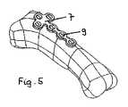
図4〜図7は、図2及び図3による複数の固定要素9を、基節骨基部骨折の治療用の骨プレート7と組み合わせて含む、組立体の例示的な実施形態の使用を示している。骨プレート7は、雌ねじ12を備えた数個のプレート穴8を有しており、図4に示されるように、固定要素9はそれぞれこの雌ねじ12に挿入され得る。 4-7 illustrate the use of an exemplary embodiment of an assembly comprising a plurality of
一般に、手の骨折は、図4に示されるように真っ直ぐ又はT字形のいずれかである骨プレート7で治療され、該骨プレート7は、骨ねじで指節骨又は中手骨上に固定されて良好な安定性をもたらす。本発明の実施形態によると、骨プレート7は、固定要素9(例えば、図2及び図3による鋲)を使用して、骨に取り付けられることができる。いくつかの実施形態では、固定要素9はPMMAで製造されており、それらの前側11は、重合性及び/又は架橋性材料の層3でコーティングされている。骨膜の除去及び本明細書に記載される層3の活性化の後、固定要素9はプレート穴8に螺入され、固定要素9の前側11が骨表面と当接するまで進められる。いくつかの実施形態では、固定要素9の表面及びプレート穴8の表面の少なくとも一部は、例えば、フックとアイレットの形態の連動手段を備えている。いくつかの実施形態では、固定要素9は、図7に示すようにプレート穴8に完全に螺入されると、各固定要素の後端部19が骨プレート7の上面と実質的に同一面になるように、サイズ設定及び寸法設定される。いくつかの実施形態では、固定要素9は、骨の表面と接触するが、該表面を貫通しない。いくつかの実施形態では、固定要素9は、骨の皮層に侵入しない。いくつかの実施形態では、固定要素9は骨に侵入するが、骨の皮層を越えて侵入することはない。 In general, a hand fracture is treated with a
図5及び図6は、基節骨の表面に接着された固定要素9を用いて基節骨に固定された骨プレート7を示している。 5 and 6 show the
図8は、各固定要素9がキャップ13を用いてプレート穴8の中に係止されている、組立体の別の実施形態を示している。いくつかの実施形態では、キャップ13は、固定要素9の上面を少なくとも部分的に覆うように構成されている。いくつかの実施形態では、キャップ13は、プレート穴8の中の固定要素9の上に螺入するように構成される。いくつかの実施形態では、キャップ13は、固定要素9が穴8から抜け出るのを防止するように構成される。いくつかの実施形態では、キャップ13は、軟組織が穴8内に内部成長するのを防止するように構成される。いくつかの実施形態では、キャップ13は、キャップ13を骨プレート7の中にねじ込む又は駆動するためのツールを受容するように構成される。いくつかの実施形態では、キャップ13の表面は、ツールを受容するための空洞を画定する。 FIG. 8 shows another embodiment of the assembly in which each fixing
ここで図9を参照すると、いくつかの実施形態では、本発明の方法は、最初に固定要素9を骨21の表面に固定することを含む。いくつかの実施形態では、固定要素9は、本明細書に記載されているように活性化される重合性及び/又は架橋性材料の層でコーティングされており、かつ固定要素9を骨21に固定するために骨21の表面と接触する前端部を含む。例えば、いくつかの実施形態では、重合性及び/又は架橋性材料の層は、電磁エネルギー、光、又は水分に暴露されることによって活性化された後、骨21の表面に押し付けられる。図1〜図3の実施形態と同様に、重合性及び/又は架橋性材料の層は、活性化の前に除去される取り外し可能なカバーシートによって保護され得る。 Referring now to FIG. 9, in some embodiments, the method of the present invention includes first securing the
固定要素9を骨21の表面に固定した後、骨プレート7が固定要素9に連結されてもよい。いくつかの実施形態では、骨プレート7は、固定要素9を骨21に固定した状態で、固定要素9を骨プレート7の穴8に受容するように骨プレート7を位置決めすることによって、固定要素9に連結される。いくつかの実施形態では、固定要素9は、締まり嵌め、摩擦嵌め、又はスナップ嵌めによって骨プレート7(例えば、穴8の内部)に連結及び固定される。他の実施形態では、穴8は雌ねじを備えており、固定要素9は骨プレート7の穴8にねじ込まれるように構成される。 After fixing the fixing
更なる実施形態では、本明細書に記載されるキャップ13は、固定要素9の露出端(例えば、後端部)を覆うために、穴8の上に設けられてもよい。いくつかの実施形態によるキャップ13は、軟組織が穴8内に内部成長するのを防止するように構成され得る。いくつかの実施形態では、キャップ13は、骨プレート7が固定要素9に連結された後に、骨プレート7に固定される。いくつかの実施形態では、キャップ13は、骨プレート7の穴8にねじ込まれるように構成されたねじ切りされた部分13aと、穴8の直径より大きい直径を有する上部13bとを含む。他の実施形態では、キャップ13は、締まり嵌め、摩擦嵌め、又はスナップ嵌めによって、骨プレート7の穴8の中に固定されてもよい。 In further embodiments, the
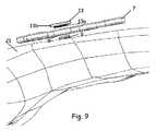
図10は、骨片21a;21bを整復する場合のインプラント1の使用の更なる例を示している。この例によるインプラント1は、ピン17として構成されている。各ピン17は、骨片21a;21bに固定されている。ピン17は、例えば、2つのピン17の一方又はそれぞれの後部に整復鉗子を位置付けることができるように寸法設定された長さLを有している。いくつかの実施形態では、ピン17は、少なくとも40mmの長さLを有する。いくつかの実施形態では、ピン17は、約45mm〜約50mmの最小長を有する。いくつかの実施形態では、ピン17は、約100mm〜約110mmの最大長を有する。 FIG. 10 shows a further example of the use of the
ピン17は、長手方向軸23と、前側11を備えた前端部18と、後端部19と、いくつかの実施形態では、剛性材料で製造され、かつ本明細書に記載のような重合性及び/又は架橋性材料の層3を備えている部分2とを含む。部分2は、上記重合性及び/又は架橋性材料の層3がピン17の前側11に位置するように、ピン17の後端部19から前端部18まで延在し得る。上記ピン17が人体又は動物体に植え込まれると、上記層3は骨の表面と接触することができる。いくつかの実施形態では、ピン17は、骨の表面と接触するが、該表面を貫通しない。いくつかの実施形態では、ピン17は、骨の皮層に侵入しない。いくつかの実施形態では、ピン17は、骨に侵入するが、骨の皮層を越えて侵入することはない。 The
いくつかの実施形態では、ピン17は、生体適合性でかつ生体安定性のポリマーで製造され得、好ましくはポリエーテルエーテルケトン(PEEK)又はPMMAで製造され得る。層3は、重合性及び/又は架橋性材料、好ましくはMMAと、可視光又は紫外線に反応する触媒とで作製され得る。あるいは、重合性及び/又は架橋性材料の層3は、重合性及び/又は架橋性材料の層3が水分で活性化され得るように、水分によって活性化されてポリウレタンとなるイソシアネートで作製され得る。 In some embodiments, the
図1〜図3の実施形態と同様に、層3は取り外し可能なカバーシートで保護されることができ、インプラント1一式は、無菌パック内に封入されることができる。使用する際、ピン17は無菌パック5から取り出され、存在する場合、カバーシートは除去される。ピン17は、続いて、重合性及び/又は架橋性材料の層3が取り付けられているピン17の前側11が骨と接触するまで、軟組織に押し込まれる。 Similar to the embodiment of FIGS. 1-3, the
いくつかの実施形態では、重合性及び/又は架橋性材料の層3は、軟組織に挿入される直前に活性化され得、活性化された層3を備えるピン17は、重合性及び/又は架橋性材料の層3が取り付けられているピン17の前側11が骨と接触するまで、軟組織に押し込まれる。いくつかの実施形態では、層3は、光によって活性化される重合性及び/又は架橋性材料を含み、軟組織に挿入される直前に光に暴露することによって活性され得る。代替的な実施形態では、層3は、水分によって活性化される重合性及び/又は架橋性材料(例えば、水分によって活性化されてポリウレタンとなるイソシアネート)を含み、軟組織に挿入される直前に水分で活性化され得る。 In some embodiments, the
更に図10に示すように、いくつかの実施形態によると、伸延具、若しくは牽引器具、又は創外固定器の形態の整復器具14を、2つのピン17に取り付けることができる。いくつかの実施形態では、整復器具14は、それぞれ整復器具14をピン17に連結するための、ねじ切りされたコネクトロッド15と締め付け装置16とを備え得る。ねじ切りされたコネクトロッド15と横方向に螺合しているナット22は、骨片21a;21bを互いに向けて押すように構成されている。第2のナットは、必要な場合に2つの骨片21a;21bを伸延させることができるように、2つのピン17の間のねじ切りされたコネクトロッド15と螺合している。あるいは、他の実施形態では、骨折を手動で整復するために、T型ハンドルを備えた自在チャックが各ピン17に固定され得る。いくつかの実施形態では、骨片21a;21bを整復した後、整復器具14を除去することができ、又は創外固定器をピン17に固定することができる。 As further shown in FIG. 10, according to some embodiments, a
骨折が完治した後、層3と骨表面との間の結合を切断するのに十分な機械的力により、いくつかの実施形態による骨表面からピン17を取り外すことができる。いくつかの実施形態では、ピン17が取り付けられていた場所の骨表面を洗浄して、あらゆる残留ポリマー物質を除去することができる。いくつかの実施形態では、ピン17は骨の表面に侵入しなかったので、ピン17を取り外しても骨に空洞が残らない。 After the fracture is completely healed, the
以上、本発明及びその利点について詳細に説明したが、付属の特許請求の範囲によって定義される本発明の趣旨及び範囲から逸脱することなく様々な変更、置換、及び改変を行いうる点は理解されるはずである。更に、本願の範囲は、本明細書に記載したプロセス、機械、製造法、物質組成、手段、方法、及び工程の特定の実施形態に限定されることを意図するものではない。当業者であれば本発明の開示内容から直ちに認識されるように、本明細書に述べられる対応する実施例と実質的に同じ機能を行うか又は実質的に同じ結果を実現する既存の、又は将来的に開発されるプロセス、機械、製造、物質の組成、手段、方法、及び工程を本発明に基づいて利用することが可能である。 While the invention and its advantages have been described in detail above, it will be understood that various changes, substitutions and modifications can be made without departing from the spirit and scope of the invention as defined by the appended claims. Should be. Furthermore, the scope of the present application is not intended to be limited to the specific embodiments of the processes, machines, manufacturing methods, material compositions, means, methods, and steps described herein. Those skilled in the art will immediately recognize from the disclosure of the present invention that an existing or performs substantially the same function or achieves substantially the same result as the corresponding embodiments described herein, or Future-developed processes, machines, manufacturing, material compositions, means, methods, and steps can be utilized in accordance with the present invention.
本発明の様々な変更及び改造が特許請求の範囲の広範な範囲を逸脱することなくなし得ることが、当業者によって理解されるであろう。これらのいくつかは上述されており、他は当業者に明らかであろう。 It will be appreciated by persons skilled in the art that various modifications and alterations of the present invention can be made without departing from the broad scope of the appended claims. Some of these are described above and others will be apparent to those skilled in the art.
〔実施の態様〕
(1) 患者に植え込むためのインプラントにおいて、
前記インプラントを操作するための後端部と、
骨表面と接触するように構成された前端部であって、該前端部は、重合性及び/又は架橋性材料の未硬化層を備える、前端部と、
前記前端部に隣接する、透明ポリマーで作製された部分と、を含むインプラント。
(2) 前記未硬化層が、重合性両親媒性モノマーを含む、実施態様1に記載のインプラント。
(3) 前記両親媒性モノマーが、分岐状若しくは直鎖状の、置換若しくは無置換の、飽和若しくは部分的に不飽和の、C10〜C30のアルキル−、アルケニル−、アルキルアリール−、アリール−、シクロアルキル−、アルキルシクロアルキル、アルキルシクロアリール−カルボン酸塩、−リン酸塩、又は−硫酸塩、及びこれらの混合物からなる群から選択される成分を含む、実施態様2に記載のインプラント。
(4) 前記両親媒性モノマーが、無置換の直鎖状C10〜C20のアルキルカルボン酸塩若しくはアルキル硫酸塩、又はそれらのアルカリ塩若しくはアルカリ土類塩それぞれ、及びこれらの混合物からなる群から選択される少なくとも1つの成分を含み、アルカリ塩又はアルカリ土類塩としては好ましくは、ラウリン酸塩、ステアリン酸塩、パルミチン酸塩、ミリスチン酸塩、オレイン酸塩、ベヘン酸塩、ドデシル硫酸塩である、実施態様2に記載のインプラント。
(5) 前記インプラントが無菌パック内に封入される、実施態様1〜4のいずれかに記載のインプラント。Embodiment
(1) In an implant for implantation in a patient,
A rear end for manipulating the implant;
A front end configured to contact a bone surface, the front end comprising an uncured layer of a polymerizable and / or crosslinkable material;
An implant comprising a portion made of a transparent polymer adjacent to the front end.
(2) The implant according to
(3) the amphiphilic monomer is a branched or straight chain, substituted or unsubstituted, saturated or partially unsaturated, alkyl of C10 -C30 -, alkenyl -, alkyl aryl -, aryl The implant of
(4) The amphiphilic monomer is a group consisting of an unsubstituted linear C10 to C20 alkyl carboxylate or alkyl sulfate, or an alkali salt or alkaline earth salt thereof, and a mixture thereof. The alkali salt or alkaline earth salt is preferably laurate, stearate, palmitate, myristate, oleate, behenate, dodecyl sulfate. The implant of
(5) The implant according to any one of
(6) 前記重合性及び/又は架橋性材料が、ポリウレタンを形成することができる、水分によって活性化されるイソシアネートである、実施態様1〜5のいずれかに記載のインプラント。
(7) 前記インプラントが、鋲、ピン、ねじ、又はボルトとして構成される、実施態様1〜6のいずれかに記載のインプラント。
(8) 前記インプラントが、45mm〜50mmの最小長を有するピンとして構成され、かつ、整復器具に取り付けられるように構成される、実施態様1〜7のいずれかに記載のインプラント。
(9) 前記インプラントが、100mm〜110mmの最大長を有するピンとして構成される、実施態様7に記載のインプラント。
(10) 前記未硬化層が、取り外し可能なカバーによって保護される、実施態様1〜9のいずれかに記載のインプラント。(6) The implant according to any of embodiments 1-5, wherein the polymerizable and / or crosslinkable material is a moisture activated isocyanate capable of forming a polyurethane.
(7) The implant according to any one of
(8) The implant according to any of embodiments 1-7, wherein the implant is configured as a pin having a minimum length of 45 mm to 50 mm and is configured to be attached to a reduction device.
(9) The implant of
(10) The implant according to any of embodiments 1-9, wherein the uncured layer is protected by a removable cover.
(11) 前記透明ポリマー部分が、紫外線照射に対して透明である、実施態様1〜10のいずれかに記載のインプラント。
(12) 前記未硬化層が、エポキシ樹脂、フィブリン接着剤、ポリウレタン、及びこれらの組み合わせの群から選択される材料を含む、実施態様1〜11のいずれかに記載のインプラント。
(13) 前記未硬化層が、100nm〜1000μmの厚さを有する、実施態様1〜12のいずれかに記載のインプラント。
(14) 前記透明ポリマー部分が、ポリエーテルエーテルケトン又はポリ(メチルメタクリレート)で作製される、実施態様1〜13のいずれかに記載のインプラント。
(15) 前記透明ポリマー部分が剛性である、実施態様1〜14のいずれかに記載のインプラント。(11) The implant according to any one of
(12) The implant according to any of embodiments 1-11, wherein the uncured layer comprises a material selected from the group of epoxy resins, fibrin adhesives, polyurethanes, and combinations thereof.
(13) The implant according to any one of
(14) The implant according to any of embodiments 1-13, wherein the transparent polymer portion is made of polyetheretherketone or poly (methyl methacrylate).
(15) The implant according to any of embodiments 1-14, wherein the transparent polymer portion is rigid.
(16) 前記重合性及び/又は架橋性材料がシアノアクリレートである、実施態様1〜15のいずれかに記載のインプラント。
(17) 前記インプラントが、骨と接触するように構成された下面に、前記重合性及び/又は架橋性材料の層を含む、骨プレートである、実施態様1〜6又は10〜16のいずれかに記載のインプラント。
(18) 前記透明ポリマー部分に縫合糸を更に含む、実施態様1〜17のいずれかに記載のインプラント。
(19) 実施態様1〜7又は10〜16のいずれかに記載のインプラントと、
複数のプレート穴を備える骨プレートと、を備える組立体であって、前記インプラントが、前記後端部に位置する後側と、1つ又は2つ以上の側面と、前記プレート穴の1つに挿入するための、前記前端部に位置する前側であって、前記重合性及び/又は架橋性材料の未硬化層を備える前側と、を有する固定要素である、組立体。
(20) 前記側面が、少なくとも一部が前記重合性及び/又は架橋性材料の層を備える、実施態様19に記載の組立体。(16) The implant according to any one of
(17) Any of embodiments 1-6 or 10-16, wherein the implant is a bone plate comprising a layer of the polymerizable and / or crosslinkable material on a lower surface configured to contact bone. The implant according to 1.
(18) The implant according to any one of
(19) The implant according to any one of
A bone plate comprising a plurality of plate holes, wherein the implant is located on the posterior side located at the posterior end, one or more side surfaces, and one of the plate holes. An assembly that is a fastening element having a front side for insertion, the front side being located at the front end and comprising an uncured layer of the polymerizable and / or crosslinkable material.
20. The assembly of
(21) 前記固定要素の前記表面及び前記プレート穴の少なくとも一部が、連動手段を備える、実施態様19又は20に記載の組立体。
(22) 骨の上に位置付けられ、かつ少なくとも1つのプレート穴を有する骨プレートの固定方法において、
前端部と、後端部と、取り外し可能なカバーシートによって保護される、前記前端部に位置する重合性及び/又は架橋性材料の層と、を含む固定インプラントを提供することと、
前記取り外し可能なカバーシートを前記固定インプラントから除去することと、
前記重合性及び/又は架橋性材料を、電磁エネルギー又は水分で活性化させることと、
前記固定インプラントを、骨の上に位置付けられた前記骨プレートの前記少なくとも1つのプレート穴に挿入することと、
前記前端部の前記活性化された層を、前記骨の表面を貫通することなく前記骨の該表面と接触させるために、前記固定インプラントの前記後端部に圧力を印加することと、
前記活性化及び加圧された層を重合及び/又は架橋させて、前記骨に接着させることと、を含む方法。
(23) 前記固定インプラントが、前記前端部に隣接する、透明ポリマーで作製された部分を含み、前記重合性及び/又は架橋性材料の活性化が、前記固定インプラントを、前記骨プレートの前記少なくとも1つのプレート穴に挿入した後に生じ、前記重合性及び/又は架橋性材料の活性化が、前記透明ポリマーで作製された部分を通じて電磁エネルギーを伝達することを含む、実施態様22に記載の方法。
(24) 前記固定インプラントの前記前端部の前記活性化された層が前記骨に押し付けられる場所の、前記骨の骨膜を除去することを更に含む、実施態様22又は23に記載の方法。
(25) 1つ又は2つ以上のピンを用いて骨片を整復する方法において、
A)各骨片の整復されるべき領域において切開を行う工程と、
B)前端部と、後端部と、前記前端部に位置する重合性及び/又は架橋性材料の未硬化層とを備えるピンを提供する工程と、
C)前記重合性及び/又は架橋性材料を電磁エネルギー又は水分で活性化する工程と、
D)前記ピンを前記切開に導入する工程と、
E)前記前端部の前記活性化された層を、前記骨片の表面を貫通することなく前記各骨片と接触させるために、前記後端部を押す工程と、
F)前記活性化及び加圧された層を重合又は架橋させて、前記骨片に接着させる工程と、
G)整復されるべき各骨片に対して工程B)〜F)を繰り返す工程と、
H)前記1つ又は2つ以上のピンを整復するための補助器具として使用することによって、骨折を整復する工程と、を含む方法。21. The assembly of
(22) In a method for fixing a bone plate positioned on a bone and having at least one plate hole,
Providing a fixation implant comprising a front end, a rear end, and a layer of polymerizable and / or crosslinkable material located at the front end, protected by a removable cover sheet;
Removing the removable cover sheet from the fixation implant;
Activating the polymerizable and / or crosslinkable material with electromagnetic energy or moisture;
Inserting the fixation implant into the at least one plate hole of the bone plate positioned over bone;
Applying pressure to the posterior end of the fixation implant to bring the activated layer of the anterior end into contact with the surface of the bone without penetrating the surface of the bone;
Polymerizing and / or crosslinking the activated and pressurized layer to adhere to the bone.
(23) The fixation implant includes a portion made of a transparent polymer adjacent to the front end, and activation of the polymerizable and / or cross-linkable material causes the fixation implant to become at least the bone plate. 23. The method of
24. The method of
(25) In a method of reducing a bone fragment using one or more pins,
A) making an incision in the area of each bone fragment to be reduced;
B) providing a pin comprising a front end, a rear end, and an uncured layer of a polymerizable and / or crosslinkable material located at the front end;
C) activating the polymerizable and / or crosslinkable material with electromagnetic energy or moisture;
D) introducing the pin into the incision;
E) pushing the back end to bring the activated layer of the front end into contact with each bone fragment without penetrating the surface of the bone fragment;
F) polymerizing or crosslinking the activated and pressurized layer to adhere to the bone fragment;
G) repeating steps B) to F) for each bone fragment to be reduced;
H) reducing the fracture by using the one or more pins as an auxiliary instrument to reduce.
(26) 骨プレートを骨に固定する方法において、
重合性及び/又は架橋性材料の層を備える前端部と、後端部とを含む固定要素を提供することと、
前記重合性及び/又は架橋性材料の層を活性化させることと、
前記重合性及び/又は架橋性材料の活性化された層を、骨の表面に接触させて、前記骨の表面を貫通することなく前記固定要素を前記骨の表面に固定することと、
前記固定要素が前記骨の表面に固定された後に、前記骨プレートを前記固定要素に連結することと、を含む方法。
(27) 前記重合性及び/又は架橋性材料の層を活性化させることが、前記層を電磁エネルギー、光、及び/又は水分に暴露することを含む、実施態様26に記載の方法。
(28) 前記骨プレートが、前記固定要素を受容するように構成及び寸法設定された穴を備え、前記骨プレートを前記固定要素に連結することが、前記穴の中に前記固定要素を受容するように前記骨プレートを位置決めすることを含む、実施態様26又は27に記載の方法。
(29) 前記骨プレートを前記固定要素に連結した後に、前記固定要素の前記後端部を覆うように構成されているキャップを前記穴に固定することを更に含む、実施態様28に記載の方法。
(30) 前記キャップが、前記キャップを前記穴に固定するために前記穴にねじ込まれるように構成された、ねじ切りされた部分を含む、実施態様29に記載の方法。(26) In a method of fixing a bone plate to bone,
Providing a fixation element comprising a front end comprising a layer of polymerizable and / or crosslinkable material and a rear end;
Activating the layer of polymerizable and / or crosslinkable material;
Contacting the activated layer of the polymerizable and / or crosslinkable material with the bone surface to secure the fixation element to the bone surface without penetrating the bone surface;
Connecting the bone plate to the fixation element after the fixation element is fixed to the surface of the bone.
27. The method of embodiment 26, wherein activating the layer of polymerizable and / or crosslinkable material comprises exposing the layer to electromagnetic energy, light, and / or moisture.
(28) the bone plate comprises a hole configured and dimensioned to receive the fixation element, and coupling the bone plate to the fixation element receives the fixation element in the hole; 28. The method of embodiment 26 or 27, comprising positioning the bone plate as follows.
29. The method of embodiment 28, further comprising securing a cap configured to cover the back end of the fixation element to the hole after connecting the bone plate to the fixation element. .
30. The method of embodiment 29, wherein the cap includes a threaded portion configured to be screwed into the hole to secure the cap in the hole.
(31) 前記キャップが、前記穴の直径より大きい直径を有する上部を含む、実施態様29又は30に記載の方法。
(32) 前記骨プレートが、締まり嵌め、摩擦嵌め、又はスナップ嵌めによって前記固定要素と連結される、実施態様26〜31のいずれかに記載の方法。31. The method of embodiment 29 or 30, wherein the cap includes an upper portion having a diameter that is greater than the diameter of the hole.
32. A method according to any of embodiments 26-31, wherein the bone plate is coupled to the fixation element by an interference fit, a friction fit, or a snap fit.
Claims (14)
Translated fromJapanese前記インプラントを操作するための後端部と、
前記骨プレートの複数のプレート穴を通して骨表面と接触するように構成された前端部であって、該前端部は、重合性及び/又は架橋性材料の未硬化層を備える、前端部と、
前記前端部に隣接する、剛性の透明ポリマーで作製された部分であって、前記部分を通じて、前記重合性及び/又は架橋性材料の層が活性化され得る、部分と、を含み、
前記部分は、前記インプラントの前記後端部から前記インプラントの前記前端部へと、可視光または紫外光を透過するように構成されており、
前記未硬化層が、エポキシ樹脂、フィブリン接着剤、ポリウレタン、及びこれらの組み合わせの群から選択される材料を含むインプラント。An implant for fixing a bone plate having a plurality of plate holes to a bone surface, wherein the implant is to be implanted in a patient.
A rear end for manipulating the implant;
A front end configured to contact a bone surface through a plurality of plate holes in the bone plate, the front end comprising an uncured layer of a polymerizable and / or crosslinkable material;
A portion made of a rigid transparent polymer adjacent to the front end, through which the layer of polymerizable and / or crosslinkable material can be activated,
The portion is configured to transmit visible or ultraviolet light from the back end of the implant to the front end of the implant;
An implantwherein the uncured layer comprises a material selected from the group of epoxy resins, fibrin adhesives, polyurethanes, and combinations thereof .
前記両親媒性モノマーが、無置換の直鎖状C10〜C20のアルキルカルボン酸塩若しくはアルキル硫酸塩、又はそれらのアルカリ塩若しくはアルカリ土類塩それぞれ、及びこれらの混合物からなる群から選択される少なくとも1つの成分を含む、請求項2に記載のインプラント。The amphiphilic monomer is a branched or straight chain, substituted or unsubstituted, saturated or partially unsaturated, alkyl of C10 -C30 -, alkenyl -, alkyl aryl -, aryl -, cyclo Comprises a component selected from the group consisting of alkyl-, alkylcycloalkyl, alkylcycloaryl-carboxylate, -phosphate, or -sulfate, and mixtures thereof, or
The amphiphilic monomer is an alkyl carboxylate or alkyl sulfate unsubstituted linear C10 -C20, or each their alkali salts or alkaline earth salts, and is selected from the group consisting of mixtures The implant of claim 2 comprising at least one component.
前記透明ポリマー部分が、剛性であり、かつ/又は、
前記透明ポリマー部分が、ポリエーテルエーテルケトン若しくはポリ(メチルメタクリレート)で作製される、請求項1〜7のいずれか一項に記載のインプラント。The transparent polymer portion is transparent to ultraviolet radiation and / or
The transparent polymer portion is rigid and / or
Implant according to any one of the preceding claims, wherein the transparent polymer part is made of polyetheretherketone or poly (methyl methacrylate).
複数のプレート穴を備える骨プレートと、を備える組立体であって、前記インプラントが、前記後端部に位置する後側と、1つ又は2つ以上の側面と、前記プレート穴の1つに挿入するための、前記前端部に位置する前側と、を有する固定要素であり、オプションとして、前記前側が、前記重合性及び/又は架橋性材料の未硬化層を備え、
前記側面が、少なくとも一部が前記重合性及び/又は架橋性材料の層を備え、かつ/あるいは、
前記固定要素の前記表面及び前記プレート穴の少なくとも一部が、連動手段を備える、組立体。The implant according to any one of claims 1 to 4 or 7 to10 ,
A bone plate comprising a plurality of plate holes, wherein the implant is located on the posterior side located at the posterior end, one or more side surfaces, and one of the plate holes. A fixing element having a front side located at the front end for insertion, and optionally, the front side comprises an uncured layer of the polymerizable and / or crosslinkable material;
The side surface comprises at least a layer of the polymerizable and / or crosslinkable material and / or
The assembly, wherein at least part of the surface of the fixing element and the plate hole comprises interlocking means.
オプションとして、前記インプラントが照射に暴露されるのを遮断するように構成された無菌パックと、を備える製品であって、
前記無菌パックは、可視光及び/又は紫外線に対して不透明な材料から製造される、製品。Implant according to any one of claims 1 to 12,
Optionally, a product comprising a sterile pack configured to block exposure of the implant to radiation,
The aseptic pack is manufactured from a material that is opaque to visible light and / or ultraviolet light.
Applications Claiming Priority (5)
| Application Number | Priority Date | Filing Date | Title |
|---|---|---|---|
| US201161527609P | 2011-08-25 | 2011-08-25 | |
| US61/527,609 | 2011-08-25 | ||
| US201261609913P | 2012-03-12 | 2012-03-12 | |
| US61/609,913 | 2012-03-12 | ||
| PCT/US2012/052213WO2013028951A1 (en) | 2011-08-25 | 2012-08-24 | Peek or pmma transparent implant comprising an adhesive layer of an uncured polymer. |
Publications (3)
| Publication Number | Publication Date |
|---|---|
| JP2014524346A JP2014524346A (en) | 2014-09-22 |
| JP2014524346A5 JP2014524346A5 (en) | 2015-08-13 |
| JP6147747B2true JP6147747B2 (en) | 2017-06-14 |
Family
ID=46763209
Family Applications (1)
| Application Number | Title | Priority Date | Filing Date |
|---|---|---|---|
| JP2014527321AExpired - Fee RelatedJP6147747B2 (en) | 2011-08-25 | 2012-08-24 | Transparent implant made of PEEK or PMMA with an uncured polymer adhesive layer |
Country Status (4)
| Country | Link |
|---|---|
| US (2) | US10111696B2 (en) |
| EP (1) | EP2747795B1 (en) |
| JP (1) | JP6147747B2 (en) |
| WO (1) | WO2013028951A1 (en) |
Families Citing this family (10)
| Publication number | Priority date | Publication date | Assignee | Title |
|---|---|---|---|---|
| JP6147747B2 (en) | 2011-08-25 | 2017-06-14 | シンセス・ゲーエムベーハーSynthes GmbH | Transparent implant made of PEEK or PMMA with an uncured polymer adhesive layer |
| JP2013226293A (en)* | 2012-04-26 | 2013-11-07 | Sun Medical Co Ltd | Material for bone fusion and kit therefrom |
| EP2879600A4 (en) | 2012-07-30 | 2016-03-30 | Sunnybrook Health Sciences Ct | OS STABILIZATION DEVICE AND METHOD FOR MANUFACTURING THE SAME |
| US10182855B2 (en)* | 2014-06-30 | 2019-01-22 | DePuy Synthes Products, Inc. | Phalangeal head plate |
| US9801670B2 (en)* | 2014-06-30 | 2017-10-31 | DePuy Synthes Products, Inc. | Locking first metacarpal plate |
| USD779065S1 (en) | 2014-10-08 | 2017-02-14 | Nuvasive, Inc. | Anterior cervical bone plate |
| CN105877831B (en)* | 2015-02-18 | 2020-09-25 | 比德尔曼技术有限责任两合公司 | Bone plate |
| US10912867B2 (en)* | 2017-11-15 | 2021-02-09 | De Novo Orthopedics Inc. | Bioinductive patch |
| JP7265849B2 (en)* | 2018-09-14 | 2023-04-27 | 京セラ株式会社 | Manufacturing method for medical components |
| US11643574B2 (en) | 2021-05-28 | 2023-05-09 | Cohesys Inc. | Adhesive devices and uses thereof |
Family Cites Families (59)
| Publication number | Priority date | Publication date | Assignee | Title |
|---|---|---|---|---|
| US4737143A (en)* | 1986-05-12 | 1988-04-12 | Russell David A | Catheter coupling and attachment assembly |
| DE8714635U1 (en)* | 1987-11-03 | 1987-12-17 | Waldemar Link Gmbh & Co, 2000 Hamburg | Hip joint cup prosthesis |
| US5163960A (en) | 1990-06-28 | 1992-11-17 | Bonutti Peter M | Surgical devices assembled using heat bondable materials |
| US5609648A (en)* | 1994-02-07 | 1997-03-11 | Sulzer Medizinaltechnik Ag | Acetabular cup assembly |
| GB9417288D0 (en) | 1994-08-25 | 1994-10-19 | Howmedica | Prosthetic bearing element and process for making such an element |
| US5520690A (en)* | 1995-04-13 | 1996-05-28 | Errico; Joseph P. | Anterior spinal polyaxial locking screw plate assembly |
| ES2297092T3 (en) | 1997-02-11 | 2008-05-01 | Warsaw Orthopedic, Inc. | PREVIOUS CERVICAL PLATE OF UNIQUE BLOCK. |
| US5925077A (en)* | 1997-04-02 | 1999-07-20 | Biomet, Inc. | Apparatus and method for plugging holes in an acetabular shell component |
| US20020128670A1 (en)* | 2000-11-22 | 2002-09-12 | Ulf Ulmsten | Surgical instrument and method for treating female urinary incontinence |
| US6692498B1 (en)* | 2000-11-27 | 2004-02-17 | Linvatec Corporation | Bioabsorbable, osteopromoting fixation plate |
| US6666870B2 (en)* | 2001-01-05 | 2003-12-23 | Robert A Dixon | Method utilizing chemical bonding to improve the bone screw fixation interface |
| JP4283665B2 (en)* | 2001-06-04 | 2009-06-24 | ウォーソー・オーソペディック・インコーポレーテッド | Dynamic plate for anterior cervical spine with movable segments |
| US7097645B2 (en)* | 2001-06-04 | 2006-08-29 | Sdgi Holdings, Inc. | Dynamic single-lock anterior cervical plate system having non-detachably fastened and moveable segments |
| US20030065397A1 (en)* | 2001-08-27 | 2003-04-03 | Hanssen Arlen D. | Prosthetic implant support structure |
| US6875427B1 (en) | 2001-10-09 | 2005-04-05 | Tissue Adhesive Technologies, Inc. | Light energized tissue adhesive |
| FR2831792B1 (en) | 2001-11-05 | 2004-07-16 | Jean Jacques Martin | EXTERNAL FIXER FOR IMMOBILIZING BONE FRAGMENTS, ESPECIALLY AT THE WRIST |
| US7713272B2 (en)* | 2001-12-20 | 2010-05-11 | Ethicon, Inc. | Bioabsorbable coatings of surgical devices |
| US20030181979A1 (en)* | 2002-01-23 | 2003-09-25 | Ferree Bret A. | Bone reinforcers |
| US7077843B2 (en)* | 2002-06-24 | 2006-07-18 | Lanx, Llc | Cervical plate |
| NL1021137C2 (en)* | 2002-07-23 | 2004-01-27 | Fondel Finance B V | Support element for attachment to bone. |
| ITTO20030034U1 (en)* | 2003-02-28 | 2004-09-01 | Vese Silvana | PLATE OF OSTEOSYNTHESIS |
| GB0305021D0 (en) | 2003-03-05 | 2003-04-09 | Howmedica Internat S De R L | Method for making a prosthetic bearing element |
| US20050107870A1 (en)* | 2003-04-08 | 2005-05-19 | Xingwu Wang | Medical device with multiple coating layers |
| US8298292B2 (en)* | 2003-04-16 | 2012-10-30 | Howmedica Osteonics Corp. | Craniofacial implant |
| US7931695B2 (en)* | 2003-07-15 | 2011-04-26 | Kensey Nash Corporation | Compliant osteosynthesis fixation plate |
| US20050033430A1 (en)* | 2003-08-05 | 2005-02-10 | Russell Powers | Surgical kit and method for providing sterilized equipment for use in spinal surgery |
| DE102004006501A1 (en)* | 2004-02-10 | 2005-09-01 | Charité-Universitätsmedizin Berlin | Component and method for assembling an implant assembly |
| US7887587B2 (en)* | 2004-06-04 | 2011-02-15 | Synthes Usa, Llc | Soft tissue spacer |
| US20060095138A1 (en) | 2004-06-09 | 2006-05-04 | Csaba Truckai | Composites and methods for treating bone |
| DE102004035546A1 (en)* | 2004-07-19 | 2006-02-16 | Wolter, Dietmar, Prof. Dr.Med. | Fixation system for bones and filling bodies for a bone fixation system |
| EP1771490B1 (en) | 2004-07-26 | 2019-01-02 | Synthes GmbH | Biocompatible, biodegradable polyurethane materials with controlled hydrophobic to hydrophilic ratio |
| CA2580101A1 (en)* | 2004-09-14 | 2006-03-23 | Spineco, Inc. | Implant device |
| CN103251449B (en)* | 2005-10-13 | 2016-03-02 | 斯恩蒂斯有限公司 | Drug-impregnated encasement |
| AU2007210055A1 (en)* | 2006-01-27 | 2007-08-09 | University Of Pittsburgh - Of The Commonwealth System Of Higher Education | Medical adhesive and methods of tissue adhesion |
| US8496657B2 (en) | 2006-02-07 | 2013-07-30 | P Tech, Llc. | Methods for utilizing vibratory energy to weld, stake and/or remove implants |
| FI119177B (en)* | 2006-05-05 | 2008-08-29 | Bioretec Oy | Bioabsorbable, deformable fixation material and implants |
| WO2008034135A2 (en)* | 2006-09-15 | 2008-03-20 | Pioneer Surgical Technology, Inc. | Joint arthroplasty devices having articulating members |
| US7842037B2 (en)* | 2006-09-27 | 2010-11-30 | Dupuy Products, Inc. | Flexible bone fixation device |
| US8758407B2 (en)* | 2006-12-21 | 2014-06-24 | Warsaw Orthopedic, Inc. | Methods for positioning a load-bearing orthopedic implant device in vivo |
| US8870871B2 (en)* | 2007-01-17 | 2014-10-28 | University Of Massachusetts Lowell | Biodegradable bone plates and bonding systems |
| KR101617051B1 (en) | 2007-09-17 | 2016-04-29 | 씨너지 바이오써지컬 아게 | medical implant |
| CA2718718A1 (en)* | 2008-03-21 | 2009-09-24 | Biomimedica, Inc | Methods, devices and compositions for adhering hydrated polymer implants to bone |
| US8226695B2 (en)* | 2008-10-10 | 2012-07-24 | K2M, Inc. | Occipital plate for cervical fixation |
| US20110015672A1 (en)* | 2009-07-17 | 2011-01-20 | Tyco Healthcare Group Lp | Method for Coating a Medical Device |
| US8529934B2 (en)* | 2009-08-21 | 2013-09-10 | Boston Scientific Scimed, Inc. | Crosslinkable polyisobutylene-based polymers and medical devices containing the same |
| US8808335B2 (en)* | 2010-03-08 | 2014-08-19 | Miami Device Solutions, Llc | Locking element for a polyaxial bone anchor, bone plate assembly and tool |
| EP2563250B1 (en)* | 2010-04-27 | 2017-11-15 | Synthes GmbH | Bone fixation system including k-wire compression |
| GB201011552D0 (en)* | 2010-07-09 | 2010-08-25 | Smith & Nephew | Adhesive and a method of delivery |
| US8882506B2 (en)* | 2010-08-17 | 2014-11-11 | Warsaw Orthopedic, Inc. | Implant repair system and method |
| US8672596B2 (en)* | 2011-03-10 | 2014-03-18 | Rohr, Inc. | System and method for attaching a stud to a surface |
| US8728082B2 (en)* | 2011-05-26 | 2014-05-20 | Biomet Manufacturing, Llc | Bone plate positioning scaffold |
| JP6147747B2 (en) | 2011-08-25 | 2017-06-14 | シンセス・ゲーエムベーハーSynthes GmbH | Transparent implant made of PEEK or PMMA with an uncured polymer adhesive layer |
| EP2793960B1 (en)* | 2011-12-22 | 2016-10-12 | 3M Innovative Properties Company | Adhesive article and method of making the same |
| US8778026B2 (en)* | 2012-03-09 | 2014-07-15 | Si-Bone Inc. | Artificial SI joint |
| DE102012206938B3 (en)* | 2012-04-26 | 2013-02-14 | Bayerische Motoren Werke Aktiengesellschaft | Method for connecting two components and component connection |
| US8801796B2 (en)* | 2012-12-31 | 2014-08-12 | Richard A. Rogachefsky | Bone prosthesis for maintaining joint operation in complex joints |
| US9283013B2 (en)* | 2013-03-14 | 2016-03-15 | Warsaw Orthopedic, Inc. | Filling systems for bone delivery devices |
| US9517097B2 (en)* | 2013-04-17 | 2016-12-13 | Stc.Unm | Low-profile, high tension mesh plate for subcutaneous fracture fixation |
| US20140376995A1 (en)* | 2013-06-20 | 2014-12-25 | Tesla Motors, Inc. | Air-tight Slip-on Structural Joint Not Using Sealant |
- 2012
- 2012-08-24JPJP2014527321Apatent/JP6147747B2/ennot_activeExpired - Fee Related
- 2012-08-24USUS13/593,966patent/US10111696B2/enactiveActive
- 2012-08-24EPEP12753652.2Apatent/EP2747795B1/enactiveActive
- 2012-08-24WOPCT/US2012/052213patent/WO2013028951A1/enactiveApplication Filing
- 2018
- 2018-10-22USUS16/166,896patent/US11179182B2/enactiveActive
Also Published As
| Publication number | Publication date |
|---|---|
| US11179182B2 (en) | 2021-11-23 |
| US20130053898A1 (en) | 2013-02-28 |
| WO2013028951A1 (en) | 2013-02-28 |
| EP2747795B1 (en) | 2017-11-15 |
| EP2747795A1 (en) | 2014-07-02 |
| US10111696B2 (en) | 2018-10-30 |
| US20190053839A1 (en) | 2019-02-21 |
| JP2014524346A (en) | 2014-09-22 |
Similar Documents
| Publication | Publication Date | Title |
|---|---|---|
| JP6147747B2 (en) | Transparent implant made of PEEK or PMMA with an uncured polymer adhesive layer | |
| JP5208988B2 (en) | Sonic screw | |
| US20190357949A1 (en) | Methods and devices for trauma welding | |
| US8672982B2 (en) | Apparatus and methods for repairing craniomaxillofacial bones using customized bone plates | |
| US8939977B2 (en) | Systems and methods for separating bone fixation devices from introducer | |
| US20170252077A1 (en) | Distal tip for bone fixation devices | |
| US8551124B2 (en) | Implantation pin, fixation device and method for implanting the implantation pin | |
| JP2004512090A (en) | Non-metallic implant device and method of assembling and securing intraoperatively | |
| BRPI1009207B1 (en) | spine stabilization device and parts kit to implant a spine stabilization device in a space between two vertebral bodies | |
| KR20140024239A (en) | Device for repairing a human or animal joint | |
| CN107296633A (en) | Suture holdfast and the method that suture is fixed for relative sclerous tissues | |
| JP2010188130A (en) | Method for repairing rotator cuff | |
| EP2465456B1 (en) | Implantation pin | |
| JP2021523753A (en) | Bone fixation implants and transplant methods |
Legal Events
| Date | Code | Title | Description |
|---|---|---|---|
| A521 | Request for written amendment filed | Free format text:JAPANESE INTERMEDIATE CODE: A523 Effective date:20150623 | |
| A621 | Written request for application examination | Free format text:JAPANESE INTERMEDIATE CODE: A621 Effective date:20150623 | |
| A131 | Notification of reasons for refusal | Free format text:JAPANESE INTERMEDIATE CODE: A131 Effective date:20160510 | |
| A521 | Request for written amendment filed | Free format text:JAPANESE INTERMEDIATE CODE: A523 Effective date:20160808 | |
| A02 | Decision of refusal | Free format text:JAPANESE INTERMEDIATE CODE: A02 Effective date:20161122 | |
| A521 | Request for written amendment filed | Free format text:JAPANESE INTERMEDIATE CODE: A523 Effective date:20170223 | |
| A911 | Transfer to examiner for re-examination before appeal (zenchi) | Free format text:JAPANESE INTERMEDIATE CODE: A911 Effective date:20170303 | |
| A131 | Notification of reasons for refusal | Free format text:JAPANESE INTERMEDIATE CODE: A131 Effective date:20170328 | |
| A521 | Request for written amendment filed | Free format text:JAPANESE INTERMEDIATE CODE: A523 Effective date:20170411 | |
| TRDD | Decision of grant or rejection written | ||
| A01 | Written decision to grant a patent or to grant a registration (utility model) | Free format text:JAPANESE INTERMEDIATE CODE: A01 Effective date:20170425 | |
| A61 | First payment of annual fees (during grant procedure) | Free format text:JAPANESE INTERMEDIATE CODE: A61 Effective date:20170517 | |
| R150 | Certificate of patent or registration of utility model | Ref document number:6147747 Country of ref document:JP Free format text:JAPANESE INTERMEDIATE CODE: R150 | |
| R250 | Receipt of annual fees | Free format text:JAPANESE INTERMEDIATE CODE: R250 | |
| R250 | Receipt of annual fees | Free format text:JAPANESE INTERMEDIATE CODE: R250 | |
| LAPS | Cancellation because of no payment of annual fees |