JP6147466B2 - Catheter with liquid-cooled control handle - Google Patents
Catheter with liquid-cooled control handleDownload PDFInfo
- Publication number
- JP6147466B2 JP6147466B2JP2011244181AJP2011244181AJP6147466B2JP 6147466 B2JP6147466 B2JP 6147466B2JP 2011244181 AJP2011244181 AJP 2011244181AJP 2011244181 AJP2011244181 AJP 2011244181AJP 6147466 B2JP6147466 B2JP 6147466B2
- Authority
- JP
- Japan
- Prior art keywords
- heat transfer
- catheter
- coolant
- heat
- transfer member
- Prior art date
- Legal status (The legal status is an assumption and is not a legal conclusion. Google has not performed a legal analysis and makes no representation as to the accuracy of the status listed.)
- Expired - Fee Related
Links
- 238000012546transferMethods0.000claimsdescription118
- 239000002826coolantSubstances0.000claimsdescription58
- 230000002262irrigationEffects0.000claimsdescription28
- 238000003973irrigationMethods0.000claimsdescription28
- 238000001816coolingMethods0.000claimsdescription17
- 230000007831electrophysiologyEffects0.000claimsdescription3
- 238000002001electrophysiologyMethods0.000claimsdescription3
- 239000012530fluidSubstances0.000description36
- 239000004020conductorSubstances0.000description14
- 230000032258transportEffects0.000description11
- 239000000463materialSubstances0.000description10
- 230000006835compressionEffects0.000description7
- 238000007906compressionMethods0.000description7
- WABPQHHGFIMREM-UHFFFAOYSA-Nlead(0)Chemical compound[Pb]WABPQHHGFIMREM-UHFFFAOYSA-N0.000description7
- 210000001519tissueAnatomy0.000description7
- 238000002679ablationMethods0.000description5
- 230000008878couplingEffects0.000description5
- 238000010168coupling processMethods0.000description5
- 238000005859coupling reactionMethods0.000description5
- 238000000034methodMethods0.000description5
- 229910001220stainless steelInorganic materials0.000description5
- 239000010935stainless steelSubstances0.000description5
- RYGMFSIKBFXOCR-UHFFFAOYSA-NCopperChemical compound[Cu]RYGMFSIKBFXOCR-UHFFFAOYSA-N0.000description4
- 229910052802copperInorganic materials0.000description4
- 239000010949copperSubstances0.000description4
- 230000000694effectsEffects0.000description4
- 230000033001locomotionEffects0.000description4
- 230000007246mechanismEffects0.000description4
- 239000002918waste heatSubstances0.000description4
- DNIAPMSPPWPWGF-UHFFFAOYSA-NPropylene glycolChemical compoundCC(O)CODNIAPMSPPWPWGF-UHFFFAOYSA-N0.000description3
- 239000000853adhesiveSubstances0.000description3
- 230000001070adhesive effectEffects0.000description3
- 229920002635polyurethanePolymers0.000description3
- 239000004814polyurethaneSubstances0.000description3
- 238000005476solderingMethods0.000description3
- 125000006850spacer groupChemical group0.000description3
- FAPWRFPIFSIZLT-UHFFFAOYSA-MSodium chlorideChemical compound[Na+].[Cl-]FAPWRFPIFSIZLT-UHFFFAOYSA-M0.000description2
- 239000004809TeflonSubstances0.000description2
- 229920006362Teflon®Polymers0.000description2
- 230000002159abnormal effectEffects0.000description2
- 230000003321amplificationEffects0.000description2
- 230000005540biological transmissionEffects0.000description2
- 210000004369bloodAnatomy0.000description2
- 239000008280bloodSubstances0.000description2
- 230000036760body temperatureEffects0.000description2
- 230000004087circulationEffects0.000description2
- 239000011248coating agentSubstances0.000description2
- 238000000576coating methodMethods0.000description2
- 210000005003heart tissueAnatomy0.000description2
- 238000001802infusionMethods0.000description2
- 238000003780insertionMethods0.000description2
- 230000037431insertionEffects0.000description2
- 238000013507mappingMethods0.000description2
- 229910052751metalInorganic materials0.000description2
- 239000002184metalSubstances0.000description2
- 238000003199nucleic acid amplification methodMethods0.000description2
- 230000037361pathwayEffects0.000description2
- 238000012545processingMethods0.000description2
- 239000011780sodium chlorideSubstances0.000description2
- 210000003813thumbAnatomy0.000description2
- 229920002614Polyether block amidePolymers0.000description1
- 239000004642PolyimideSubstances0.000description1
- 230000002411adverseEffects0.000description1
- 210000001367arteryAnatomy0.000description1
- 230000000712assemblyEffects0.000description1
- 238000000429assemblyMethods0.000description1
- 230000017531blood circulationEffects0.000description1
- 210000005242cardiac chamberAnatomy0.000description1
- 238000013153catheter ablationMethods0.000description1
- 230000008859changeEffects0.000description1
- 239000003795chemical substances by applicationSubstances0.000description1
- 238000004891communicationMethods0.000description1
- 230000008602contractionEffects0.000description1
- 238000010292electrical insulationMethods0.000description1
- 239000012777electrically insulating materialSubstances0.000description1
- 210000001105femoral arteryAnatomy0.000description1
- 238000010438heat treatmentMethods0.000description1
- 238000003384imaging methodMethods0.000description1
- 230000036512infertilityEffects0.000description1
- 238000012986modificationMethods0.000description1
- 230000004048modificationEffects0.000description1
- HLXZNVUGXRDIFK-UHFFFAOYSA-Nnickel titaniumChemical compound[Ti].[Ti].[Ti].[Ti].[Ti].[Ti].[Ti].[Ti].[Ti].[Ti].[Ti].[Ni].[Ni].[Ni].[Ni].[Ni].[Ni].[Ni].[Ni].[Ni].[Ni].[Ni].[Ni].[Ni].[Ni]HLXZNVUGXRDIFK-UHFFFAOYSA-N0.000description1
- 229910001000nickel titaniumInorganic materials0.000description1
- 229910000510noble metalInorganic materials0.000description1
- 231100000252nontoxicToxicity0.000description1
- 230000003000nontoxic effectEffects0.000description1
- 238000013021overheatingMethods0.000description1
- 230000002093peripheral effectEffects0.000description1
- 229920001721polyimidePolymers0.000description1
- 229920001296polysiloxanePolymers0.000description1
- 239000010970precious metalSubstances0.000description1
- 239000003507refrigerantSubstances0.000description1
- 230000003014reinforcing effectEffects0.000description1
- 238000004088simulationMethods0.000description1
- 230000001954sterilising effectEffects0.000description1
- 238000004659sterilization and disinfectionMethods0.000description1
- 238000006467substitution reactionMethods0.000description1
- 239000000758substrateSubstances0.000description1
- 210000003462veinAnatomy0.000description1
Images


Classifications
- A—HUMAN NECESSITIES
- A61—MEDICAL OR VETERINARY SCIENCE; HYGIENE
- A61B—DIAGNOSIS; SURGERY; IDENTIFICATION
- A61B18/00—Surgical instruments, devices or methods for transferring non-mechanical forms of energy to or from the body
- A61B18/04—Surgical instruments, devices or methods for transferring non-mechanical forms of energy to or from the body by heating
- A61B18/12—Surgical instruments, devices or methods for transferring non-mechanical forms of energy to or from the body by heating by passing a current through the tissue to be heated, e.g. high-frequency current
- A61B18/14—Probes or electrodes therefor
- A61B18/1492—Probes or electrodes therefor having a flexible, catheter-like structure, e.g. for heart ablation
- A—HUMAN NECESSITIES
- A61—MEDICAL OR VETERINARY SCIENCE; HYGIENE
- A61B—DIAGNOSIS; SURGERY; IDENTIFICATION
- A61B18/00—Surgical instruments, devices or methods for transferring non-mechanical forms of energy to or from the body
- A61B18/04—Surgical instruments, devices or methods for transferring non-mechanical forms of energy to or from the body by heating
- A61B18/12—Surgical instruments, devices or methods for transferring non-mechanical forms of energy to or from the body by heating by passing a current through the tissue to be heated, e.g. high-frequency current
- A—HUMAN NECESSITIES
- A61—MEDICAL OR VETERINARY SCIENCE; HYGIENE
- A61B—DIAGNOSIS; SURGERY; IDENTIFICATION
- A61B18/00—Surgical instruments, devices or methods for transferring non-mechanical forms of energy to or from the body
- A61B2018/00005—Cooling or heating of the probe or tissue immediately surrounding the probe
- A61B2018/00011—Cooling or heating of the probe or tissue immediately surrounding the probe with fluids
- A61B2018/00023—Cooling or heating of the probe or tissue immediately surrounding the probe with fluids closed, i.e. without wound contact by the fluid
- A—HUMAN NECESSITIES
- A61—MEDICAL OR VETERINARY SCIENCE; HYGIENE
- A61B—DIAGNOSIS; SURGERY; IDENTIFICATION
- A61B18/00—Surgical instruments, devices or methods for transferring non-mechanical forms of energy to or from the body
- A61B2018/00315—Surgical instruments, devices or methods for transferring non-mechanical forms of energy to or from the body for treatment of particular body parts
- A61B2018/00345—Vascular system
- A61B2018/00351—Heart
- A—HUMAN NECESSITIES
- A61—MEDICAL OR VETERINARY SCIENCE; HYGIENE
- A61B—DIAGNOSIS; SURGERY; IDENTIFICATION
- A61B18/00—Surgical instruments, devices or methods for transferring non-mechanical forms of energy to or from the body
- A61B2018/00571—Surgical instruments, devices or methods for transferring non-mechanical forms of energy to or from the body for achieving a particular surgical effect
- A61B2018/00577—Ablation
- A—HUMAN NECESSITIES
- A61—MEDICAL OR VETERINARY SCIENCE; HYGIENE
- A61B—DIAGNOSIS; SURGERY; IDENTIFICATION
- A61B18/00—Surgical instruments, devices or methods for transferring non-mechanical forms of energy to or from the body
- A61B2018/0091—Handpieces of the surgical instrument or device
Landscapes
- Health & Medical Sciences (AREA)
- Surgery (AREA)
- Engineering & Computer Science (AREA)
- Life Sciences & Earth Sciences (AREA)
- Medical Informatics (AREA)
- Molecular Biology (AREA)
- Nuclear Medicine, Radiotherapy & Molecular Imaging (AREA)
- Plasma & Fusion (AREA)
- Biomedical Technology (AREA)
- Heart & Thoracic Surgery (AREA)
- Physics & Mathematics (AREA)
- Otolaryngology (AREA)
- Animal Behavior & Ethology (AREA)
- General Health & Medical Sciences (AREA)
- Public Health (AREA)
- Veterinary Medicine (AREA)
- Cardiology (AREA)
- Media Introduction/Drainage Providing Device (AREA)
- Surgical Instruments (AREA)
- Thermotherapy And Cooling Therapy Devices (AREA)
Description
Translated fromJapanese本発明は、カテーテルに関し、詳細には改善された制御ハンドルを有するカテーテルに関する。 The present invention relates to a catheter, and more particularly to a catheter having an improved control handle.
カテーテルは医療業務において多年にわたり一般に用いられている。カテーテルの用途には、心臓における電気活動のシミュレーション及びマッピング、並びに異常な電気活動の部位の除去が挙げられる。そのようなカテーテルはまた、電極カテーテルと呼ばれる。使用時には、電極カテーテルは、主要な静脈若しくは動脈(例えば大腿動脈)に挿入され、次いで、身体内の対象の場所(例えば、心臓内の異常な電気活動がある心室)に案内される。 Catheters have been commonly used for many years in medical practice. Catheter applications include simulation and mapping of electrical activity in the heart, and removal of sites of abnormal electrical activity. Such a catheter is also called an electrode catheter. In use, an electrode catheter is inserted into a main vein or artery (eg, a femoral artery) and then guided to a location of interest within the body (eg, a ventricle with abnormal electrical activity within the heart).
典型的なアブレーション処置は、遠位端に先端電極を有するカテーテルの心腔内への挿入を必要とする。基準電極が患者の皮膚に提供され、一般にテープで留められる。RF(高周波)電流を先端電極に通電すると、先端電極の周囲の媒質(すなわち、血液及び組織)に、基準電極に向かって電流が流れる。電流の分布は、組織よりも導電性が高い血液に対する、組織と接触した電極表面の量によって決まる。組織の電気抵抗によって組織の加熱が発生する。組織が十分に加熱されると心組織の細胞が破壊され、心臓組織内に非導電性の損傷部位が形成される。そのような心臓アブレーション処置によって生成された損傷は、心臓内の誤った電気経路を効果的に中断する。 A typical ablation procedure requires the insertion of a catheter having a tip electrode at the distal end into the heart chamber. A reference electrode is provided on the patient's skin and is typically taped. When an RF (high frequency) current is passed through the tip electrode, the current flows through the medium around the tip electrode (ie, blood and tissue) toward the reference electrode. The distribution of current depends on the amount of electrode surface in contact with the tissue for blood that is more conductive than the tissue. Tissue heating occurs due to the electrical resistance of the tissue. When the tissue is heated sufficiently, the cells of the heart tissue are destroyed and a non-conductive damaged site is formed in the heart tissue. Damage generated by such cardiac ablation procedures effectively interrupts the wrong electrical pathway in the heart.
カテーテルは、典型的には、細長いカテーテル本体、カテーテル本体の遠位にある可撓性部分、及び可撓性部分の遠位にある先端部分を有する。典型的なアブレーションカテーテルは、炭化(charring)の回避と、より大きな損傷の要求と、を含む幾つかの理由のために、先端電極で灌注(irrigation)を提供する。血流によるより受動的な生理学的冷却の代わりに、アブレーション電極に室温の生理食塩水などを灌注することによって、アブレーション電極は積極的に冷却される。高周波電流の強さが、界面温度によって制限されなくなるので、電流を増やして損傷をより大きく球状にすることができる。 A catheter typically has an elongated catheter body, a flexible portion distal to the catheter body, and a tip portion distal to the flexible portion. A typical ablation catheter provides irrigation at the tip electrode for several reasons including avoidance of charring and the requirement for greater damage. Instead of more passive physiological cooling by blood flow, the ablation electrode is actively cooled by irrigating the ablation electrode with room temperature saline or the like. Since the strength of the high frequency current is no longer limited by the interface temperature, the current can be increased to make the damage larger and more spherical.
カテーテル本体の近位にある制御ハンドルは、主に、カテーテル内に延在する引込線に結合された撓み機構を収容して、ユーザが撓み機構を操作することができるインタフェースを提供する働きをする。灌注が提供された場合、灌注管は、制御ハンドル内を通って、流体を流体供給源からカテーテルの遠位端まで送る。また、制御ハンドルは、通常、例えば電磁位置センサからの信号の増幅及び/又は熱電対の電圧信号をデジタル化するデジタル化回路を含む、遠位部分又は先端電極との間の信号処理のように構成された様々な回路及びチップを支持するプリント回路基板を収容する。また、カテーテルが使用された後でカテーテル又は少なくとも電磁センサの再使用を防ぐために、回路基板を遮断するEPROMチップが含まれることがある。 A control handle proximal to the catheter body primarily serves to provide an interface that accommodates a deflection mechanism coupled to a lead wire extending into the catheter and allows a user to manipulate the deflection mechanism. If irrigation is provided, the irrigation tube passes fluid through the control handle from the fluid source to the distal end of the catheter. Also, the control handle typically includes signal processing with the distal portion or tip electrode, including, for example, signal amplification from an electromagnetic position sensor and / or digitization circuitry that digitizes the voltage signal of the thermocouple. Houses printed circuit boards that support the various configured circuits and chips. Also, an EPROM chip that shuts off the circuit board may be included to prevent reuse of the catheter or at least the electromagnetic sensor after the catheter is used.
PC基板を収容する制御ハンドルを備えた電流カテーテルは、PC基板の冷却をもたらすために、制御ハンドルの密室内の自然対流に依存する。カテーテルの性能と能力が高くなるにつれて、含まれる内部電子回路の数が増え、その結果、廃熱負荷が大きくなる。廃熱が増えると、その結果、制御ハンドル内の温度が高くなり、最終的にハンドル温度が高くなってユーザの快適さに悪影響を及ぼす可能性がある。 A current catheter with a control handle that houses the PC board relies on natural convection in the closed chamber of the control handle to provide cooling of the PC board. As the performance and capacity of the catheter increases, the number of internal electronic circuits involved increases, resulting in a greater waste heat load. As waste heat increases, the temperature in the control handle increases as a result, and eventually the handle temperature increases, which can adversely affect user comfort.
PC基板上には、PC基板の対流熱損失を高めるためにしばしば小さなファンが使用される。しかしながら、制御ハンドルは、典型的には密閉されているので、熱負荷はハンドル温度を高める。カテーテルハンドル内でファンが有効になるようにするには、カテーテルハンドルに入口及び出口格子又はポートを組み込まなければならない。しかし、そのような特徴は、ハンドルの審美性を低下させることがある。また、取り付けられた集積回路からの熱伝達を大きくするためにハンドルにヒートパイプを組む込むこともできるが、この場合も熱がハンドル内に残ってハンドル温度を上昇させる傾向がある。ヒートパイプのような自己ポンピング式微小流体熱交換器を使用してもよいが、そのような熱交換器は、ハンドル内に熱エネルギーを放射し、ハンドル温度を高めることになる。 On the PC board, a small fan is often used to increase the convective heat loss of the PC board. However, since the control handle is typically sealed, the heat load increases the handle temperature. In order for the fan to be effective within the catheter handle, the catheter handle must incorporate inlet and outlet grids or ports. However, such features can reduce the aesthetics of the handle. Also, a heat pipe can be incorporated into the handle to increase heat transfer from the attached integrated circuit, but in this case as well, heat remains in the handle and tends to increase the handle temperature. Self-pumped microfluidic heat exchangers such as heat pipes may be used, but such heat exchangers will radiate thermal energy into the handle and increase the handle temperature.
室温の灌注流体は、約20〜25℃(又は、68〜77°F)の範囲であり、これは、37℃(又は、98.6°F)の正常な体温よりかなり低く、灌注流体を制御ハンドルに通すことは知られているので、制御ハンドル内に流れる灌注流体を使用してPC基板を冷却し、制御ハンドルから熱を排出することによって、制御ハンドル内の温度を低くする改善された制御ハンドルを提供することが望ましい。そのように熱伝達を高めることによって、PC基板の動作温度が低下し、その結果、制御ハンドルが冷却される。 Room temperature irrigation fluid is in the range of about 20-25 ° C. (or 68-77 ° F.), which is significantly below normal body temperature of 37 ° C. (or 98.6 ° F.) Since it is known to pass through the control handle, the irrigation fluid flowing in the control handle is used to cool the PC board and drain heat away from the control handle, thereby reducing the temperature in the control handle. It is desirable to provide a control handle. By so increasing the heat transfer, the operating temperature of the PC board is lowered and, as a result, the control handle is cooled.
本発明は、改善された制御ハンドルを備えた患者の心臓内で使用されるように適応された電気生理学的カテーテルを対象とする。カテーテルは、典型的には、カテーテル本体と、プリント回路基板上に取り付けられた集積回路を含む熱源を収容する制御ハンドルとを有し、熱源は、制御ハンドル内に蓄積しユーザを不快にさせる、望ましくない廃熱負荷を作り出す可能性がある。本発明の特徴によれば、カテーテルは、制御ハンドル内の熱をより良好に放散するための熱伝達組立体を含む。熱伝達組立体は、ポンプ、冷却剤を収容するリザーバ、熱伝達部材、及び少なくともリザーバと熱伝達部材間で冷却剤を輸送する冷却剤輸送網を含む。一実施形態では、熱伝達部材は、制御ハンドル内に、集積回路から冷却剤に熱を伝達するために、冷却剤を収容する回路基板上の熱交換器として、配置される。別の実施形態では、制御ハンドル内の集積回路を内部的に冷却するために、集積回路を直接取り囲む少なくとも1つの熱伝達部材が回路基板上に配置される。第2の熱伝達部材は、熱交換器として制御ハンドルの外側に配置される。この実施形態の熱伝達部材は、IC熱伝達ユニット、カバー熱伝達ユニット又は熱伝達組立体でよい。実施形態は、閉じられた冷却剤輸送網で構成されてもよく、開かれた冷却剤輸送網で構成されてもよい。 The present invention is directed to an electrophysiology catheter adapted for use in a patient's heart with an improved control handle. The catheter typically has a catheter body and a control handle that houses a heat source that includes an integrated circuit mounted on a printed circuit board, which accumulates in the control handle and makes the user uncomfortable. May create undesirable waste heat load. In accordance with a feature of the present invention, the catheter includes a heat transfer assembly for better dissipating heat in the control handle. The heat transfer assembly includes a pump, a reservoir containing a coolant, a heat transfer member, and a coolant transport network that transports the coolant at least between the reservoir and the heat transfer member. In one embodiment, the heat transfer member is disposed in the control handle as a heat exchanger on a circuit board that contains the coolant to transfer heat from the integrated circuit to the coolant. In another embodiment, at least one heat transfer member that directly surrounds the integrated circuit is disposed on the circuit board to internally cool the integrated circuit in the control handle. The second heat transfer member is disposed outside the control handle as a heat exchanger. The heat transfer member of this embodiment may be an IC heat transfer unit, a cover heat transfer unit or a heat transfer assembly. Embodiments may consist of a closed coolant transport network or an open coolant transport network.
本発明の特徴及び態様は、添付図面と併せて以下の「発明を実施するための形態」から、より明らかになるであろう
本発明の実施形態は、以下において、詳述され、代表的な実施形態が示される。本開示は、しかしながら、多くの異なる形態で具体化されてもよく、以下に説明される代表的な実施形態に限定されるものと解釈されるものではない。ここで、第1要素が、第2要素に結合されている又は接続されていると記載されているとき、第1要素は、第2要素に直接接続されてもよく、又は1つ以上の第3要素を介して第2要素に間接的に接続されてもよい。 Embodiments of the present invention are described in detail below and representative embodiments are shown. The present disclosure, however, may be embodied in many different forms and should not be construed as limited to the exemplary embodiments set forth below. Here, when a first element is described as being coupled or connected to a second element, the first element may be directly connected to the second element, or one or more first elements It may be indirectly connected to the second element via three elements.
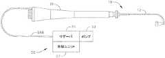
図1は、本発明の一実施形態によるカテーテル10を示す。カテーテル10は、近位端と遠位端を有する細長いカテーテルシャフト又は本体12と、カテーテルシャフト12の遠位にあり単方向又は双方向に撓む中間部分14と、中間部分の遠位端に先端電極17を有する先端部分15と、カテーテルシャフト12の近位端の制御ハンドル16と、を含む。有利には、カテーテルは、冷却剤のリザーバと、強制対流によって制御ハンドル内に収容された集積回路の冷却を提供するポンプと、を使用する熱伝達組立体を含む。 FIG. 1 shows a
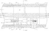
図2A及び2Bに示されるように、カテーテル本体12は、単一の軸又は中央ルーメン19を有する細長い管状の構造を備える。カテーテル本体12は可撓性、すなわち曲げることができるが、その長さに沿ってはほとんど圧縮することはできない。カテーテル本体12は任意の好適な構造のものでよく、任意の好適な材料で形成することができる。本発明における好ましい構造は、ポリウレタン又はPEBAXで形成された外壁20を含む。外壁20は、ステンレス鋼等の埋め込まれた編組メッシュを備え、カテーテル本体12のねじり剛性を上昇させ、その結果、制御ハンドル16が回転するとき、カテーテル10の中間部分14は対応する様式で回転することができる。 As shown in FIGS. 2A and 2B, the
カテーテル本体12の外径は重要ではないが、好ましくは約9フレンチ以下、より好ましくは約7フレンチである。同様に、外壁20の厚さもそれほど重要ではないが、外壁20は、中央ルーメン19が引込線、1つ以上のリード線、及び他の任意の所望の線、ケーブル又はチューブを収容できるように充分に薄い。必要に応じて、外壁20の内面は、ねじり安定性を向上させるために補強管21で裏打ちされる。一実施形態では、カテーテル10は、約0.229cm(0.090インチ)〜約0.239cm(0.094インチ)の外径と、約0.155cm(0.061インチ)〜約0.165cm(0.065インチ)の内径と、を有する外壁20を備える。 The outer diameter of the
中間部分14は、図2Cにも示されるような、複数のルーメンを有する管22の短い部分を備える。一実施形態では、第1のルーメン30は、1つ又は複数のリード線50と、先端電極17内の組織温度を監視する温度センサ(例えば、熱電対線43及び44)と、先端部分14に収容された電磁気位置75センサ用のケーブル74と、を支持する。第2のルーメン32は、平面内の少なくとも一方向に撓むように引込線を支持する。反対側にある第3のルーメン34は、平面内の第1の撓みの方向と反対の第2の方向の双方向の撓みが必要とされる場合に第2の引込線を支持することができる。第4ルーメン35は、先端電極に流体を供給するための灌注管61を有する。管22は、好ましくは、カテーテル本体12よりも可撓性である、好適な非毒性材料で作製される。一実施形態では、管22は、編組ポリウレタン、すなわち編組ステンレス鋼等の埋込みメッシュを有するポリウレタンである。ルーメンの数又は各ルーメンのサイズは、重要ではないが、実施形態により、リード線、引込線、電磁センサケーブル、熱電対線及び/又は灌注管路を収容するのに十分である。 The
カテーテル本体12を中間部分14に取り付ける好ましい手段が、図2A及び2Bに示されている。中間部分14の近位端は、カテーテル本体12の外壁20の内面を受容する外周ノッチ26を含む。中間部分14とカテーテル本体12とは、接着剤などによって取り付けられている。 A preferred means of attaching the
必要に応じて、カテーテル本体12内の、補剛管21の遠位端と中間部分14の近位端との間にスペーサ(図示せず)が入れられてもよい。スペーサは、カテーテル本体と中間部分との間の接点で可撓性に変化をもたらし、これにより、接点が折り畳まれる又はよじれることなく滑らかに曲がることが可能にする。そのようなスペーサを有するカテーテルが、その全開示内容を本願に援用する米国特許第5,964,757号に述べられている。 If necessary, a spacer (not shown) may be inserted in the
図3に示されたように、先端部分15は、先端電極17を含み、これは単一のルーメンコネクタ管23によって中間部分14の管22に接続されてもよい。コネクタ管は、電磁位置センサ75、及び管22から延びる様々な構成要素のための空間を提供し、先端電極17内に固定するために必要に応じて、様々な構成要素を方向付ける。その目的のために、先端電極の遠心面は、止まり孔が提供されている。開示された実施形態では、先端電極リード線40の遠位端を収容する止まり穴61、熱電対線43及び44の遠位端を収容する止まり穴63、及び電磁センサ75の遠位端を収容する止まり穴65が提供される。灌注経路66もまた、先端電極に形成され、灌注管61の遠位端を受容する。経路66は、横方向の分岐部67及び流体ポート69と連通し、流体が管61を通って送達され、先端電極の外側を通過するのを可能にする。 As shown in FIG. 3, the tip portion 15 includes a
図2Bに示されたように、引込線42は、中間部分14が一方向に撓むように提供される。米国特許第5,893,885号及び第6,066,125号に概略的に記載されているように、引込線42は、カテーテル本体12内に延在し、カテーテル本体12の近位端で制御ハンドル16に留められ、カテーテル本体12の遠位端で、Tバーアンカ71によって中間部分14の遠位端近くで管材料22に留められ、これらの開示全体は、参照により本明細書に組み込まれる。引込線は、ステンレス鋼やニチノールなどの任意の適切な金属で作製され、好ましくはテフロンRTMなどで被覆される。コーティングは、引込線42に潤滑性を付与する。プラーワイヤ42は好ましくは、約0.006〜0.025cm(0.010インチ)の範囲の直径を有する。 As shown in FIG. 2B, the lead-in
図2Bに示されたように、カテーテル本体12内に引込線42を取り囲む圧縮コイル72が配置される。圧縮コイル72は、カテーテル本体12の近位端から中間部分14の近位端まで延びている。圧縮コイルは、任意の適切な金属、好ましくはステンレス鋼で作製され、柔軟性を有し、即ち曲がることができかつ圧縮に耐えるようにきつく巻かれる。圧縮コイルの内径は、引っ張りワイアの直径よりもわずかに大きいことが好ましい。引込線上のテフロンRTMの被覆によって、引込線は圧縮コイル内で自由に摺動することができる。圧縮コイルの外表面は、例えば、ポリイミドチューブ材製等の可撓性の非導電性シース78によって被覆される。 As shown in FIG. 2B, a
カテーテル本体12に対する引込線42の長手方向の動きは、中間部分14の撓みを引き起こし、この動きは、制御ハンドル16の適切な操作によって行われる。本発明で使用するための好適な制御ハンドルの例は、米国特許第Re 34,502号、同第5,897,529号、及び同第7,377,906号に記載されており、これらの全開示は本明細書において参照として援用される。図4の実施形態では、制御ハンドル16の遠位端は、中間部分14を一方向に撓ませるための引込線42を操作する親指制御部56を有するピストン54を含むが、本発明が、双方向に撓ませるために2つの引込線を有する制御ハンドルに容易に適応できることを理解されたい。 Longitudinal movement of the
カテーテル本体12の近位端は、収縮スリーブ28によってピストン54に接続される。灌注管61、引込線42、リード線40、熱電対線43及び44、並びに電磁センサケーブル74は、カテーテル本体からピストン54を通って近位に延在する。引込線42は、ピストン54の近くに配置されたアンカーピン36に留められる。リード線40、熱電対線43及び44、並びに電磁センサケーブル74は、制御ハンドル16の側面の近くにある第1のトンネル58内に延在する。電磁センサケーブル74は、制御ハンドルの近位端内で回路基板64に接続される。電線73は、回路基板64を、例えばコンピュータとイメージングモニタ(図示せず)を含むマッピング及び/又はアブレーションシステムに接続する。 The proximal end of the
ピストン54内で、電磁センサケーブル74とリード線40は、伝達管27a内に配置され、引込線42は別の伝達管27b内に配置され、接着部53の近くの電線とケーブルの長手方向の動きが可能になる。灌注管61は、収縮スリーブ28内を近位方向に延在し、その近位端は、ピストン54のアンカーピン36と反対側近くにある第2のトンネル60内に延在する遠位導管68aを介して、熱伝達組立体50と連通する。 Within the piston 54, the
制御ハンドル16は、プリント回路(PC)基板64を含む熱源を収容し、プリント回路(PC)基板64上には、カテーテルの遠位部分に収容された電磁センサ及び/又は熱電対からの信号を含む信号の、局部的増幅及び/又は処理などの様々な機能を提供する複数の集積回路が取り付けられている。また、カテーテル又は少なくとも位置センサを単一使用に制限するために、EPROMチップが含まれてもよい。 The control handle 16 houses a heat source including a printed circuit (PC)
図の実施形態では、熱伝達組立体50は、リザーバ51とポンプ52(例えば、輸液ポンプ)、流体導管68a及び68bによる冷却剤輸送網、及び/又は典型的にはカテーテルによって流体を先端電極に送るために使用される他の機構及び構成要素を使用する開放系として構成される。前述のように、灌注流体は、カテーテル10の灌注管61内で送られる。本発明では、熱伝達組立体は、有利には、制御ハンドル内のPC基板を冷却する冷却剤として流体(例えば、灌注食塩水)を使用する。図1に示された実施形態では、輸液ポンプ52は、流体をリザーバ51から近位流体管68bを通して制御ハンドル16に送る。流体管68bの遠位端は、熱伝達ユニット、例えばPC基板64上の集積回路80、特に高出力集積回路上又はその近くに取り付けられた熱交換器90、の入口で終端しそこに流れ込む。熱交換器の出口は、ピストン54内の灌注管61の近位端と連通している遠位端を有する遠位流体管68aの近位端に流れ込む。図4に示されたように、遠位流体管68aは、接着部53によって制御ハンドル16の内部へ留められる。 In the illustrated embodiment, the
熱伝達組立体50は、強制対流の原理を利用して、PC基板64を冷却し、それにより制御ハンドル16を冷却する。カテーテルの使用中にPC基板上の集積回路80が加熱したとき、生成された熱は、熱交換器90に送られる。近位流体管68bによって輸送された灌注流体が熱交換器90内に流れるとき、熱交換器に伝達された熱は更に流体に伝達され、それにより熱交換器が冷却される。 The
当該技術分野で理解されているように、制御ハンドル内の開放空間と灌注流体との間の表面積を最大にし、同時に熱交換器90内に流れる流体の抵抗を最小にすることによって、PC基板64からの廃熱をリザーバ51からの灌注流体に放散するように構成される。熱交換器は、必要に応じてまた適宜、平行流、逆流、又は交差流を有する板状熱交換器又は管状熱交換器を含む任意の適切な形を取ることができる。熱交換器は、熱伝達が最適になるように熱伝導性がある任意の適切な材料で構成される。材料は、また、例えばステンレス鋼や貴金属めっき銅を含む、生物学的適合性でETO滅菌に適していなければならず、その結果、先端電極の出口から出て患者の体内に入るときに、灌注流体と熱交換器材料の接触によって流体の無菌性と生物学的適合性が損なわれることはない。 As understood in the art, the
灌注流体が、例えば約20〜25℃(又は、68〜77°F)の室温の場合、熱交換器90は、流体の温度を、約5度だけ、約25〜30℃又は(77〜86°F)まで上昇させると予想することができる。ヒトの正常な体温が約37℃(又は、98.6°F)なので、カテーテル処置の間に熱い流体を患者に導入する危険や患者を過熱する危険はほとんどない。しかしながら、必要に応じて、リザーバからの流体が制御ハンドルと熱交換器に入る前に流体を所定の温度だけ冷却する冷却ユニット57(例えば、ラジエータ、コンプレッサ、及び膨張弁を含む)によって流体の温度制御を行うことができ、それにより、流体が先端電極から患者の身体に入る前に、熱交換器及び/又は制御ハンドルから出る流体の温度が概略的に事前決定される。 If the irrigation fluid is at room temperature, for example, about 20-25 ° C. (or 68-77 ° F.), the heat exchanger 90 changes the temperature of the fluid by about 5 degrees, about 25-30 ° C. or (77-86 It can be expected to rise to ° F). Since the normal body temperature of a human is about 37 ° C. (or 98.6 ° F.), there is little risk of introducing hot fluid into the patient during the catheter procedure or overheating of the patient. However, if necessary, the temperature of the fluid may be reduced by a cooling unit 57 (including, for example, a radiator, compressor, and expansion valve) that cools the fluid to a predetermined temperature before the fluid from the reservoir enters the control handle and heat exchanger. Control can be provided, whereby the temperature of the fluid exiting the heat exchanger and / or control handle is generally pre-determined before fluid enters the patient's body from the tip electrode.
図5に示された代替実施形態では、熱伝達組立体50aは、閉鎖系として構成されており、冷媒は、PC基板64上に提供されたIC熱伝達ユニット100、200及び/又は250などの1つ又は複数の熱伝達ユニットと、冷却剤供給導管69bと冷却剤帰還導管69aを介して接続された遠隔熱交換器92との間の冷却剤輸送網によって再循環される。冷却剤で冷却された集積回路は、当該技術分野で既知であり、米国特許第7,400,502号及び第5,360,993号に記載されており、その全内容は、参照により本明細書に組み込まれる。図7aは、先行技術のコネクタ熱伝達ユニット(又は以下では、IC熱伝達ユニット)100の一実施形態を示し、この実施形態は、発熱構成要素101(集積回路又はチップなど)がコネクタ熱伝達ユニット100に挿入された状態で描かれる。IC熱伝達ユニット100は、様々な形状とサイズのものでよいが、これらは、主に、コネクタ熱伝達ユニットが結合される発熱構成要素とマザーボード(又は、PC基板)のサイズと導電体構成によって決定される。IC熱伝達ユニットの以下の実施形態は全て、IC熱伝達ユニットがどのタイプのマザーボードにも機械的に取り付けられていない用途で実施することができ、IC熱伝達ユニットは、マザーボードに任意の適切な方法で電気的に接続されてもよいことを理解されたい。IC熱伝達ユニットは、任意数の材料から成ってもよいが、軽量の電気絶縁材料が望ましい。 In the alternative embodiment shown in FIG. 5, the heat transfer assembly 50 a is configured as a closed system and the refrigerant is such as IC
図7aで、チップ101の導電体又はピン102が、レセプタクル104に挿入される。キャビティ103がIC熱伝達ユニット100内に配置され、その結果、キャビティの表面が、チップ101の表面に熱的に結合される。キャビティのこの表面は、発熱構成要素からキャビティ内を流れる冷却剤に熱を伝達するために、銅などの任意の高熱伝導性材料からなってもよい。熱伝達ユニット101は、キャビティに出入りする流体のための入口経路106と出口経路108を備えるように構成される。当業者によって理解されるように、必要に応じてキャビティと経路の構成を変化させて流体の流れ効率を変化させることができる。 In FIG. 7 a, the conductor or pin 102 of the
IC熱伝達ユニットピン109は、例えばはんだ付けによって、レセプタクル104をPC基板に電気的に接続する。チップ101のピンをPC基板に接続するために任意の適切な手段を使用することができ、IC熱伝達ユニットは、前述のレセプタクル104とピン109に限定されないことを理解されよう。例えば、コネクタ熱伝達ユニット100は、PC基板に挿入し、PC基板を通って、PC基板にはんだ付けするためにピン102を差し込む複数の孔を有してもよい。 The IC heat transfer unit pins 109 electrically connect the
発熱構成要素101に熱的に結合されたキャビティ103の表面が110として示される。表面110は、銅などの任意の高熱伝導性材料で構成されてもよい。この表面110は、高熱伝達特性を有するサーマルペーストによって、発熱構成要素101に結合されることが好ましい。あるいは、発熱構成要素101は、コネクタ熱伝達ユニット100内の適所に保持されてもよく、構成要素101から表面110への熱結合は、コネクタ熱伝達ユニット100から構成要素101への1つ又は複数のクリップ(図示せず)あるいは1つ又は複数のクランプ組立体(図示せず)を使用することにより達成されてもよい。いかなる場合も、最大の熱伝達を保証するために、構成要素と表面110の結合部にサーマルペーストを塗布することが好ましい。また、本発明は、構成要素101と表面110の間に積極的な力を作り出し、それにより熱伝導性を改善するために、締め付け力などを含む機械力の印加を含むがこれに限定されない、構成要素101を表面110に熱的に結合するための他の多くの可能性を包含することを理解されたい。 The surface of the
例えばマイクロプロセッサなどのほとんどの市販の発熱構成要素の導電体又はピン102は、典型的には、貴金属で被覆された銅である。したがって、そのような導電体又はピン102は、良好な導電体であることに加えて、良好な熱伝達体である。同様に、レセプタクル104と導電体又はピン109は両方とも、良好な導電特性と熱伝達特性を有する類似の材料で構成されてもよい。その場合、IC熱伝達ユニット100は、チップ101の冷却及び/又は追加の冷却を提供するために、良好な電気絶縁特性と熱伝達特性を有する材料で構成されもよい。この目的で、IC熱伝達ユニット100内で例えばハードシリコーンなどの様々な材料を使用することができる。具体的には、チップ101からの熱が、導電体又はピン102に伝達される。この熱の一部は、ピン102から、直接かつ/又はレセプタクル104とピン109を介して間接的に、例えばIC熱伝達ユニット100に伝達され、次にキャビティ103に伝達され、キャビティ内に流れる冷却剤が、その熱の一部又は全てを吸収し散逸する。IC熱伝達ユニット100の本体へ直接の最大熱伝達又は例えばレセプタクル104とピン109を介した間接の最大熱伝達を保証するために、導電体又はピン102にサーマルペーストが塗布される。また、ピン102とIC熱伝達ユニット100を、締め付ける動きで圧力を作り出す機械力の印加を含むがこれに限定されない他に手段によって熱的に結合することができることを理解されたい。 The conductors or pins 102 of most commercially available heat generating components, such as microprocessors, are typically copper coated with a noble metal. Accordingly, such a conductor or
表面チップ110を101に結合する更に別の代替において、表面110は開放されているか部分的に開放されていてもよく、それにより、冷却剤が、通常ICパック(図示せず)によって包まれ保護されたチップ101と直接接触することができ、それにより、表面110と、使用されるサーマルペースト又は他の熱接続媒体の両方の熱抵抗がなくなる。この状況で、例えば、表面110は、キャビティ103の周囲のフランジの形でもよい。フランジが、チップ101に結合され封止されたとき、キャビティが封止され、冷却剤は、漏れやこぼれなしにチップ101と直接接触することになる。 In yet another alternative for coupling the
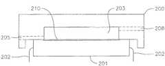
次に図7bを参照すると、チップ101の更なる冷却を提供するIC熱伝達ユニット100用のカバー熱伝達ユニット200が示される。カバー熱伝達ユニット200は、キャビティ203を含むIC熱伝達ユニット100と多くの類似点を有する。キャビティ203との間の冷却剤の出入りはそれぞれ、入口経路206と出口経路208によって提供される。チップ101の導電体又はピン202が示される。キャビティ203は、チップ101に熱的に結合された表面210を有する。 Referring now to FIG. 7b, a cover
可能なときには、熱伝達ユニット100及び200を、それぞれの入口がそれぞれの出口の下になるように向けることが望ましい。この向きによって、加熱された冷却剤が自然に上昇し、冷却された冷却剤が自然に下降するので、冷却システムが冷却剤の対流循環を利用することができる。このようにして、冷却剤の熱力学が、例えばポンプによる強制循環を支援し、電源が遮断された後でも発熱構成要素を更に冷却することができる。 When possible, it is desirable to orient the
カバー熱伝達ユニット200の機能は、チップ101の更に他の表面を冷却することである。図7cの実施形態に示されたように、単一チップを固定し冷却する熱伝達モジュール250を構成する際に、IC熱伝達ユニット100と共にカバー熱伝達ユニット200が使用されるとき、表面210はチップの一方の側から冷却剤に熱を伝達し、同時に表面110はチップの反対の側から冷却剤に熱を伝達する。この場合、カバー熱伝達ユニット200を使用することによって、IC熱伝達ユニット100と組み合わされたときに冷却能力又は性能を大幅に高めることができる。 The function of the cover
IC熱伝達ユニット220は、キャビティ223と、キャビティ223のチップ216に熱的に結合された表面230と、チップ216の導電体217を電気的に受け入れる複数のレセプタクル又は電気接点224と、レセプタクル224をPC基板に、例えば超音波はんだ付けによって電気的に接続する複数のピン又は導電体229と、を含む。 The IC
チップ216は、モジュール250内の適所に保持され、表面110及び210への構成要素の熱結合は、任意数の方法によって達成される。例えば、1つ又は複数の結合レセプタクル213に嵌め込まれた1つ又は複数のねじ212が利用されることがある。代替又は追加として、1つ又は複数のばねクリップ、又はIC熱伝達ユニット220からカバー200への締め付け力(図示せず)を作り出す様々な機械的締結具及び/又は接着剤のどれを利用してもよい。いずれにせよ、最大の熱伝達を保証するために、表面230の構成要素216との結合部と、表面210のチップ216と反対側への結合部とに、熱伝導材料を塗布することが好ましい。 The
表面230及び210をチップ216に結合する更に別の代替では、表面230及び210の一方又は両方が開放されているか又は部分的に開放されており、それにより冷却剤が、チップ216と直接接触することができ、それにより、表面230及び210両方の熱抵抗と、使用されるサーマルペースト又は他の熱接続媒体の熱抵抗がなくなる。この状況では、例えば、表面230及び210のいずれか又は両方は、それぞれキャビティ223及び203の周囲のフランジの形でよい。フランジが、発熱構成要素216の反対側に結合され封止されたとき、キャビティは封止され、冷却剤は、漏れ又はこぼれなしにその反対側で構成要素と直接接触する。 In yet another alternative to couple the
動作において、熱交換ユニットから受け取った冷却された冷却剤が、入口経路105及び205に適用される。冷却剤は、キャビティ103及び203に流れ込む。チップ101からの熱が冷却剤に吸収され、冷却剤を加熱する。次に、加熱された冷却剤が、出口経路108及び208から流れ出て、次に冷却のために熱交換ユニットに戻される。冷却剤を受け取りその冷却剤を熱伝達モジュール250に通して出す他の方法を利用してもよいことが理解されよう。 In operation, the cooled coolant received from the heat exchange unit is applied to the
閉じた構成又は分離された構成の熱伝達組立体は、冷却剤が患者の身体に入らないので、冷却剤の選択肢を多くすることができる。使用するのに理想的な変動係数(COV)を有する流体には、プロピレングリコールが挙げられる。灌注カテーテルと共に使用されるとき、そのような閉じた構成又は分離された構成は、冷却剤のより高い質量流量を可能にし、その結果、灌注流体への対流熱伝達が増加し熱負荷が減少し、先端電極における灌注効果の損失の可能性が防止される。 A heat transfer assembly in a closed or separate configuration can provide more coolant options because the coolant does not enter the patient's body. A fluid having an ideal coefficient of variation (COV) to use includes propylene glycol. When used with an irrigation catheter, such a closed or isolated configuration allows for a higher mass flow rate of the coolant, resulting in increased convective heat transfer to the irrigation fluid and reduced heat load. The possibility of loss of the irrigation effect at the tip electrode is prevented.
当業者によって理解されるように、例えば空冷ヒートシンクやヒートパイプ(図示せず)などの追加の冷却機構を、チップ101の自由面に結合して、必要に応じて追加の冷却を提供することができる。更に、ハンドル16とPC基板が、任意の適切な形状とサイズも有してもよいことを理解されたい。当業者として、ハンドル内の回路基板の位置は、ハンドル内の構造及び構成要素(例えば中間部分14、及び制御ハンドルを通って、カテーテルシャフト及びその後ろに沿って遠位に延びる様々な線、ケーブル、管)によって変化してもよい。 As will be appreciated by those skilled in the art, an additional cooling mechanism such as an air-cooled heat sink or heat pipe (not shown) may be coupled to the free surface of the
前述の説明は、本発明の現在好ましい実施形態を参照して提示されてきた。当業者は、記載した構造の代替及び変更が、本発明の原理、趣旨及び範囲を大きく逸脱することなく実施できることを理解するであろう。任意のある実施形態の任意の特徴は、任意の他の実施形態において、他の特徴の代わり又は追加として使用することができる。例えば、本明細書に記載された第1の実施形態は、PC基板に取り付けられた少なくとも1つの熱交換器を使用する熱伝達組立体を備えた開放系を有するカテーテルを特徴としており、第2の実施形態は、少なくとも1つの基板取り付け型熱伝達モジュールを備えた閉鎖系を有するカテーテルを特徴としているが、本発明は、カテーテルがPC基板(図8を参照)に取り付けられた少なくとも1つの熱交換器を使用する熱伝達組立体を備えた閉鎖系を有し、またカテーテルが、少なくとも1つの基板取り付け型熱伝達モジュール(図9を参照)を有する開放系を有する実施形態を含む。当業者により理解されるように、図面は必ずしも縮尺通りではない。したがって、上述の記載は、記述され以下の添付図に説明された厳密な構造のみに関係付けられるものとして読解されるべきではなく、むしろ、以下の最も完全で公正な範囲を有するとされる特許と一致し、かつそれらを補助するものとして読解されるべきである。 The foregoing description has been presented with reference to presently preferred embodiments of the invention. Those skilled in the art will appreciate that substitutions and modifications of the structures described can be made without departing significantly from the principles, spirit and scope of the invention. Any feature of any one embodiment may be used in place of or in addition to other features in any other embodiment. For example, a first embodiment described herein features a catheter having an open system with a heat transfer assembly that uses at least one heat exchanger attached to a PC board; While the embodiment features a catheter having a closed system with at least one board-mounted heat transfer module, the present invention includes at least one heat mounted on the PC board (see FIG. 8). Embodiments include a closed system with a heat transfer assembly using an exchanger, and the catheter has an open system with at least one substrate mounted heat transfer module (see FIG. 9). As will be appreciated by those skilled in the art, the drawings are not necessarily to scale. Accordingly, the above description should not be read as being related only to the precise structure described and illustrated in the accompanying drawings below, but rather is claimed to have the following most complete and fair scope: And should be read as an aid to them.
〔実施の態様〕
(1) 患者の心臓内で使用されるように適応された電気生理学的カテーテルであって、
カテーテル本体と、
前記カテーテル本体の近位にあり、集積回路を収容する制御ハンドルと、
ポンプ、冷却剤を収容するリザーバ、熱伝達部材、及び少なくとも前記リザーバと前記熱伝達部材との間で冷却剤を連通する冷却剤輸送網を含む熱伝達組立体と、を有し、
前記熱伝達部材が、前記冷却剤を収容して前記集積回路から熱を前記冷却剤に伝達するように前記制御ハンドル内に配置された、電気生理学的カテーテル。
(2) 前記冷却剤輸送網が、閉じた網として構成された、実施態様1に記載のカテーテル。
(3) 前記冷却剤輸送網が、開いた網として構成された、実施態様1に記載のカテーテル。
(4) 前記熱伝達部材が、前記集積回路を取り囲む、実施態様1に記載のカテーテル。
(5) 前記熱伝達部材が、熱交換器である、実施態様1に記載のカテーテル。
(6) 前記熱伝達部材が、IC熱伝達ユニットである、実施態様1に記載のカテーテル。
(7) 前記熱伝達部材が、カバー熱伝達ユニットである、実施態様1に記載のカテーテル。
(8) 前記熱伝達部材が、熱伝達モジュールである、実施態様1に記載のカテーテル。
(9) 前記熱輸送組立体が、冷却ユニットを含み、前記冷却剤輸送網が、前記熱伝達部材から前記冷却ユニットに冷却剤を戻す導管を含む、実施態様1に記載のカテーテル。
(10) 前記カテーテルが、先端電極と、前記熱伝達ユニットから前記先端電極に冷却剤を送る灌注管と、を含む、実施態様1に記載のカテーテル。Embodiment
(1) an electrophysiological catheter adapted for use in a patient's heart,
A catheter body;
A control handle proximal to the catheter body and containing an integrated circuit;
A heat transfer assembly including a pump, a reservoir containing a coolant, a heat transfer member, and a coolant transport network that communicates at least the coolant between the reservoir and the heat transfer member;
An electrophysiology catheter in which the heat transfer member is disposed within the control handle to contain the coolant and transfer heat from the integrated circuit to the coolant.
(2) The catheter according to embodiment 1, wherein the coolant transport network is configured as a closed network.
(3) The catheter according to embodiment 1, wherein the coolant transport network is configured as an open network.
(4) The catheter according to embodiment 1, wherein the heat transfer member surrounds the integrated circuit.
(5) The catheter according to embodiment 1, wherein the heat transfer member is a heat exchanger.
(6) The catheter according to embodiment 1, wherein the heat transfer member is an IC heat transfer unit.
(7) The catheter according to embodiment 1, wherein the heat transfer member is a cover heat transfer unit.
(8) The catheter according to embodiment 1, wherein the heat transfer member is a heat transfer module.
(9) The catheter of embodiment 1, wherein the heat transport assembly includes a cooling unit and the coolant transport network includes a conduit for returning coolant from the heat transfer member to the cooling unit.
(10) The catheter according to embodiment 1, wherein the catheter includes a tip electrode and an irrigation tube that sends a coolant from the heat transfer unit to the tip electrode.
(11) 前記制御ハンドルから離れた熱交換器を更に含む、実施態様1に記載のカテーテル。The catheter of claim 1, further comprising a heat exchanger remote from the control handle.
Claims (9)
Translated fromJapaneseカテーテル本体と、
前記カテーテル本体の近位にあり、集積回路を収容する制御ハンドルと、
ポンプ、冷却剤を収容するリザーバ、熱伝達部材、及び少なくとも前記リザーバと前記熱伝達部材との間で冷却剤を連通する冷却剤輸送網を含む熱伝達組立体と、を有し、
前記熱伝達部材が、前記冷却剤を収容して前記集積回路から熱を前記冷却剤に伝達するように前記制御ハンドル内に配置され、
前記カテーテルが、前記カテーテルの先端に位置する先端電極と、前記熱伝達部材よりも先端側に位置し、前記熱伝達組立体から前記先端電極に冷却剤を送る灌注管と、を含み、
前記リザーバに収容された冷却剤は、前記冷却剤輸送網、前記熱伝達部材、前記灌注管を通って、前記先端電極に送られて、前記先端電極の外側に排出され、
前記熱伝達組立体が、前記冷却剤の温度制御を行うため、前記リザーバに収容された前記冷却剤が前記熱伝達部材に入る前に前記冷却剤を冷却する冷却ユニットを含む、電気生理学的カテーテル。An electrophysiological catheter adapted for use in a patient's heart,
A catheter body;
A control handle proximal to the catheter body and containing an integrated circuit;
A heat transfer assembly including a pump, a reservoir containing a coolant, a heat transfer member, and a coolant transport network that communicates at least the coolant between the reservoir and the heat transfer member;
The heat transfer member is disposed in the control handle to contain the coolant and transfer heat from the integrated circuit to the coolant;
The catheter includes a tip electrode located at the tip of the catheter, and an irrigation tube located on the tip side of the heat transfer member and for sending a coolant from the heat transfer assembly to the tip electrode;
The coolant stored in the reservoir is sent to the tip electrode through the coolant transport network, the heat transfer member, and the irrigation tube, and is discharged to the outside of the tip electrode.
The electrophysiology catheter, wherein the heat transfer assemblyincludesa cooling unit thatcools the coolantbefore the coolant contained in the reservoir enters the heat transfer member for temperature control of the coolant .
Applications Claiming Priority (2)
| Application Number | Priority Date | Filing Date | Title |
|---|---|---|---|
| US12/942,880US8986303B2 (en) | 2010-11-09 | 2010-11-09 | Catheter with liquid-cooled control handle |
| US12/942,880 | 2010-11-09 |
Publications (2)
| Publication Number | Publication Date |
|---|---|
| JP2012101067A JP2012101067A (en) | 2012-05-31 |
| JP6147466B2true JP6147466B2 (en) | 2017-06-14 |
Family
ID=45855148
Family Applications (1)
| Application Number | Title | Priority Date | Filing Date |
|---|---|---|---|
| JP2011244181AExpired - Fee RelatedJP6147466B2 (en) | 2010-11-09 | 2011-11-08 | Catheter with liquid-cooled control handle |
Country Status (6)
| Country | Link |
|---|---|
| US (4) | US8986303B2 (en) |
| JP (1) | JP6147466B2 (en) |
| CN (1) | CN102525643B (en) |
| AU (1) | AU2011244981B2 (en) |
| CA (1) | CA2756540C (en) |
| IL (1) | IL215878A (en) |
Families Citing this family (16)
| Publication number | Priority date | Publication date | Assignee | Title |
|---|---|---|---|---|
| US8794830B2 (en)* | 2010-10-13 | 2014-08-05 | Biosense Webster, Inc. | Catheter with digitized temperature measurement in control handle |
| US9387048B2 (en) | 2011-10-14 | 2016-07-12 | Intuitive Surgical Operations, Inc. | Catheter sensor systems |
| US10238837B2 (en) | 2011-10-14 | 2019-03-26 | Intuitive Surgical Operations, Inc. | Catheters with control modes for interchangeable probes |
| US20130303944A1 (en) | 2012-05-14 | 2013-11-14 | Intuitive Surgical Operations, Inc. | Off-axis electromagnetic sensor |
| US20130096385A1 (en)* | 2011-10-14 | 2013-04-18 | Intuitive Surgical Operations, Inc. | Vision probe and catheter systems |
| US9452276B2 (en) | 2011-10-14 | 2016-09-27 | Intuitive Surgical Operations, Inc. | Catheter with removable vision probe |
| US9492071B2 (en)* | 2012-04-05 | 2016-11-15 | Stryker Corporation | In-joint sensor for a surgical fluid management pump system |
| WO2014098246A1 (en)* | 2012-12-20 | 2014-06-26 | Olympus Corporation | Position detection sensor and manipulator |
| US20170106199A1 (en) | 2015-10-16 | 2017-04-20 | Brady L. WOOLFORD | Integrated pump control for dynamic control of plasma field |
| WO2018025436A1 (en)* | 2016-08-02 | 2018-02-08 | オリンパス株式会社 | Insertion device |
| EP3522807B1 (en) | 2016-10-04 | 2025-07-09 | Avent, Inc. | Cooled rf probes |
| PL3360496T3 (en)* | 2017-02-10 | 2022-06-06 | Erbe Elektromedizin Gmbh | Fluid connection device and cryosurgical probe having same |
| JP6997918B2 (en) | 2017-12-03 | 2022-01-18 | エンヴィジョン メディカル リミテッド | Feeding tube with electromagnetic sensor |
| US10881424B2 (en)* | 2018-02-13 | 2021-01-05 | Covidien Lp | Removable fluid reservoir and ultrasonic surgical instrument including the same |
| CN112438683A (en)* | 2019-08-30 | 2021-03-05 | 深圳迈瑞生物医疗电子股份有限公司 | Endoscope camera and endoscope camera system |
| EP4039209A1 (en)* | 2021-02-04 | 2022-08-10 | AFreeze GmbH | Cryoablation catheter assembly, cryoablation system |
Family Cites Families (35)
| Publication number | Priority date | Publication date | Assignee | Title |
|---|---|---|---|---|
| US4960134A (en) | 1988-11-18 | 1990-10-02 | Webster Wilton W Jr | Steerable catheter |
| JP2728105B2 (en) | 1991-10-21 | 1998-03-18 | 日本電気株式会社 | Cooling device for integrated circuits |
| US5556377A (en)* | 1992-08-12 | 1996-09-17 | Vidamed, Inc. | Medical probe apparatus with laser and/or microwave monolithic integrated circuit probe |
| US5348554A (en)* | 1992-12-01 | 1994-09-20 | Cardiac Pathways Corporation | Catheter for RF ablation with cooled electrode |
| US5628771A (en)* | 1993-05-12 | 1997-05-13 | Olympus Optical Co., Ltd. | Electromagnetic-wave thermatological device |
| JPH0727495A (en)* | 1993-07-12 | 1995-01-27 | Kel Corp | Heat exchanger |
| US5735846A (en) | 1994-06-27 | 1998-04-07 | Ep Technologies, Inc. | Systems and methods for ablating body tissue using predicted maximum tissue temperature |
| US5893885A (en) | 1996-11-01 | 1999-04-13 | Cordis Webster, Inc. | Multi-electrode ablation catheter |
| US6235022B1 (en) | 1996-12-20 | 2001-05-22 | Cardiac Pathways, Inc | RF generator and pump apparatus and system and method for cooled ablation |
| US5897529A (en) | 1997-09-05 | 1999-04-27 | Cordis Webster, Inc. | Steerable deflectable catheter having improved flexibility |
| US6123699A (en) | 1997-09-05 | 2000-09-26 | Cordis Webster, Inc. | Omni-directional steerable catheter |
| US5964757A (en) | 1997-09-05 | 1999-10-12 | Cordis Webster, Inc. | Steerable direct myocardial revascularization catheter |
| US6120476A (en) | 1997-12-01 | 2000-09-19 | Cordis Webster, Inc. | Irrigated tip catheter |
| US6692489B1 (en) | 1999-07-21 | 2004-02-17 | Team Medical, Llc | Electrosurgical mode conversion system |
| US7097641B1 (en)* | 1999-12-09 | 2006-08-29 | Cryocath Technologies Inc. | Catheter with cryogenic and heating ablation |
| EP1321015B1 (en) | 2000-09-29 | 2004-05-19 | Nanostream, Inc. | Microfluidic devices for heat transfer |
| DE10212366A1 (en) | 2001-03-23 | 2002-12-05 | Surgical Laser Tech | Light emitting probe for hyperthermic treatment of carcinogenic tissue, has light dispersing material of different dispersive power, filled in each segmented section of tube coupled to optical fiber |
| US6711017B2 (en) | 2001-07-17 | 2004-03-23 | Hitachi Kokusai Electric Inc. | Cooling apparatus for electronic unit |
| US6752767B2 (en)* | 2002-04-16 | 2004-06-22 | Vivant Medical, Inc. | Localization element with energized tip |
| US20060060333A1 (en) | 2002-11-05 | 2006-03-23 | Lalit Chordia | Methods and apparatuses for electronics cooling |
| US20040199052A1 (en) | 2003-04-01 | 2004-10-07 | Scimed Life Systems, Inc. | Endoscopic imaging system |
| US7127033B2 (en) | 2004-02-28 | 2006-10-24 | Xoft, Inc. | Miniature x-ray tube cooling system |
| US20050245920A1 (en)* | 2004-04-30 | 2005-11-03 | Vitullo Jeffrey M | Cell necrosis apparatus with cooled microwave antenna |
| US20050269691A1 (en) | 2004-06-04 | 2005-12-08 | Cooligy, Inc. | Counter flow micro heat exchanger for optimal performance |
| US7377906B2 (en) | 2004-06-15 | 2008-05-27 | Biosense Webster, Inc. | Steering mechanism for bi-directional catheter |
| US20060089637A1 (en) | 2004-10-14 | 2006-04-27 | Werneth Randell L | Ablation catheter |
| US20060173344A1 (en) | 2005-01-19 | 2006-08-03 | Siemens Medical Solutions Usa, Inc. | Method for using a refrigeration system to remove waste heat from an ultrasound transducer |
| US7400502B2 (en)* | 2005-12-29 | 2008-07-15 | Qnx Cooling Systems Inc. | Connector heat transfer unit |
| US7628788B2 (en)* | 2005-12-30 | 2009-12-08 | Biosense Webster, Inc. | Ablation catheter with improved tip cooling |
| US10376314B2 (en) | 2006-07-14 | 2019-08-13 | Neuwave Medical, Inc. | Energy delivery systems and uses thereof |
| US8523927B2 (en)* | 2007-07-13 | 2013-09-03 | Zeltiq Aesthetics, Inc. | System for treating lipid-rich regions |
| US8290578B2 (en)* | 2007-12-28 | 2012-10-16 | St. Jude Medical, Atrial Fibrillation Division, Inc. | Method and apparatus for complex impedance compensation |
| US8353903B2 (en)* | 2009-05-06 | 2013-01-15 | Vivant Medical, Inc. | Power-stage antenna integrated system |
| US8463396B2 (en) | 2009-05-06 | 2013-06-11 | Covidien LLP | Power-stage antenna integrated system with high-strength shaft |
| US20110152857A1 (en) | 2009-12-19 | 2011-06-23 | Frank Ingle | Apparatus and Methods For Electrophysiology Procedures |
- 2010
- 2010-11-09USUS12/942,880patent/US8986303B2/ennot_activeExpired - Fee Related
- 2011
- 2011-10-24ILIL215878Apatent/IL215878A/enactiveIP Right Grant
- 2011-11-01CACA2756540Apatent/CA2756540C/ennot_activeExpired - Fee Related
- 2011-11-04AUAU2011244981Apatent/AU2011244981B2/ennot_activeCeased
- 2011-11-08JPJP2011244181Apatent/JP6147466B2/ennot_activeExpired - Fee Related
- 2011-11-09CNCN201110373828.8Apatent/CN102525643B/ennot_activeExpired - Fee Related
- 2015
- 2015-03-23USUS14/666,247patent/US9289259B2/ennot_activeExpired - Fee Related
- 2016
- 2016-03-17USUS15/073,510patent/US10213254B2/ennot_activeExpired - Fee Related
- 2019
- 2019-02-25USUS16/284,986patent/US20190183570A1/ennot_activeAbandoned
Also Published As
| Publication number | Publication date |
|---|---|
| AU2011244981B2 (en) | 2015-07-02 |
| CA2756540C (en) | 2019-02-26 |
| CN102525643A (en) | 2012-07-04 |
| CN102525643B (en) | 2016-03-16 |
| US20150190196A1 (en) | 2015-07-09 |
| IL215878A (en) | 2016-04-21 |
| US9289259B2 (en) | 2016-03-22 |
| CA2756540A1 (en) | 2012-05-09 |
| IL215878A0 (en) | 2012-02-29 |
| US10213254B2 (en) | 2019-02-26 |
| US20190183570A1 (en) | 2019-06-20 |
| US20160199129A1 (en) | 2016-07-14 |
| AU2011244981A1 (en) | 2012-05-24 |
| US8986303B2 (en) | 2015-03-24 |
| US20120116393A1 (en) | 2012-05-10 |
| JP2012101067A (en) | 2012-05-31 |
Similar Documents
| Publication | Publication Date | Title |
|---|---|---|
| JP6147466B2 (en) | Catheter with liquid-cooled control handle | |
| US10925666B2 (en) | Irrigated multi-lumened electrophysiology catheter with fluid evacuation | |
| CN115779262B (en) | External drive unit for implantable heart assist pump | |
| AU2018242139B2 (en) | An ablation probe | |
| CN101528145A (en) | Deflectable catheter with flexible attachment tip section | |
| JP6342159B2 (en) | Catheter with cooling on non-ablation elements | |
| JP5599198B2 (en) | 2-piece tube for suction coagulator | |
| CN113784681B (en) | Electrosurgical instrument with non-liquid heat transfer | |
| CN107569281A (en) | Conduit with miniature Peltier cooling-part | |
| IL229293A (en) | Irrigated catheter with fluid evacuation |
Legal Events
| Date | Code | Title | Description |
|---|---|---|---|
| A621 | Written request for application examination | Free format text:JAPANESE INTERMEDIATE CODE: A621 Effective date:20141010 | |
| A131 | Notification of reasons for refusal | Free format text:JAPANESE INTERMEDIATE CODE: A131 Effective date:20150728 | |
| A977 | Report on retrieval | Free format text:JAPANESE INTERMEDIATE CODE: A971007 Effective date:20150731 | |
| A521 | Request for written amendment filed | Free format text:JAPANESE INTERMEDIATE CODE: A523 Effective date:20151022 | |
| A02 | Decision of refusal | Free format text:JAPANESE INTERMEDIATE CODE: A02 Effective date:20160315 | |
| A521 | Request for written amendment filed | Free format text:JAPANESE INTERMEDIATE CODE: A523 Effective date:20160706 | |
| A911 | Transfer to examiner for re-examination before appeal (zenchi) | Free format text:JAPANESE INTERMEDIATE CODE: A911 Effective date:20160714 | |
| A912 | Re-examination (zenchi) completed and case transferred to appeal board | Free format text:JAPANESE INTERMEDIATE CODE: A912 Effective date:20160902 | |
| A521 | Request for written amendment filed | Free format text:JAPANESE INTERMEDIATE CODE: A523 Effective date:20170307 | |
| A61 | First payment of annual fees (during grant procedure) | Free format text:JAPANESE INTERMEDIATE CODE: A61 Effective date:20170517 | |
| R150 | Certificate of patent or registration of utility model | Ref document number:6147466 Country of ref document:JP Free format text:JAPANESE INTERMEDIATE CODE: R150 | |
| R250 | Receipt of annual fees | Free format text:JAPANESE INTERMEDIATE CODE: R250 | |
| R250 | Receipt of annual fees | Free format text:JAPANESE INTERMEDIATE CODE: R250 | |
| R250 | Receipt of annual fees | Free format text:JAPANESE INTERMEDIATE CODE: R250 | |
| LAPS | Cancellation because of no payment of annual fees |