JP6147406B1 - Server, remote monitoring system and remote monitoring method - Google Patents
Server, remote monitoring system and remote monitoring methodDownload PDFInfo
- Publication number
- JP6147406B1 JP6147406B1JP2016219933AJP2016219933AJP6147406B1JP 6147406 B1JP6147406 B1JP 6147406B1JP 2016219933 AJP2016219933 AJP 2016219933AJP 2016219933 AJP2016219933 AJP 2016219933AJP 6147406 B1JP6147406 B1JP 6147406B1
- Authority
- JP
- Japan
- Prior art keywords
- display
- machine
- work
- work machine
- unit
- Prior art date
- Legal status (The legal status is an assumption and is not a legal conclusion. Google has not performed a legal analysis and makes no representation as to the accuracy of the status listed.)
- Active
Links
Images


Classifications
- G—PHYSICS
- G07—CHECKING-DEVICES
- G07C—TIME OR ATTENDANCE REGISTERS; REGISTERING OR INDICATING THE WORKING OF MACHINES; GENERATING RANDOM NUMBERS; VOTING OR LOTTERY APPARATUS; ARRANGEMENTS, SYSTEMS OR APPARATUS FOR CHECKING NOT PROVIDED FOR ELSEWHERE
- G07C5/00—Registering or indicating the working of vehicles
- G07C5/008—Registering or indicating the working of vehicles communicating information to a remotely located station
- G—PHYSICS
- G05—CONTROLLING; REGULATING
- G05B—CONTROL OR REGULATING SYSTEMS IN GENERAL; FUNCTIONAL ELEMENTS OF SUCH SYSTEMS; MONITORING OR TESTING ARRANGEMENTS FOR SUCH SYSTEMS OR ELEMENTS
- G05B19/00—Programme-control systems
- G05B19/02—Programme-control systems electric
- G05B19/04—Programme control other than numerical control, i.e. in sequence controllers or logic controllers
- G05B19/048—Monitoring; Safety
- B—PERFORMING OPERATIONS; TRANSPORTING
- B66—HOISTING; LIFTING; HAULING
- B66C—CRANES; LOAD-ENGAGING ELEMENTS OR DEVICES FOR CRANES, CAPSTANS, WINCHES, OR TACKLES
- B66C13/00—Other constructional features or details
- B66C13/18—Control systems or devices
- B66C13/46—Position indicators for suspended loads or for crane elements
- E—FIXED CONSTRUCTIONS
- E02—HYDRAULIC ENGINEERING; FOUNDATIONS; SOIL SHIFTING
- E02F—DREDGING; SOIL-SHIFTING
- E02F9/00—Component parts of dredgers or soil-shifting machines, not restricted to one of the kinds covered by groups E02F3/00 - E02F7/00
- E02F9/20—Drives; Control devices
- E02F9/2025—Particular purposes of control systems not otherwise provided for
- E02F9/2054—Fleet management
- E—FIXED CONSTRUCTIONS
- E02—HYDRAULIC ENGINEERING; FOUNDATIONS; SOIL SHIFTING
- E02F—DREDGING; SOIL-SHIFTING
- E02F9/00—Component parts of dredgers or soil-shifting machines, not restricted to one of the kinds covered by groups E02F3/00 - E02F7/00
- E02F9/26—Indicating devices
- E02F9/267—Diagnosing or detecting failure of vehicles
- G—PHYSICS
- G05—CONTROLLING; REGULATING
- G05B—CONTROL OR REGULATING SYSTEMS IN GENERAL; FUNCTIONAL ELEMENTS OF SUCH SYSTEMS; MONITORING OR TESTING ARRANGEMENTS FOR SUCH SYSTEMS OR ELEMENTS
- G05B23/00—Testing or monitoring of control systems or parts thereof
- G05B23/02—Electric testing or monitoring
- G05B23/0205—Electric testing or monitoring by means of a monitoring system capable of detecting and responding to faults
- G05B23/0208—Electric testing or monitoring by means of a monitoring system capable of detecting and responding to faults characterized by the configuration of the monitoring system
- G05B23/0216—Human interface functionality, e.g. monitoring system providing help to the user in the selection of tests or in its configuration
- G—PHYSICS
- G07—CHECKING-DEVICES
- G07C—TIME OR ATTENDANCE REGISTERS; REGISTERING OR INDICATING THE WORKING OF MACHINES; GENERATING RANDOM NUMBERS; VOTING OR LOTTERY APPARATUS; ARRANGEMENTS, SYSTEMS OR APPARATUS FOR CHECKING NOT PROVIDED FOR ELSEWHERE
- G07C5/00—Registering or indicating the working of vehicles
- G07C5/08—Registering or indicating performance data other than driving, working, idle, or waiting time, with or without registering driving, working, idle or waiting time
- G07C5/0841—Registering performance data
- H—ELECTRICITY
- H04—ELECTRIC COMMUNICATION TECHNIQUE
- H04M—TELEPHONIC COMMUNICATION
- H04M11/00—Telephonic communication systems specially adapted for combination with other electrical systems
- H—ELECTRICITY
- H04—ELECTRIC COMMUNICATION TECHNIQUE
- H04Q—SELECTING
- H04Q9/00—Arrangements in telecontrol or telemetry systems for selectively calling a substation from a main station, in which substation desired apparatus is selected for applying a control signal thereto or for obtaining measured values therefrom
- G—PHYSICS
- G05—CONTROLLING; REGULATING
- G05B—CONTROL OR REGULATING SYSTEMS IN GENERAL; FUNCTIONAL ELEMENTS OF SUCH SYSTEMS; MONITORING OR TESTING ARRANGEMENTS FOR SUCH SYSTEMS OR ELEMENTS
- G05B2219/00—Program-control systems
- G05B2219/20—Pc systems
- G05B2219/26—Pc applications
- G05B2219/2667—Crane
Landscapes
- Engineering & Computer Science (AREA)
- Physics & Mathematics (AREA)
- General Physics & Mathematics (AREA)
- Automation & Control Theory (AREA)
- Signal Processing (AREA)
- Computer Networks & Wireless Communication (AREA)
- Civil Engineering (AREA)
- Mining & Mineral Resources (AREA)
- General Engineering & Computer Science (AREA)
- Structural Engineering (AREA)
- Human Computer Interaction (AREA)
- Mechanical Engineering (AREA)
- Component Parts Of Construction Machinery (AREA)
- Selective Calling Equipment (AREA)
- Telephonic Communication Services (AREA)
- Testing And Monitoring For Control Systems (AREA)
Abstract
Translated fromJapaneseDescription
Translated fromJapanese本発明は、作業機の情報を遠隔地に配置された端末で監視するためのサーバ、遠隔監視システム及び遠隔監視方法に関する。 The present invention relates to a server, a remote monitoring system, and a remote monitoring method for monitoring work machine information with a terminal disposed at a remote location.
作業機の情報を遠隔地に配置された端末に表示する遠隔監視システムが知られている(例えば、特許文献1)。この種の遠隔監視システムは、作業機に何らかの問題が発生した場合に、作業機のオペレータと端末側のサービススタッフとが作業機の情報を共有し、電話やメールを通して意思疎通を図りながら、問題を解決することに用いられる。 A remote monitoring system that displays information on a work machine on a terminal disposed in a remote place is known (for example, Patent Document 1). This type of remote monitoring system allows the operator of the work implement and the service staff at the terminal side to share information on the work implement and communicate with each other via telephone or e-mail. Used to solve the problem.
しかし、従来の遠隔監視システムは、作業機に搭載された表示装置の表示形式と、端末側の表示形式が異なっていた。例えば、作業機の表示装置には情報がグラフィック表示されるのに対して、端末には情報が表形式で表示されていた。そのため、作業機のオペレータと端末側のサービススタッフとの意思疎通が困難であり、問題解決に時間を要した。 However, in the conventional remote monitoring system, the display format of the display device mounted on the work machine is different from the display format on the terminal side. For example, information is displayed graphically on the display device of the work machine, whereas information is displayed in a tabular format on the terminal. Therefore, it was difficult to communicate between the operator of the work implement and the service staff on the terminal side, and it took time to solve the problem.
本発明の目的は、作業機のオペレータと端末側のサービススタッフとが容易に意思疎通を図ることができるサーバ、遠隔監視システム及び遠隔監視方法を提供することである。 An object of the present invention is to provide a server, a remote monitoring system, and a remote monitoring method that enable an operator of a work machine and a service staff on a terminal side to easily communicate with each other.
本発明に係るサーバは、
機械状態情報を表示する作業機表示装置及び所定の操作に供される作業機操作装置を備える複数の作業機と、表示部を備え前記作業機の情報を遠隔監視する監視端末とに、ネットワークを介して接続される保守用のサーバであって、
前記作業機ごとに前記作業機表示装置における表示態様を模した表示部データを予め記憶する第1の記憶部と、
前記作業機から前記作業機を識別する作業機ID及び日時情報と共に取得した前記機械状態情報を示す機械状態データを、順次記憶する第2の記憶部と、
前記監視端末から指定された前記作業機の前記表示部データと前記監視端末から指定された日時の前記作業機の前記機械状態データとに基づいて、前記作業機表示装置における表示態様を模擬した表示部模擬画像を生成し、前記監視端末の表示部に前記表示部模擬画像を含むメンテナンス画面を表示させる表示処理部と、を備えることを特徴とする。The server according to the present invention is:
A network is connected to a work machine display device that displays machine status information and a plurality of work machines that include a work machine operation device that is used for a predetermined operation, anda monitoring terminal that includes a display unitand remotely monitors the information on the work machine. Amaintenance server connected via
A first storage unit that stores in advance display unit data simulating the display mode of the work implement display device for each work implement;
A second storage unit that sequentially stores machine state data indicating the machine state information acquiredtogether with a work machine ID and date / time information for identifying the work machine from thework machine ;
Display simulating the display mode of the work implement display device based on the display unitdata of the work implement designated from the monitoring terminal and the machine state data of the work implement of the date and time designated from the monitoring terminal A display processing unit that generates a simulated part image anddisplays a maintenance screen including the simulated display part image onthe display unit of themonitoring terminal .
本発明に係る遠隔操作システムは、
機械状態情報を表示する作業機表示装置及び所定の操作に供される作業機操作装置を備える複数の作業機とネットワークを介して接続される遠隔監視システムであって、
前記作業機ごとに前記作業機表示装置における表示態様を模した表示部データを予め記憶する第1の記憶部と、
前記作業機から前記作業機を識別する作業機ID及び日時情報と共に取得した前記機械状態情報を示す機械状態データを、順次記憶する第2の記憶部と、
監視端末から指定された前記作業機の前記表示部データと前記監視端末から指定された日時の前記作業機の前記機械状態データとに基づいて、前記作業機表示装置における表示態様を模擬した表示部模擬画像を生成する表示処理部と、
前記表示部模擬画像を含むメンテナンス画面を表示する表示部と、を備えることを特徴とする。The remote control system according to the present invention is:
A remote monitoring system connected via a network to a plurality of work machines provided with a work machine display device for displaying machine state information and a work machine operation device used for a predetermined operation,
A first storage unit that stores in advance display unit data simulating the display mode of the work implement display device for each work implement;
The machine state data indicatingthe machine state information acquiredwith the working machine ID and the date and time information identifying the working machine from the workingmachine, a second storage unit for sequentially storing,
A display unit that simulates a display mode in the work implement display device based on the display unitdata of the work implement specified from the monitoring terminal and the machine state data of the work implement of the date and time specified from the monitoring terminal A display processing unit for generating a simulated image;
A display unitfor displaying amaintenance screen including the display unit simulated image.
本発明に係る遠隔監視方法は、
機械状態情報を表示する作業機表示装置及び所定の操作に供される作業機操作装置を備える複数の作業機と、表示部を備え前記作業機の情報を遠隔監視する監視端末とに、ネットワークを介して接続される保守用サーバが提供する遠隔監視方法であって、
前記作業機ごとに前記作業機表示装置における表示態様を模した表示部データを、第1の記憶部に予め記憶する工程と、
前記作業機から前記作業機を識別する作業機ID及び日時情報と共に取得した前記機械状態情報を示す機械状態データを、第2の記憶部に順次記憶する工程と、
前記監視端末から指定された前記作業機の前記表示部データと前記監視端末から指定された日時の前記作業機の前記機械状態データとに基づいて、前記作業機表示装置における表示態様を模擬した表示部模擬画像を生成する工程と、
前記表示部模擬画像を含むメンテナンス画面を、前記監視端末の表示部に提示する工程と、を備えることを特徴とする。The remote monitoring method according to the present invention includes:
A network is connected to a work machine display device that displays machine status information and a plurality of work machines thatinclude a work machine operation device that is used for a predetermined operation, anda monitoring terminal that includes a display unit and remotely monitors the information on the work machine. A remote monitoring methodprovided by a maintenance server connected via
Storing the display unit data imitating the display mode in the work machine display device for each work machine in the first storage unit in advance;
Sequentially storing machine state data indicating the machine state informationacquired together with a work machine ID and date information identifying the work machine from thework machine in asecond storage unit ;
Display simulating the display mode of the work implement display device based on the display unitdata of the work implement designated from the monitoring terminal and the machine state data of the work implement of the date and time designated from the monitoring terminal Generating a simulated part image;
Anda stepof presenting a maintenance screen including the display unit simulated image onthe display unit of the monitoring terminal .
本発明によれば、表示部に作業機表示装置の表示態様を模擬した表示部模擬画像が表示されるので、作業機のオペレータと端末側のサービススタッフとが共通の認識を得ることができ、双方の意思疎通が容易となる。 According to the present invention, since the display unit simulated image simulating the display mode of the work implement display device is displayed on the display unit, the operator of the work implement and the service staff on the terminal side can obtain a common recognition, Communication between the two is facilitated.
つぎに、本発明の実施形態を図面に基づき説明する。
(全体構成)
まず、本発明の一実施形態に係る遠隔監視システムAの全体構成について説明する。
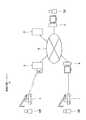
図1に示すように、遠隔監視システムAは、作業機1を、遠隔地に配置された監視端末2で監視するシステムである。作業機1はオペレータOPにより操作される。監視端末2はサービススタッフSSにより操作される。作業機1は通常複数であるが、1台でもよい。オペレータOPは各作業機1に配置される。監視端末2は1台でもよいし複数台でもよい。Next, an embodiment of the present invention will be described with reference to the drawings.
(overall structure)
First, the overall configuration of the remote monitoring system A according to an embodiment of the present invention will be described.
As shown in FIG. 1, the remote monitoring system A is a system that monitors the
遠隔監視システムAはサーバ3を備えている。サーバ3と監視端末2とはインターネットなどのネットワーク4を介して接続されており、相互に通信可能となっている。ネットワーク4には無線通信の基地局5と、データ取得用端末6とが接続されている。作業機1は基地局5との間で無線通信可能となっている。また、作業機1は保持する情報を直接または記憶媒体を介してデータ取得用端末6に伝達可能となっている。 The remote monitoring system A includes a
(作業機1)
つぎに、作業機1について説明する。
作業機1は、クレーン、高所作業車、軌陸車、油圧ショベルなどである。クレーンには移動式クレーン、固定式クレーンが含まれる。以下、移動式クレーンの場合を例に説明する。(Working machine 1)
Next, the
The
図2に示すように、移動式クレーン1には過負荷防止装置11、エンジンコントロールユニット15、車両制御装置16、コンビネーションメータ17、操作装置18、テレマティクスコントローラ19が備えられている。 As shown in FIG. 2, the
過負荷防止装置11は、移動式クレーン1の転倒に対する安定性や構成部材の強度を考慮して過負荷を防止する機能を有する。過負荷防止装置11は、その機能を実現するための制御装置12を備える。制御装置12は、CPUやメモリなどで構成されたコンピュータである。制御装置12は、過負荷防止装置11に関する情報(以下、「過負荷防止情報」という。)を保持している。過負荷防止情報としては、ブーム長さ、ブーム起伏角度、作業半径、定格総荷重、実荷重、アウトリガ張出し幅、異常発生情報(過負荷、センサ故障)などが挙げられる。 The
過負荷防止装置11は、表示装置13及び操作パネル14を備える。表示装置13と操作パネル14は、移動式クレーン1の運転室に設けられている。表示装置13は、液晶ディスプレイなどで構成され、過負荷防止情報を表示する。オペレータOPは、主にクレーン作業時に、表示装置13を参照する。操作パネル14は、複数のスイッチなどで構成されている。オペレータOPは、操作パネル14を操作することで、過負荷防止装置11の設定変更などを行うことができる。 The
移動式クレーン1には、車両走行や油圧機器を駆動するためのエンジンが搭載されている。エンジンは、エンジンコントロールユニット15で制御される。エンジンコントロールユニット15が保持する情報は、車両制御装置16に入力されている。 The
車両制御装置16は、移動式クレーン1の各種の制御を行う機能を有する。車両制御装置16はCPUやメモリなどで構成されたコンピュータである。車両制御装置16は車両走行に関する情報(以下、「車両走行情報」という。)を保持している。車両走行情報としては、車両速度、エンジン回転数、走行距離、燃料の量、エンジン冷却水の温度などが挙げられる。 The
コンビネーションメータ17は、移動式クレーン1の運転室に設けられている。コンビネーションメータ17は、車両制御装置16から取得した車両走行情報を表示する。オペレータOPは、主に車両走行時に、コンビネーションメータ17を参照する。 The
車両制御装置16には操作装置18が接続されている。操作装置18は、移動式クレーン1の運転室に設けられた各種のスイッチやレバーなどを含む。オペレータOPは、操作装置18を操作することで、移動式クレーン1の機能の切り換えや、設定の変更などを行うことができる。 An
テレマティクスコントローラ19は、移動式クレーン1の各種情報を収集し、記憶する機能と、記憶した情報を基地局5に無線送信する機能とを有する。テレマティクスコントローラ19は、CPUやメモリなどで構成されたコンピュータである。 The
本実施形態のテレマティクスコントローラ19は、過負荷防止装置11の制御装置12から過負荷防止情報を収集し、記憶する。また、車両制御装置16から車両走行情報を収集し、記憶する。以下、過負荷防止情報と車両走行情報とを合せて「機械状態情報」と称する。機械状態情報は、作業機の状態を示す情報の全てを含み、その一部であってもよい。機械状態情報は、過負荷防止情報および車両走行情報に限定されず、その他の情報が付加されてもよい。 The
テレマティクスコントローラ19は、例えば、記憶した機械状態情報を必要に応じて無線送信する。テレマティクスコントローラ19から送信された機械状態情報は、基地局5およびネットワーク4を介してサーバ3に伝送される。 For example, the
また例えば、テレマティクスコントローラ19は、記憶した機械状態情報をデータ取得用端末6に送信する。その構成は特に限定されない。例えば、テレマティクスコントローラ19とデータ取得用端末6とを、USBケーブルなどを介して直接接続し、テレマティクスコントローラ19からデータ取得用端末6へ機械状態情報を送信するように構成される。テレマティクスコントローラ19が、機械状態情報を記憶媒体に書き出し、その記憶媒体をデータ取得用端末6が読み込む構成としてもよい。 For example, the
データ取得用端末6は汎用のコンピュータである。データ取得用端末6が取得した機械状態情報はネットワーク4を介してサーバ3に伝送される。 The
過負荷防止装置11の表示装置13と、コンビネーションメータ17とは、それぞれ特許請求の範囲に記載の「第1の表示装置」、「第2の表示装置」に相当する。また、特許請求の範囲に記載の「作業機表示装置」は、第1の表示装置としての過負荷防止装置11の表示装置13と、第2の表示装置としてのコンビネーションメータ17を含む。作業機表示装置は機械状態情報を表示する装置である。作業機表示装置の構成は特に限定されず、液晶ディスプレイなどの汎用の表示装置でもよいし、コンビネーションメータ17などの専用の表示器でもよい。 The
過負荷防止装置11の操作パネル14と、操作装置18とは、それぞれ特許請求の範囲に記載の「作業機操作装置」に相当する。作業機操作装置は作業機の各種操作を行うための装置である。作業機操作装置の構成は特に限定されないが、スイッチやレバーなどで構成される。 The
過負荷防止装置11の表示装置13の表示態様は、作業機1によって異なる場合がある。例えば、国内仕様の作業機1と海外仕様の作業機1とでは異なる単位系で過負荷防止情報が表示される。また、作業機1の機種によっても表示する項目が異なる場合がある。同様に、コンビネーションメータ17の表示態様も作業機1によって異なる場合がある。 The display mode of the
なお、本明細書において「表示態様」とは、情報の表示形式の態様であり、グラフィック表示や表形式による表示などの表示形式の種類のほか、文字、数字、図形の配置、表示項目などを意味する。 In this specification, “display mode” is a mode of information display format. In addition to types of display formats such as graphic display and table display, characters, numbers, graphic layout, display items, etc. means.
過負荷防止装置11の操作パネル14の仕様は作業機1によって異なる場合がある。例えば、作業機1の機種によってスイッチの配置が異なる場合がある。同様に、操作装置18の仕様も作業機1によって異なる場合がある。 The specifications of the
(監視端末2)
つぎに、監視端末2のハードウエア構成について説明する。
図3に示すように、監視端末2は汎用のコンピュータである。監視端末2は、主にCPU21、メモリ22、ハードディスク23、通信部24、表示装置25、入力装置26から構成されている。通信部24はネットワーク4に接続し、通信する機能を有する。表示装置25は液晶ディスプレイなどである。入力装置26はキーボードやマウスなどである。(Monitoring terminal 2)
Next, the hardware configuration of the
As shown in FIG. 3, the
ハードディスク23にはOS(オペレーティング・システム)の他に、ウェブブラウザ用プログラム27がインストールされている。そのため、監視端末2はウェブブラウザを実行できる。 In addition to the OS (operating system), a
(サーバ3)
つぎに、サーバ3のハードウエア構成について説明する。
図4に示すように、サーバ3は、主にCPU31、メモリ32、ハードディスク33、通信部34から構成されている。通信部34はネットワーク4に接続し、通信する機能を有する。(Server 3)
Next, the hardware configuration of the
As shown in FIG. 4, the
ハードディスク33にはOS(オペレーティング・システム)の他に、データ収集プログラム35とデータ表示プログラム36とがインストールされている。また、ハードディスク33にはデータベースとしての機能を実現するために、データが格納されるデータ領域37が確保されている。 In addition to the OS (operating system), a
つぎに、データベース構成について説明する。
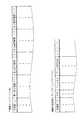
図5に示すように、データ領域37には、作業機マスタテーブルMと、機械状態情報トランザクションテーブルTとが記憶されている。Next, the database configuration will be described.
As shown in FIG. 5, the work area master table M and the machine state information transaction table T are stored in the
作業機マスタテーブルMは、データフィールドとして作業機ID、第1表示態様コード、第2表示態様コード、第1操作装置コード、第2操作装置コードを有している。作業機IDは作業機1の個体を識別するIDであり、予め作業機1ごとに一意の値が割り振られている。 The work machine master table M has a work machine ID, a first display mode code, a second display mode code, a first operating device code, and a second operating device code as data fields. The work machine ID is an ID for identifying an
第1表示態様コードは過負荷防止装置11の表示装置13の表示態様を識別するコードである。前述のごとく、表示装置13の表示態様は作業機1によって異なる場合がある。第1表示態様コードは、例えば、国内仕様の表示態様と海外仕様の表示態様とで異なる値が割り振られている。なお、第1表示態様コードを過負荷防止装置11の仕様を識別するコードで代用してもよい。 The first display mode code is a code for identifying the display mode of the
第2表示態様コードはコンビネーションメータ17の表示態様を識別するコードである。前述のごとく、コンビネーションメータ17の表示態様は作業機1によって異なる場合がある。第2表示態様コードは、例えば、国内仕様の表示態様と海外仕様の表示態様とで異なる値が割り振られている。なお、第2表示態様コードをコンビネーションメータ17の仕様を識別するコードで代用してもよい。 The second display mode code is a code for identifying the display mode of the
第1表示態様コードおよび第2表示態様コードは、それぞれ特許請求の範囲に記載の「表示態様コード」に相当する。表示態様コードは作業機表示装置の表示態様を識別するコードであればよい。 The first display mode code and the second display mode code each correspond to a “display mode code” recited in the claims. The display mode code may be a code that identifies the display mode of the work machine display device.
第1表示態様コードには、過負荷防止装置11の表示装置13(作業機表示装置)における表示態様を模した表示部データが関連付けられる。また、第2表示態様コードには、コンビネーションメータ17(作業機表示装置)における表示態様を模した表示部データが関連付けられる。すなわち、作業機マスタテーブルMは、作業機1ごとに作業機表示装置における表示態様を模した表示部データを予め記憶する「第1の記憶部」に相当する。 The first display mode code is associated with display unit data simulating a display mode on the display device 13 (work machine display device) of the
第1操作装置コードは過負荷防止装置11の操作パネル14の種類を識別するコードである。前述のごとく、操作パネル14の仕様は作業機1によって異なる場合がある。第1操作装置コードは操作パネル14の種類ごとに一意の値が割り振られている。なお、第1操作装置コードを過負荷防止装置11の仕様を識別するコードで代用してもよい。 The first operating device code is a code for identifying the type of the operating
第2操作装置コードは操作装置18の種類を識別するコードである。前述のごとく、操作装置18の仕様は作業機1によって異なる場合がある。第2操作装置コードは操作装置18の種類ごとに一意の値が割り振られている。 The second operating device code is a code for identifying the type of the operating
第1操作装置コードおよび第2操作装置コードは特許請求の範囲に記載の「操作装置コード」に相当する。操作装置コードは作業機操作装置の種類を識別するコードであればよい。 The first operating device code and the second operating device code correspond to the “operating device code” recited in the claims. The operating device code may be a code that identifies the type of work implement operating device.
第1操作装置コードには、過負荷防止装置11の操作パネル14(作業機操作装置)におけるスイッチ類の配置態様を模した操作部データが関連付けられる。また、第2操作装置コードには、操作装置18(作業機操作装置)におけるスイッチ類の配置態様を模した操作部データが関連付けられる。すなわち、作業機マスタテーブルMは、作業機1ごとに作業機操作装置におけるスイッチ類の配置態様を模した操作部データを記憶する「第3の記憶部」に相当する。 The first operation device code is associated with operation unit data imitating the arrangement of switches on the operation panel 14 (work machine operation device) of the
作業機マスタテーブルMには、監視対象の作業機1ごとに、当該作業機1の作業機ID、第1表示態様コード、第2表示態様コード、第1操作装置コード、第2操作装置コードが予め登録されている。 In the work machine master table M, the work machine ID, the first display mode code, the second display mode code, the first operation device code, and the second operation device code of the
機械状態情報トランザクションテーブルTは、データフィールドとして作業機ID、日時、機械状態情報の各種項目を有している。機械状態情報の項目としては、過負荷防止情報の項目と車両走行情報の項目とが含まれる。過負荷防止情報の項目は、例えばブーム長さ、ブーム起伏角度、作業半径、定格総荷重、実荷重、アウトリガ張出し幅である。車両走行情報の項目は、例えば車両速度、エンジン回転数、走行距離、燃料の量、エンジン冷却水の温度である。 The machine state information transaction table T has various items such as a work machine ID, date and time, and machine state information as data fields. The items of machine state information include items of overload prevention information and items of vehicle travel information. The items of overload prevention information are, for example, boom length, boom hoisting angle, working radius, rated total load, actual load, and outrigger extension width. The items of vehicle travel information are, for example, vehicle speed, engine speed, travel distance, fuel amount, and engine coolant temperature.
機械状態情報トランザクションテーブルTには、後述のデータ収集処理により、各作業機1の機械状態情報を示す機械状態データが登録される。すなわち、機械状態情報トランザクションテーブルTは、作業機1から取得した機械状態情報を示す機械状態データを順次記憶する「第2の記憶部」に相当する。 In the machine state information transaction table T, machine state data indicating the machine state information of each
以上のように、サーバ3には、作業機1の作業機IDと紐付けて、その作業機1の機械状態情報と表示態様コードと操作装置コードとが記憶されている。 As described above, the
(データ取得処理)
つぎに、データ取得処理について説明する。
データ取得処理のうちサーバ3が行う処理は、サーバ3のCPU31がデータ収集プログラム35を実行することで行われる。(Data acquisition process)
Next, the data acquisition process will be described.
Of the data acquisition processing, processing performed by the
作業機1のテレマティクスコントローラ19には機械状態情報が記憶されている。テレマティクスコントローラ19は、当該作業機1の作業機IDと、機械状態情報が収集された日時と、機械状態情報とを無線送信する。ここで、機械状態情報を収集するタイミング、機械状態情報を無線送信するタイミングは特に限定されない。作業機1に何らかの問題が発生したタイミングで、機械状態情報の収集、無線送信を行ってもよいし、一定周期で機械状態情報の収集、無線送信を行ってもよい。テレマティクスコントローラ19から送信された各種のデータ(機械状態データを含む)は基地局5およびネットワーク4を介してサーバ3に伝送される。 Machine state information is stored in the
また、テレマティクスコントローラ19は、記憶している機械状態情報をデータ取得用端末6に送信してもよい。この場合、機械状態情報はデータ取得用端末6からネットワーク4を介してサーバ3に伝送される。 Further, the
サーバ3は、作業機IDと日時と機械状態情報とからなるデータを作業機1から受け付けた場合、それらのデータを機械状態情報トランザクションテーブルTに追加する。 When the
以上の処理を繰り返し行うことで、機械状態情報トランザクションテーブルTには、種々の作業機1の種々の日時における機械状態情報が登録される。 By repeatedly performing the above processing, machine state information at various dates and times for
(データ表示処理)
つぎに、図6に基づき、データ表示処理について説明する。
データ表示処理のうちサーバ3が行う処理は、サーバ3のCPU31がデータ表示プログラム36を実行することで行われる。すなわち、CPU31は、監視端末2の表示装置25(表示部)に画像を表示させる表示処理部として機能する。(Data display processing)
Next, the data display process will be described with reference to FIG.
Of the data display processing, processing performed by the
まず、サービススタッフSSは監視端末2に搭載されたウェブブラウザで遠隔監視サイトに接続する(ステップS11)。サーバ3は、監視端末2からの接続に伴いデータ表示プログラム36を呼び出し、遠隔監視画面をHTML形式などで監視端末2に送信する(ステップS21)。 First, the service staff SS connects to the remote monitoring site using a web browser installed in the monitoring terminal 2 (step S11). The
ステップS21において、サーバ3は、機械状態情報トランザクションテーブルTを参照し、作業機IDと日時とを取得する。そして、サーバ3は、作業機IDおよび日時からなるリストを含む遠隔監視画面を生成し、送信する。 In step S <b> 21, the
サーバ3から遠隔監視画面が送信されると、監視端末2のウェブブラウザに遠隔監視画面が表示される(ステップS12)。サービススタッフSSは、遠隔監視画面に含まれるリストから、特定の作業機、日時を指定できる。サービススタッフSSが特定の作業機、日時を指定すると、その情報がサーバ3に送信される(ステップS13)。 When the remote monitoring screen is transmitted from the
サーバ3は、監視端末2から特定の作業機、日時が指定された場合に、機械状態情報トランザクションテーブルTを参照し、指定された作業機の作業機ID、日時に対応する機械状態情報を取得する(ステップS22)。 When a specific work machine and date / time are designated from the
つぎに、サーバ3は作業機表示装置における表示態様を模擬した表示部模擬画像と、作業機操作装置における表示態様を模擬した操作部模擬画像とを生成する(ステップS23)。以下、種々の模擬画像を順に説明する。 Next, the
過負荷防止装置11の表示装置13の表示部模擬画像I1および過負荷防止装置11の操作パネル14の操作部模擬画像I2の生成は、以下の手順で行われる。
まず、サーバ3は、作業機マスタテーブルMを参照し、指定された作業機の作業機IDに対応する第1表示態様コードおよび第1操作装置コードを取得する。つぎに、サーバ3は、ステップS22で取得した機械状態情報(過負荷防止情報)を第1表示態様コードが示す表示態様で表示した表示部模擬画像I1(第1の表示部模擬画像)を生成する。また、サーバ3は、第1操作装置コードに対応する操作部模擬画像I2を生成する。Generation of the display unit simulated image I1 of the
First, the
ここで、データ表示プログラム36には、各表示態様コード、各操作装置コードに対応する模擬画像生成プログラムが含まれている。模擬画像生成プログラムは、作業機1ごとに作業機表示装置における表示態様を模した表示部データ、及び作業機1ごとに作業機操作装置におけるスイッチ類の配置態様を模した操作部データを有する。サーバ3は、取得された表示態様コードまたは操作装置コードに対応する模擬画像生成プログラムを実行することで、対応する模擬画像を生成する。 Here, the
すなわち、サーバ3は、指定された作業機1に対応する表示部データ(第1表示態様コードに関連付けられた表示部データ)及び当該作業機1から取得した機械状態データに基づいて、過負荷防止装置11の表示装置13(作業機表示装置)における表示態様を模擬した表示部模擬画像を生成する(図7参照)。具体的には、サーバ3は、表示部データに含まれる作業機1を示す図形データと機械状態データを合成して表示部模擬画像を生成する。図7におけるクレーンを示す画像データが、図形データである。 That is, the
また、サーバ3は、指定された作業機1に対応する操作部データ(第1操作装置コードに関連付けられた操作部データ)に基づいて、作業機操作装置における配置態様を模擬した操作部模擬画像を生成する(図7参照)。 The
上記の処理で生成された表示部模擬画像I1、操作部模擬画像I2は図7に示すような画像である。表示部模擬画像I1は、過負荷防止装置11の表示装置13を模擬した画像であり、機械状態情報の表示態様も模擬されている。操作部模擬画像I2は過負荷防止装置11の操作パネル14を模擬した画像である。 The display unit simulated image I1 and the operation unit simulated image I2 generated by the above processing are images as shown in FIG. The display unit simulated image I1 is an image simulating the
前記表示部模擬画像I1は、過負荷防止装置11の通常画面を再現したものであるが、サーバ3は、他の画面を再現した模擬画像I3を生成してもよい。図8に示す模擬画像I3は過負荷防止装置11のメンテナンス画面を再現した画像(以下「メンテナンス模擬画像」と称する)である。この場合、機械状態情報は、作業機1のメンテナンスに用いるメンテナンス情報を含む。メンテナンス情報を示すデータは、機械状態情報トランザクションテーブルTに記憶される。 The display unit simulated image I1 is a reproduction of the normal screen of the
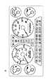
コンビネーションメータ17の表示部模擬画像I4の生成は以下の手順で行われる。
まず、サーバ3は、作業機マスタテーブルMを参照し、指定された作業機の作業機IDに対応する第2表示態様コードを取得する。つぎに、サーバ3は、ステップS22で取得した機械状態情報(車両走行情報)を第2表示態様コードが示す表示態様で表示した表示部模擬画像I4(第2の表示部模擬画像)を生成する。上記の処理で生成された表示部模擬画像I4は図9に示すような画像である。The display unit simulated image I4 of the
First, the
操作装置18の模擬画像I5の生成は以下の手順で行われる。
まず、サーバ3は、作業機マスタテーブルMを参照し、指定された作業機の作業機IDに対応する第2操作装置コードを取得する。つぎに、サーバ3は、第2操作装置コードに対応する操作部模擬画像I5を生成する。上記の処理で生成された操作部模擬画像I5は図10に示すような画像である。図10に示す例は、作業機1の運転室に設けられたスイッチを示している。Generation of the simulated image I5 of the operating
First, the
図6に戻り説明する。サーバ3は生成した模擬画像I1〜I5を監視端末2に送信する(ステップS24)。サーバ3から模擬画像I1〜I5が送信されると、監視端末2のウェブブラウザに模擬画像I1〜I5が表示される(ステップS14)。サービススタッフSSは模擬画像I1〜I5を参照することで、指定した作業機の機械状態情報の確認や、作業機操作装置の構成を確認できる。 Returning to FIG. The
以上のように、監視端末2には機械状態情報が作業機表示装置の表示態様を模擬した表示態様で表示される。そのため、作業機1のオペレータOPと端末側のサービススタッフSSとが同じ態様の表示を見ることになる。その結果、オペレータOPとサービススタッフSSとが共通の認識を得ることができ、双方の意思疎通が容易となる。例えば、オペレータOPとサービススタッフSSとの間で母国語の違いがある場合でも、双方の意思疎通が容易である。 As described above, the machine state information is displayed on the
また、監視端末2には作業機操作装置を模擬した画像が表示される。そのため、電話やメールを通してサービススタッフSSがオペレータOPに操作の指示を行いやすい。 The
オペレータOPとサービススタッフSSとの意思疎通が容易であるので、作業機1に何らかの問題が発生した場合でも、その問題を早期に解決することができる。その結果、作業機1のダウンタイムを短縮できる。 Since communication between the operator OP and the service staff SS is easy, even when a problem occurs in the
ところで、ステップS13においてサービススタッフSSが他の作業機を指定した場合、ステップS23においてサーバ3は前記模擬画像I1〜I5とは異なる態様の模擬画像を生成する場合がある。 By the way, when the service staff SS designates another work machine in step S13, the
例えば、サーバ3は、図11に示すような表示部模擬画像I6、及び操作部模擬画像I7を生成する。表示部模擬画像I6は過負荷防止装置11の表示装置13を模擬した画像である。表示部模擬画像I6は図7に示す表示部模擬画像I1とは単位系やクレーンを示す図形(表示部データに含まれる図形データ)が異なる。表示部模擬画像I1は国内仕様の表示態様、模擬画像I6は海外仕様の表示形態である。操作部模擬画像I7は過負荷防止装置11の操作パネル14を模擬した画像である。操作部模擬画像I7は図7に示す操作部模擬画像I2とはスイッチの配置が異なる。操作部模擬画像I2と操作部模擬画像I7とは、過負荷防止装置11の仕様の違いにより異なる画像となる。具体的には、表示部模擬画像I1は、メートル法の単位系で表示されており、表示部模擬画像I6は、ヤードポンド法の単位系で表示されている。サーバ3は、作業機1からの機械状態データに基づいて、対応する単位系に換算した値を算出し、表示部模擬画像I1、I6に表示する。 For example, the
また、サーバ3は図12に示すような表示部模擬画像I8を生成する。表示部模擬画像I8はコンビネーションメータ17を模擬した画像である。表示部模擬画像I8は図9に示す表示部模擬画像I4とは単位系が異なる。表示部模擬画像I4は国内仕様の表示態様、表示部模擬画像I8は海外仕様の表示態様である。具体的には、表示部模擬画像I4では、速度計がメートル法の単位系(km/h)で表示されており、表示部模擬画像I8では、速度計がメートル法及びヤードポンド法の単位系(km/h及びMPH)で表示されている。サーバ3は、作業機1からの機械状態データに基づいて、対応する単位系に換算した値を算出し、表示部模擬画像I4、I8に表示する。 Further, the
なお、機械状態情報にテキスト情報が含まれる場合は、サーバ3は、各作業機1における表示言語に応じて、表示部模擬画像における表示言語を切り替えてもよい。また、機械状態情報を表示する際の単位系及び表示言語は、監視端末2のウェブブラウザ上で選択できるようにしてもよい。 When text information is included in the machine state information, the
このように、実施の形態に係るサーバ3は、複数の作業機1と、表示装置25(表示部)を備える監視端末2とに、ネットワークを介して接続される。複数の作業機1は、機械状態情報を表示する過負荷防止装置11の表示装置13、コンビネーションメータ17(作業機表示装置)及び所定の操作に供される過負荷防止装置11の操作パネル14、操作装置18(作業機操作装置)を備える。サーバ3は、作業機1ごとに作業機表示装置における表示態様を模した表示部データを予め記憶する作業機マスタテーブルM(第1の記憶部)と、作業機1から取得した機械状態情報を示す機械状態データを順次記憶する機械状態情報トランザクションテーブルT(第2の記憶部)と、監視端末2からの要求に応じて、特定の作業機1に対応する表示部データ及び当該特定の作業機1から取得した機械状態データに基づいて、作業機表示装置における表示態様を模擬した表示部模擬画像を生成し、表示装置25に表示させるCPU31(表示処理部)と、を備える。 As described above, the
実施の形態に係る遠隔監視システムAは、作業機1ごとに作業機表示装置における表示態様を模した表示部データを予め記憶する作業機マスタテーブルM(第1の記憶部)と、作業機1から取得した機械状態情報を示す機械状態データを順次記憶する機械状態情報トランザクションテーブルT(第2の記憶部)と、特定の作業機1に対応する表示部データ及び当該特定の作業機1から取得した機械状態データに基づいて、作業機表示装置における表示態様を模擬した表示部模擬画像を生成するサーバ3のCPU31(表示処理部)と、表示部模擬画像を表示する監視端末2の表示装置25(表示部)と、を備える。 The remote monitoring system A according to the embodiment includes a work machine master table M (first storage unit) that stores in advance display unit data that mimics the display mode of the work machine display device for each
実施の形態に係る遠隔監視システムAにおける遠隔監視方法は、各作業機1から機械状態情報を示す機械状態データを取得して順次記憶する工程と、監視対象の作業機を特定する指示を受け付ける工程(図6のステップS13)と、特定された監視対象の作業機1に対応する表示部データ及び当該監視対象の作業機1から取得した機械状態情報を示す機械状態データに基づいて、作業機表示装置における表示態様を模擬した表示部模擬画像を生成する工程(ステップS22、S23)と、表示部模擬画像を表示する工程(ステップS14)と、を備える。 The remote monitoring method in the remote monitoring system A according to the embodiment includes a step of acquiring and sequentially storing machine state data indicating machine state information from each
以上のように、監視端末2には、指定した作業機1の機械状態情報が、当該作業機1の表示態様コードが示す表示態様で表示される。そのため、作業機表示装置の表示態様が作業機1ごとに異なっていたとしても、監視端末2には指定した作業機1の機械状態情報を、その作業機に対応する表示態様で表示できる。そのため、オペレータOPとサービススタッフSSとが同じ態様の表示を見ることができる。 As described above, the machine state information of the designated
また、監視端末2には、指定した作業機1の操作装置コードに対応する画像が表示される。そのため、作業機操作装置が作業機1の個体ごとに異なっていたとしても、監視端末2には指定した作業機の作業機操作装置を模擬した画像を表示できる。そのため、サービススタッフSSがオペレータOPに操作の指示を行いやすい。 The
〔その他の実施形態〕
前記実施形態は、模擬画像生成処理(ステップS23)をサーバ3が行う構成であるが、この処理の一部または全部を監視端末2が行ってもよい。監視端末2が模擬画像生成処理を行う場合には、例えば以下の処理が行われる。サーバ3はステップS22で取得した作業機情報を監視端末2に送信する。また、サーバ3は指定された作業機の表示態様コード、操作装置コードを監視端末2に送信する。監視端末2は予めインストールされた模擬画像生成プログラムを実行して、模擬画像を生成する。[Other Embodiments]
In the embodiment, the
サーバ3の機能を監視端末2が行ってもよい。すなわち、一台のコンピュータにサーバ3の機能と監視端末2の機能とを搭載してもよい。 The
前記実施形態は、監視端末2に搭載されたウェブブラウザを利用したが、これに代えて、専用のアプリケーションを用いてもよい。 In the above-described embodiment, the web browser installed in the
前記実施形態は、監視端末2に模擬画像を表示するよう構成したが、これに限定されない。監視端末2には機械状態情報が作業機表示装置の表示態様を模擬した表示態様で表示されればよい。 Although the said embodiment was comprised so that a simulation image might be displayed on the
監視端末2の表示対象は、過負荷防止装置11の表示装置13、コンビネーションメータ17、過負荷防止装置11の操作パネル14、操作装置18に限定されない。 The display target of the
作業機1が保持する情報の一部を、サーバ3を介することなく直接監視端末2に送信し、その情報を監視端末2に表示する構成としてもよい。 A part of the information held by the
さらには、表示部模擬画像及び操作部模擬画像を、同時に表示してもよいし、選択的に表示してもよい。また、表示部模擬画像又は操作部模擬画像が複数種類ある場合、これらを同時に表示してもよいし、選択的に表示してもよい。 Furthermore, the display unit simulated image and the operation unit simulated image may be displayed simultaneously or selectively. In addition, when there are a plurality of types of display unit simulated images or operation unit simulated images, these may be displayed simultaneously or selectively.
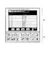
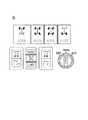
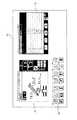
図13、図14は、表示部模擬画像及び操作部模擬画像を同時に表示した場合の表示例を示す。図13に示す表示画面D1では、過負荷防止装置11の表示装置13を模した表示部模擬画像I1、操作パネル14を模した操作部模擬画像I2及びメンテナンス情報の表示画面を模したメンテナンス模擬画像I4が、一画面に表示されている。図14に示す表示画面D2では、コンビネーションメータ17を模した表示部模擬画像I4、操作装置18を模した操作部模擬画像I5及びメンテナンス情報の表示画面を模したメンテナンス模擬画像I4が、一画面に表示されている。表示部模擬画像及び/又は操作部模擬画像とともにメンテナンス模擬画像を表示することにより、サービススタッフSSは異常発生の原因を特定しやすくなり、オペレータOPに対してより的確な指示を行うことができる。 13 and 14 show display examples when a display unit simulated image and an operation unit simulated image are displayed simultaneously. In the display screen D1 shown in FIG. 13, a display simulation image I1 simulating the
A 遠隔監視システム
1 作業機
2 監視端末
3 サーバ
4 ネットワーク
5 基地局
6 データ取得用端末
11 過負荷防止装置
12 制御装置
13 表示装置(作業機表示装置、第1の表示装置)
14 操作パネル(作業機操作装置)
15 エンジンコントロールユニット
16 車両制御装置
17 コンビネーションメータ(作業機表示装置、第2の表示装置)
18 操作装置(作業機操作装置)
19 テレマティクスコントローラ
31 CPU(表示処理部)
M 作業機マスタテーブル(第1の記憶部、第3の記憶部)
T 機械状態情報トランザクションテーブル(第2の記憶部)A
14 Operation panel (work machine operation device)
15
18 Operation device (work machine operation device)
19
M work machine master table (first storage unit, third storage unit)
T machine state information transaction table (second storage unit)
Claims (10)
Translated fromJapanese前記作業機ごとに前記作業機表示装置における表示態様を模した表示部データを予め記憶する第1の記憶部と、
前記作業機から前記作業機を識別する作業機ID及び日時情報と共に取得した前記機械状態情報を示す機械状態データを、順次記憶する第2の記憶部と、
前記監視端末から指定された前記作業機の前記表示部データと前記監視端末から指定された日時の前記作業機の前記機械状態データとに基づいて、前記作業機表示装置における表示態様を模擬した表示部模擬画像を生成し、前記監視端末の表示部に前記表示部模擬画像を含むメンテナンス画面を表示させる表示処理部と、を備えることを特徴とするサーバ。A network is connected to a work machine display device that displays machine status information and a plurality of work machines that include a work machine operation device that is used for a predetermined operation, anda monitoring terminal that includes a display unitand remotely monitors the information on the work machine. Amaintenance server connected via
A first storage unit that stores in advance display unit data simulating the display mode of the work implement display device for each work implement;
A second storage unit that sequentially stores machine state data indicating the machine state information acquiredtogether with a work machine ID and date / time information for identifying the work machine from thework machine ;
Display simulating the display mode of the work implement display device based on the display unitdata of the work implement designated from the monitoring terminal and the machine state data of the work implement of the date and time designated from the monitoring terminal A display processing unit that generates a simulated part image anddisplays a maintenance screen including the simulated display part image onthe display unit of themonitoring terminal .
まず、作業機ID及び日時からなるリストを含む遠隔監視画面を前記監視端末に提示し、 First, present a remote monitoring screen including a list of work implement ID and date and time to the monitoring terminal,
次いで、前記監視端末から指定された前記作業機の前記表示部データと指定された日時の前記作業機の前記機械状態データとを合成して表示部模擬画像として提示することを特徴とする請求項1に記載のサーバ。 Next, the display unit data specified by the monitoring terminal and the machine state data of the work device specified by the specified date and time are combined and presented as a display unit simulated image. 1. The server according to 1.
前記表示処理部は、前記操作部データに基づいて、前記作業機操作装置における前記配置態様を模擬した操作部模擬画像を生成し、前記表示部模擬画像とともに前記操作部模擬画像を、前記表示部に表示させることを特徴とする請求項1に記載のサーバ。A third storage unit that stores operation unit data imitating an arrangement mode of switches in the work machine operation device for each work machine;
The display processing unit generates, based on the operation unit data, an operation unit simulation image that simulates the arrangement mode in the work machine operation device, and displays the operation unit simulation image together with the display unit simulation image. The server according to claim 1, wherein the server is displayed.
前記第2の記憶部は、前記作業機IDと紐付けて、前記機械状態情報を記憶することを特徴とする請求項1に記載のサーバ。The first storage section, priorSymbol Operation industry machine ID and in association, stores display mode code that identifies the display mode of the working machine display device,
The server according to claim 1, wherein the second storage unit stores the machine state information in association with the work machine ID.
前記表示処理部は、前記表示部模擬画像ともに対応する前記メンテナンス情報を、前記表示部に、同時又は選択的に表示させることを特徴とする請求項1に記載のサーバ。The machine state information includes maintenance information used for maintenance of the working machine,
The server according to claim 1, wherein the display processing unit causes the display unit to simultaneously or selectively display the maintenance information corresponding to the display unit simulated image.
前記作業機表示装置は、前記過負荷防止情報を表示する第1の表示装置と、前記車両走行情報を表示する第2の表示装置と、を有し、
前記表示処理部は、前記第1の表示装置の表示態様を模擬した第1の表示部模擬画像と前記第2の表示装置の表示態様を模擬した第2の表示部模擬画像を、前記表示部に、同時に又は選択的に表示させることを特徴とする請求項1に記載のサーバ。The machine state information includes overload prevention information for preventing an overload state in the work implement and vehicle running information related to the running of the work implement,
The work implement display device includes a first display device that displays the overload prevention information, and a second display device that displays the vehicle travel information,
The display processing unit displays a first display unit simulated image simulating the display mode of the first display device and a second display unit simulated image simulating the display mode of the second display device, The server according to claim 1, wherein the servers are displayed simultaneously or selectively.
前記表示処理部は、前記表示言語又は単位系に関するデータに基づいて、前記表示部模擬画像における前記機械状態情報の表示を切り替えることを特徴とする請求項1に記載のサーバ。The display unit data includes data relating to a display language or a unit system used in the work implement display device,
The server according to claim 1, wherein the display processing unit switches display of the machine state information in the display unit simulated image based on data related to the display language or unit system.
前記作業機ごとに前記作業機表示装置における表示態様を模した表示部データを予め記憶する第1の記憶部と、
前記作業機から前記作業機を識別する作業機ID及び日時情報と共に取得した前記機械状態情報を示す機械状態データを、順次記憶する第2の記憶部と、
監視端末から指定された前記作業機の前記表示部データと前記監視端末から指定された日時の前記作業機の前記機械状態データとに基づいて、前記作業機表示装置における表示態様を模擬した表示部模擬画像を生成する表示処理部と、
前記表示部模擬画像を含むメンテナンス画面を表示する表示部と、を備えることを特徴とする遠隔監視システム。A remote monitoring system connected via a network to a plurality of work machines provided with a work machine display device for displaying machine state information and a work machine operation device used for a predetermined operation,
A first storage unit that stores in advance display unit data simulating the display mode of the work implement display device for each work implement;
The machine state data indicatingthe machine state information acquiredwith the working machine ID and the date and time information identifying the working machine from the workingmachine, a second storage unit for sequentially storing,
A display unit that simulates a display mode in the work implement display device based on the display unitdata of the work implement specified from the monitoring terminal and the machine state data of the work implement of the date and time specified from the monitoring terminal A display processing unit for generating a simulated image;
And a display unitfor displaying amaintenance screen including the display unit simulated image.
前記作業機ごとに前記作業機表示装置における表示態様を模した表示部データを、第1の記憶部に予め記憶する工程と、
前記作業機から前記作業機を識別する作業機ID及び日時情報と共に取得した前記機械状態情報を示す機械状態データを、第2の記憶部に順次記憶する工程と、
前記監視端末から指定された前記作業機の前記表示部データと前記監視端末から指定された日時の前記作業機の前記機械状態データとに基づいて、前記作業機表示装置における表示態様を模擬した表示部模擬画像を生成する工程と、
前記表示部模擬画像を含むメンテナンス画面を、前記監視端末の表示部に提示する工程と、を備えることを特徴とする遠隔監視方法。A network is connected to a work machine display device that displays machine status information and a plurality of work machines thatinclude a work machine operation device that is used for a predetermined operation, anda monitoring terminal that includes a display unit and remotely monitors the information on the work machine. A remote monitoring methodprovided by a maintenance server connected via
Storing the display unit data imitating the display mode in the work machine display device for each work machine in the first storage unit in advance;
Sequentially storing machine state data indicating the machine state informationacquired together with a work machine ID and date information identifying the work machine from thework machine in asecond storage unit ;
Display simulating the display mode of the work implement display device based on the display unitdata of the work implement designated from the monitoring terminal and the machine state data of the work implement of the date and time designated from the monitoring terminal Generating a simulated part image;
Anda stepof presenting a maintenance screen including the display unit simulated image ona display unit of the monitoring terminal .
Priority Applications (4)
| Application Number | Priority Date | Filing Date | Title |
|---|---|---|---|
| EP17747531.6AEP3413578B1 (en) | 2016-02-02 | 2017-02-02 | Server, remote monitoring system, and remote monitoring method |
| CN201780008318.6ACN108605173B (en) | 2016-02-02 | 2017-02-02 | Server, remote monitoring system and remote monitoring method |
| PCT/JP2017/003825WO2017135380A1 (en) | 2016-02-02 | 2017-02-02 | Server, remote monitoring system, and remote monitoring method |
| US16/071,971US11579581B2 (en) | 2016-02-02 | 2017-02-02 | Server, remote monitoring system, and remote monitoring method |
Applications Claiming Priority (2)
| Application Number | Priority Date | Filing Date | Title |
|---|---|---|---|
| JP2016018052 | 2016-02-02 | ||
| JP2016018052 | 2016-02-02 |
Related Child Applications (3)
| Application Number | Title | Priority Date | Filing Date |
|---|---|---|---|
| JP2017097325ADivisionJP6328824B2 (en) | 2016-02-02 | 2017-05-16 | Work machine management device and work machine management method |
| JP2017098131ADivisionJP6328825B2 (en) | 2016-02-02 | 2017-05-17 | Management method of work equipment |
| JP2017098129ADivisionJP6859843B2 (en) | 2016-02-02 | 2017-05-17 | Work machine management device and work machine management method |
Publications (2)
| Publication Number | Publication Date |
|---|---|
| JP6147406B1true JP6147406B1 (en) | 2017-06-14 |
| JP2017139737A JP2017139737A (en) | 2017-08-10 |
Family
ID=59061224
Family Applications (4)
| Application Number | Title | Priority Date | Filing Date |
|---|---|---|---|
| JP2016219933AActiveJP6147406B1 (en) | 2016-02-02 | 2016-11-10 | Server, remote monitoring system and remote monitoring method |
| JP2017097325AActiveJP6328824B2 (en) | 2016-02-02 | 2017-05-16 | Work machine management device and work machine management method |
| JP2017098131AActiveJP6328825B2 (en) | 2016-02-02 | 2017-05-17 | Management method of work equipment |
| JP2017098129AActiveJP6859843B2 (en) | 2016-02-02 | 2017-05-17 | Work machine management device and work machine management method |
Family Applications After (3)
| Application Number | Title | Priority Date | Filing Date |
|---|---|---|---|
| JP2017097325AActiveJP6328824B2 (en) | 2016-02-02 | 2017-05-16 | Work machine management device and work machine management method |
| JP2017098131AActiveJP6328825B2 (en) | 2016-02-02 | 2017-05-17 | Management method of work equipment |
| JP2017098129AActiveJP6859843B2 (en) | 2016-02-02 | 2017-05-17 | Work machine management device and work machine management method |
Country Status (5)
| Country | Link |
|---|---|
| US (1) | US11579581B2 (en) |
| EP (1) | EP3413578B1 (en) |
| JP (4) | JP6147406B1 (en) |
| CN (1) | CN108605173B (en) |
| WO (1) | WO2017135380A1 (en) |
Cited By (1)
| Publication number | Priority date | Publication date | Assignee | Title |
|---|---|---|---|---|
| JP2023061535A (en)* | 2021-10-20 | 2023-05-02 | 大成建設株式会社 | Construction machine work management system and work management method |
Families Citing this family (14)
| Publication number | Priority date | Publication date | Assignee | Title |
|---|---|---|---|---|
| US12020517B2 (en)* | 2018-01-26 | 2024-06-25 | Tadano Ltd. | Wireless communication device, work vehicle, and work vehicle wireless communication system |
| JP7063652B2 (en)* | 2018-02-19 | 2022-05-09 | 株式会社デンソーテン | Vehicle remote control device, vehicle remote control system and vehicle remote control method |
| KR102541178B1 (en)* | 2018-03-30 | 2023-06-09 | 엘에스엠트론 주식회사 | Server and Method for Remote Maintenance of Injection Machine |
| US12208996B2 (en)* | 2018-08-02 | 2025-01-28 | Tadano Ltd. | Operation assistance module, image generation application, and work machine |
| JP7249879B2 (en)* | 2018-10-05 | 2023-03-31 | パナソニック インテレクチュアル プロパティ コーポレーション オブ アメリカ | Information processing method and information processing system |
| CN111047733B (en)* | 2018-10-15 | 2022-04-22 | 香港城市大学深圳研究院 | Unmanned vehicle state monitoring control system |
| JP6790308B1 (en)* | 2019-04-25 | 2020-11-25 | 三菱電機株式会社 | Screen data generation system, screen data generation method and program |
| WO2021085608A1 (en)* | 2019-10-31 | 2021-05-06 | 住友建機株式会社 | Shovel management system, portable terminal for shovel, and program used in portable terminal for shovel |
| JP7310595B2 (en)* | 2019-12-24 | 2023-07-19 | コベルコ建機株式会社 | Work support server and work support system |
| JP7409074B2 (en)* | 2019-12-25 | 2024-01-09 | コベルコ建機株式会社 | How to select work support server and imaging device |
| JP6997823B2 (en)* | 2020-03-16 | 2022-01-18 | 日立建機株式会社 | Work machine |
| CN113742168B (en)* | 2021-08-11 | 2024-08-13 | 江门市阳邦智能科技有限公司 | Internet of things data monitoring method, device and system and computer readable storage medium |
| EP4174014A1 (en)* | 2021-11-02 | 2023-05-03 | Hiab AB | A loader crane system |
| CN114408748A (en)* | 2022-03-21 | 2022-04-29 | 杭州杰牌传动科技有限公司 | State data monitoring and transmitting system and method for remote control of intelligent tower crane |
Family Cites Families (30)
| Publication number | Priority date | Publication date | Assignee | Title |
|---|---|---|---|---|
| US8472942B2 (en)* | 2000-06-12 | 2013-06-25 | I/O Controls Corporation | System and method for facilitating diagnosis and maintenance of a mobile conveyance |
| JP2002044765A (en)* | 2000-07-28 | 2002-02-08 | Matsushita Electric Ind Co Ltd | Remote control system and gateway device |
| JP2002190871A (en)* | 2000-12-20 | 2002-07-05 | Yanmar Agricult Equip Co Ltd | Work machine maintenance system |
| JP4897152B2 (en)* | 2001-05-08 | 2012-03-14 | 日立建機株式会社 | Construction machine failure diagnosis method and construction machine failure diagnosis system |
| JP2004075206A (en)* | 2002-08-09 | 2004-03-11 | Hitachi Constr Mach Co Ltd | Information display device for construction machine |
| EP1441077B1 (en)* | 2003-01-24 | 2011-03-16 | Komatsu Ltd. | Work machine management device |
| JP2007536634A (en)* | 2004-05-04 | 2007-12-13 | フィッシャー−ローズマウント・システムズ・インコーポレーテッド | Service-oriented architecture for process control systems |
| JP4655219B2 (en)* | 2005-10-19 | 2011-03-23 | 日立建機株式会社 | Display device for work equipment |
| US9334820B2 (en)* | 2006-07-11 | 2016-05-10 | Komatsu Ltd. | Working machine component monitoring system |
| US9120494B2 (en)* | 2006-12-04 | 2015-09-01 | General Electric Company | System, method and computer software code for remotely assisted operation of a railway vehicle system |
| US8139108B2 (en)* | 2007-01-31 | 2012-03-20 | Caterpillar Inc. | Simulation system implementing real-time machine data |
| US7683771B1 (en)* | 2007-03-26 | 2010-03-23 | Barry Loeb | Configurable control panel and/or dashboard display |
| US8195231B2 (en)* | 2007-10-31 | 2012-06-05 | Caterpillar Inc. | System for collection and distribution of machine data via a cellular device |
| US9206589B2 (en)* | 2009-03-31 | 2015-12-08 | Caterpillar Inc. | System and method for controlling machines remotely |
| JP2010248777A (en)* | 2009-04-15 | 2010-11-04 | Caterpillar Sarl | Management system of working machine |
| JP2011038273A (en)* | 2009-08-07 | 2011-02-24 | Caterpillar Sarl | Remote diagnosis system for working machine |
| US20110130905A1 (en)* | 2009-12-01 | 2011-06-02 | Ise Corporation | Remote Vehicle Monitoring and Diagnostic System and Method |
| JP5722185B2 (en) | 2011-09-30 | 2015-05-20 | 日立住友重機械建機クレーン株式会社 | Hydraulic device |
| JP5924961B2 (en) | 2012-02-02 | 2016-05-25 | 住友建機株式会社 | Construction machine, construction machine management system, portable communication terminal, and method for displaying work status of construction machine |
| CN102830648B (en)* | 2012-08-31 | 2015-09-30 | 中联重科股份有限公司 | Monitoring method, monitoring equipment and monitoring system for operation of washing and sweeping vehicle and washing and sweeping vehicle |
| WO2014047641A1 (en)* | 2012-09-24 | 2014-03-27 | Caterpillar Inc. | Mining operation control and review |
| US9213331B2 (en)* | 2012-12-19 | 2015-12-15 | Caterpillar Inc. | Remote control system for a machine |
| JP2014173244A (en)* | 2013-03-06 | 2014-09-22 | Tadano Ltd | Display system for work machine |
| WO2014136956A1 (en)* | 2013-03-08 | 2014-09-12 | 日立建機株式会社 | Management server for work machine and management method for work machine |
| US9183681B2 (en)* | 2013-07-31 | 2015-11-10 | Bosch Automotive Service Solutions Inc. | Diagnostic tool with parts ordering system |
| JP2015068109A (en)* | 2013-09-30 | 2015-04-13 | 日立建機株式会社 | Display device for vehicle |
| JP6302391B2 (en)* | 2014-10-07 | 2018-03-28 | ヤンマー株式会社 | Remote server |
| EP3245340A1 (en)* | 2015-01-15 | 2017-11-22 | Modustri LLC | Configurable monitor and parts management system |
| CN107408272A (en)* | 2015-04-28 | 2017-11-28 | 株式会社小松制作所 | member information management system |
| US10515492B2 (en)* | 2015-12-11 | 2019-12-24 | Cummins, Inc. | Diagnostic data visualization methods |
- 2016
- 2016-11-10JPJP2016219933Apatent/JP6147406B1/enactiveActive
- 2017
- 2017-02-02EPEP17747531.6Apatent/EP3413578B1/enactiveActive
- 2017-02-02USUS16/071,971patent/US11579581B2/enactiveActive
- 2017-02-02CNCN201780008318.6Apatent/CN108605173B/enactiveActive
- 2017-02-02WOPCT/JP2017/003825patent/WO2017135380A1/ennot_activeCeased
- 2017-05-16JPJP2017097325Apatent/JP6328824B2/enactiveActive
- 2017-05-17JPJP2017098131Apatent/JP6328825B2/enactiveActive
- 2017-05-17JPJP2017098129Apatent/JP6859843B2/enactiveActive
Cited By (1)
| Publication number | Priority date | Publication date | Assignee | Title |
|---|---|---|---|---|
| JP2023061535A (en)* | 2021-10-20 | 2023-05-02 | 大成建設株式会社 | Construction machine work management system and work management method |
Also Published As
| Publication number | Publication date |
|---|---|
| JP2017139815A (en) | 2017-08-10 |
| CN108605173A (en) | 2018-09-28 |
| CN108605173B (en) | 2020-05-19 |
| EP3413578A1 (en) | 2018-12-12 |
| WO2017135380A1 (en) | 2017-08-10 |
| JP2017153152A (en) | 2017-08-31 |
| JP2017143582A (en) | 2017-08-17 |
| JP6859843B2 (en) | 2021-04-14 |
| JP2017139737A (en) | 2017-08-10 |
| JP6328824B2 (en) | 2018-05-23 |
| US20190025787A1 (en) | 2019-01-24 |
| JP6328825B2 (en) | 2018-05-23 |
| EP3413578A4 (en) | 2019-08-28 |
| US11579581B2 (en) | 2023-02-14 |
| EP3413578B1 (en) | 2023-10-11 |
Similar Documents
| Publication | Publication Date | Title |
|---|---|---|
| JP6147406B1 (en) | Server, remote monitoring system and remote monitoring method | |
| JP2017139815A5 (en) | ||
| RU2691270C2 (en) | Workflow digital support system | |
| US12054914B2 (en) | Method, device and user interface for presentation of information describing a running operating condition of a demolition robot | |
| JP2016192000A (en) | Business support apparatus and business support method | |
| CN104503430A (en) | Track traffic vehicle debug task information interaction processing method and system | |
| US20160098501A1 (en) | Virtual sensors supported by a computer aided design (cad) model and software | |
| JP2022030748A5 (en) | Work vehicle failure diagnosis system, equipment management system and computer program | |
| JP2003030355A (en) | Maintenance system for working machine using two-way communication | |
| JP2010092173A (en) | Process diagnostic method and system thereof | |
| KR101922222B1 (en) | Remote diagnosis system of construction equipment | |
| JP2018156373A (en) | Facility maintenance information management system and method of managing facility maintenance information | |
| CN112859764A (en) | Industrial remote control system and method based on 5g | |
| JPWO2021054073A5 (en) | ||
| JP2014092837A (en) | Supervisory control engineering device | |
| CN117632036B (en) | Hydraulic safety monitoring system based on VR technology | |
| JP2005115436A (en) | Monitoring system, monitoring device, monitoring terminal, and computer software | |
| CN101566844B (en) | Multi-head integrated welder management system realized by centralized control | |
| CN117730336A (en) | Inspection operation support device and inspection operation support method | |
| CN113010757A (en) | Graphical indication with history | |
| JP2011055051A (en) | Jumper switching engineering work support system | |
| CN110865925A (en) | Information processing method, apparatus, electronic device, and computer-readable storage medium | |
| JP2010160714A (en) | Production operation management system | |
| JP2019091123A (en) | Information processing system, terminal device, information processor, and information processing method | |
| JP2005247243A (en) | On-site diagram display device |
Legal Events
| Date | Code | Title | Description |
|---|---|---|---|
| TRDD | Decision of grant or rejection written | ||
| A01 | Written decision to grant a patent or to grant a registration (utility model) | Free format text:JAPANESE INTERMEDIATE CODE: A01 Effective date:20170418 | |
| A61 | First payment of annual fees (during grant procedure) | Free format text:JAPANESE INTERMEDIATE CODE: A61 Effective date:20170516 | |
| R150 | Certificate of patent or registration of utility model | Ref document number:6147406 Country of ref document:JP Free format text:JAPANESE INTERMEDIATE CODE: R150 | |
| R250 | Receipt of annual fees | Free format text:JAPANESE INTERMEDIATE CODE: R250 | |
| R250 | Receipt of annual fees | Free format text:JAPANESE INTERMEDIATE CODE: R250 | |
| R250 | Receipt of annual fees | Free format text:JAPANESE INTERMEDIATE CODE: R250 | |
| R250 | Receipt of annual fees | Free format text:JAPANESE INTERMEDIATE CODE: R250 | |
| R250 | Receipt of annual fees | Free format text:JAPANESE INTERMEDIATE CODE: R250 | |
| R250 | Receipt of annual fees | Free format text:JAPANESE INTERMEDIATE CODE: R250 |