JP6144727B2 - Charging apparatus, charging program, and charging method - Google Patents
Charging apparatus, charging program, and charging methodDownload PDFInfo
- Publication number
- JP6144727B2 JP6144727B2JP2015133188AJP2015133188AJP6144727B2JP 6144727 B2JP6144727 B2JP 6144727B2JP 2015133188 AJP2015133188 AJP 2015133188AJP 2015133188 AJP2015133188 AJP 2015133188AJP 6144727 B2JP6144727 B2JP 6144727B2
- Authority
- JP
- Japan
- Prior art keywords
- charging
- secondary battery
- terminal
- switch
- current
- Prior art date
- Legal status (The legal status is an assumption and is not a legal conclusion. Google has not performed a legal analysis and makes no representation as to the accuracy of the status listed.)
- Expired - Fee Related
Links
Images


Classifications
- H—ELECTRICITY
- H02—GENERATION; CONVERSION OR DISTRIBUTION OF ELECTRIC POWER
- H02J—CIRCUIT ARRANGEMENTS OR SYSTEMS FOR SUPPLYING OR DISTRIBUTING ELECTRIC POWER; SYSTEMS FOR STORING ELECTRIC ENERGY
- H02J7/00—Circuit arrangements for charging or depolarising batteries or for supplying loads from batteries
- H—ELECTRICITY
- H02—GENERATION; CONVERSION OR DISTRIBUTION OF ELECTRIC POWER
- H02J—CIRCUIT ARRANGEMENTS OR SYSTEMS FOR SUPPLYING OR DISTRIBUTING ELECTRIC POWER; SYSTEMS FOR STORING ELECTRIC ENERGY
- H02J2207/00—Indexing scheme relating to details of circuit arrangements for charging or depolarising batteries or for supplying loads from batteries
- H02J2207/20—Charging or discharging characterised by the power electronics converter
Landscapes
- Engineering & Computer Science (AREA)
- Power Engineering (AREA)
- Charge And Discharge Circuits For Batteries Or The Like (AREA)
Description
Translated fromJapanese 本発明は、充電装置、充電プログラム及び充電方法に関する。
The presentinvention, charging device, a charging program and a charging method.
従来のスマートフォンなどの電子機器では、リチウム電池等の二次電池を使用している。そして、このような電子機器では二次電池を充電する際の発熱を排除する技術が知られている(特許文献1参照)。 Conventional electronic devices such as smartphones use secondary batteries such as lithium batteries. And in such an electronic device, the technique which excludes the heat_generation | fever when charging a secondary battery is known (refer patent document 1).
電子機器では、二次電池を充電する際の安全性をさらに向上することが期待されている。 In electronic devices, it is expected to further improve safety when charging a secondary battery.
本発明は上記事情に鑑みなされたもので、安全性を向上させることが可能な、充電装置、充電プログラム及び充電方法を提供することを目的とする。
The present invention has been made in view of the above circumstances, and an object thereof is toprovide a charging device, a charging program, and a charging method capable of improving safety.
上記課題を解決するため、一態様は、二次電池と、前記二次電池を充電する電力が入力する第1の端子と、前記二次電池と前記第1の端子との間の接続をオンオフする第1のスイッチと、前記二次電池の充電を開始する場合に、所定期間、前記第1のスイッチをオフとする制御を行う第1の制御部と、を備える電子機器と接続される充電装置であって、前記二次電池に電力を供給するための第2の端子と、前記第2の端子に流れる電流を検出する検出部と、前記二次電池と前記第2の端子との間の接続をオンオフする第2のスイッチと、前記二次電池への充電が開始した場合に前記所定期間、前記検出部により電流が検出された場合は、前記第2のスイッチをオフとする制御を行う第2の制御部と、を備える充電装置である。
In order to solve the above-described problem, one aspect is to turn on / off a secondary battery, a first terminal to which power for charging the secondary battery is input, and a connection between the secondary battery and the first terminal. Charging thatis connected to an electronic devicethat includes a first switch that performs control for turning off the first switch for a predetermined period when charging of the secondary battery is started.A second terminal for supplying power to the secondary battery; a detection unit for detecting a current flowing through the second terminal; and between the secondary battery and the second terminal. A second switch for turning on and off the connection of the second battery, and a control for turning off the second switch when a current is detected by the detection unit for the predetermined period when charging of the secondary battery is started. And a second control unit that performs the charging.
また、他の一態様は、電子機器に、二次電池への充電の開始を検出する工程、及び、前記二次電池の充電を開始する場合に、所定期間、前記二次電池と接続された第1のスイッチをオフとする制御を行う工程、前記二次電池に充電電力を供給する第2の端子に流れる電流を検出する工程、及び、前記二次電池への充電が開始した場合に前記所定期間、前記検出する工程において電流が検出された場合は、前記二次電池と前記第2の端子との間の接続をオンオフする第2のスイッチをオフとする工程、を実行させる充電プログラムである。
In another aspect, theelectronic device is connected to the secondary battery for a predetermined period when detecting the start of charging of the secondary battery and starting charging of the secondary battery. A step of performing control to turn off the first switch, a step of detecting a current flowing through a second terminal for supplying charging power to the secondary battery, and a case where charging to the secondary battery is started A charging program that executes a step of turning off a second switch that turns on and off the connection between the secondary battery and the second terminal when a current is detected in the detecting step for a predetermined period of time; is there.
また、他の一態様は、二次電池への充電の開始を検出する工程と、前記二次電池の充電を開始する場合に、所定期間、前記二次電池と接続された第1のスイッチをオフとする制御を行う工程と、前記二次電池に充電電力を供給する第2の端子に流れる電流を検出する工程と、前記二次電池への充電が開始した場合に前記所定期間、前記検出する工程において電流が検出された場合は、前記二次電池と前記第2の端子との間の接続をオンオフする第2のスイッチをオフとする工程と、を備える充電方法である。
According to another aspect,the step of detecting the start of charging of the secondary battery and the first switch connected to the secondary battery for a predetermined period when starting charging of the secondary battery are performed. A step of performing control to turn off, a step of detecting a current flowing through a second terminal that supplies charging power to the secondary battery, and the detection for a predetermined period when charging of the secondary battery is started. And a step of turning off a second switch that turns on and off the connection between the secondary battery and the second terminal when a current is detected in the step of performing the charging.
本発明は、安全性を向上させることが可能な、充電装置、充電プログラム及び充電方法を提供することができる。The present invention canprovide a charging device, a charging program, and a charging method capable of improving safety.
以下、電子機器の実施形態について図面を参照して説明する。図1は、本実施形態の電子機器が適用される充電システムの概略図である。なお、以下の説明は、本発明の充電プログラム及び充電方法の実施形態の説明を兼ねる。 Hereinafter, embodiments of an electronic device will be described with reference to the drawings. FIG. 1 is a schematic diagram of a charging system to which the electronic device of this embodiment is applied. In addition, the following description serves as description of embodiment of the charging program and charging method of this invention.
図1において、101はコンセント、103は充電器、105は本実施形態の電子機器としてのスマートフォンである。コンセント101からの電力が充電器103のケーブル103aを介してスマートフォン105に供給される。充電器103とスマートフォン105との接続にはmicroUSBが使用される。 In FIG. 1, 101 is an outlet, 103 is a charger, and 105 is a smartphone as an electronic apparatus of the present embodiment. Electric power from the
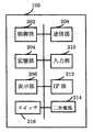
次に、図1に示されるスマートフォン105の内部構成について図2を参照して説明する。図2は、図1に示されるスマートフォン105の内部構成のブロック図である。 Next, the internal configuration of the
図2に示すように、スマートフォン105は、装置全体の制御を司る制御部(例えば、CPUなど)202と、本実施形態の充電プログラムその他のプログラムやデータ等を記憶する記憶部204とを備える。さらに、スマートフォン105は、例えばタッチパネルディスプレイにより構成され、画像や文字などを表示する表示部206と、近距離無線や有線ケーブル等により外部装置と通信を行う通信部208とを備える。 As illustrated in FIG. 2, the
また、スマートフォン105は、電源のオンオフを操作するボタンや音量を調整するボタンその他の操作をするためのボタンなどからなる入力部210を備える。また、スマートフォン105は、例えばmicroUSBにより充電器103などの外部機器と接続するIF部212を備える。 In addition, the
また、スマートフォン105は、装置全体に電力を供給する二次電池214を備える。この二次電池214は取り外しが可能であって良い。スマートフォン105の電源として本実施形態では二次電池214を用いるが、充電を行うことにより電気を蓄えて電池として使用できるものであれば、リチウム電池以外のものであっても良い。 In addition, the
また、スマートフォン105は、充電器103からの充電電力のオンオフを切り替えるためのスイッチ216を備える。 In addition, the
次に、図1に示される充電器103の内部構成について図3を参照して説明する。図3は、図1に示される充電器の内部構成のブロック図である。 Next, the internal configuration of the
図3に示されるように、充電器103は、コンセント101からの電流を整流する整流部301と、DC電圧を必要なデューティサイクルのAC電圧に変換するスイッチング部303と、AC電圧を変換するトランス部305と、スイッチング部303などを制御する制御部307とを備える。なお充電器103は、in側の端子から電力が入力し、out側端子から電力を出力する。 As shown in FIG. 3, the
また、充電器103は、スマートフォン105への充電端子に流れる電流を検出する電流検出部309と、スマートフォン105への充電端子に流れる電流のオンオフを切り替えるためのスイッチ311とを備える。 In addition, the
次に、図4を参照して図1に示される充電システムの接続状態について説明する。図4は、図1に示される充電システムの接続概略図である。なお、図4では、接続関係を説明するため、図1に示される充電システムの一部のみを図示している。 Next, the connection state of the charging system shown in FIG. 1 will be described with reference to FIG. FIG. 4 is a connection schematic diagram of the charging system shown in FIG. In FIG. 4, only a part of the charging system shown in FIG. 1 is illustrated in order to explain the connection relationship.
図4では、充電器103とスマートフォン105とが接続されている。充電器103は、スイッチ311と電流検出部309とが接続されている。また、充電器103からは、スマートフォン105と接続され、スマートフォンに電力を供給するための端子407a、407bが設けられている。 In FIG. 4, the
スマートフォン105は、スイッチ218や二次電池214の他、表示部や通信部などからなる負荷回路405が設けられている。負荷回路405は、スイッチ216と二次電池214とに接続されている。また、スマートフォン403には、充電器103の端子407aと端子407bとが接続されるコネクタ部403を備える。スマートフォン105は、充電器103の端子407aと端子407bと接続される端子409aと端子409bとを備える。 The
本実施形態では、充電器103の端子407aと端子407bとの間に異常部401が発生したとする。この異常部401は、例えば、端子407aと端子407bとの間の短絡や、端子407aや端子407bの漏電等がある。もちろん、本実施形態の異常部401として、短絡や漏電に限定されるものではなく、例えば水やほこりなどの異物混入などの任意の異常であっても良い。本実施形態では、この異常部401は、例えば、端子407aと端子407bとの間の短絡であるとして以下説明する。この異常部401は、抵抗と等価である。 In the present embodiment, it is assumed that an
充電器103とスマートフォン105とは、端子407a、407bなどを通じて相互に、制御信号などの情報をやりとりする。 The
次に、図1に示される充電システムの動作について、図4、図5、図6及び図7を参照して説明する。図5及び図6は、図1に示される充電システムの動作のタイミングチャートである。図5に示される場合は、充電システムに異常が発生していない場合のタイミングチャートであり、図6に示される場合は、充電システムに異常が発生している場合のタイミングチャートであり、図7は、図1に示される充電システムの動作のフローチャートである。 Next, the operation of the charging system shown in FIG. 1 will be described with reference to FIGS. 4, 5, 6 and 7. 5 and 6 are timing charts of the operation of the charging system shown in FIG. The case shown in FIG. 5 is a timing chart when no abnormality occurs in the charging system, and the case shown in FIG. 6 is a timing chart when abnormality occurs in the charging system. These are flowcharts of operation | movement of the charging system shown by FIG.
スマートフォン105の制御部202は、スマートフォン105と充電器103とが接続された際に、充電を開始させる(ステップS701)。 The
制御部202は、スイッチ216について、ON、OFFの動作をするよう制御する(ステップS703)。このON、OFFのそれぞれの回数は、スマートフォン105に充電器103に接続された後に一度だけとしても良いし、ON、OFFを複数回繰り返すとしても良い。ここで、制御部202は、スマートフォン105に充電器103が接続されていない初期状態においてスイッチ216をON状態にしておくものとする。もちろん、制御部202は、スイッチ216を初期状態においてOFF状態にしておくとしても良い。また、制御部202がスイッチ216をOFFする期間は短くてもよい。 The
次に、充電器103の制御部307は、電流検出部309により、スイッチ216がOFF状態の場合に、電流を検出したか否かを判断する(ステップS705)。 Next, the
次に、制御部307は、電流を検出した場合(ステップS705、Yes)、スイッチ311をOFFとし、充電を停止させる(ステップS707)。また、制御部307は、電流を検出しなかった場合(ステップS705、No)、スイッチ311のONを継続し、充電を継続し(ステップS711)、動作を終了する。 Next, when the current is detected (step S705, Yes), the
次に、制御部307は、充電を停止した後、スマートフォン105に電流を検出した旨を通知し(ステップS709)、動作を終了する。 Next, after stopping charging, the
次に図1に示される充電システムの動作についてさらに説明する。
1)正常時の動作
正常な状態であれば、スイッチ216をオフとすれば、充電中であっても電流検出部309が検出する電流がゼロとなる(図5における期間T1、T2)。制御部307は、この電流がゼロとなる期間T1,T2の検出により正常と判断する。Next, the operation of the charging system shown in FIG. 1 will be further described.
1) Normal operation When the
2)異常時の動作
異常時、例えば、異常部401の存在により本来の充電経路以外に電流が流れている場合、スイッチ216をオフにしても、端子407aと端子407bとの間には電流が流れ続けることになる。この場合、電流検出部309は、充電開始から一定期間が経っても電流を検出し、スイッチ216をオフとしている間でも電流を検出する(図6の期間T3)。制御部307は、正常であれば電流が検出されないはずの期間に電流が検出されると、異常と判定する。そして、制御部307は、異常と判定するとスイッチ311をオフにして充電動作(電流供給)を停止させる。2) Operation at the time of abnormality In the case of an abnormality, for example, when a current is flowing outside the original charging path due to the presence of the
このように、本実施形態の電子機器を用いた充電システムによれば、電流が検出されたか否かにより異常発生の有無を検知しているため、発熱検知の為の温度センサ等が不要となる。 As described above, according to the charging system using the electronic apparatus of the present embodiment, whether or not an abnormality has occurred is detected based on whether or not a current is detected, so that a temperature sensor or the like for detecting heat generation becomes unnecessary. .
そのため、本実施形態の電子機器を用いた充電システムによれば、センサを搭載する場合と比較して、様々な箇所での発熱を想定して複数のセンサデバイスを搭載する必要が無くなるためコスト的に有利となる。 Therefore, according to the charging system using the electronic apparatus of the present embodiment, it is not necessary to mount a plurality of sensor devices on the assumption of heat generation in various places, as compared with the case where a sensor is mounted. Is advantageous.
また、従来では、充電器103は、流れている電流が正常かどうかの判断ができず、異常時の充電停止が難しかったが、本実施形態の電子機器を用いた充電システムによれば、充電器103で異常状態を検出することが可能となる。そのため、充電器103が電流停止のスイッチなどの保護回路を発動させることが可能となる。 Conventionally, the
(変形例)
本発明の電子機器の一実施形態を適用した充電システムとしては、上記に限定されるものではない。本発明の電子機器の一実施形態を適用した充電システムの変形例について図8を参照して説明する。図8は、本発明の電子機器の一実施形態を適用した充電システムの変形例の接続概略図である。(Modification)
The charging system to which one embodiment of the electronic device of the present invention is applied is not limited to the above. A modification of the charging system to which an embodiment of the electronic apparatus of the invention is applied will be described with reference to FIG. FIG. 8 is a connection schematic diagram of a modification of the charging system to which one embodiment of the electronic apparatus of the invention is applied.
図8に示される充電システムでは、異常部801が、スマートフォン105のコネクタ403の内部に発生している。このような異常部801として、例えば、水や埃などの異物がコネクタ403内部に侵入した場合が考えられるが、本実施形態の異常部801としてはこのようなものに限定されず、適宜なもので有ってよい。図8に示される充電システムの動作は、図1から図7を参照して説明した充電システムと同様である。 In the charging system shown in FIG. 8, the
図8に示される充電システムであっても、図1から図7を参照して説明した充電システムと同様の効果を奏する。 Even the charging system shown in FIG. 8 has the same effect as the charging system described with reference to FIGS.
なお、上記実施形態に説明した場合に限定されるものではなく、様々な変形が可能である。例えば、制御部307は、正常であれば電流が検出されないはずの期間に電流が検出され異常と判定した場合に、充電動作における電流供給量を低減させるとしても良い。 In addition, it is not limited to the case where it demonstrated to the said embodiment, A various deformation | transformation is possible. For example, the
101 コンセント
103 充電器
105 スマートフォン
202 制御部
214 二次電池
216 スイッチ
309 電流検出部
311 スイッチ
401 異常部
801 異常部DESCRIPTION OF
Claims (3)
Translated fromJapanese前記二次電池を充電する電力が入力する第1の端子と、
前記二次電池と前記第1の端子との間の接続をオンオフする第1のスイッチと、
前記二次電池の充電を開始する場合に、所定期間、前記第1のスイッチをオフとする制御を行う第1の制御部と、を備える電子機器と接続される充電装置であって、
前記二次電池に電力を供給するための第2の端子と、
前記第2の端子に流れる電流を検出する検出部と、
前記二次電池と前記第2の端子との間の接続をオンオフする第2のスイッチと、
前記二次電池への充電が開始した場合に前記所定期間、前記検出部により電流が検出された場合は、前記第2のスイッチをオフとする制御を行う第2の制御部と、を備える充電装置。A secondary battery,
A first terminal to which power for charging the secondary battery is input;
A first switch for turning on and off a connection between the secondary battery and the first terminal;
A charging device connected to an electronic devicecomprising: a first control unit that controls to turn off the first switch for a predetermined period when charging of the secondary battery is started;
A second terminal for supplying power to the secondary battery;
A detection unit for detecting a current flowing through the second terminal;
A second switch for turning on and off the connection between the secondary battery and the second terminal;
A second control unit that performs control to turn off the second switch when current is detected by the detection unit for the predetermined period when charging to the secondary battery is started. apparatus.
二次電池への充電の開始を検出する工程、及び、Detecting the start of charging of the secondary battery; and
前記二次電池の充電を開始する場合に、所定期間、前記二次電池と接続された第1のスイッチをオフとする制御を行う工程、A step of performing control for turning off the first switch connected to the secondary battery for a predetermined period when charging of the secondary battery is started;
前記二次電池に充電電力を供給する第2の端子に流れる電流を検出する工程、及び、Detecting a current flowing in a second terminal for supplying charging power to the secondary battery; and
前記二次電池への充電が開始した場合に前記所定期間、前記検出する工程において電流が検出された場合は、前記二次電池と前記第2の端子との間の接続をオンオフする第2のスイッチをオフとする工程、を実行させる充電プログラム。When charging to the secondary battery starts, if a current is detected in the detecting step for the predetermined period, a second connection for turning on and off the connection between the secondary battery and the second terminal is performed. A charging program for executing a step of turning off the switch.
前記二次電池の充電を開始する場合に、所定期間、前記二次電池と接続された第1のスイッチをオフとする制御を行う工程と、A step of performing control to turn off the first switch connected to the secondary battery for a predetermined period when charging of the secondary battery is started;
前記二次電池に充電電力を供給する第2の端子に流れる電流を検出する工程と、Detecting a current flowing in a second terminal for supplying charging power to the secondary battery;
前記二次電池への充電が開始した場合に前記所定期間、前記検出する工程において電流が検出された場合は、前記二次電池と前記第2の端子との間の接続をオンオフする第2のスイッチをオフとする工程と、を備える充電方法。When charging to the secondary battery starts, if a current is detected in the detecting step for the predetermined period, a second connection for turning on and off the connection between the secondary battery and the second terminal is performed. And a step of turning off the switch.
Priority Applications (2)
| Application Number | Priority Date | Filing Date | Title |
|---|---|---|---|
| JP2015133188AJP6144727B2 (en) | 2015-07-02 | 2015-07-02 | Charging apparatus, charging program, and charging method |
| US15/193,161US20170005485A1 (en) | 2015-07-02 | 2016-06-27 | Electronic device, charging apparatus, charging program, and charging method |
Applications Claiming Priority (1)
| Application Number | Priority Date | Filing Date | Title |
|---|---|---|---|
| JP2015133188AJP6144727B2 (en) | 2015-07-02 | 2015-07-02 | Charging apparatus, charging program, and charging method |
Publications (2)
| Publication Number | Publication Date |
|---|---|
| JP2017017884A JP2017017884A (en) | 2017-01-19 |
| JP6144727B2true JP6144727B2 (en) | 2017-06-07 |
Family
ID=57684463
Family Applications (1)
| Application Number | Title | Priority Date | Filing Date |
|---|---|---|---|
| JP2015133188AExpired - Fee RelatedJP6144727B2 (en) | 2015-07-02 | 2015-07-02 | Charging apparatus, charging program, and charging method |
Country Status (2)
| Country | Link |
|---|---|
| US (1) | US20170005485A1 (en) |
| JP (1) | JP6144727B2 (en) |
Family Cites Families (21)
| Publication number | Priority date | Publication date | Assignee | Title |
|---|---|---|---|---|
| EP1032955A4 (en)* | 1998-07-27 | 2002-08-07 | Gnb Technologies | Apparatus and method for carrying out diagnostic tests on batteries and for rapidly charging batteries |
| US6462507B2 (en)* | 1998-08-07 | 2002-10-08 | Okc Products, Inc. | Apparatus and method for initial charging, self-starting, and operation of a power supply with an intermittent and/or variable energy source and a rechargeable energy storage device |
| GB2343797B (en)* | 1998-08-14 | 2003-07-16 | Milwaukee Electric Tool Corp | Battery charger |
| US7336054B2 (en)* | 1998-08-14 | 2008-02-26 | Milwaukee Electric Tool Corporation | Apparatus and method of activating a microcontroller |
| US6160389A (en)* | 1999-08-27 | 2000-12-12 | Black & Decker Inc. | Battery charger with low heat dissipation |
| JP2001178011A (en)* | 1999-12-10 | 2001-06-29 | Toshiba Battery Co Ltd | Secondary battery device |
| TW200623576A (en)* | 2004-12-17 | 2006-07-01 | Benq Corp | An electronic device |
| US7365525B2 (en)* | 2005-02-08 | 2008-04-29 | Linear Technology Corporation | Protection for switched step up/step down regulators |
| US7952330B2 (en)* | 2005-04-20 | 2011-05-31 | Panasonic Corporation | Secondary battery protection circuit, battery pack and thermosensitive protection switch device |
| US7489106B1 (en)* | 2006-03-31 | 2009-02-10 | Victor Tikhonov | Battery optimization system and method of use |
| JP2008061381A (en)* | 2006-08-31 | 2008-03-13 | Toshiba Corp | Charging system and charging method |
| US7990108B2 (en)* | 2007-05-14 | 2011-08-02 | Atmel Corporation | Charge detector |
| JP4503636B2 (en)* | 2007-08-28 | 2010-07-14 | レノボ・シンガポール・プライベート・リミテッド | Battery pack and charging method |
| US9314261B2 (en)* | 2007-12-03 | 2016-04-19 | Covidien Ag | Battery-powered hand-held ultrasonic surgical cautery cutting device |
| US8143862B2 (en)* | 2009-03-12 | 2012-03-27 | 02Micro Inc. | Circuits and methods for battery charging |
| JP5292155B2 (en)* | 2009-03-27 | 2013-09-18 | Tdkラムダ株式会社 | Power supply control device, power supply device, and power supply control method |
| JP2010233431A (en)* | 2009-03-30 | 2010-10-14 | Saxa Inc | Charging control circuit |
| US8629649B2 (en)* | 2011-07-14 | 2014-01-14 | O2Micro International, Ltd. | Battery charging apparatus with a common control loop for a low drop-out voltage regulator and a boost regulator |
| WO2013108155A2 (en)* | 2012-01-19 | 2013-07-25 | Koninklijke Philips N.V. | Power supply device |
| JP5869447B2 (en)* | 2012-08-21 | 2016-02-24 | 株式会社マキタ | Charger |
| JP5723938B2 (en)* | 2013-06-21 | 2015-05-27 | パナソニック インテレクチュアル プロパティ コーポレーション オブアメリカPanasonic Intellectual Property Corporation of America | Electronic equipment and electronic equipment system |
- 2015
- 2015-07-02JPJP2015133188Apatent/JP6144727B2/ennot_activeExpired - Fee Related
- 2016
- 2016-06-27USUS15/193,161patent/US20170005485A1/ennot_activeAbandoned
Also Published As
| Publication number | Publication date |
|---|---|
| JP2017017884A (en) | 2017-01-19 |
| US20170005485A1 (en) | 2017-01-05 |
Similar Documents
| Publication | Publication Date | Title |
|---|---|---|
| TWI547058B (en) | Charger, battery module, method and system for identifying and monitoring a charger | |
| US9973009B2 (en) | Wireless power transmisson apparatus and wireless power transmisson method | |
| TWI474532B (en) | Systems, controllers and methods for battery controlling | |
| JP6231883B2 (en) | Electronic device and electronic device charging system | |
| JP4855871B2 (en) | Charger | |
| CN102005624A (en) | Method for heating a rechargeable battery, charger, and accessory element | |
| JP2015040799A (en) | Power supply circuit device, curent measurement device, power monitoring system, and method for protecting power supply circuit device | |
| US10181741B2 (en) | Storage battery device | |
| JP6040922B2 (en) | Charging system | |
| EP3564981B1 (en) | Relay device | |
| JP2005245078A (en) | Electromagnetic induction charging circuit | |
| JP6144727B2 (en) | Charging apparatus, charging program, and charging method | |
| JP2024096403A (en) | Mobile devices | |
| JP2014135895A (en) | Charge control system and method | |
| WO2015112172A1 (en) | Charge algorithm for battery propelled elevator | |
| JP5816814B2 (en) | Charger | |
| JP6883852B2 (en) | Power supply unit equipped with lithium ion secondary battery and its control method | |
| JP7139599B2 (en) | charging controller | |
| JP6485750B2 (en) | Power storage system, control device, operation method | |
| CN106654408A (en) | User equipment, battery, load end and power supply method | |
| JP2015082874A (en) | On-vehicle charging system | |
| JP6583782B2 (en) | Power storage system, control device, operation method | |
| JP6417117B2 (en) | Control device, control method, and control program | |
| JP5736016B2 (en) | Electronic device, charger and electronic device system | |
| JP2013208006A (en) | Power control unit |
Legal Events
| Date | Code | Title | Description |
|---|---|---|---|
| A131 | Notification of reasons for refusal | Free format text:JAPANESE INTERMEDIATE CODE: A131 Effective date:20161018 | |
| A521 | Written amendment | Free format text:JAPANESE INTERMEDIATE CODE: A523 Effective date:20161207 | |
| TRDD | Decision of grant or rejection written | ||
| A01 | Written decision to grant a patent or to grant a registration (utility model) | Free format text:JAPANESE INTERMEDIATE CODE: A01 Effective date:20170411 | |
| A61 | First payment of annual fees (during grant procedure) | Free format text:JAPANESE INTERMEDIATE CODE: A61 Effective date:20170511 | |
| R150 | Certificate of patent or registration of utility model | Ref document number:6144727 Country of ref document:JP Free format text:JAPANESE INTERMEDIATE CODE: R150 | |
| LAPS | Cancellation because of no payment of annual fees |