JP6143820B2 - Terminal device - Google Patents
Terminal deviceDownload PDFInfo
- Publication number
- JP6143820B2 JP6143820B2JP2015174735AJP2015174735AJP6143820B2JP 6143820 B2JP6143820 B2JP 6143820B2JP 2015174735 AJP2015174735 AJP 2015174735AJP 2015174735 AJP2015174735 AJP 2015174735AJP 6143820 B2JP6143820 B2JP 6143820B2
- Authority
- JP
- Japan
- Prior art keywords
- terminal device
- home screen
- usage mode
- icon
- application
- Prior art date
- Legal status (The legal status is an assumption and is not a legal conclusion. Google has not performed a legal analysis and makes no representation as to the accuracy of the status listed.)
- Active
Links
Images


Landscapes
- User Interface Of Digital Computer (AREA)
Description
Translated fromJapanese本発明は、端末装置に関する。 The present invention relates to a terminal device.
従来、アプリケーションを起動するためのアイコンを画面上に配置する技術として、例えば特許文献1が知られている。この従来技術では、利用者がコンテンツ情報提供事業者の識別情報をアイコン生成装置に送信しコンテンツ情報を取得した後、そのコンテンツ情報にかかるWebサイトにアクセスするためのアイコン情報を受け取り、それに基づいてアイコンを画面上に配置する。 Conventionally, for example,
しかし、上述した従来のアイコン配置技術では、表示されるアイコンの構成を変更することまではできず、利用者の利便性を向上することが困難である場合があった。 However, with the conventional icon arrangement technique described above, it is not possible to change the configuration of displayed icons, and it may be difficult to improve the convenience for the user.
本発明は、このような事情を考慮してなされたものであり、端末装置に表示されるアイコンの構成を変更することにより、利用者の利便性を向上することができる端末装置を提供することを課題とする。 The present invention has been made in consideration of such circumstances, and provides a terminal device that can improve the convenience of the user by changing the configuration of icons displayed on the terminal device. Is an issue.
(1)本発明の一態様は、ホーム画面を表示する表示部と、端末装置の利用態様を示す利用態様情報を取得する利用態様取得部と、端末装置のホーム画面の画面構成情報が、端末装置の利用態様毎に記憶される記憶部から、前記利用態様取得部が取得する前記利用態様情報に応じた前記画面構成情報を取得する画面構成取得部と、アプリケーションのアイコンのホーム画面上の位置を、前記画面構成取得部が取得する前記画面構成情報が示す位置にしてホーム画面を構成するホーム画面構成部とを備える端末装置である。(1) According to one aspect of the present invention, a display unit that displays a home screen, a usage mode acquisition unit that acquires usage mode information indicating a usage mode of a terminal device, and screen configuration information of the home screen of the terminal device A screen configuration acquisition unit that acquires the screen configuration information according to the usage mode information acquired by the usage mode acquisition unit from a storage unit that is stored for each usage mode of the device, and a position on the home screen of the application icon Is a terminal device that includes a home screen configuration unit that configures a home screen at a position indicated by the screen configuration information acquired by the screen configuration acquisition unit.
(2)本発明の一態様は、上記(1)の端末装置において、端末装置にインストールされているアプリケーションのアイコンの前記ホーム画面上の位置を示すアイコン位置情報を含む記録データであって、前記アイコン位置情報が互いに異なる複数の記録データのうちから、ある記録データの選択操作を受付ける操作受付部を更に備え、前記ホーム画面構成部は、前記複数の記録データのうち、前記操作受付部が受け付けた前記選択操作が示す記録データに含まれる前記アイコン位置情報に基づいて、アプリケーションのアイコンを前記ホーム画面上の位置に配置する端末装置である。(2) One aspect of the present invention is the recording data including icon position information indicating a position on the home screen of the icon of the application installed in the terminal device in the terminal device of (1) above, An operation accepting unit that accepts a selection operation for selecting certain recording data from among a plurality of recording data having different icon position information, and the home screen configuration unit accepts the operation accepting unit among the plurality of recording data. The terminal device arranges an application icon at a position on the home screen based on the icon position information included in the recording data indicated by the selection operation.
(3)本発明の一態様は、上記(1)又は(2)のいずれかの端末装置において、前記利用態様情報とは、自端末装置と他の端末装置との間の通信において自端末装置を示す識別情報に基づく情報であり、前記利用態様取得部は、前記識別情報に基づく前記利用態様情報を取得する端末装置である。(3) One aspect of the present invention is the terminal device according to any one of the above (1) and (2), wherein the usage mode information refers to the own terminal device in communication between the own terminal device and another terminal device. The usage mode acquisition unit is a terminal device that acquires the usage mode information based on the identification information.
(4)本発明の一態様は、上記(1)から(3)のいずれかの端末装置において、前記利用態様情報とは、自端末装置の位置を示す位置情報に基づく情報であり、自端末装置の位置に基づいて、端末装置の利用態様を判定する利用態様判定部を更に備え、前記利用態様取得部は、前記利用態様判定部が判定した利用態様を示す利用態様情報を取得する端末装置である。(4) One aspect of the present invention is the terminal device according to any one of (1) to (3) above, wherein the usage mode information is information based on position information indicating a position of the terminal device. A terminal device that further includes a usage mode determination unit that determines a usage mode of the terminal device based on a position of the device, wherein the usage mode acquisition unit acquires usage mode information indicating the usage mode determined by the usage mode determination unit. It is.
(5)本発明の一態様は、上記(1)から(4)のいずれかの端末装置において、前記ホーム画面構成部は、前記利用態様のうちの第1の利用態様において、アプリケーションが利用可能であるか否かに基づいて、当該アプリケーションのアイコンの表示態様を変更してホーム画面を構成する端末装置である。(5) According to one aspect of the present invention, in the terminal device according to any one of (1) to (4), the home screen configuration unit can use an application in the first usage mode of the usage modes. This is a terminal device that configures the home screen by changing the display mode of the icon of the application based on whether or not.
(6)本発明の一態様は、上記(1)から(5)のいずれかの端末装置において、前記表示態様には、前記アイコンの画像の透過度、前記アイコンの画像の形状、及び前記アイコンの画像の色が含まれる端末装置である。(6) According to one aspect of the present invention, in the terminal device according to any one of (1) to (5), the display mode includes the transparency of the icon image, the shape of the icon image, and the icon. Is a terminal device including the color of the image.
本発明によれば、端末装置に表示されるアイコンの配置を変更することにより、利用者の利便性を向上する効果が得られる。 ADVANTAGE OF THE INVENTION According to this invention, the effect which improves a user's convenience is acquired by changing arrangement | positioning of the icon displayed on a terminal device.
以下、図面を参照し、本発明の実施形態について説明する。
図1は、本発明の一実施形態に係る通信システムの例を示す構成図である。図1において、端末装置1は、無線通信ネットワーク2を介して他の装置と通信を行う。端末装置1は、無線通信ネットワーク2を介して、無線通信ネットワーク2に接続される利用者情報管理サーバ3及び第1アプリケーション提供サーバ4にアクセスする。無線通信ネットワーク2は通信回線を介してインターネット6と接続する。端末装置1は、無線通信ネットワーク2を介して、インターネット6に接続される第2アプリケーション提供サーバ5にアクセスする。Hereinafter, embodiments of the present invention will be described with reference to the drawings.
FIG. 1 is a configuration diagram showing an example of a communication system according to an embodiment of the present invention. In FIG. 1, a
なお、利用者情報管理サーバ3、第1アプリケーション提供サーバ4及び第2アプリケーション提供サーバ5は、端末装置1から無線通信ネットワーク2を介してアクセスすることができればよく、上記の図1の構成に限定されない。例えば、利用者情報管理サーバ3、第1アプリケーション提供サーバ4及び第2アプリケーション提供サーバ5のうち、全てが無線通信ネットワーク2に接続されていてもよく、又は、全てがインターネット6に接続されていてもよく、又は、いずれか一つ若しくは二つが無線通信ネットワーク2に接続され残りがインターネット6に接続されていてもよい。 The user
図2は、本発明の一実施形態に係る端末装置1を示す構成図である。図1において、端末装置1は、制御部11と記憶部12と通信部13と操作部14と表示部15と接続部16を備える。これら各部はデータを交換できるように構成される。制御部11は、メモリ及びCPU(中央処理装置)を備え、制御部11の機能を実現するためのコンピュータプログラムをCPUが実行することによりその機能を実現させる。 FIG. 2 is a configuration diagram showing the
記憶部12は、制御部11のCPUで実行されるコンピュータプログラム及び各種のデータを記憶する。記憶部12としては、例えば、ハードディスク装置、フラッシュメモリ等の不揮発性のメモリ、DRAM(Dynamic Random Access Memory)等の揮発性のメモリなどが利用可能である。 The
通信部13は、無線通信ネットワーク2を介して、端末装置1の外部の装置と通信を行う。操作部14は、入力デバイスから構成され、利用者の操作に応じたデータ入力を行う。入力デバイスとして、例えば、キーボード、テンキー、マウス、操作ボタンなどが挙げられる。表示部15は、液晶表示装置等の表示デバイスから構成され、データ表示を行う。なお、表示部15として、データ入力とデータ表示の両方が可能なタッチパネルを備えてもよい。 The
接続部16は、記録媒体17と接続する。接続部16は、記録媒体17を着脱可能に構成される。接続部16は、自己に接続された記録媒体17からデータを読み出す。また、接続部16は、自己に接続された記録媒体17に対してデータを書き込む。記録媒体17として、例えば、SDカード等の着脱可能なメモリカードなどが利用可能である。 The
端末装置1としては、例えば、スマートフォン等の携帯通信端末装置、タブレット型のコンピュータ(タブレットPC)等の携帯型のパーソナルコンピュータなどであってもよい。 The
図3は、図2に示す制御部11の機能構成図である。図3において、制御部11は、ホーム画面変更部20、記録データ記憶制御部23、アプリケーション起動部24、アプリケーションインストール部25、表示制御部26、利用態様取得部27、利用態様判定部28などを備える。ホーム画面変更部20は、ホーム画面構成部21及び記録データ取得部22を備える。これら制御部11の機能は、記憶部12に記憶されているコンピュータプログラムを制御部11のCPUが実行することにより実現される。 FIG. 3 is a functional configuration diagram of the
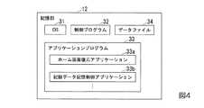
図4は、図2に示す記憶部12の記憶構成例を示す図である。図4において、記憶部12は、OS(Operating System:オペレーティングシステム)31と制御プログラム32とアプリケーションプログラム33とデータファイル34を記憶する。OS31と制御プログラム32とアプリケーションプログラム33は、制御部11のCPUで実行されるコンピュータプログラムである。アプリケーションプログラム33として、ホーム画面変更アプリケーション33a及び記録データ記憶制御アプリケーション33bなどがある。また、アプリケーションプログラム33として、例えば、SNS(Social Networking Service)アプリケーション、電子メールアプリケーション、Web(ウェブ)ブラウザアプリケーション、画像管理アプリケーション、ゲームアプリケーションなどのコンピュータプログラムが挙げられる。 FIG. 4 is a diagram illustrating a storage configuration example of the
データファイル34は複数あってもよい。データファイル34としては、例えば、テキストデータファイル、音声データファイル、画像(静止画像又は動画像)データファイル、個人データファイル、URL(Uniform Resource Locator)データファイルなどが挙げられる。 There may be a plurality of data files 34. Examples of the data file 34 include a text data file, an audio data file, an image (still image or moving image) data file, a personal data file, and a URL (Uniform Resource Locator) data file.
次に、図5等を参照して、本実施形態に係る端末装置1の動作を説明する。 Next, with reference to FIG. 5 etc., operation | movement of the
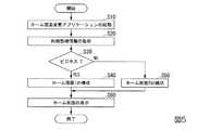
はじめに図5を参照して、本実施形態の端末装置1のホーム画面変更に係る動作の全体の流れを説明する。図5は、本実施形態に係るホーム画面変更方法のフローチャートである。 First, with reference to FIG. 5, the overall flow of the operation related to the home screen change of the
(ステップS10)アプリケーション起動部24が、ホーム画面変更アプリケーション33aを起動する。ホーム画面変更アプリケーション33aが起動されて制御部11のCPUにより実行されることにより、ホーム画面変更部20の機能が実現される。アプリケーション起動部24がホーム画面変更アプリケーション33aを起動するタイミングは、予め定めることができる。例えば、アプリケーション起動部24は、端末装置1がスリープ状態から復帰するタイミングで、ホーム画面変更アプリケーション33aを起動してもよい。端末装置1のスリープ状態からの復帰は、利用者が端末装置1を使い始める時などに実行される。なお、アプリケーション起動部24は、利用者の所定の操作に応じて、ホーム画面変更アプリケーション33aを起動してもよい。また、アプリケーション起動部24は、端末装置1の位置が変化したことに応じて、ホーム画面変更アプリケーション33aを起動してもよい。端末装置1の位置は、GPS(Global Positioning System)や、無線通信の電波を受信することで特定することができる。(Step S10) The
(ステップS20)利用態様取得部27が、端末装置1の利用態様を示す利用態様情報を取得する。端末装置1の利用態様には、例えば、ビジネスでの利用や、プライベートでの利用がある。
(ステップS30)利用態様判定部28が、利用態様取得部27が取得した利用態様情報に基づいて、端末装置1の利用態様を判定する。利用態様判定部28は、種々の方法により端末装置1の利用態様を判定可能である。(Step S20) The usage
(Step S30) The usage
一例として、端末装置1が2つ以上の端末識別情報を有している場合がある。ここで、端末識別情報とは、例えば、電話番号やMACアドレス、利用者IDなどである。端末装置1の2つの端末識別情報のうち、一方の端末識別情報がビジネスでの利用に用いられ、他方の端末識別情報がプライベートでの利用に用いられている場合がある。この場合には、利用態様取得部27は、いずれの端末識別情報が利用されているかを示す情報を、端末装置1の利用態様として取得する。利用態様判定部28は、利用されている端末識別情報がビジネス用であるかプライベート用であるかによって、端末装置1の利用態様を判定する。 As an example, the
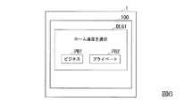
他の一例として、利用態様判定部28が、利用者の操作に基づいて、端末装置1の利用態様を判定する場合について、図6を参照して説明する。図6は、端末装置1の表示画面100に表示される選択画面DLG1の一例を示す図である。 As another example, the case where the usage
図6において、端末装置1は、表示画面100を備える。表示画面100は、例えばタッチパネルの表示画面である。端末装置1の表示画面100には、選択画面DLG1が表示される。選択画面DLG1には、ビジネスを示すボタン画像PB1と、プライベートを示すボタン画像PB2とが表示される。この一例の場合、利用態様取得部27は、ボタン画像PB1及びボタン画像PB2のうち、利用者が操作したボタン画像を示す操作情報を取得する。 In FIG. 6, the
ステップS30の結果、ビジネスでの利用と判定した場合にはステップS40に進む。一方、ステップS30の結果、プライベートでの利用と判定した場合にはステップS50に進む。 As a result of step S30, when it is determined that it is used for business, the process proceeds to step S40. On the other hand, if it is determined in step S30 that the private use is made, the process proceeds to step S50.
ここで、図7から図9を参照してホーム画面構成情報記録データを説明する。図7は、本実施形態に係るホーム画面構成情報記録データ40aの構成例を示す図表である。ホーム画面構成情報記録データ40aは、端末装置1のホーム画面のうち、ビジネス用の画面構成情報の記録データである。図8は、本実施形態に係るホーム画面構成情報記録データ40bの構成例を示す図表である。ホーム画面構成情報記録データ40bは、端末装置1のホーム画面のうち、プライベート用の画面構成情報の記録データである。以下の説明において、ホーム画面構成情報記録データ40aと、ホーム画面構成情報記録データ40bとを区別しない場合には、ホーム画面構成情報記録データ40と総称する。 Here, the home screen configuration information recording data will be described with reference to FIGS. FIG. 7 is a chart showing a configuration example of the home screen configuration information recording data 40a according to the present embodiment. The home screen configuration information recording data 40 a is recording data of business screen configuration information among the home screens of the
図9は、本実施形態に係るホーム画面構成情報記録データ40を説明するための図である。端末装置1の表示画面100には、ホーム画面が表示される。ビジネス用のホーム画面110aを図9(A)に示す。プライベート用のホーム画面110bを図9(B)に示す。以下の説明において、ビジネス用のホーム画面110aと、プライベート用のホーム画面110bとを区別しない場合には、ホーム画面110と総称する。
ホーム画面110は、一つ又は複数の画面から構成される。ホーム画面110が複数の画面から構成される場合、ホーム画面110を構成する各画面は、画面スクロールによって、表示画面100に表示される。FIG. 9 is a diagram for explaining the home screen configuration information recording data 40 according to the present embodiment. A home screen is displayed on the
The home screen 110 is composed of one or more screens. When the home screen 110 is composed of a plurality of screens, each screen constituting the home screen 110 is displayed on the
ホーム画面構成情報記録データ40は、端末装置1の各アプリケーションのアイコンGのホーム画面110における位置を示すアイコン位置情報を含む。また、ホーム画面構成情報記録データ40は、アイコンGの画像を示すアイコン画像データを含む。図9において、ホーム画面構成情報記録データ40は、アイコンG毎に、アイコンGのアイコン位置情報と、アイコンGの画像データ(アイコン画像データ)と、アイコンGに対応付けられているアプリケーションの識別情報(アプリケーションID)を有する。 The home screen configuration information recording data 40 includes icon position information indicating the position on the home screen 110 of the icon G of each application of the
ビジネス用のホーム画面110aは、ホーム画面構成情報記録データ40aに含まれるアイコン位置情報及びアイコン画像データに基づいて構成される。プライベート用のホーム画面110bは、ホーム画面構成情報記録データ40bに含まれるアイコン位置情報及びアイコン画像データに基づいて構成される。 The
端末装置1の各アプリケーションには、ビジネスやプライベートを問わず利用できるものと、ビジネスの利用には向かないものと、プライベートの利用には向かないものとがある。例えば、WWWブラウザなどのアプリケーションは、ビジネスやプライベートを問わず利用できる場合がある。また、SNS(social networking service)に対する情報投稿や、カメラなどのアプリケーションは、企業における就業時間内または執務室内での使用が禁止されている場合がある。また、企業内のイントラネット接続用などのアプリケーションは、プライベートで利用する機会がほとんどない。
ここで、ホーム画面110には、利用頻度が高いアプリケーションのアイコンGが配置される。しかしながら、ビジネスでの利用頻度が高いアプリケーションのアイコンGと、プライベートでの利用頻度が高いアプリケーションのアイコンGとが、同時にホーム画面110に配置されると、ホーム画面110が煩雑になる。
端末装置1は、利用態様毎にホーム画面110を切り換えるため、ホーム画面110が煩雑になる程度を低減することができる。Each application of the
Here, on the home screen 110, an icon G of an application that is frequently used is arranged. However, if the application icon G having a high usage frequency in business and the application icon G having a high usage frequency in private are simultaneously arranged on the home screen 110, the home screen 110 becomes complicated.
Since the
一例として、アプリケーションID_5、及びアプリケーションID_6が、プライベートでの利用に向かないアプリケーションである。アプリケーションID_7、及びアプリケーションID_8が、ビジネスでの利用に向かないアプリケーションである。この例の場合、ビジネスで利用されるホーム画面110aにおいては、アプリケーションID_7、及びアプリケーションID_8のアイコンGは、他のアイコンGと判別ができるように表示される。例えば、ホーム画面110aにおいては、アプリケーションID_7、及びアプリケーションID_8のアイコンGは、透過度や形状、色が他のアイコンGと判別できるように変更される。具体的には、ホーム画面110aにおいては、アプリケーションID_7のアイコンGは、アイコン画像データの画像7aに基づいて表示される。また、ホーム画面110aにおいては、アプリケーションID_8のアイコンGは、アイコン画像データの画像8aに基づいて表示される。ここで、画像7aが、上述した画像7を半透明にした画像である場合には、アプリケーションID_7について、ホーム画面110aにおいては、半透明のアイコンGが表示される。また、画像8aが、上述した画像8を半透明にした画像である場合には、アプリケーションID_8について、ホーム画面110aにおいては、半透明のアイコンGが表示される。
また、プライベートで利用されるホーム画面110bにおいては、アプリケーションID_5、及びアプリケーションID_6のアイコンGは、他のアイコンGと判別ができるように表示される。例えば、ホーム画面110bにおいては、アプリケーションID_5、及びアプリケーションID_6のアイコンGは、透過度や形状、色が他のアイコンGと判別できるように変更される。具体的には、ホーム画面110bにおいては、アプリケーションID_5のアイコンGは、アイコン画像データの画像5aに基づいて表示される。また、ホーム画面110aにおいては、アプリケーションID_6のアイコンGは、アイコン画像データの画像6aに基づいて表示される。ここで、画像5aが、上述した画像5を半透明にした画像である場合には、アプリケーションID_5について、ホーム画面110bにおいては、半透明のアイコンGが表示される。また、画像6aが、上述した画像6を半透明にした画像である場合には、アプリケーションID_6について、ホーム画面110bにおいては、半透明のアイコンGが表示される。
なお、図9(A)及び図9(B)においては、半透明のアイコンGを網掛けによって示す。As an example, application ID_5 and application ID_6 are applications that are not suitable for private use. Application ID_7 and application ID_8 are applications that are not suitable for business use. In the case of this example, on the
On the private home screen 110b, the icons G of the application ID_5 and the application ID_6 are displayed so that they can be distinguished from other icons G. For example, on the home screen 110b, the icons G of the application ID_5 and the application ID_6 are changed so that the transparency, shape, and color can be distinguished from other icons G. Specifically, on the home screen 110b, the icon G of the application ID_5 is displayed based on the image 5a of icon image data. On the
9A and 9B, the translucent icon G is indicated by shading.
すなわち、端末装置1は、利用できないアプリケーションのアイコンGの表示態様と、利用可能なアプリケーションのアイコンGの表示態様とを変えてホーム画面110を構成する。このように構成することにより、端末装置1は、ある利用態様では利用できないアプリケーションであっても、他の利用態様では利用可能なアプリケーションであることを、利用者に示すことができる。つまり、端末装置1は、利用者の利便性を向上することができる。 That is, the
なお、ホーム画面構成情報記録データ40は、自動的に又は端末装置1の利用者の所定の操作に応じて記録される。端末装置1においては、記録データ記憶制御部23が、端末装置1のホーム画面の画面構成情報を記録する機能を有する。記録データ記憶制御部23は、所定のタイミングで端末装置1のホーム画面の画面構成情報を記録する。例えば、記録データ記憶制御部23は、定期的に端末装置1のホーム画面の画面構成情報を記録してもよい。なお、記録データ記憶制御部23は、利用者の所定の操作に応じて、端末装置1のホーム画面の画面構成情報を記録してもよい。 The home screen configuration information recording data 40 is recorded automatically or in response to a predetermined operation of the user of the
説明を図5に戻す。
(ステップS40)記録データ取得部22が、図7に例示されるホーム画面構成情報記録データ40aを取得する。ホーム画面構成部21は、記録データ取得部22が取得したホーム画面構成情報記録データ40aを使用して、端末装置1のホーム画面110aを構成する。
(ステップS50)記録データ取得部22が、図8に例示されるホーム画面構成情報記録データ40bを取得する。ホーム画面構成部21は、記録データ取得部22が取得したホーム画面構成情報記録データ40bを使用して、端末装置1のホーム画面110bを構成する。
なお、記録データ取得部22とは、画面構成取得部の一例である。Returning to FIG.
(Step S40) The recording
(Step S50) The recording
The recording
ホーム画面構成情報記録データ40は、利用者情報管理サーバ3に格納されたり、又は、記録媒体17に格納されたりする。利用者情報管理サーバ3は、利用者識別情報(利用者ID)に関連付けてホーム画面構成情報記録データ40を格納する。端末装置1の記録データ取得部22は、利用者情報管理サーバ3からホーム画面構成情報記録データ40を取得する場合、利用者情報管理サーバ3へ利用者IDを送信し、該利用者IDに関連付けられているホーム画面構成情報記録データ40を利用者情報管理サーバ3から受信する。記録データ取得部22が利用者情報管理サーバ3へ送信する利用者IDは、予め、端末装置1に設定されたり、又は、記録媒体17に格納されたりする。なお、記録データ取得部22が利用者情報管理サーバ3へ送信する利用者IDは、ホーム画面構成情報記録データ40を取得する際に、利用者が入力してもよい。 The home screen configuration information recording data 40 is stored in the user
また、記録データ取得部22は、端末装置1の接続部16に接続された記録媒体17からホーム画面構成情報記録データ40を取得する場合、接続部16により該記録媒体17からホーム画面構成情報記録データ40を読み出す。 Further, when the recording
(ステップS60)端末装置1の表示部15は、ホーム画面構成部21が構成したホーム画面を自己の表示画面に表示する。(Step S60) The
[変形例]
利用態様判定部28による端末装置1の利用態様の判定の変形例について図10及び図11を参照して説明する。図10は、利用態様判定部28による端末装置1の利用態様の判定の第1の変形例を示す図である。この変形例においては、利用態様判定部28は、端末装置1の位置に基づいて、端末装置1の利用態様を判定する。端末装置1の位置は、GPS(Global Positioning System)や、無線通信の電波を受信することで特定することができる。具体的には、図10に示すように、端末装置1が、利用者の自宅HMの周辺の領域AR1にある場合には、利用態様判定部28は、プライベートでの利用と判定する。また、端末装置1が、利用者の勤務先の建物BLの周辺の領域AR2にある場合には、利用態様判定部28は、ビジネスでの利用と判定する。
なお、建物BLには、近距離無線通信設備が設置されていることがある。この近距離無線通信設備が建物BLの部屋ごとに設置されている場合には、利用態様判定部28は、端末装置1がどの近距離無線通信設備から電波を受信しているかによって、利用態様を判定してもよい。例えば、利用者の自席がある部屋に設置されている近距離無線通信設備から電波を受信している場合には、利用態様判定部28は、利用態様をビジネス(自席)での利用と判定する。また、会議室に設置されている近距離無線通信設備から電波を受信している場合には、利用態様判定部28は、利用態様をビジネス(会議室)での利用と判定する。
このように構成することによっても、端末装置1は、利用態様毎にホーム画面110を切り換えるため、ホーム画面110が煩雑になる程度を低減することができる。また、端末装置1は、より細かく利用態様を判定することができるため、利用態様に即したアイコンGをホーム画面110に配置することができ、利便性を向上することができる。[Modification]
A modified example of the determination of the usage mode of the
Note that short-range wireless communication facilities may be installed in the building BL. When this short-range wireless communication facility is installed for each room of the building BL, the usage
Also by configuring in this way, the
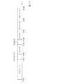
図11は、利用態様判定部28による端末装置1の利用態様の判定の第2の変形例を示す図である。この変形例においては、利用態様判定部28は、時刻に基づいて、端末装置1の利用態様を判定する。具体的には、図11に示すように、時刻0:00から時刻9:00及び時刻17:00から時刻24:00の場合には、利用態様判定部28は、プライベートでの利用と判定する。また、時刻9:00から時刻17:00の場合には、利用態様判定部28は、ビジネスでの利用と判定する。
また、利用態様判定部28は、時刻をさらに細分化して判定してもよい。例えば、時刻8:00から時刻9:00が通勤時間帯である場合には、通勤時間帯に適するアプリケーションのアイコンGを配置すれば、利便性がより向上する。通勤時間帯に適するアプリケーションとは、例えば、新聞閲覧アプリケーションや、英会話などの学習アプリケーションである。この場合には、利用態様判定部28は、時刻0:00から時刻8:00までの利用態様をプライベート1として判定し、時刻8:00から時刻9:00までの利用態様をプライベート2として判定する。
また、例えば、時刻12:00から時刻13:00が昼休みの時間帯である場合には、昼休みの時間帯に適するアプリケーションのアイコンGを配置すれば、利便性がより向上する。昼休みの時間帯に適するアプリケーションとは、例えば、飲食店舗を検索するアプリケーションである。この場合には、利用態様判定部28は、時刻9:00から時刻12:00までの利用態様をビジネス1として判定し、時刻12:00から時刻13:00までの利用態様をビジネス2として判定する。FIG. 11 is a diagram illustrating a second modification of the usage mode determination of the
Moreover, the utilization
Further, for example, when the time from 12:00 to 13:00 is a lunch break time zone, if an application icon G suitable for the lunch break time zone is arranged, the convenience is further improved. The application suitable for the lunch break time zone is, for example, an application for searching for restaurants. In this case, the usage
以上、本発明の実施形態について図面を参照して詳述してきたが、具体的な構成はこの実施形態に限られるものではなく、本発明の要旨を逸脱しない範囲の設計変更等も含まれる。 As mentioned above, although embodiment of this invention was explained in full detail with reference to drawings, the specific structure is not restricted to this embodiment, The design change etc. of the range which does not deviate from the summary of this invention are included.
例えば、上述の実施形態では、端末装置1は、無線通信ネットワーク2を介して他の装置と通信を行うが、これに限定されない。端末装置1は、無線又は有線の通信ネットワークを介して他の装置と通信を行うものであってもよい。この場合、端末装置1は、無線又は有線の通信ネットワークを介して、利用者情報管理サーバ3、第1アプリケーション提供サーバ4及び第2アプリケーション提供サーバ5にアクセスする。 For example, in the above-described embodiment, the
また、上述の実施形態では、ホーム画面構成情報記録データ40はアイコン画像データを含むが、アイコン画像データをホーム画面構成情報記録データ40に含めず、端末装置1がアプリケーションIDに基づいてアイコン画像データを取得してもよい。例えば、端末装置1は、第1アプリケーション提供サーバ4又は第2アプリケーション提供サーバ5からアイコン画像データを取得してもよい。又は、端末装置1が、予め、アイコン画像データを初期データファイルに保持してもよい。 In the above-described embodiment, the home screen configuration information recording data 40 includes icon image data. However, the icon image data is not included in the home screen configuration information recording data 40, and the
また、上述した端末装置1の機能を実現するためのコンピュータプログラムをコンピュータ読み取り可能な記録媒体に記録して、この記録媒体に記録されたプログラムをコンピュータシステムに読み込ませ、実行するようにしてもよい。なお、ここでいう「コンピュータシステム」とは、OSや周辺機器等のハードウェアを含むものであってもよい。
また、「コンピュータ読み取り可能な記録媒体」とは、フレキシブルディスク、光磁気ディスク、ROM、フラッシュメモリ等の書き込み可能な不揮発性メモリ、DVD(Digital Versatile Disk)等の可搬媒体、コンピュータシステムに内蔵されるハードディスク等の記憶装置のことをいう。Further, a computer program for realizing the functions of the
“Computer-readable recording medium” means a flexible disk, a magneto-optical disk, a ROM, a writable nonvolatile memory such as a flash memory, a portable medium such as a DVD (Digital Versatile Disk), and a built-in computer system. A storage device such as a hard disk.
さらに「コンピュータ読み取り可能な記録媒体」とは、インターネット等のネットワークや電話回線等の通信回線を介してプログラムが送信された場合のサーバやクライアントとなるコンピュータシステム内部の揮発性メモリ(例えばDRAM(Dynamic Random Access Memory))のように、一定時間プログラムを保持しているものも含むものとする。
また、上記プログラムは、このプログラムを記憶装置等に格納したコンピュータシステムから、伝送媒体を介して、あるいは、伝送媒体中の伝送波により他のコンピュータシステムに伝送されてもよい。ここで、プログラムを伝送する「伝送媒体」は、インターネット等のネットワーク(通信網)や電話回線等の通信回線(通信線)のように情報を伝送する機能を有する媒体のことをいう。
また、上記プログラムは、前述した機能の一部を実現するためのものであっても良い。さらに、前述した機能をコンピュータシステムにすでに記録されているプログラムとの組み合わせで実現できるもの、いわゆる差分ファイル(差分プログラム)であっても良い。Further, the “computer-readable recording medium” means a volatile memory (for example, DRAM (Dynamic DRAM) in a computer system that becomes a server or a client when a program is transmitted through a network such as the Internet or a communication line such as a telephone line. Random Access Memory)), etc., which hold programs for a certain period of time.
The program may be transmitted from a computer system storing the program in a storage device or the like to another computer system via a transmission medium or by a transmission wave in the transmission medium. Here, the “transmission medium” for transmitting the program refers to a medium having a function of transmitting information, such as a network (communication network) such as the Internet or a communication line (communication line) such as a telephone line.
The program may be for realizing a part of the functions described above. Furthermore, what can implement | achieve the function mentioned above in combination with the program already recorded on the computer system, and what is called a difference file (difference program) may be sufficient.
1…端末装置、2…無線通信ネットワーク、3…利用者情報管理サーバ、4…第1アプリケーション提供サーバ、5…第2アプリケーション提供サーバ、6…インターネット、11…制御部、12…記憶部、13…通信部、14…操作部、15…表示部、16…接続部、17…記録媒体、20…ホーム画面変更部、21…ホーム画面構成部、22…記録データ取得部、23…記録データ記憶制御部、24…アプリケーション起動部、25…アプリケーションインストール部、26…表示制御部、27…利用態様取得部、28…利用態様判定部、31…OS、32…制御プログラム、33…アプリケーションプログラム、33a…ホーム画面変更アプリケーション、33b…記録データ記憶制御アプリケーション、34…データファイル、34a…インストール済みアプリケーション情報ファイル、34b…未インストールアプリケーション制限情報ファイル、34c…未インストールアプリケーション取得先情報ファイル、40…ホーム画面構成情報記録データ、100,200…表示画面、110,210…ホーム画面、G…アイコンDESCRIPTION OF
Claims (5)
Translated fromJapanese端末装置の利用者を識別する利用者識別情報と、端末装置の利用態様を示す利用態様情報とを取得する利用態様取得部と、
端末装置の利用者を識別する利用者識別情報と、自端末装置の識別情報に基づく情報であり自端末装置の利用態様を示す利用態様情報とを取得する利用態様取得部と、
端末装置のホーム画面の画面構成情報が前記利用者識別情報に関連付けられて、端末装置の利用態様毎に記憶される記憶部から、前記利用態様取得部が取得する前記利用者識別情報と前記利用態様情報とに応じた前記画面構成情報を取得する画面構成取得部と、
アプリケーションのアイコンのホーム画面上の位置を、前記画面構成取得部が取得する前記画面構成情報が示す位置にしてホーム画面を構成するホーム画面構成部と
を備える端末装置。A display for displaying the home screen;
A usage mode acquisition unit for acquiring user identification information for identifying a user of the terminal device and usage mode information indicating a usage mode of the terminal device;
A usage mode acquisition unit that acquires user identification information for identifying a user of theterminal device, and usage modeinformation that is information based on the identification information of the local terminal device and indicatesthe usage mode of thelocal terminal device ;
The user identification information and the usage acquired by the usage mode acquisition unit from the storage unit that is associated with the user identification information and is stored for each usage mode of the terminal device. A screen configuration acquisition unit that acquires the screen configuration information according to the mode information;
A terminal device comprising: a home screen configuration unit configured to configure a home screen with a position of an application icon on a home screen as a position indicated by the screen configuration information acquired by the screen configuration acquisition unit.
を更に備え、
前記ホーム画面構成部は、
前記複数の記録データのうち、前記操作受付部が受け付けた前記選択操作が示す記録データに含まれる前記アイコン位置情報に基づいて、アプリケーションのアイコンを前記ホーム画面上の位置に配置する
請求項1に記載の端末装置。Selection of certain recording data from a plurality of recording data including icon position information indicating a position on the home screen of an icon of an application installed in the terminal device, the icon position information being different from each other An operation receiving unit for receiving operations;
The home screen component is
The application icon is arranged at a position on the home screen based on the icon position information included in the recording data indicated by the selection operation received by the operation receiving unit among the plurality of recording data. The terminal device described.
自端末装置の位置に基づいて、端末装置の利用態様を判定する利用態様判定部
を更に備え、
前記利用態様取得部は、
前記利用態様判定部が判定した利用態様を示す利用態様情報を取得する
請求項1又は請求項2に記載の端末装置。The usage mode information is information based on location information indicating the location of the terminal device,
A usage mode determination unit that determines a usage mode of the terminal device based on the position of the terminal device;
The usage mode acquisition unit
Terminal device according to claim 1or claim 2 acquires usage mode information indicating a usage form of the utilization modes determination unit determines.
前記利用態様のうちの第1の利用態様において、アプリケーションが利用可能であるか否かに基づいて、当該アプリケーションのアイコンの表示態様を変更してホーム画面を構成する
請求項1から請求項3のいずれか一項に記載の端末装置。The home screen component is
In the first usage embodiment of the utilization modes, applications based on whether it is available, from claim 1 to a home screen by changing the display mode of the icon of the application according to claim3 The terminal device as described in any one.
前記アイコンの画像の透過度、前記アイコンの画像の形状、及び前記アイコンの画像の色が含まれる
請求項4に記載の端末装置。In the display mode,
The terminal device according to claim4 , wherein the icon image includes a transparency of the icon image, a shape of the icon image, and a color of the icon image.
Priority Applications (1)
| Application Number | Priority Date | Filing Date | Title |
|---|---|---|---|
| JP2015174735AJP6143820B2 (en) | 2015-09-04 | 2015-09-04 | Terminal device |
Applications Claiming Priority (1)
| Application Number | Priority Date | Filing Date | Title |
|---|---|---|---|
| JP2015174735AJP6143820B2 (en) | 2015-09-04 | 2015-09-04 | Terminal device |
Publications (2)
| Publication Number | Publication Date |
|---|---|
| JP2017049926A JP2017049926A (en) | 2017-03-09 |
| JP6143820B2true JP6143820B2 (en) | 2017-06-07 |
Family
ID=58279815
Family Applications (1)
| Application Number | Title | Priority Date | Filing Date |
|---|---|---|---|
| JP2015174735AActiveJP6143820B2 (en) | 2015-09-04 | 2015-09-04 | Terminal device |
Country Status (1)
| Country | Link |
|---|---|
| JP (1) | JP6143820B2 (en) |
Family Cites Families (4)
| Publication number | Priority date | Publication date | Assignee | Title |
|---|---|---|---|---|
| DE19939065A1 (en)* | 1999-08-18 | 2001-02-22 | Volkswagen Ag | Multifunction control device |
| KR101801577B1 (en)* | 2011-06-28 | 2017-11-27 | 엘지전자 주식회사 | Mobile terminal and Method for controlling display thereof |
| JP5902556B2 (en)* | 2012-05-25 | 2016-04-13 | 京セラ株式会社 | Electronic device, control method, and control program |
| JP2014026588A (en)* | 2012-07-30 | 2014-02-06 | Fujitsu Ltd | Information processing device, method, and program |
- 2015
- 2015-09-04JPJP2015174735Apatent/JP6143820B2/enactiveActive
Also Published As
| Publication number | Publication date |
|---|---|
| JP2017049926A (en) | 2017-03-09 |
Similar Documents
| Publication | Publication Date | Title |
|---|---|---|
| KR101022883B1 (en) | Content display and navigation interface | |
| CN105264492B (en) | Automatic Discovery of System Behavior | |
| US20130132896A1 (en) | System and method of recommending applications based on context information | |
| US20140033095A1 (en) | Apparatus and method for setting icons | |
| US20130339420A1 (en) | Moving shared files | |
| JP2018503895A (en) | Web content tagging and filtering | |
| US20140129387A1 (en) | System and method for visualizing property based listing on a mobile device | |
| MX2014003534A (en) | Multi-column notebook interaction. | |
| TW201523433A (en) | Remote control for displaying application data on dissimilar screens | |
| CN105229614A (en) | Diagnostic storage in a multi-tenant data center | |
| CN111602110B (en) | Information providing device, information providing method and non-transitory recording medium | |
| JP2011222026A (en) | System and method for fast boot of computer | |
| EP2997528A2 (en) | Automatic resource scheduling | |
| US20120260196A1 (en) | Apparatus and method for sharing information in virtual space | |
| US20110022451A1 (en) | Advertising content for mobile devices | |
| JP6143820B2 (en) | Terminal device | |
| EP3114550A1 (en) | Context aware commands | |
| JP6100848B2 (en) | Terminal device, screen composition method, and computer program | |
| WO2014074960A2 (en) | List management in a document management system | |
| JP6076428B1 (en) | Terminal device, screen composition method, and computer program | |
| JP2002169640A (en) | Information processing equipment, method and recording medium | |
| JP2017049936A (en) | Terminal device | |
| JP6129220B2 (en) | Information processing apparatus, information processing method, and computer program | |
| JP2019185305A (en) | Information processing device, information processing method, building information display method, and program | |
| KR20120114428A (en) | System and method for social networking service based on offline |
Legal Events
| Date | Code | Title | Description |
|---|---|---|---|
| A521 | Request for written amendment filed | Free format text:JAPANESE INTERMEDIATE CODE: A523 Effective date:20170113 | |
| A521 | Request for written amendment filed | Free format text:JAPANESE INTERMEDIATE CODE: A821 Effective date:20170116 | |
| A131 | Notification of reasons for refusal | Free format text:JAPANESE INTERMEDIATE CODE: A131 Effective date:20170131 | |
| A521 | Request for written amendment filed | Free format text:JAPANESE INTERMEDIATE CODE: A523 Effective date:20170315 | |
| A521 | Request for written amendment filed | Free format text:JAPANESE INTERMEDIATE CODE: A821 Effective date:20170316 | |
| TRDD | Decision of grant or rejection written | ||
| A01 | Written decision to grant a patent or to grant a registration (utility model) | Free format text:JAPANESE INTERMEDIATE CODE: A01 Effective date:20170425 | |
| A61 | First payment of annual fees (during grant procedure) | Free format text:JAPANESE INTERMEDIATE CODE: A61 Effective date:20170509 | |
| R150 | Certificate of patent or registration of utility model | Ref document number:6143820 Country of ref document:JP Free format text:JAPANESE INTERMEDIATE CODE: R150 |