JP6141700B2 - Rail lower jaw cleaning device - Google Patents
Rail lower jaw cleaning deviceDownload PDFInfo
- Publication number
- JP6141700B2 JP6141700B2JP2013136965AJP2013136965AJP6141700B2JP 6141700 B2JP6141700 B2JP 6141700B2JP 2013136965 AJP2013136965 AJP 2013136965AJP 2013136965 AJP2013136965 AJP 2013136965AJP 6141700 B2JP6141700 B2JP 6141700B2
- Authority
- JP
- Japan
- Prior art keywords
- rail
- cleaning
- brush
- support
- main body
- Prior art date
- Legal status (The legal status is an assumption and is not a legal conclusion. Google has not performed a legal analysis and makes no representation as to the accuracy of the status listed.)
- Expired - Fee Related
Links
Images


Landscapes
- Investigating Or Analyzing Materials By The Use Of Ultrasonic Waves (AREA)
Description
Translated fromJapanese本願発明は、鉄道レールの頭部に対して超音波探傷検査を実施する際に、探触子を接触させる鉄道レールの顎下部の表面(探傷面)を、検査に先んじて研磨・清掃するための装置に関する。 The present invention is for polishing and cleaning the surface of the lower part of the rail of the railway rail (the flaw detection surface) with which the probe is brought into contact prior to the inspection when performing an ultrasonic flaw inspection on the head of the rail. Relating to the device.
鉄道レールは、鉄道車輌の重量を支えるとともに、鉄道車輌を所望する進路へ誘導するための、棒鋼の一種に分類される鉄鋼鋼製品であり、その断面が特殊な形状を呈していることは良く知られている。 Railroad rail is a steel product that is classified as a type of steel bar to support the weight of the railroad vehicle and to guide the railroad vehicle to the desired course, and its cross section has a special shape. Are known.
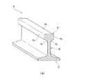
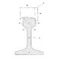
すなわち、図8に示す如く、鉄道レール(以下、単にレールと称する)Rは、頭部A、腹部B、底部Cの3つの部位から構成され、上記頭部Aは、上方を望む頭頂部Atと、左右の側部As,Asとを有し、さらに頭部Aと腹部Bとを繋ぐ左右の顎下部(上首部)Aj,Ajを有している。 That is, as shown in FIG. 8, a rail (hereinafter simply referred to as a rail) R is composed of three parts, a head A, an abdomen B, and a bottom C. And left and right side portions As and As, and further, left and right lower jaw portions (upper neck portions) Aj and Aj that connect the head A and the abdomen B.
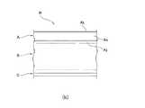
また、図9に示す如く、上記レールRの頭部Aにおける頭頂部Atには、鉄道車輌における車輪Wの踏面Wtが当接し、上記頭部Aにおける一方(軌間の内方側)の側部Asには、上記車輪WにおけるフランジWfが当接することとなる。
ここで、上述したレールRの頭部Aには、走行する鉄道車輌の荷重が作用することによって、内部に横裂等の損傷が発生する虞れがあり、鉄道車輌の安全な運行には、上記損傷の早期発見とともに、上記損傷に対する適切な処置が不可欠である。Further, as shown in FIG. 9, the tread surface Wt of the wheel W in the railway vehicle abuts on the top portion At of the head A of the rail R, and one side (inward side of the gauge) of the head A is side portion. The flange Wf of the wheel W comes into contact with As.
Here, on the head A of the rail R described above, there is a possibility that damage such as lateral cracks may occur inside due to the load of the traveling railway vehicle acting on the rail R. For safe operation of the railway vehicle, Along with the early detection of the damage, appropriate treatment for the damage is essential.
レールRの頭部Aに生じた損傷を発見する手段としては、従来より超音波探傷検査が採用されており、その一例として、図10に示す如くレールRの頭部Aの一方(図中左側)の顎下部Ajに発信用の探触子Peを接触させ、他方(図中右側)の顎下部Ajに受信用の探触子Prを接触させ、探触子Peから頭部Aの頭頂部Atに向けて超音波を発信し、探触子Prが受診したエコーを解析することによって、特に頭頂部At近傍に生じた損傷を発見するのに有効な、探傷方法および装置の提供が為されている(例えば、特許文献1および特許文献2参照)。
なお、上記超音波は、図10中、右側から入射し、左側で受信する構成の場合もある。Conventionally, ultrasonic flaw detection has been employed as a means for detecting damage occurring in the head A of the rail R. As one example, one of the heads A of the rail R (left side in the figure) is used as an example. ) With the transmitting probe Pe in contact with the lower chin Aj of the head and the receiving probe Pr with the lower chin Aj on the other (right side in the figure), and the top of the head A from the probe Pe. By providing ultrasonic waves toward At and analyzing the echoes received by the probe Pr, it is possible to provide a flaw detection method and apparatus that are particularly effective for finding damages occurring near the parietal region At. (For example, see
In addition, the said ultrasonic wave may enter from the right side in FIG. 10, and may be the structure received on the left side.
ところで、上述の如き超音波探傷検査を実施する際に、一対の探触子Pe,Prを接触させるレールRの顎下部Aj,Ajは、通常、メンテナンスの為されない部位であるため、表面に発生した錆や付着したオイル等によって著しく汚れている。
このように汚れている顎下部Aj,Ajに探触子Pe,Prを接触させた場合、グリセリン等の接触媒質を介在させた状態であっても、探触子PeからレールRの内部への超音波の入射、およびレールRの内部から探触子Prへの超音波の受信が阻害され、これによって超音波探傷検査の実施が困難となる不都合を招く。By the way, when performing the ultrasonic flaw inspection as described above, the lower jaw portions Aj and Aj of the rail R with which the pair of probes Pe and Pr are brought into contact with each other usually occur on the surface because they are not subjected to maintenance. It is extremely dirty due to rust and attached oil.
When the probes Pe and Pr are brought into contact with the dirty lower jaw portions Aj and Aj in this manner, the probe Pe can be moved into the rail R even when a contact medium such as glycerin is interposed. Incidence of ultrasonic waves and reception of ultrasonic waves from the inside of the rail R to the probe Pr are hindered, thereby causing inconvenience that it is difficult to perform ultrasonic flaw detection inspection.
そこで、超音波探傷検査を実施する場合には、検査に先んじてワイヤブラシや手持ちのディスクサンダ等を用い、レールRにおける顎下部Aj,Ajの表面(探傷面)から錆やオイル等の汚れを除去する清掃作業が必要となる。 Therefore, when conducting an ultrasonic flaw inspection, a wire brush or a hand-held disc sander is used prior to the inspection to remove dirt such as rust and oil from the surface of the lower jaw Aj, Aj (flaw detection surface) on the rail R. Cleaning work to remove is necessary.
しかし、敷設されたレールRは低い位置に在ることから、ワイヤブラシ等を使用しての清掃作業は、中腰等の無理な姿勢を作業員に強いることとなり、また顎下部Aj,Ajの表面は下方を向いているために、ワイヤブラシ等を適切に当てて清掃することも難しく、もって顎下部Aj,Ajに対する清掃作業を効率良く実施するには困難を伴っていた。 However, since the laid rail R is at a low position, cleaning work using a wire brush or the like forces the worker to take an unreasonable posture such as a middle waist and the surface of the lower jaws Aj and Aj. Since it faces downward, it is difficult to clean it by properly applying a wire brush or the like, and thus it is difficult to efficiently perform the cleaning work on the lower jaws Aj and Aj.
上述の如き実状に鑑みて、本願発明の目的は、作業員に無理な姿勢を強いることなく、探傷面であるレールの顎下部の表面を、容易かつ確実に研磨・清掃することのできる、レール顎下部清掃装置を提供することにある。 In view of the above situation, the object of the present invention is to provide a rail that can easily and reliably polish and clean the surface of the lower jaw of the rail, which is a flaw detection surface, without forcing an operator to take an unreasonable posture. It is to provide a lower jaw cleaning device.
上記目的を達成するべく、請求項1の発明に係るレール顎下部清掃装置は、走行ローラを回転自在に支承し該走行ローラにより鉄道レール上を走行移動し得る装置本体と、該装置本体に設けられ清掃ブラシを回転自在に支承するブラシ支持体と、該ブラシ支持体に設けられ清掃ブラシを回転駆動するブラシ駆動源とを有し、さらに装置本体に対して上下動自在に支承された走行ローラを装置本体に対して下方へ付勢することにより、清掃ブラシを鉄道レールに対して上方へ付勢する第1のバネ手段と、清掃ブラシを鉄道レールの幅方向に移動させるよう装置本体に揺動支持されたブラシ支持体を、清掃ブラシが鉄道レールに接近する方向へ付勢する第2の付勢手段とを備え、鉄道レールにセットした状態において、走行ローラを鉄道レールの頭頂部に圧接させるとともに、清掃ブラシを鉄道レールの顎下部に圧接させ、装置本体を走行移動させることによって、清掃ブラシにより顎下部を清掃するよう構成したことを特徴としている。 In order to achieve the above object, a rail lower jaw cleaning device according to the invention of
また、請求項2の発明に係るレール顎下部清掃装置は、請求項1の発明に係るレール顎下部清掃装置において、清掃ブラシは鉄道レールの長手方向に沿って延在する形態を呈し、前後方向に延びる回転軸およびブラシ材を備え、ブラシ支持体は上下方向に延在する支持アームを備え、該支持アームの下部に清掃ブラシの回転軸を支承し、ブラシ駆動源はブラシ支持体の上部に配設され、支持アームに沿って上下方向に延在する伝達軸を介して、清掃ブラシにおける回転軸を駆動することを特徴としている。 Further, the rail lower part cleaning device according to the invention of
請求項1の発明に係るレール顎下部清掃装置では、鉄道レールにセットした状態において、装置本体を走行移動させることにより、清掃ブラシによって顎下部を清掃するよう構成したので、レール顎下部清掃装置を走行移動させることによって、作業員に中腰等の無理な姿勢を強いることなく、楽な姿勢で鉄道レールの顎下部に対する研磨・清掃作業を実施することが可能となる。 In the rail lower part cleaning device according to the invention of
また、請求項1の発明に係るレール顎下部清掃装置では、第1の付勢手段と第2の付勢手段とによって清掃ブラシを付勢したことで、形状の相違する複数種類の鉄道レールに対しても、また鉄道レールの頭頂面が摩耗している状況においても、鉄道レールの顎下部に清掃ブラシが当接されることとなり、もって顎下部の表面を有効に研磨・清掃することが可能となる。 Moreover, in the rail chin lower part cleaning apparatus which concerns on invention of
請求項2の発明に係るレール顎下部清掃装置によれば、清掃ブラシが鉄道レールの長手方向に沿って延在する形態を呈し、ブラシ支持体の支持アームが上下方向に延在するとともに、ブラシ駆動源は支持アームに沿って上下方向に延在する伝達軸を介して清掃ブラシを回転させているので、鉄道レールに対してレール顎下部清掃装置を着脱する際、および鉄道レールにセットした状態において研磨・清掃作業を実施する際に、鉄道レールに並行して敷設されている脱線防止ガードや踏切等との干渉を防止することが可能となる。 According to the rail chin lower part cleaning device according to the invention of
以下、本願発明に係るレール顎下部清掃装置の具体的な構成を、実施例を示す図面を参照しつつ詳細に説明する。
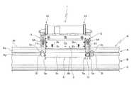
図1〜図4は、本願発明に係るレール顎下部清掃装置の一実施例を示しており、該レール顎下部清掃装置1(以下、清掃装置1と称する)は、装置本体としての本体フレーム2を具備し、この本体フレーム2には前後の走行ローラ3,3が、夫々回転自在に支承されている。Hereinafter, a specific configuration of the rail lower jaw cleaning device according to the present invention will be described in detail with reference to the drawings illustrating embodiments.
1 to 4 show an embodiment of a rail chin lower part cleaning apparatus according to the present invention. The rail chin lower part cleaning apparatus 1 (hereinafter referred to as the cleaning apparatus 1) is a
上記本体フレーム2は、平面視において矩形状を呈する枠構造体から成り、左右の側板2s,2sには、各走行ローラ3,3の支軸3a,3aを支承する長孔2o,2oが設けられ、これらの長孔2o,2oが上下に延在していることにより、走行ローラ3,3は本体フレーム2に対して上下動自在に支承されている。 The
また、本体フレーム2と走行ローラ3,3との間には、本体フレーム2に対して走行ローラ3を下方へ付勢する走行ローラ付勢バネ(第1の付勢手段)4が設けられ、詳しくは、本体フレーム2における側板2sのピン2pに係止された走行ローラ付勢バネ4が、走行ローラ3の支軸3aを下方に向けて付勢するように構成されている。 A travel roller biasing spring (first biasing means) 4 for biasing the
一方、上述した本体フレーム2の左右側部には、ブラシ支持体としての支持フレーム5,5が設けられており、これらの支持フレーム5,5には、各々清掃ブラシ6,6が回転自在に支承されている。 On the other hand,
ここで、上記清掃ブラシ6は、鉄道レール(以下、単にレールと称する)Rの長手方向に沿って延在する形態を呈しており、前後方向(レールRの長手方向)に延在する中心の回転軸6aと、この回転軸6aの周囲に設けられて穂先が螺旋を描くスクリュー状のブラシ材6bとを具備している。 Here, the
上記支持フレーム5は、レールRの長手方向に沿って延在する上部ビーム5bと、上下方向に延在する3つの支持アーム5a,5a,5aとを有し、これら支持アーム5aの下部には、上述した清掃ブラシ6の回転軸6aが回転自在に支承され、さらに清掃ブラシ6のブラシ材6bの外側方を覆うブラシカバー5cが設けられている。 The
また、本体フレーム2の左右に位置する支持フレーム5,5は、支持アーム5aの下部に支承した清掃ブラシ6を、レールRの幅方向(左右方向)に移動させる態様で、上記本体フレーム2に対して、前後一対の軸支ピン5A,5Aにより揺動支持されている。 The
さらに、上述した左右の支持フレーム5,5の間には、夫々の支持フレーム5,5に支承されている清掃ブラシ6,6を、レールRに接近させる方向へ付勢する支持フレーム付勢バネ(第2の付勢手段)7,7が設けられている。 Further, between the left and
詳しくは、左右の支持フレーム5,5における、夫々の上部ビーム5b,5bの間に、圧縮バネから構成された支持フレーム付勢バネ7,7を介装することで、各々の支持フレーム5,5に支承された清掃ブラシ6,6を、互いに接近する方向へ付勢するよう構成されている。 More specifically, support
また、支持フレーム5における各支持アーム5aの下端には、レールRに清掃装置1をセットする際、後述する如く機能するカム面5acが形成されており、さらに支持フレーム5における前方と後方の支持アーム5a,5aには、清掃装置1をレールRにセットした際、レールRの側部Asに当接する側方ガイドローラ5sと、レールRの下顎部Ajに当接する下方ガイドローラ5lとが、夫々、回転自在に支承されている。 In addition, a cam surface 5ac that functions as described later when the
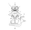
上記支持フレーム5における上部ビーム5bには、ブラシ駆動源としてのディスクサンダ10が設置されており、該ディスクサンダ10のスピンドル(回転軸)には、支持フレーム5の支持アーム5aに沿って上下方向に延在する伝達軸11が連結され、この伝達軸11と清掃ブラシ6の回転軸6aとの間には、ねじ歯車(ヘリカルギヤ)12が介装されており、もって清掃ブラシ6は、ディスクサンダ10から伝達軸11、ねじ歯車12を介して伝達される駆動力により回転されることとなる。 The
因みに、実施例における清掃装置1は、前後の全長が約400mm、全高が約300mm、左右の全幅が約200mmの外観を呈し、さらに前後方向における中心の垂直軸を対称軸として180°回転する毎に一致する、いわゆる二回回転対称を成す外観を呈している。 Incidentally, the
上述のように構成された実施例の清掃装置1が、図1〜図3に示す如くレールRに対してセットされた状態においては、図3に明示するように、本体フレーム2に支承された走行ローラ3が、レールRにおける頭部Aの頭頂部Atに載置されているとともに、左右の支持フレーム5,5に支承された清掃ブラシ6,6が、レールRにおける頭部Aの顎下部Ajに当接している。 The
ここで、上記走行ローラ3は、先に詳述した如く、走行ローラ付勢バネ(第1の付勢手段)4によって、本体フレーム2に対して下方へ付勢されているので、走行ローラ3がレールRの頭頂部Atに載置している状態においては、走行ローラ3に対して本体フレーム2が上方へ付勢され、本体フレーム2に設けられた左右の支持フレーム5,5が上動することで、支持フレーム5,5の支持アーム5aに支承されている下方ガイドローラ5l,5lが、レールRの顎下部Ajに当接することとなる。 Here, the traveling
また、左右の支持フレーム5,5は、先に詳述した如く、支持フレーム付勢バネ(第2の付勢手段)7によって、清掃ブラシ6がレールRに接近する方向へ付勢されているので、支持フレーム5,5の支持アームaに支承されている側方ガイドローラ5s,5sがレールRの側部Asに圧接することとなる。 The left and right support frames 5 and 5 are urged in a direction in which the
このように、下方ガイドローラ5l,5lがレールRの顎下部Ajに圧接し、かつ側方ガイドローラ5s,5sがレールRの側部Asに圧接することで、左右の支持フレーム5,5に支承されている清掃ブラシ6,6は、レールRの顎下部Ajに対する最適な相対位置に占位することとなる。 Thus, the lower guide rollers 5l and 5l are in pressure contact with the lower jaw portion Aj of the rail R, and the
したがって、清掃装置1をレールRにセットした状態では、レールRの頭頂部Atに走行ローラ3が圧接するとともに、レールRの顎下部Ajに対する最適な位置に清掃ブラシ6が位置することとなり、この状況において左右の清掃ブラシ6,6を駆動回転させつつ、作業員によって清掃装置1を走行移動させることによって、レールRにおける左右の顎下部Ajが連続して研磨・清掃されることとなる。 Therefore, in the state where the
上述した如く、実施例の清掃装置1においては、レールRにセットした状態で走行移動させることにより、清掃ブラシ6,6によって顎下部Aj,Ajを清掃するよう構成したので、上記清掃装置1を走行移動させることによって、作業員に中腰等の無理な姿勢を強いることなく、楽な姿勢でレールRの顎下部Ajに対する研磨・清掃作業を実施することが可能となる。
また、清掃装置1に引綱や長柄(図示せず)を取り付けることで、作業時における作業員の姿勢の自由度が格段に向上し、例えば通常に歩行するような楽な姿勢で清掃装置1を走行させ、レールRに対する研磨・清掃作業を実施することも可能である。As described above, in the
In addition, by attaching a towline or a long handle (not shown) to the
なお、清掃装置1によるレールRの研磨・清掃作業時、清掃ブラシ6によってレールRから除去された錆の粉塵等は、ブラシカバー5cに案内されてレールRの近傍に落下するので、周囲へ不用意に飛散することが未然に防止されることとなる。 During polishing and cleaning of the rail R by the
また、実施例の清掃装置1においては、上述した如く、走行ローラ付勢バネ(第1の付勢手段)4により、走行ローラ3が本体フレーム2に対して下方へ付勢されているので、レールRの頭部Aの頭頂面Atにおける摩耗量の如何んに関わらず、本体フレーム2に設けられた左右の支持フレーム5,5が上動し、清掃ブラシ6,6をレールRの顎下部Ajに対する最適な相対位置に占位させるため、清掃装置1を走行させることでレールRに対する研磨・清掃作業を実施できる。 In the
同じく、実施例の清掃装置1においては、走行ローラ付勢バネ(第1の付勢手段)4により、走行ローラ3が本体フレーム2に対して下方へ付勢されているので、図6に示したレール(60kgレール)Rと、図7に示したレール(50kgNレール)Rとのように、頭部Aにおける寸法が相違している場合であっても、本体フレーム2に設けられた左右の支持フレーム5,5が上動し、清掃ブラシ6,6をレールRの顎下部Ajに対する最適な相対位置に占位させるため、形状の相違する複数種類のレールRに対しても、何等の部品交換を必要とすることなく、清掃装置1を走行させることで研磨・清掃作業を実施できる。 Similarly, in the
また、図6に示したレール(60kgレール)Rと、図7に示したレール(50kgNレール)Rとでは、夫々の顎下部Ajにおける形状が互いに相違しているものの、清掃装置1における清掃ブラシ6のブラシ材6bは、通常、金属や樹脂の細線から成るため変形し得るので、異なる形状の顎下部Ajに対しても有効に当接することとなり、形状が互いに相違する異種類のレールRに対しても、何等の部品交換を必要とすることなく、顎下部Ajの研磨・清掃作業を実施できる。 Further, the rail (60 kg rail) R shown in FIG. 6 and the rail (50 kg N rail) R shown in FIG. 7 are different from each other in the lower jaw portion Aj, but the cleaning brush in the
一方、上述した如き実施例の清掃装置1をレールRにセットする場合には、先ず、図5(a)に示す如く、左右の支持フレーム5,5における支持アーム5a,5aの下端に形成されたカム面5ac,5acを、レールRの頭部Aに当接させた状態から、清掃装置1を矢印Dで示す如く押下することにより、上記カム面5ac,5acがレールRの頭部Aの側部と摺接することで、左右の支持フレーム5,5における支持アーム5a,5aが、支持フレーム付勢バネ7の付勢力に抗して、矢印O,Oで示す如く開くこととなり、さらに清掃装置1を押下することによって、上記カム面5ac,5acがレールRの頭部Aを乗り越えると、左右の支持フレーム5,5における支持アーム5a,5aが、支持フレーム付勢バネ7の付勢力によって閉じることにより、清掃装置1は図5(b)に示す如くレールRに対する所定の位置(図3参照)にセットされることとなる。 On the other hand, when the
ここで、実施例の清掃装置1によれば、清掃ブラシ6がレールRの長手方向に沿って延在する形態を呈し、支持フレーム5の支持アーム5aが上下方向に延在するとともに、清掃ブラシ6は支持アーム5aに沿って上下方向に延在する伝達軸11を介して駆動回転されるので、図5に示す如くレールRに並行して脱線防止ガードGが敷設されている現場や図示しない踏切においても、レールRに対して清掃装置1を着脱する際、および清掃装置1をレールRにセットして研磨・清掃作業を実施する際に、上記脱線防止ガードGとの干渉を未然に防止することができる。 Here, according to the
なお、上述した如き実施例の清掃装置1においては、本体フレーム2の左右両側に清掃ブラシ6,6を備えているために、レールRの頭部Aにおける左右の顎下部Aj,Ajを、1回の走行によって同時に研磨・清掃することができ、もってレールRに対する清掃作業の効率が極めて良好である。因みに、レールRにおける一方の顎下部Ajのみを清掃する場合においても、清掃装置1から一方の清掃ブラシ6を取外すことによって容易に対応することが可能である。 In the
また、実施例の清掃装置1においては、電動工具のディスクサンダ10をブラシ駆動源としたことで、特殊な電源装置を必要とすることなく、現場で使用する小型発電機からのAC100V電源で動作させることができ、もって超音波探傷検査の実施に関わるコストの低減に極めて効果的である。 Moreover, in the
さらに、実施例の清掃装置1によれば、清掃ブラシ6をレールRの長手方向に延在する形状としたことで、上記装置1の走行に伴って移動する清掃ブラシ6が、レールRにおける特定の点に対して連続して接触するため、レールRに対する研磨・清掃作業が確実かつ効果的に実施されることとなる。 Furthermore, according to the
1 レール顎下部清掃装置
2 本体フレーム(装置本体)
3 走行ローラ
4 走行ローラ付勢バネ(第1の付勢手段)
5 支持フレーム(ブラシ支持体)
5a 支持アーム
6 清掃ブラシ
6a 回転軸
6b ブラシ材
7 支持フレーム付勢バネ(第2の付勢手段)
10 ディスクサンダ(ブラシ駆動源)
11 伝達軸
12 ねじ歯車
R レール(鉄道レール)
A 頭部
At 頭頂部
As 側部
Aj 顎下部
B 腹部
C 底部
G 脱線防止ガード1 Rail lower
3 Traveling roller 4 Traveling roller biasing spring (first biasing means)
5 Support frame (Brush support)
10 Disc sander (brush drive source)
11
A head At head top As side Side Aj Lower jaw B Abdomen C Bottom G Derailment prevention guard
Claims (2)
Translated fromJapanese走行ローラを回転自在に支承し、前記走行ローラにより前記鉄道レール上を走行移動し得る装置本体と、
前記装置本体に設けられ、清掃ブラシを回転自在に支承するブラシ支持体と、
前記ブラシ支持体に設けられ、前記清掃ブラシを回転駆動するブラシ駆動源とを有し、
前記装置本体に対して上下動自在に支承された前記走行ローラを、前記装置本体に対して下方へ付勢することにより、前記清掃ブラシを前記鉄道レールに対して上方へ付勢する第1のバネ手段と、
前記清掃ブラシを前記鉄道レールの幅方向に移動させるよう前記装置本体に揺動支持された前記ブラシ支持体を、前記清掃ブラシが前記鉄道レールに接近する方向へ付勢する第2の付勢手段とを備え、
前記鉄道レールにセットした状態において、前記走行ローラを前記鉄道レールの頭頂部に圧接させるとともに、前記清掃ブラシを前記鉄道レールの顎下部に圧接させ、前記装置本体を走行移動させることによって、前記清掃ブラシにより前記顎下部を清掃するよう構成したことを特徴とするレール顎下部清掃装置。A rail lower jaw cleaning device for polishing and cleaning the surface of the lower jaw prior to ultrasonic flaw detection performed by bringing a probe into contact with the lower jaw of the head of a railroad rail,
An apparatus main body which rotatably supports a traveling roller and can travel on the railroad rail by the traveling roller;
A brush support provided in the apparatus main body and rotatably supporting the cleaning brush;
A brush drive source provided on the brush support and configured to rotate and drive the cleaning brush;
A first roller that biases the cleaning brush upward with respect to the railroad rail by biasing the traveling roller supported so as to be movable up and down with respect to the device main body downward. Spring means;
Second urging means for urging the brush support supported by the apparatus main body so as to move the cleaning brush in the width direction of the railway rail in a direction in which the cleaning brush approaches the railway rail. And
In the state set on the railroad rail, the cleaning roller is pressed against the top of the railroad rail, and the cleaning brush is pressed against the lower chin of the railroad rail to move the apparatus main body, thereby moving the cleaning body. A rail lower jaw cleaning device characterized by cleaning the lower jaw with a brush.
前記ブラシ支持体は、上下方向に延在する支持アームを備え、該支持アームの下部に前記清掃ブラシの前記回転軸を支承し、
前記ブラシ駆動源は、前記ブラシ支持体の上部に配設され、前記支持アームに沿って上下方向に延在する伝達軸を介して、前記清掃ブラシにおける前記回転軸を駆動する、
ことを特徴とする請求項1記載のレール顎下部清掃装置。The cleaning brush has a form extending along the longitudinal direction of the railroad rail, and includes a rotating shaft and a brush material extending in the front-rear direction,
The brush support includes a support arm extending in the vertical direction, and supports the rotating shaft of the cleaning brush at a lower portion of the support arm.
The brush drive source is disposed on an upper portion of the brush support and drives the rotating shaft of the cleaning brush through a transmission shaft extending in the vertical direction along the support arm.
The rail lower chin cleaning apparatus according to claim 1, wherein:
Priority Applications (1)
| Application Number | Priority Date | Filing Date | Title |
|---|---|---|---|
| JP2013136965AJP6141700B2 (en) | 2013-06-28 | 2013-06-28 | Rail lower jaw cleaning device |
Applications Claiming Priority (1)
| Application Number | Priority Date | Filing Date | Title |
|---|---|---|---|
| JP2013136965AJP6141700B2 (en) | 2013-06-28 | 2013-06-28 | Rail lower jaw cleaning device |
Publications (2)
| Publication Number | Publication Date |
|---|---|
| JP2015010949A JP2015010949A (en) | 2015-01-19 |
| JP6141700B2true JP6141700B2 (en) | 2017-06-07 |
Family
ID=52304231
Family Applications (1)
| Application Number | Title | Priority Date | Filing Date |
|---|---|---|---|
| JP2013136965AExpired - Fee RelatedJP6141700B2 (en) | 2013-06-28 | 2013-06-28 | Rail lower jaw cleaning device |
Country Status (1)
| Country | Link |
|---|---|
| JP (1) | JP6141700B2 (en) |
Families Citing this family (1)
| Publication number | Priority date | Publication date | Assignee | Title |
|---|---|---|---|---|
| KR102159466B1 (en)* | 2020-03-24 | 2020-09-24 | 김윤석 | Robot vacuum-cleaner of billiard table exclusive |
Family Cites Families (12)
| Publication number | Priority date | Publication date | Assignee | Title |
|---|---|---|---|---|
| JPS5249516A (en)* | 1975-10-14 | 1977-04-20 | Nippon Telegr & Teleph Corp <Ntt> | Automatic rail cleaning apparatus for monorail track |
| JPS58156702U (en)* | 1982-04-15 | 1983-10-19 | 株式会社下村電友舎製作所 | Grinding machine for rail welds |
| JPS6360310A (en)* | 1986-08-29 | 1988-03-16 | 芝浦メカトロニクス株式会社 | Track cleaning vehicle |
| SE461229B (en)* | 1987-05-11 | 1990-01-22 | Maehler & Soener | PROCEDURE AND DEVICE FOR CLEANING RAELS |
| JP2577240B2 (en)* | 1988-03-17 | 1997-01-29 | 株式会社芝浦製作所 | Rail oil removal cleaning equipment |
| JP2837628B2 (en)* | 1994-03-24 | 1998-12-16 | 操 新田 | Method for smoothing joint surface on rail and apparatus used in this method |
| ATE166035T1 (en)* | 1994-04-06 | 1998-05-15 | Speno International | ULTRASONIC MEASURING DEVICE FOR DEFECTS IN A RAILWAY RAIL |
| JPH10113720A (en)* | 1996-10-11 | 1998-05-06 | Nippon Steel Corp | Rail Ultrasonic Testing Pretreatment Descaling Method and Apparatus |
| JP3559823B2 (en)* | 1998-08-17 | 2004-09-02 | 三智合成 有限会社 | Rail blasting equipment |
| WO2006010196A1 (en)* | 2004-07-26 | 2006-02-02 | 5 Star Enterprises Pty Limited | An apparatus for removing debris from railway tracks |
| JP5121531B2 (en)* | 2008-03-28 | 2013-01-16 | 公益財団法人鉄道総合技術研究所 | Rail flaw detection method and apparatus |
| JP2013036770A (en)* | 2011-08-04 | 2013-02-21 | Railway Technical Research Institute | Method and apparatus for continuously detecting flaw of rail head part |
- 2013
- 2013-06-28JPJP2013136965Apatent/JP6141700B2/ennot_activeExpired - Fee Related
Also Published As
| Publication number | Publication date |
|---|---|
| JP2015010949A (en) | 2015-01-19 |
Similar Documents
| Publication | Publication Date | Title |
|---|---|---|
| CN104755674B (en) | Method and apparatus for grinding rails of railroad tracks | |
| JP2013542351A5 (en) | ||
| EP2761089B1 (en) | Tangential grinding machine | |
| KR101373803B1 (en) | apparatus for clearing of rail | |
| CN106414850A (en) | Tangential grinding machine for railway profiles | |
| JP6141700B2 (en) | Rail lower jaw cleaning device | |
| CN209335320U (en) | A kind of track arrangement for grinding | |
| KR101194791B1 (en) | Turnout rail grinding machine | |
| JP2013520590A (en) | Driveable device for forming the top of the rail track | |
| WO2011059395A1 (en) | Method and machine for treatment of railway joints | |
| KR101524981B1 (en) | Railroad repair vehicles | |
| AU725345B2 (en) | A device for the continuous and fine reprofiling in situ of the surface of the head of at least one rail of a railway track | |
| KR101591260B1 (en) | Apparatus of skin pass mill | |
| JPS624481B2 (en) | ||
| CN204019314U (en) | Derusting device before steel plate weldering | |
| KR101089436B1 (en) | Roll debris removal device | |
| CN108176638B (en) | Surface treatment platform for gray cast iron parts | |
| JP6764700B2 (en) | Deburring device for trolley wire | |
| CN201776283U (en) | Roller face cleaning device of planishing mill | |
| CN104014944A (en) | Automatic steel plate welding machine | |
| CN215881139U (en) | Brake block is polished and is used piece cleaning device | |
| CN110076672B (en) | Automatic grinding device of robot | |
| CN203125271U (en) | Planar steel formwork welding seam polishing machine | |
| JP2004106132A (en) | Polishing equipment for wheels | |
| JP2010264476A (en) | Welding post-treatment device |
Legal Events
| Date | Code | Title | Description |
|---|---|---|---|
| A621 | Written request for application examination | Free format text:JAPANESE INTERMEDIATE CODE: A621 Effective date:20160628 | |
| A977 | Report on retrieval | Free format text:JAPANESE INTERMEDIATE CODE: A971007 Effective date:20170324 | |
| TRDD | Decision of grant or rejection written | ||
| A01 | Written decision to grant a patent or to grant a registration (utility model) | Free format text:JAPANESE INTERMEDIATE CODE: A01 Effective date:20170404 | |
| A61 | First payment of annual fees (during grant procedure) | Free format text:JAPANESE INTERMEDIATE CODE: A61 Effective date:20170508 | |
| R150 | Certificate of patent or registration of utility model | Ref document number:6141700 Country of ref document:JP Free format text:JAPANESE INTERMEDIATE CODE: R150 | |
| LAPS | Cancellation because of no payment of annual fees |