JP6141480B2 - System and method for monitoring shochu scale - Google Patents
System and method for monitoring shochu scaleDownload PDFInfo
- Publication number
- JP6141480B2 JP6141480B2JP2016056456AJP2016056456AJP6141480B2JP 6141480 B2JP6141480 B2JP 6141480B2JP 2016056456 AJP2016056456 AJP 2016056456AJP 2016056456 AJP2016056456 AJP 2016056456AJP 6141480 B2JP6141480 B2JP 6141480B2
- Authority
- JP
- Japan
- Prior art keywords
- microwave antenna
- microwave
- tissue
- ablation zone
- reflectivity
- Prior art date
- Legal status (The legal status is an assumption and is not a legal conclusion. Google has not performed a legal analysis and makes no representation as to the accuracy of the status listed.)
- Active
Links
- 238000012544monitoring processMethods0.000titleclaimsdescription11
- 235000020083shōchūNutrition0.000titleclaimsdescription3
- 238000000034methodMethods0.000titledescription25
- 238000002679ablationMethods0.000claimsdescription85
- 238000002310reflectometryMethods0.000claimsdescription44
- 239000012809cooling fluidSubstances0.000claimsdescription10
- 238000004891communicationMethods0.000claimsdescription9
- 230000005540biological transmissionEffects0.000claimsdescription4
- 230000000630rising effectEffects0.000claimsdescription4
- 239000012530fluidSubstances0.000claimsdescription3
- 210000001519tissueAnatomy0.000description59
- 230000000875corresponding effectEffects0.000description13
- 238000005259measurementMethods0.000description12
- 239000004020conductorSubstances0.000description7
- 238000011282treatmentMethods0.000description7
- 238000004364calculation methodMethods0.000description5
- 206010028980NeoplasmDiseases0.000description4
- 230000008859changeEffects0.000description4
- -1but not limited toSubstances0.000description3
- 238000001816coolingMethods0.000description3
- 230000006378damageEffects0.000description3
- 238000010586diagramMethods0.000description3
- 230000005670electromagnetic radiationEffects0.000description3
- 210000004185liverAnatomy0.000description3
- 229910052709silverInorganic materials0.000description3
- 239000004332silverSubstances0.000description3
- RYGMFSIKBFXOCR-UHFFFAOYSA-NCopperChemical compound[Cu]RYGMFSIKBFXOCR-UHFFFAOYSA-N0.000description2
- 201000011510cancerDiseases0.000description2
- 229910052802copperInorganic materials0.000description2
- 239000010949copperSubstances0.000description2
- 230000002596correlated effectEffects0.000description2
- 239000003989dielectric materialSubstances0.000description2
- PCHJSUWPFVWCPO-UHFFFAOYSA-NgoldChemical compound[Au]PCHJSUWPFVWCPO-UHFFFAOYSA-N0.000description2
- 229910052737goldInorganic materials0.000description2
- 239000010931goldSubstances0.000description2
- 210000002216heartAnatomy0.000description2
- 238000010438heat treatmentMethods0.000description2
- 210000003734kidneyAnatomy0.000description2
- 210000004072lungAnatomy0.000description2
- 239000000463materialSubstances0.000description2
- 238000012986modificationMethods0.000description2
- 230000004048modificationEffects0.000description2
- 238000012545processingMethods0.000description2
- 230000005855radiationEffects0.000description2
- 239000007787solidSubstances0.000description2
- 206010020843HyperthermiaDiseases0.000description1
- BQCADISMDOOEFD-UHFFFAOYSA-NSilverChemical compound[Ag]BQCADISMDOOEFD-UHFFFAOYSA-N0.000description1
- 238000013459approachMethods0.000description1
- 239000000919ceramicSubstances0.000description1
- 230000001276controlling effectEffects0.000description1
- 238000001514detection methodMethods0.000description1
- 238000002405diagnostic procedureMethods0.000description1
- 201000010099diseaseDiseases0.000description1
- 208000037265diseases, disorders, signs and symptomsDiseases0.000description1
- 230000036031hyperthermiaEffects0.000description1
- 230000002427irreversible effectEffects0.000description1
- 208000007106menorrhagiaDiseases0.000description1
- 229910052751metalInorganic materials0.000description1
- 239000002184metalSubstances0.000description1
- 150000002739metalsChemical class0.000description1
- 230000017074necrotic cell deathEffects0.000description1
- 239000012811non-conductive materialSubstances0.000description1
- 210000000056organAnatomy0.000description1
- 230000037368penetrate the skinEffects0.000description1
- 230000035699permeabilityEffects0.000description1
- 210000002307prostateAnatomy0.000description1
- 230000002285radioactive effectEffects0.000description1
- 238000001959radiotherapyMethods0.000description1
- 230000008672reprogrammingEffects0.000description1
- 229910001220stainless steelInorganic materials0.000description1
- 239000010935stainless steelSubstances0.000description1
- 238000002560therapeutic procedureMethods0.000description1
- 230000019432tissue deathEffects0.000description1
Images


Classifications
- A—HUMAN NECESSITIES
- A61—MEDICAL OR VETERINARY SCIENCE; HYGIENE
- A61B—DIAGNOSIS; SURGERY; IDENTIFICATION
- A61B18/00—Surgical instruments, devices or methods for transferring non-mechanical forms of energy to or from the body
- A61B18/18—Surgical instruments, devices or methods for transferring non-mechanical forms of energy to or from the body by applying electromagnetic radiation, e.g. microwaves
- A61B18/1815—Surgical instruments, devices or methods for transferring non-mechanical forms of energy to or from the body by applying electromagnetic radiation, e.g. microwaves using microwaves
- A—HUMAN NECESSITIES
- A61—MEDICAL OR VETERINARY SCIENCE; HYGIENE
- A61B—DIAGNOSIS; SURGERY; IDENTIFICATION
- A61B18/00—Surgical instruments, devices or methods for transferring non-mechanical forms of energy to or from the body
- A61B18/18—Surgical instruments, devices or methods for transferring non-mechanical forms of energy to or from the body by applying electromagnetic radiation, e.g. microwaves
- H—ELECTRICITY
- H04—ELECTRIC COMMUNICATION TECHNIQUE
- H04W—WIRELESS COMMUNICATION NETWORKS
- H04W64/00—Locating users or terminals or network equipment for network management purposes, e.g. mobility management
- H04W64/003—Locating users or terminals or network equipment for network management purposes, e.g. mobility management locating network equipment
- A—HUMAN NECESSITIES
- A61—MEDICAL OR VETERINARY SCIENCE; HYGIENE
- A61B—DIAGNOSIS; SURGERY; IDENTIFICATION
- A61B18/00—Surgical instruments, devices or methods for transferring non-mechanical forms of energy to or from the body
- A61B2018/00571—Surgical instruments, devices or methods for transferring non-mechanical forms of energy to or from the body for achieving a particular surgical effect
- A61B2018/00577—Ablation
- A—HUMAN NECESSITIES
- A61—MEDICAL OR VETERINARY SCIENCE; HYGIENE
- A61B—DIAGNOSIS; SURGERY; IDENTIFICATION
- A61B18/00—Surgical instruments, devices or methods for transferring non-mechanical forms of energy to or from the body
- A61B2018/00636—Sensing and controlling the application of energy
- A61B2018/00642—Sensing and controlling the application of energy with feedback, i.e. closed loop control
- A—HUMAN NECESSITIES
- A61—MEDICAL OR VETERINARY SCIENCE; HYGIENE
- A61B—DIAGNOSIS; SURGERY; IDENTIFICATION
- A61B18/00—Surgical instruments, devices or methods for transferring non-mechanical forms of energy to or from the body
- A61B2018/00636—Sensing and controlling the application of energy
- A61B2018/00666—Sensing and controlling the application of energy using a threshold value
- A—HUMAN NECESSITIES
- A61—MEDICAL OR VETERINARY SCIENCE; HYGIENE
- A61B—DIAGNOSIS; SURGERY; IDENTIFICATION
- A61B18/00—Surgical instruments, devices or methods for transferring non-mechanical forms of energy to or from the body
- A61B2018/00636—Sensing and controlling the application of energy
- A61B2018/00684—Sensing and controlling the application of energy using lookup tables
- A—HUMAN NECESSITIES
- A61—MEDICAL OR VETERINARY SCIENCE; HYGIENE
- A61B—DIAGNOSIS; SURGERY; IDENTIFICATION
- A61B18/00—Surgical instruments, devices or methods for transferring non-mechanical forms of energy to or from the body
- A61B2018/00636—Sensing and controlling the application of energy
- A61B2018/00696—Controlled or regulated parameters
- A61B2018/00702—Power or energy
- A—HUMAN NECESSITIES
- A61—MEDICAL OR VETERINARY SCIENCE; HYGIENE
- A61B—DIAGNOSIS; SURGERY; IDENTIFICATION
- A61B18/00—Surgical instruments, devices or methods for transferring non-mechanical forms of energy to or from the body
- A61B2018/00636—Sensing and controlling the application of energy
- A61B2018/00773—Sensed parameters
- A61B2018/00779—Power or energy
- A61B2018/00785—Reflected power
Landscapes
- Health & Medical Sciences (AREA)
- Life Sciences & Earth Sciences (AREA)
- Surgery (AREA)
- Engineering & Computer Science (AREA)
- Electromagnetism (AREA)
- Animal Behavior & Ethology (AREA)
- Nuclear Medicine, Radiotherapy & Molecular Imaging (AREA)
- Otolaryngology (AREA)
- Veterinary Medicine (AREA)
- Public Health (AREA)
- Biomedical Technology (AREA)
- Heart & Thoracic Surgery (AREA)
- Medical Informatics (AREA)
- Molecular Biology (AREA)
- Physics & Mathematics (AREA)
- General Health & Medical Sciences (AREA)
- Computer Networks & Wireless Communication (AREA)
- Signal Processing (AREA)
- Surgical Instruments (AREA)
Description
Translated fromJapanese本開示は、組織の焼灼処置で用いることができるシステムおよび方法に関する。より具体的には、本開示は、実時間における組織の焼灼処置の最中に焼灼規模を監視するためのシステムおよび方法に関する。 The present disclosure relates to systems and methods that can be used in tissue ablation procedures. More specifically, the present disclosure relates to systems and methods for monitoring ablation scale during real-time tissue ablation procedures.
癌等の疾患の治療において、特定の種類の癌細胞が昇温(健康細胞に通常は有害な温度よりわずかに低い温度)で変性することが分かっている。一般に温熱治療として知られるこうした種類の治療は、罹患細胞を41℃超過の温度に加熱するために電磁放射を典型的に利用し、一方で、不可逆的な細胞破壊が起こることのない、より低い温度に隣接する健康細胞を維持する。組織を加熱するために電磁放射を利用する処置としては、組織の焼灼を挙げることができる。 In the treatment of diseases such as cancer, it has been found that certain types of cancer cells denature at elevated temperatures (a temperature slightly lower than that normally harmful to healthy cells). This type of treatment, commonly known as hyperthermia, typically utilizes electromagnetic radiation to heat diseased cells to temperatures in excess of 41 ° C., while lower without irreversible cell destruction. Maintain healthy cells adjacent to temperature. Treatments that utilize electromagnetic radiation to heat the tissue include tissue ablation.
マイクロ波焼灼処置、例えば、月経過多症に対して実施されるもの等の処置は、標的組織を焼灼し、その組織を変性または死滅させるために典型的に行われる。電磁放射療法を利用する多くの処置および多種の機器が、当該技術分野で知られている。このようなマイクロ波療法は、前立腺、心臓、および肝臓等の組織および器官の治療で典型的に用いられる。 Microwave ablation procedures, such as those performed on menorrhagia, are typically performed to cauterize the target tissue and denature or kill the tissue. Many treatments and a variety of devices that utilize electromagnetic radiation therapy are known in the art. Such microwave therapy is typically used in the treatment of tissues and organs such as the prostate, heart, and liver.
1つの非侵襲的処置は一般的に、マイクロ波エネルギーの使用を通じて、皮膚の下にある組織(例えば、腫瘍)の治療を伴う。マイクロ波エネルギーは、皮膚に非侵襲的に浸透し、下にある組織に達することができる。しかしながら、この非侵襲的処置は、健常組織の不要な加熱をもたらし得る。従って、マイクロ波エネルギーの非侵襲的使用は、多大な制御が要求される。 One non-invasive procedure generally involves treatment of tissue (eg, a tumor) under the skin through the use of microwave energy. Microwave energy can penetrate the skin non-invasively and reach the underlying tissue. However, this non-invasive procedure can result in unnecessary heating of healthy tissue. Thus, non-invasive use of microwave energy requires a great deal of control.
現在、焼灼域の規模を監視するための何種かのシステムおよび方法がある。場合によっては、1種以上のセンサ(または他の適切な機器)が、マイクロ波焼灼機器と操作可能に関連付けられる。例えば、単極アンテナ構成を含むマイクロ波焼灼機器において、伸長したマイクロ波導体が、そのマイクロ波導体の端で露出したセンサと操作的に連通し得る。この種類のセンサは時々、誘電性の軸鞘により包囲される。 Currently, there are several systems and methods for monitoring the size of the ablation zone. In some cases, one or more sensors (or other suitable devices) are operably associated with the microwave ablation device. For example, in a microwave ablation device that includes a single pole antenna configuration, an elongated microwave conductor can be in operative communication with a sensor exposed at the end of the microwave conductor. This type of sensor is sometimes surrounded by a dielectric shaft sheath.
典型的には、前述の種類の1つまたは複数のセンサは、マイクロ波焼灼機器が作動しない、すなわち、放射していない場合に機能する(例えば、電力源の出力を制御するための制御装置に帰還を提供する)ように構成される。つまり、前述のセンサは実時間で機能しない。典型的には、センサが、電力源を制御するように構成された制御装置および/または他の1つまたは複数の機器に帰還(例えば、組織温度)を提供している時に、電力源は電力が切れる(またはパルスが止まる)。 Typically, one or more sensors of the type described above function when the microwave ablation device is not activated, i.e., is not radiating (e.g., to a controller for controlling the power source output). Provide feedback). That is, the aforementioned sensor does not function in real time. Typically, when a sensor is providing feedback (eg, tissue temperature) to a controller and / or one or more other devices configured to control the power source, the power source Is cut off (or the pulse stops).
本開示は、実時間における焼灼規模を監視するためのシステムを提供する。当該システムは、1つ以上の制御アルゴリズムを実行するためのマイクロプロセッサを含む電力源を含む。マイクロ波アンテナは、焼灼域を形成するために、電力源から組織へマイクロ波エネルギーを運搬するように構成される。焼灼域の制御モジュールは、電力源と関連する記憶装置と操作的に連通する。当該記憶装置は、時間とともに変化する制御曲線に関連するデータを含み、かつ、マイクロ波アンテナと関連する1つ以上の電気的パラメータを表す、1つ以上のデータ参照表を含む。制御曲線に沿った点はその電気的パラメータの値に対応し、1つまたは複数の電気的パラメータの所定の閾値が焼灼域の半径に対応して測定される場合、焼灼域の制御モジュールが信号を引き起こす。 The present disclosure provides a system for monitoring the scale of ablation in real time. The system includes a power source that includes a microprocessor for executing one or more control algorithms. The microwave antenna is configured to carry microwave energy from the power source to the tissue to form an ablation zone. The ablation zone control module is in operative communication with a storage device associated with the power source. The storage device includes data associated with a control curve that varies over time and includes one or more data look-up tables that represent one or more electrical parameters associated with the microwave antenna. A point along the control curve corresponds to the value of that electrical parameter, and if a predetermined threshold of one or more electrical parameters is measured corresponding to the radius of the ablation zone, the ablation zone control module can signal cause.
本開示は、焼灼処置を実施するために構成された、電力源に接続するように適合されたマイクロ波アンテナも提供する。マイクロ波アンテナは、電力源から組織へマイクロ波エネルギーを運搬し、焼灼域を形成するように構成された放射部を含む。焼灼域の制御モジュールは、電力源と関連する記憶装置と操作的に連通する。当該記憶装置は、時間とともに変化する制御曲線に関連するデータを含み、かつ、マイクロ波アンテナと関連する1つ以上の電気的パラメータを表す、1つ以上のデータ参照表を含む。制御曲線に沿った点は1つまたは複数の電気的パラメータの値に対応し、少なくとも1つの電気的パラメータの所定の閾値が焼灼域の半径に対応して測定される場合、焼灼域の制御モジュールは信号を引き起こす。 The present disclosure also provides a microwave antenna adapted to connect to a power source configured to perform an ablation procedure. The microwave antenna includes a radiating portion configured to carry microwave energy from a power source to tissue to form an ablation zone. The ablation zone control module is in operative communication with a storage device associated with the power source. The storage device includes data associated with a control curve that varies over time and includes one or more data look-up tables that represent one or more electrical parameters associated with the microwave antenna. A point along the control curve corresponds to the value of one or more electrical parameters, and if a predetermined threshold of at least one electrical parameter is measured corresponding to the radius of the ablation zone, the ablation zone control module Causes a signal.
本開示は、焼灼を受ける組織の温度を監視するための方法も提供する。当該方法は、組織の焼灼域を形成するために、電力源からマイクロ波アンテナにマイクロ波エネルギーを伝達する最初のステップを含む。当該方法の一ステップとしては、組織の焼灼域が形成する際に、マイクロ波アンテナと関連する反射力を測定することが挙げられる。当該方法の一ステップとしては、マイクロ波アンテナで所定の反射力に到達する場合、制御信号を電力源に伝えることが挙げられる。電力源からそのマイクロ波アンテナへのマイクロ波エネルギーの量を調節することは、当該方法の別のステップである。 The present disclosure also provides a method for monitoring the temperature of tissue undergoing ablation. The method includes an initial step of transmitting microwave energy from a power source to a microwave antenna to form a tissue ablation zone. One step in the method includes measuring the reflectivity associated with the microwave antenna as the ablation zone of the tissue forms. One step in the method is to transmit a control signal to a power source when a predetermined reflectivity is reached with a microwave antenna. Adjusting the amount of microwave energy from the power source to its microwave antenna is another step of the method.
本開示の上述および他の態様、特徴、および利点は、以下の添付図面と併用すれば、以下の発明を実施するための形態に鑑みてより明白になるだろう。 The above and other aspects, features and advantages of the present disclosure will become more apparent in view of the following detailed description when taken in conjunction with the accompanying drawings.
ここで開示されるシステムおよび方法の実施形態は、同様の参照番号が同様または同一の要素を特定する作図を参照して詳細に記載される。本明細書で用いられるように、かつ従来のように、用語「遠位(の)」は使用者から最も遠い部分を指し、用語「近位(の)」は使用者に最も近い部分を指す。加えて、「上方」、「下方」、「前方」、「後方」などのような用語は、図の位置付けまたは構成部の方向を指し、描写の便宜のためにのみ用いられる。 Embodiments of the systems and methods disclosed herein are described in detail with reference to drawings wherein like reference numbers identify like or identical elements. As used herein and as is conventional, the term “distal” refers to the portion furthest from the user and the term “proximal” refers to the portion closest to the user. . In addition, terms such as “upper”, “lower”, “front”, “rear”, etc. refer to the positioning of the figure or the direction of the components and are used only for convenience of depiction.
ここで図1を参照すると、焼灼規模を監視するためのシステムが10と指定されている。システム10は、電気外科的電力源、例えば、1つ以上の制御装置300、および、場合によっては、流体供給ポンプ40を含むか操作的に連通する、RFおよび/またはマイクロ波(MW)の発生器200に接続するように適合されるマイクロ波アンテナ100を含む。簡潔には、マイクロ波アンテナ100は、細長い心棒112と、細長い心棒112の内部に操作可能に配置された放射性または伝導性の部分または先端114とを有する導入器116、冷却鞘121を有する冷却組立体120、取手118、冷却流体供給装置122と冷却流体回帰装置124、および電気外科的エネルギーの接続器126を含む。接続器126は、マイクロ波アンテナ100を電気外科的電力源200、例えば、無線周波数エネルギーおよび/またはマイクロ波エネルギーの発生器または源に接続し、かつ、電気外科的エネルギーをマイクロ波アンテナ100の遠位部分に供給するように構成される。伝導性の先端114および細長い心棒112は、マイクロ波アンテナ100の近位端から延在し、かつ、心棒112の内部にかつ伝導性または放射性の先端114(例えば、図3Aを参照されたい)に隣接して動作可能に配置された放射部138に操作的に連結される内部伝導体の先端を含む内部同軸ケーブル126a(例えば、図3Aを参照されたい)を通じて、接続器126と電気的に連通する。当該技術分野では一般的であるように、内部同軸ケーブル126aは、誘電性材料と、内部伝導体の先端および誘電性材料のそれぞれを囲む外部伝導体とを含む。マイクロ波アンテナ100の近位端に配置された接続ハブ(図示せず)は、接続器126を内部同軸ケーブル126aに、かつ、冷却流体供給装置122と冷却流体回帰装置124を冷却組立部120に操作可能に連結する。伝導性の先端114を経由する(または、場合によっては、伝導性の先端114を有しない)放射部138は、(双極モードまたは単極モードのうち何れかの)無線周波数エネルギー、あるいは、(約500MHz〜約10GHzの周波数を有する)マイクロ波エネルギーを標的組織部位に運搬するように構成される。銅、金、銀、または、同様の伝導性値を有する他の伝導性金属を含むが、これらに限定されない適切な伝導性材料から、細長い心棒112および伝導性の先端114を形成することができる。代替的には、細長い心棒112および/または伝導性の先端114をステンレス鋼から構成することができ、あるいは、他の材料、例えば、金または銀等の他の伝導性材料で鍍金して、特定の特性を改善し、例えば、伝導性を改善し、エネルギー損失を減少させることなどができる。一実施形態では、伝導性の先端は、細長い心棒112から展開可能であり得る。1つの具体的な実施形態では、マイクロ波アンテナ100が、細長い心棒112と、非伝導性である先端114とを有する導入器116を含み得る。この場合、例えば、セラミック、プラスチックなどのような非伝導性材料から、先端114を作成することができる。 Referring now to FIG. 1, a system for monitoring the scale of shochu is designated as 10.
図2を参照すると、発生器200の略ブロック図が例解されている。発生器200は、1つ以上のモジュール(例えば、焼灼域の制御モジュール332(AZCM332)、電力供給装置237、およびマイクロ波出力段238)を有する制御装置300を含む。この場合、発生器200はマイクロ波エネルギーの運搬に関して記載される。電力供給装置237は、DC力をマイクロ波エネルギーに変換し、そのマイクロ波エネルギーをマイクロ波アンテナ100の放射部138に運搬するマイクロ波出力段238にDC力を提供する。制御装置300は、AZCM332により提供された感知値を処理し、マイクロプロセッサ335を通じて発生器200および/または供給ポンプ40に送られる制御信号を測定するためのアナログ回路および/または論理回路を含み得る。制御装置300(または、当該制御装置と操作可能に関連する構成部)は、マイクロ波アンテナがエネルギーを放射している時に、マイクロ波アンテナ100と関連する反射力Prを示す、1つ以上の測定信号を受け入れる。Referring to FIG. 2, a schematic block diagram of the
制御装置300の1つ以上のモジュール、例えば、AZCM332は、その測定信号を分析し、閾値の反射力Pr、例えば、Pr1が満たされているかどうかを判定する。その閾値の反射力Pr1が満たされている場合、その時、AZCM332、マイクロプロセッサ335、および/または制御装置は、マイクロ波出力段238および/または電力供給装置237を適宜に調節するように、発生器200に指示する。加えて、制御装置300は、マイクロ波アンテナ100および/または周囲の組織に対する冷却流体の量を調節するように、供給ポンプにも信号を送り得る。制御装置200は、揮発性型記憶装置(例えば、RAM)および/または不揮発性型記憶装置(例えば、フラッシュ媒体、ディスク媒体など)であり得る記憶装置336を有するマイクロプロセッサ335を含む。例解されている実施形態では、マイクロプロセッサ335は、開いたおよび/または閉じた制御ループ配列の何れかに従い、マイクロプロセッサ335が発生器300の出力を制御することを可能にする、電力供給装置237および/またはマイクロ波出力段238と操作的に連通する。マイクロプロセッサ335は、AZCM332により受信されるデータを処理するためのソフトウェア命令、および、制御信号を発生器300および/または供給ポンプ40に適宜に出力するためのソフトウェア命令を実行することができる。制御装置300により実行可能であるソフトウェア命令は、記憶装置336内に記憶される。One or more modules of the
発生器200により生成された信号(またはパルス)に関連する、1つ以上の電気的特性(例えば、電圧、電流、電力、インピーダンスなど)を監視および測定することができる。より具体的には、発生器200により生成された信号の前方部分および反射部分と関連する電気的特性が監視および測定される。例えば、1つの具体的な実施形態では、組織を焼灼するための信号の前方電力および反射電力、PfおよびPrはそれぞれ、AZCM332、制御装置300、マイクロプロセッサ337、あるいは、発生器200および/または制御装置300と関連する他の適切なモジュールにより測定される。One or more electrical characteristics (eg, voltage, current, power, impedance, etc.) associated with the signal (or pulse) generated by
組織の焼灼規模を予測するための1つ以上の制御アルゴリズムは、制御装置300により実行される。より具体的には、特定のマイクロ波アンテナ、例えば、マイクロ波アンテナ100と関連する反射力Prを、半径「r」を有する焼灼域「A」と相関させる概念を用い、組織の死滅または壊死を示すことができる。より具体的には、マイクロ波アンテナ100と関連する反射力Prは、温度増加により引き起こされた組織の複合的な浸透性の変化が原因で、焼灼周期にわたって変化する(例えば、図4Aおよび4Bを参照されたい)。図4Aで例解されている制御曲線により、時間の関数としての反射力Prの関係が表される。同様に、図4Bで例解されている制御曲線により、焼灼規模の関数としての反射力Prの関係が表される。図4Aおよび4Bで表される制御曲線は、マイクロ波アンテナ100、制御装置300、および/または発生器200を用いて実施される焼灼処置の最中に取り込まれた、モデル関数f(t)および反射力Prの既知の測定値に基づく。本開示に従い、図4Aおよび4Bで描写される制御曲線(および/または、それに数学的に関連する方程式)を利用し、特定の閾値の反射力Pr(例えば、反射力Pr1−ss)がtssを超えない特定の時間範囲内(例えば、t1〜tss)にある時、すなわち、マイクロ波アンテナ100および焼灼された組織が定常状態条件にある時間を計算および/または検証することができ、例えば、図4Aまたは図4Bを参照されたい。マイクロ波アンテナ100および焼灼された組織が定常状態条件にある時の意義は、以下により詳細に記載される。One or more control algorithms for predicting the ablation scale of the tissue are executed by the
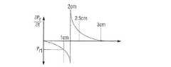
ここで図4Aおよび4Bを参照すると、最初に、マイクロ波アンテナ100が加熱されていない組織内に挿入される場合、マイクロ波アンテナ100と組織との間にインピーダンスの不整合が存在する。このインピーダンスの不整合は、放射部118および/または伝導性の先端114のインピーダンスと整合しない、内部ケーブル126aと関連する50Ωのインピーダンスが原因である。インピーダンスの不整合は、焼灼処置の開始時に非零反射力Priを結果的にもたらす(例えば、図4Aおよび4Bを参照されたい)。焼灼処置の過程において、マイクロ波アンテナ100と組織との間の最適なインピーダンスの整合に到達するまで(2cmに等しい半径「r」を有する焼灼規模にある図4Bと組み合わせて、時間t2に等しい時間における図4Aを参照されたい)、「近接場」内の組織は温まり、(非線形速度における)反射力Prの減少を結果的にもたらす(例えば、図4Aを参照されたい)。つまり、「近接場」内のマイクロ波アンテナ100および組織の合計のインピーダンスZtは50Ωにほぼ等しい。「近接場」内のマイクロ波アンテナ100および組織は、少しの間この最適なインピーダンスのままである。時間t2の後の時間において、近接場内のマイクロ波アンテナ100および組織は、(非線形速度における)その最適なインピーダンスの整合から発散する。最終的に、マイクロ波アンテナ100が最大の到達可能な温度に組織を加熱していた場合、対応する半径「r」(例えば、rss)を有する焼灼域「A」が形成される(例えば、図4Aおよび4Bと組み合わせて図3Aを参照されたい)。この最大温度において、焼灼された組織と関連する誘電定数および伝導度は、マイクロ波アンテナ100と関連する定常状態の反射力Prss(以後、単にPrssと呼ばれる)に対応する定常状態条件(この定常状態条件は、時間tssに起こる)に到達する。つまり、焼灼された組織がマイクロ波アンテナ100の「近接場」内にあるので、焼灼された組織が本質的にマイクロ波アンテナ100の一部となる。従って、焼灼された組織と関連する誘電定数および伝導度が定常状態条件に到達する時、マイクロ波アンテナ100での反射力Prも定常状態条件、例えば、図4AのPrssに到達する。Referring now to FIGS. 4A and 4B, when the
上述したように、前述の制御アルゴリズムは、図4Aおよび4Bで例解されるモデル曲線を表す1つ以上のモデル関数f(t)を含む。モデル関数f(t)、図4Aおよび4Bで描写されるモデル曲線、および/または反射力Prの既知の測定値は、焼灼域の実時間監視を実現することができるように、反射力Prに関連する情報を得るために利用される。より具体的には、制御曲線のうち何れか(例えば、図4Aで例解される曲線)に沿った点における接線の勾配の測定結果は、その点における曲線の微分係数(dPr/dt)に等しい。1つまたは複数の曲線に沿った特定の点における微分係数の計算結果は、反射力Prに関する情報を提供する。より具体的には、時間に対する反射力Prの変化率、より具体的には、反射力Prの変化率のベクトル量(すなわち、方向(正方向または負方向)およびその変化率の大きさ)が、図4A〜4Cで描写される1つまたは複数の制御曲線から計算される。時間に対する反射力Prに関連するこの変化率を利用して、例えば、反射力Prの上昇と下降とを区別することができる。より具体的には、図4Aおよび4Bで描写される制御曲線に沿った点は、反射力Pr、例えば、反射力Pr1およびPr3の値に対応し、これは、対応する時間t、例えば、時間t1およびt3で半径「r」、例えば、半径r1およびr3を有する焼灼域「A」に対応する。反射力の値、例えば、Pr1は、焼灼域の1つより多い半径、例えば、r1およびr3に対応することに留意されたい。As described above, the control algorithm described above includes one or more model functions f (t) that represent the model curves illustrated in FIGS. 4A and 4B. Model function f (t), known measurements of model curve, and / or reflected power Pr is depicted in FIGS. 4A and 4B, so it is possible to realize a real-time monitoring of the ablation zone, reflected power P Used to obtain information related tor . More specifically, the measurement result of the tangential slope at a point along any of the control curves (eg, the curve illustrated in FIG. 4A) is the derivative of the curve (dPr / dt) at that point. be equivalent to. The calculation result of the derivative at a particular point along one or more curves provides information about the reflectivityPr . More specifically, the rate of change of reflected power Pr with respect to time, and more specifically, a vector quantity of the rate of change of reflected power Pr (i.e., direction (positive or negative direction) and magnitude of the rate of change ) Is calculated from one or more control curves depicted in FIGS. Using this rate of change associated with reflected power Pr with respect to time, for example, it is possible to distinguish between rising and falling of the reflected power Pr. More specifically, the points along the control curve depicted in FIGS. 4A and 4B correspond to the values of the reflectivity Pr , eg, reflectivity Pr1 and Pr3 , which corresponds to the corresponding time t, For example, corresponding to ablation zone “A” having radii “r” at times t1 and t3 , eg, radii r1 and r3 . Note that the value of reflectivity, eg, Pr1 , corresponds to more than one radius of the ablation zone, eg, r1 and r3 .
より具体的には、図4Aおよび4Bで描写される反射力Prの代表的な制御曲線は、焼灼処置の開始時において、初期値、例えば、Piを有する反射力Prを例解する。反射力Prがほぼ0に等しくなるまで、すなわち、「近接場」内のマイクロ波アンテナ100および組織の合計のインピーダンスが50Ωにほぼ等しくなる時、反射力Prは減少する。「近接場」内のマイクロ波アンテナ100および組織の合計のインピーダンスが50Ωに等しくない場合、時間t2の後の時間に、反射力Prは増加する。従って、制御曲線に沿った反射力Prの測定値は、対応する半径「r」を有する1つ以上の焼灼域「A」を示す、反射力Prの1つ以上の数値を提供する。例えば、時間t1における反射力Prの測定値、例えば、Pr1は、1cmにほぼ等しい半径r1を有する焼灼域「A」に対応する(図4Aおよび4Bをまとめて参照されたい)。同様に、時間t3における反射力Prの測定値、例えば、Pr1は、2.2cmにほぼ等しい半径r3を有する焼灼域「A」に対応し、図4Aおよび4Bをまとめて参照されたい。More specifically, representative control curve of reflected power Pr that is depicted in Figure 4A and 4B, at the beginning of the ablation procedure, an initial value, for example, illustrating an reflected power Pr with Pi . Until it equals the reflected power Pr is approximately 0, ie, the total impedance of
本開示に従い、当該制御曲線に沿った選択点(例えば、半径r1およびr3に対応する点、および/または、時間t1およびt3に対応する点)で取られた微分係数の標本は、制御曲線に対する反射力Prの正確な位置(例えば、制御曲線の上昇部分または下降部分)に関連する情報を提供する。In accordance with the present disclosure, a derivative sample taken at selected points along the control curve (eg, points corresponding to radii r1 and r3 and / or points corresponding to times t1 and t3 ) is provides precise location of the reflected power Pr with respect to the control curve (e.g., raised portions or falling portion of the control curve) information related to.
より具体的に、かつ例えば、図4Cで最良に見られるように、反射力Prの勾配が下がっているので、反射力PrがPr1にほぼ等しい時間t1における制御曲線に沿った点で取られた微分係数は負である。この場合、反射力Pr1を負の値を有すると考えてよく、かつ、負の値を割り当てられ、制御装置300および/または発生器200と関連する1つ以上のモジュール、例えば、AZCM332に、反射力Pr1のこの値が半径r1を有する焼灼域「A」を示しかつ対応することを示す。同様に、図4Cで最良に見られるように、反射力Prの勾配が増加しているので、反射力PrがPr1にほぼ等しい時間t3における制御曲線に沿った点で取られた微分係数の標本は正である。この場合、反射力Pr1を正の値を有すると考えてよく、かつ、正の値を割り当てられ、制御装置300および/または発生器200と関連する1つ以上のモジュール、例えば、AZCM332に、反射力Pr1のこの値が半径r3を有する焼灼域「A」を示しかつ対応することを示す。More particularly, and for example, as best seen in Figure 4C, since the down slope of the reflected power Pr, that the reflected power Pr is along the control curve at approximately equal time t1 to Pr1 The derivative taken at is negative. In this case, the reflectivity Pr1 may be considered to have a negative value and is assigned a negative value and is associated with one or more modules associated with the
制御曲線上の点において取られた微分係数の計算結果を利用する制御アルゴリズムを実行することにより、焼灼域「A」の正確な規模を決定することが容易になる。つまり、制御装置300および発生器200と関連する1つ以上のモジュール、例えば、AZCM332は、どの焼灼域の半径「r」、例えば、半径r1またはr2が、反射力Pr、例えば、測定された反射力Pr1に対応するかを識別することができる。さらに、多数の焼灼域「A」が互いに隣接して配置される場合、焼灼域「A」の近接場における加熱されていない組織の組織インピーダンスは、反射力Prの測定値をもたらし得る。より具体的には、近接場における加熱されていない組織の組織インピーダンスは、わずかにより高くてもより低くてもよく(特定の隣接する焼灼域「A」に依存する)、これは、同様に、予想される以上に、反射力Prを焼灼処置の開始時により高くまたはより低くし得る。従って、初期の反射力PiがPr4にほぼ等しい場合、制御曲線上の点で取られた微分係数の計算結果は、マイクロ波アンテナ100が加熱または焼灼された組織に隣接して配置されることを示す。つまり、Pr4という正の初期値は、反射力Prが増加しており、それ故、定常状態条件が近づいていることを示し、すなわち、微分係数の計算結果は、測定された反射力Prが制御曲線の上昇部分内にあり、かつ、反射力Prが0、すなわち、マイクロ波アンテナ100および近接場に隣接する組織に関連する合計のインピーダンスが50Ωにほぼ等しい制御曲線上の点に近づくことはないことを示す。By executing a control algorithm that uses the calculation result of the differential coefficient taken at a point on the control curve, it becomes easy to determine the exact scale of the ablation zone “A”. That is, one or more modules associated with the
例えば、球形(図3A)、半球形、楕円形(焼灼域が「A−2」と指定される図3B)などのような任意の適切な構成(例えば、幅「w」および長さ「l」)を有する焼灼域「A」を創出するように、本開示のマイクロ波アンテナ100を構成することができる(例えば、図3を参照されたい)。1つの具体的な実施形態では、マイクロ波アンテナ100が、球形(図3A)である焼灼域「A」を創出するように構成される。上述の通り、マイクロ波アンテナ100が「近接場」内にある組織を最大温度に加熱した場合、焼灼された組織と関連する誘電定数および伝導度は、マイクロ波アンテナ100と関連する定常状態の反射力Prssに対応する定常状態に到達する。焼灼された組織(すなわち、誘電定数および伝導度が定常状態条件にある焼灼された組織)を伴う、マイクロ波アンテナ100と関連するPrssを相関させることにより、焼灼域「A」の特定の規模(例えば、半径rss)および形状(例えば、球形)が示される。従って、マイクロ波アンテナ100と関連するPrssの測定値は、半径r、例えば、rssを有する焼灼域「A」に対応する。本開示の制御アルゴリズムは、特定の半径の特定のマイクロ波アンテナと関連する既知の定常状態の反射力を用い、焼灼域を予測する。つまり、特定のマイクロ波アンテナ、例えば、マイクロ波アンテナ100と関連する反射力Pr、例えば、Prss、および、対応する半径、例えば、rssは、1つ以上の参照表「D」内に編集され、記憶装置、例えば、記憶装置336内に記憶され、マイクロプロセッサ335および/またはAZCM332により呼び出し可能である。従って、特定のマイクロ波アンテナ、例えば、マイクロ波アンテナ100の測定された反射力がPrssに到達する時、制御装置300と関連する1つ以上のモジュール、例えば、AZCM332は、マイクロ波アンテナ100に対する出力を適宜に調節するように制御装置200に命令する。この事象の組み合わせは、rssにほぼ等しい半径を有する焼灼域「A」を提供することになる。For example, any suitable configuration (eg, width “w” and length “l”, such as spherical (FIG. 3A), hemispherical, elliptical (FIG. 3B where the ablation zone is designated “A-2”), etc. The
一実施形態では、与えられたマイクロ波アンテナ、例えば、マイクロ波アンテナ100に関しては、tssより前の時間、例えば、時間t1〜t4で反射力測定を開始することができる。この場合、マイクロ波アンテナ100と関連する反射力、例えば、Pr1〜Pr4を、焼灼域「A」の中心から測定される場合、半径r1〜r4(半径rと集合的に呼ばれる)を有する複数の同心焼灼域により画定される焼灼域「A」と相関させることができる。より具体的には、反射力Pr1〜Pr4および対応する半径「r」を、Prssおよびrssに関して上記のような方法で互いに相関させることができる(例えば、図4Aおよび4Bと組み合わせて図3Aを参照されたい)。この場合、特定の反射力、例えば、P3が満たされる場合、制御装置300と関連する1つ以上のモジュール、例えば、AZCM332は、マイクロ波アンテナ100に対する出力を適宜に調節するように制御装置200に命令する。In one embodiment, for a given microwave antenna, eg,
マイクロ波アンテナ100に関連する反射力Prは、与えられたマイクロ波アンテナにより変化し得るということに留意されたい。与えられたマイクロ波アンテナに対する特定の反射力Prに寄与し得る要因としては、マイクロ波アンテナと関連する寸法(例えば、長さ、幅など)、銅、銀などのような、マイクロ波アンテナ(またはそれと関連する部分、例えば、放射部)を作製するために用いられる材料の種類、および、放射部の構成(双極、単極など)、および/または、マイクロ波アンテナと関連する伝導性の先端(例えば、鋭い、鈍い、曲がったなど)が挙げられるが、これらに限定されない。与えられたマイクロ波アンテナに対する特定の反射力Prに寄与し得る他の要因としては、例えば、マイクロ波アンテナの種類(例えば、肺、腎臓、肝臓などを治療する際の使用のために構成されたマイクロ波アンテナ)、治療される組織の種類(例えば、肺、腎臓、肝臓、心臓など)、腫瘍の規模などを挙げることができる。Note that the reflectivity Pr associated with the
AZCM332はマイクロプロセッサ335から分離したモジュールであってよく、あるいは、AZCM332はマイクロプロセッサ335を含んでよい。一実施形態では、マイクロ波アンテナ100上にAZCM332を動作可能に配置することができる。AZCM332は、1つ以上の制御モジュールおよび/または1つ以上のインピーダンスセンサ(図示せず)から情報を受信し、制御装置300および/またはマイクロプロセッサ335にその情報を提供する制御回路を含み得る。この場合、AZCM332、マイクロプロセッサ335、および/または制御装置300は、参照表「D」を呼び出し、特定の焼灼域、(例えば、半径rssを有する特定の焼灼域)に対応する、マイクロ波組立体100と関連する特定の反射力(例えば、Prss)が満たされていることを確認し、その後、マイクロ波アンテナに運搬されるマイクロ波エネルギーの量を調節するように発生器200に指示することができる。1つの具体的な実施形態では、マイクロ波アンテナ100と関連する記憶保存機器(図示せず)内に参照表「D」を保存することができる。より具体的には、参照表「D」を、マイクロ波アンテナ100の取手118および/または接続器126と操作的に関連する記憶保存機器内に保存することができ、マイクロプロセッサ335および/または記憶装置336内にダウンロードし、読み取り、保存し、その後、上記方法で呼び出して利用することができる。これは、特定のマイクロ波アンテナのために発生器200および/または制御装置300を再プログラムすることをなくすだろう。マイクロ波アンテナ100に関連する情報を含むように、記憶保存機器を構成することもできる。例えば、マイクロ波アンテナの種類、マイクロ波アンテナが治療するように構成される組織の種類、所望される焼灼域の種類などのような情報を、マイクロ波アンテナと関連する保存機器内に保存することができる。この場合、焼灼域「A」を創出するように構成されるマイクロ波アンテナ100のそれとは異なる焼灼域、例えば、焼灼域「A−2」を創出するように構成されたマイクロ波アンテナを伴う使用のために、システム10の発生器200および/または制御装置300を適合させることができる。The
図1〜4で例解されている実施形態では、発生器は流体供給ポンプ40に操作可能に連結されて示される。供給ポンプ40は、同様に、供給槽44に操作可能に連結される。実施形態では、マイクロプロセッサ335は、1つ以上の適切な種類のインターフェース、例えば、発生器200上に操作的に配置されたポート240を通じて供給ポンプ40と操作的に連通し、これにより、開いたおよび/または閉じた制御ループ配列の何れかに従い、マイクロプロセッサ335が供給ポンプ40からマイクロ波アンテナ100への冷却流体の出力を制御することが可能になる。制御装置300は、供給槽44からマイクロ波アンテナ100まで冷却流体の出力を制御するように供給ポンプ40に信号を送ることができる。このようにして、冷却流体42は自動的に、マイクロ波アンテナ100に循環され、供給ポンプ40に還流される。特定の実施形態では、臨床医は供給ポンプ40を手動で制御し、マイクロ波アンテナ100から周囲組織の中および/または付近へ冷却流体42を放出することができる。 In the embodiment illustrated in FIGS. 1-4, the generator is shown operably connected to the
システム10の操作がここで記載される。次の記載では、接続器126および/またはケーブル126aと関連する損失は無視できるものであり、それ故、焼灼処置の最中にその焼灼域に隣接するマイクロ波アンテナ100の反射力を計算および/または決定する際に必要とされないことが想定される。最初に、マイクロ波アンテナ100は発生器200に接続される。1つの具体的な実施形態では、発生器200および/または制御装置300と関連する1つ以上のモジュール、例えば、AZCM332は、アンテナ100と関連する保存機器からのデータ、例えば、マイクロ波アンテナの種類、治療されるべき組織の種類などを読み取り、および/またはダウンロードする。その後、マイクロ波アンテナ100を組織に隣接して配置することができる(図3A)。その後、組織を焼灼することができるように、発生器200を作動させ、マイクロ波アンテナ100の放射部138にマイクロ波エネルギーを供給することができる。組織の焼灼の最中に、マイクロ波アンテナ100において所定の反射力、例えば、Prssに到達する時、AZCM332はマイクロ波エネルギーを適宜に調節するように発生器200に指示する。前述の事象の順序では、AZCM332は実時間で機能し、適切な割合の均一な焼灼域(例えば、半径rssを有する焼灼域「A」)が、隣接する組織に対して最小の損傷を伴い、あるいは全く損傷を伴わずに形成されるように、焼灼域に対するマイクロ波エネルギーの量を制御する。The operation of
図5を参照すると、焼灼を受ける組織の温度を監視するための方法400が例解されている。ステップ402では、発生器200からのマイクロ波エネルギーが、組織の焼灼部位に隣接するマイクロ波アンテナ100に伝達される。ステップ404では、マイクロ波アンテナと関連する反射力Prが監視される。ステップ406では、所定の反射力Prにマイクロ波アンテナ100で到達する時、検出信号が発生器200に伝えられる。ステップ408では、発生器200からマイクロ波アンテナ100へのマイクロ波エネルギーの量を調節することができる。Referring to FIG. 5, a
前述の内容から、かつ、様々な作図を参照すると、当業者は、本開示の範囲から逸脱することなく、本開示に対して特定の修正を行うこともできることを十分理解するだろう。例えば、1つ以上の方向性結合器(図示せず)を、発生器200、制御装置300、および/またはAZCM332と操作的に関連付け、標本化出力信号(またはパルス)の前方電力、反射電力、および/または負荷電力の部分をAZCM332に向けるように構成することができる。より具体的には、方向性結合器は、発生器200により生成された前方信号および反射信号(またはパルス)の標本を提供する。1つ以上の適切な方程式を使用する従来のアルゴリズムにより測定された前方信号および反射信号から、生成された出力信号の電力、大きさ、および位相を取得または計算することができる。 From the foregoing, and with reference to various drawings, one of ordinary skill in the art will appreciate that certain modifications can be made to the present disclosure without departing from the scope of the present disclosure. For example, one or more directional couplers (not shown) are operatively associated with the
出力パルスのエネルギーの値またはパラメータ(例えば、電力、電圧、電流、インピーダンス、大きさ、または位相)は、発生器200の出力において有効であることに留意されたい。つまり、上で示唆したように、接続器126および/または内部ケーブル126aは、伝達線損失を含む場合がある。従って、マイクロ波アンテナ100に運搬され、および/または、反射して発生器200に戻るエネルギーの値またはパラメータのより正確な解釈および/または測定を得るために、接続器126および/または内部ケーブル126aと関連する実際の伝達線損失を知る必要があるだろう。従って、一実施形態では、接続器126および/または内部ケーブル126aの損失情報を決定し、その後、記憶装置336内に記憶され、例えば、較正モジュール(600)、または後で使用するための他の適切なモジュール(例えば、AZCM332)等の1つ以上のモジュールにより呼び出すことができる。任意の適切な機器および/または方法により、接続器126および/または内部ケーブル126aの損失情報を決定することができる。例えば、ネットワーク分析器602を通じて、接続器126および/または内部ケーブル126aの損失情報を決定することができる。1つの具体的な実施形態では、ネットワーク分析器602は発生器200の一体部分(例えば、較正モジュール600の一部)であり得、あるいは代替的に、ネットワーク分析器602は発生器200と操作的に連通する別個の手持ち式機器であり得る。ネットワーク分析器602を用い、接続器126および/または内部ケーブル126aの診断試験を実施することができる。ネットワーク分析器602は、利用可能な技術分野で知られているほとんどの従来のネットワーク分析器と同様の様式で機能することができる。つまり、ネットワーク分析器602は、接続器126および/または内部ケーブル126aと関連する特性、より具体的には、例えば、接続器126および/または内部ケーブル126aの特徴的なインピーダンスZo等の、出力信号の反射および/または伝達に影響を及ぼす、接続器126および/または内部ケーブル126aと関連するそうした特性を決定することができる。Note that the energy value or parameter (eg, power, voltage, current, impedance, magnitude, or phase) of the output pulse is valid at the output of the
接続器126および/または内部ケーブル126aと関連する既知の線損失情報を、記憶装置336内に記憶し、制御装置300および/または発生器200と関連する1つ以上のモジュール、例えば、AZCM332により焼灼処置の最中に呼び出し、その後、反射力Prの所定の閾値、例えば、Pr1−ssが満たされているかどうかを判定する際に用いることができる。より具体的には、接続器126および/または内部ケーブル126aと関連する特徴的なインピーダンスを使用し、より正確または包括的な反射力Prの測定値を決定することができる。例えば、以下の方程式を用いて、より正確または包括的な反射力Prの測定値を決定することができる:
本開示のいくつかの実施形態が図面で示され、および/または本明細書で検討されているものの、本開示は当該技術が許容するほど範囲が広範であり、かつ本明細書が同様に解釈されることを目的とするので、本開示を当該実施形態に限定することを目的としない。それ故、上の記載を制限としてではなく、単に具体的な実施形態の例示として解釈されたい。当業者は、本明細書に添付されている特許請求の範囲および趣旨の範囲内にある他の修正を構想するだろう。 Although some embodiments of the present disclosure are shown in the drawings and / or discussed herein, the present disclosure is as broad as the art allows, and the present description is similarly construed Therefore, the present disclosure is not intended to be limited to the embodiment. Therefore, the above description should not be construed as limiting, but merely as exemplifications of specific embodiments. Those skilled in the art will envision other modifications within the scope and spirit of the claims appended hereto.
Claims (14)
Translated fromJapaneseマイクロ波エネルギーを生成するように構成された電力源と、
前記電力源に連結され、かつ少なくとも1つの制御アルゴリズムを実行するように構成されたマイクロプロセッサと、
時間とともに変化するマイクロ波エネルギーの反射力の制御曲線に関連する1つ以上の電気的パラメータのデータを有する少なくとも1つのデータ参照表を含む記憶装置と、
焼灼域を形成するために、前記電力源から組織に前記マイクロ波エネルギーを運搬するように構成されたマイクロ波アンテナと、
前記記憶装置と操作的に連通する焼灼域の制御モジュールであって、前記焼灼域の制御モジュールは、前記マイクロ波アンテナと関連する制御曲線を特定するように構成され、前記アルゴリズムは、前記マイクロ波アンテナと関連する焼灼域を形成するために、前記マイクロ波アンテナにより運搬されたマイクロ波エネルギーを調節するように、前記制御曲線を利用するように構成される、焼灼域の制御モジュールと、
を備える、システム。A system for monitoring the scale of shochu, the system comprising:
A power source configured to generate microwave energy;
A microprocessor coupled to the power source and configured to execute at least one control algorithm;
A storage device including at least one datalook-up table having data ofone or more electrical parameters associated witha control curveof reflectivity of microwave energy that varies over time;
A microwave antenna configured to convey the microwave energy from the power source to tissue to form an ablation zone;
An ablation zone control module in operative communication with the storage device, wherein the ablation zone control module is configured to identify a control curve associated with the microwave antenna, and the algorithm includes the microwave An ablation zone control module configured toutilize the control curve to adjust the microwave energy carried by the microwave antenna to form an ablation zone associated with the antenna;
A system comprising:
をさらに備える、請求項5に記載のシステム。A network analyzer configured to determine a line loss associated with one of the microwave antenna connector and an internal cable;
The system of claim 5, further comprising:
をさらに備える、請求項1に記載のシステム。At least one fluid pump configured to supply a cooling fluid to the microwave antenna to cool one of the microwave antenna and tissue adjacent to the ablation zone;
The system of claim 1, further comprising:
Applications Claiming Priority (2)
| Application Number | Priority Date | Filing Date | Title |
|---|---|---|---|
| US12/607,268 | 2009-10-28 | ||
| US12/607,268US8382750B2 (en) | 2009-10-28 | 2009-10-28 | System and method for monitoring ablation size |
Related Parent Applications (1)
| Application Number | Title | Priority Date | Filing Date |
|---|---|---|---|
| JP2014258573ADivisionJP5908058B2 (en) | 2009-10-28 | 2014-12-22 | System and method for monitoring shochu scale |
Related Child Applications (1)
| Application Number | Title | Priority Date | Filing Date |
|---|---|---|---|
| JP2017091759ADivisionJP6370959B2 (en) | 2009-10-28 | 2017-05-02 | System and method for monitoring shochu scale |
Publications (2)
| Publication Number | Publication Date |
|---|---|
| JP2016135290A JP2016135290A (en) | 2016-07-28 |
| JP6141480B2true JP6141480B2 (en) | 2017-06-07 |
Family
ID=43602850
Family Applications (5)
| Application Number | Title | Priority Date | Filing Date |
|---|---|---|---|
| JP2010241881AActiveJP5705501B2 (en) | 2009-10-28 | 2010-10-28 | System and method for monitoring shochu scale |
| JP2014258573AActiveJP5908058B2 (en) | 2009-10-28 | 2014-12-22 | System and method for monitoring shochu scale |
| JP2016056456AActiveJP6141480B2 (en) | 2009-10-28 | 2016-03-22 | System and method for monitoring shochu scale |
| JP2017091759AExpired - Fee RelatedJP6370959B2 (en) | 2009-10-28 | 2017-05-02 | System and method for monitoring shochu scale |
| JP2018131425APendingJP2018158166A (en) | 2009-10-28 | 2018-07-11 | System and method for monitoring shochu scale |
Family Applications Before (2)
| Application Number | Title | Priority Date | Filing Date |
|---|---|---|---|
| JP2010241881AActiveJP5705501B2 (en) | 2009-10-28 | 2010-10-28 | System and method for monitoring shochu scale |
| JP2014258573AActiveJP5908058B2 (en) | 2009-10-28 | 2014-12-22 | System and method for monitoring shochu scale |
Family Applications After (2)
| Application Number | Title | Priority Date | Filing Date |
|---|---|---|---|
| JP2017091759AExpired - Fee RelatedJP6370959B2 (en) | 2009-10-28 | 2017-05-02 | System and method for monitoring shochu scale |
| JP2018131425APendingJP2018158166A (en) | 2009-10-28 | 2018-07-11 | System and method for monitoring shochu scale |
Country Status (3)
| Country | Link |
|---|---|
| US (4) | US8382750B2 (en) |
| EP (1) | EP2316369B1 (en) |
| JP (5) | JP5705501B2 (en) |
Cited By (1)
| Publication number | Priority date | Publication date | Assignee | Title |
|---|---|---|---|---|
| JP2018158166A (en)* | 2009-10-28 | 2018-10-11 | コビディエン エルピー | System and method for monitoring shochu scale |
Families Citing this family (48)
| Publication number | Priority date | Publication date | Assignee | Title |
|---|---|---|---|---|
| US7553309B2 (en) | 2004-10-08 | 2009-06-30 | Covidien Ag | Electrosurgical system employing multiple electrodes and method thereof |
| US8403924B2 (en) | 2008-09-03 | 2013-03-26 | Vivant Medical, Inc. | Shielding for an isolation apparatus used in a microwave generator |
| US9277969B2 (en)* | 2009-04-01 | 2016-03-08 | Covidien Lp | Microwave ablation system with user-controlled ablation size and method of use |
| WO2014143014A1 (en) | 2013-03-15 | 2014-09-18 | Triagenics, Llc | Therapeutic tooth bud ablation |
| CA2761652C (en) | 2009-05-11 | 2019-10-01 | Leigh E. Colby | Therapeutic tooth bud ablation |
| US10022202B2 (en)* | 2013-03-15 | 2018-07-17 | Triagenics, Llc | Therapeutic tooth bud ablation |
| US8323275B2 (en) | 2009-06-19 | 2012-12-04 | Vivant Medical, Inc. | Laparoscopic port with microwave rectifier |
| US8069553B2 (en) | 2009-09-09 | 2011-12-06 | Vivant Medical, Inc. | Method for constructing a dipole antenna |
| US9113925B2 (en)* | 2009-09-09 | 2015-08-25 | Covidien Lp | System and method for performing an ablation procedure |
| US9095359B2 (en) | 2009-09-18 | 2015-08-04 | Covidien Lp | Tissue ablation system with energy distribution |
| US8568398B2 (en) | 2009-09-29 | 2013-10-29 | Covidien Lp | Flow rate monitor for fluid cooled microwave ablation probe |
| US8568401B2 (en) | 2009-10-27 | 2013-10-29 | Covidien Lp | System for monitoring ablation size |
| US8430871B2 (en) | 2009-10-28 | 2013-04-30 | Covidien Lp | System and method for monitoring ablation size |
| US8394092B2 (en)* | 2009-11-17 | 2013-03-12 | Vivant Medical, Inc. | Electromagnetic energy delivery devices including an energy applicator array and electrosurgical systems including same |
| US8764744B2 (en)* | 2010-01-25 | 2014-07-01 | Covidien Lp | System for monitoring ablation size |
| US8491579B2 (en) | 2010-02-05 | 2013-07-23 | Covidien Lp | Electrosurgical devices with choke shorted to biological tissue |
| US8968288B2 (en) | 2010-02-19 | 2015-03-03 | Covidien Lp | Ablation devices with dual operating frequencies, systems including same, and methods of adjusting ablation volume using same |
| US8617153B2 (en) | 2010-02-26 | 2013-12-31 | Covidien Lp | Tunable microwave ablation probe |
| US8728067B2 (en) | 2010-03-08 | 2014-05-20 | Covidien Lp | Microwave antenna probe having a deployable ground plane |
| US8409188B2 (en) | 2010-03-26 | 2013-04-02 | Covidien Lp | Ablation devices with adjustable radiating section lengths, electrosurgical systems including same, and methods of adjusting ablation fields using same |
| US10039601B2 (en) | 2010-03-26 | 2018-08-07 | Covidien Lp | Ablation devices with adjustable radiating section lengths, electrosurgical systems including same, and methods of adjusting ablation fields using same |
| US9192436B2 (en) | 2010-05-25 | 2015-11-24 | Covidien Lp | Flow rate verification monitor for fluid-cooled microwave ablation probe |
| US8652127B2 (en) | 2010-05-26 | 2014-02-18 | Covidien Lp | System and method for chemically cooling an ablation antenna |
| US9241762B2 (en) | 2010-06-03 | 2016-01-26 | Covidien Lp | Specific absorption rate measurement and energy-delivery device characterization using image analysis |
| US8672933B2 (en) | 2010-06-30 | 2014-03-18 | Covidien Lp | Microwave antenna having a reactively-loaded loop configuration |
| US10588684B2 (en) | 2010-07-19 | 2020-03-17 | Covidien Lp | Hydraulic conductivity monitoring to initiate tissue division |
| GB201021032D0 (en)* | 2010-12-10 | 2011-01-26 | Creo Medical Ltd | Electrosurgical apparatus |
| US9055957B2 (en) | 2010-12-23 | 2015-06-16 | Covidien Lp | Microwave field-detecting needle assemblies, methods of manufacturing same, methods of adjusting an ablation field radiating into tissue using same, and systems including same |
| US9770294B2 (en) | 2011-01-05 | 2017-09-26 | Covidien Lp | Energy-delivery devices with flexible fluid-cooled shaft, inflow/outflow junctions suitable for use with same, and systems including same |
| US9028476B2 (en) | 2011-02-03 | 2015-05-12 | Covidien Lp | Dual antenna microwave resection and ablation device, system and method of use |
| US8992413B2 (en) | 2011-05-31 | 2015-03-31 | Covidien Lp | Modified wet tip antenna design |
| US9014789B2 (en) | 2011-09-22 | 2015-04-21 | The George Washington University | Systems and methods for visualizing ablated tissue |
| AU2012312066C1 (en) | 2011-09-22 | 2016-06-16 | 460Medical, Inc. | Systems and methods for visualizing ablated tissue |
| WO2013149245A1 (en) | 2012-03-31 | 2013-10-03 | Microcube, Llc | Returned power for microwave applications |
| WO2013184319A1 (en)* | 2012-06-04 | 2013-12-12 | Boston Scientific Scimed, Inc. | Systems and methods for treating tissue of a passageway within a body |
| CN103656865B (en)* | 2012-09-25 | 2016-12-21 | 郭运斌 | A kind of microwave energy transporter utilizing phased array antenna and method |
| JP6737705B2 (en) | 2013-11-14 | 2020-08-12 | ザ・ジョージ・ワシントン・ユニバーシティThe George Washingtonuniversity | Method of operating system for determining depth of injury site and system for generating images of heart tissue |
| JP2017500550A (en) | 2013-11-20 | 2017-01-05 | ザ・ジョージ・ワシントン・ユニバーシティThe George Washingtonuniversity | System and method for hyperspectral analysis of cardiac tissue |
| KR102499045B1 (en) | 2014-11-03 | 2023-02-10 | 더 조지 워싱턴 유니버시티 | Systems and methods for lesion assessment |
| EP3215001A4 (en) | 2014-11-03 | 2018-04-04 | Luxcath, LLC | Systems and methods for assessment of contact quality |
| AU2015374244B2 (en) | 2014-12-31 | 2019-11-21 | Covidien Lp | System and method for treating COPD and emphysema |
| US11039884B2 (en)* | 2015-06-12 | 2021-06-22 | The University Of Sydney | Microwave ablation device |
| US10779904B2 (en) | 2015-07-19 | 2020-09-22 | 460Medical, Inc. | Systems and methods for lesion formation and assessment |
| CN108882963B (en)* | 2016-03-22 | 2023-01-03 | 微立方有限责任公司 | Methods and apparatus for energy delivery and treatment |
| EP4413935A3 (en) | 2019-06-06 | 2024-09-18 | TriAgenics, Inc. | Ablation probe systems |
| WO2021102239A1 (en)* | 2019-11-20 | 2021-05-27 | Kammio, Inc. | Therapeutic microwave ablation devices and methods |
| EP4087511A4 (en) | 2020-01-08 | 2024-02-14 | 460Medical, Inc. | Systems and methods for optical interrogation of ablation lesions |
| CN112603531B (en)* | 2020-12-31 | 2022-08-16 | 南京康友医疗科技有限公司 | Method, system and device for preventing ablation needle head from falling off |
Family Cites Families (188)
| Publication number | Priority date | Publication date | Assignee | Title |
|---|---|---|---|---|
| DE390937C (en) | 1922-10-13 | 1924-03-03 | Adolf Erb | Device for internal heating of furnace furnaces for hardening, tempering, annealing, quenching and melting |
| DE1099658B (en) | 1959-04-29 | 1961-02-16 | Siemens Reiniger Werke Ag | Automatic switch-on device for high-frequency surgical devices |
| FR1275415A (en) | 1960-09-26 | 1961-11-10 | Device for detecting disturbances for electrical installations, in particular electrosurgery | |
| DE1139927B (en) | 1961-01-03 | 1962-11-22 | Friedrich Laber | High-frequency surgical device |
| DE1149832C2 (en) | 1961-02-25 | 1977-10-13 | Siemens AG, 1000 Berlin und 8000 München | HIGH FREQUENCY SURGICAL EQUIPMENT |
| FR1347865A (en) | 1962-11-22 | 1964-01-04 | Improvements to diathermo-coagulation devices | |
| DE1439302B2 (en) | 1963-10-26 | 1971-05-19 | Siemens AG, 1000 Berlin u 8000 München | High frequency surgical device |
| SU401367A1 (en) | 1971-10-05 | 1973-10-12 | Тернопольский государственный медицинский институт | BIAKTIVNYE ELECTRO SURGICAL INSTRUMENT |
| FR2235669A1 (en) | 1973-07-07 | 1975-01-31 | Lunacek Boris | Gynaecological sterilisation instrument - has hollow electrode protruding from the end of a curved ended tube |
| GB1480736A (en) | 1973-08-23 | 1977-07-20 | Matburn Ltd | Electrodiathermy apparatus |
| FR2251864A1 (en) | 1973-11-21 | 1975-06-13 | Termiflex Corp | Portable input and output unit for connection to a data processor - is basically a calculator with transmitter and receiver |
| DE2407559C3 (en) | 1974-02-16 | 1982-01-21 | Dornier System Gmbh, 7990 Friedrichshafen | Heat probe |
| DE2415263A1 (en) | 1974-03-29 | 1975-10-02 | Aesculap Werke Ag | Surgical H.F. coagulation probe has electrode tongs - with exposed ends of insulated conductors forming tong-jaws |
| DE2429021C2 (en) | 1974-06-18 | 1983-12-08 | Erbe Elektromedizin GmbH, 7400 Tübingen | Remote switching device for an HF surgical device |
| FR2276027A1 (en) | 1974-06-25 | 1976-01-23 | Medical Plastics Inc | Plate electrode with connector - is clamped between connector jaws held by releasable locking device |
| DE2460481A1 (en) | 1974-12-20 | 1976-06-24 | Delma Elektro Med App | Electrode grip for remote HF surgical instrument switching - has shaped insulated piece with contact ring of sterilizable (silicon) rubber |
| US4237887A (en) | 1975-01-23 | 1980-12-09 | Valleylab, Inc. | Electrosurgical device |
| DE2504280C3 (en) | 1975-02-01 | 1980-08-28 | Hans Heinrich Prof. Dr. 8035 Gauting Meinke | Device for cutting and / or coagulating human tissue with high frequency current |
| JPS55106B1 (en) | 1975-04-03 | 1980-01-05 | ||
| CA1064581A (en) | 1975-06-02 | 1979-10-16 | Stephen W. Andrews | Pulse control circuit and method for electrosurgical units |
| FR2315286A2 (en) | 1975-06-26 | 1977-01-21 | Lamidey Marcel | H.F. blood coagulating dissecting forceps - with adjustable stops to vary clamping space and circuit making contacts |
| DE2540968C2 (en) | 1975-09-13 | 1982-12-30 | Erbe Elektromedizin GmbH, 7400 Tübingen | Device for switching on the coagulation current of a bipolar coagulation forceps |
| FR2390968A1 (en) | 1977-05-16 | 1978-12-15 | Skovajsa Joseph | Local acupuncture treatment appts. - has oblong head with end aperture and contains laser diode unit (NL 20.11.78) |
| SU727201A2 (en) | 1977-11-02 | 1980-04-15 | Киевский Научно-Исследовательский Институт Нейрохирургии | Electric surgical apparatus |
| DE2803275C3 (en) | 1978-01-26 | 1980-09-25 | Aesculap-Werke Ag Vormals Jetter & Scheerer, 7200 Tuttlingen | Remote switching device for switching a monopolar HF surgical device |
| DE2823291A1 (en) | 1978-05-27 | 1979-11-29 | Rainer Ing Grad Koch | Coagulation instrument automatic HF switching circuit - has first lead to potentiometer and second to transistor base |
| DE2946728A1 (en) | 1979-11-20 | 1981-05-27 | Erbe Elektromedizin GmbH & Co KG, 7400 Tübingen | HF surgical appts. for use with endoscope - provides cutting or coagulation current at preset intervals and of selected duration |
| JPS5778844A (en) | 1980-11-04 | 1982-05-17 | Kogyo Gijutsuin | Lasre knife |
| DE3045996A1 (en) | 1980-12-05 | 1982-07-08 | Medic Eschmann Handelsgesellschaft für medizinische Instrumente mbH, 2000 Hamburg | Electro-surgical scalpel instrument - has power supply remotely controlled by surgeon |
| FR2502935B1 (en) | 1981-03-31 | 1985-10-04 | Dolley Roger | METHOD AND DEVICE FOR CONTROLLING THE COAGULATION OF TISSUES USING A HIGH FREQUENCY CURRENT |
| DE3120102A1 (en) | 1981-05-20 | 1982-12-09 | F.L. Fischer GmbH & Co, 7800 Freiburg | ARRANGEMENT FOR HIGH-FREQUENCY COAGULATION OF EGG WHITE FOR SURGICAL PURPOSES |
| FR2517953A1 (en) | 1981-12-10 | 1983-06-17 | Alvar Electronic | Diaphanometer for optical examination of breast tissue structure - measures tissue transparency using two plates and optical fibre bundle cooperating with photoelectric cells |
| FR2573301B3 (en) | 1984-11-16 | 1987-04-30 | Lamidey Gilles | SURGICAL PLIERS AND ITS CONTROL AND CONTROL APPARATUS |
| DE3510586A1 (en) | 1985-03-23 | 1986-10-02 | Erbe Elektromedizin GmbH, 7400 Tübingen | Control device for a high-frequency surgical instrument |
| DE3604823C2 (en) | 1986-02-15 | 1995-06-01 | Lindenmeier Heinz | High frequency generator with automatic power control for high frequency surgery |
| JPH055106Y2 (en) | 1986-02-28 | 1993-02-09 | ||
| EP0246350A1 (en) | 1986-05-23 | 1987-11-25 | Erbe Elektromedizin GmbH. | Coagulation electrode |
| JPH0540112Y2 (en) | 1987-03-03 | 1993-10-12 | ||
| DE3711511C1 (en) | 1987-04-04 | 1988-06-30 | Hartmann & Braun Ag | Method for determining gas concentrations in a gas mixture and sensor for measuring thermal conductivity |
| US4807620A (en) | 1987-05-22 | 1989-02-28 | Advanced Interventional Systems, Inc. | Apparatus for thermal angioplasty |
| DE8712328U1 (en) | 1987-09-11 | 1988-02-18 | Jakoubek, Franz, 7201 Emmingen-Liptingen | Endoscopy forceps |
| JP2680876B2 (en)* | 1989-01-12 | 1997-11-19 | オリンパス光学工業株式会社 | Microwave therapy device |
| DE3904558C2 (en) | 1989-02-15 | 1997-09-18 | Lindenmeier Heinz | Automatically power-controlled high-frequency generator for high-frequency surgery |
| DE3942998C2 (en) | 1989-12-27 | 1998-11-26 | Delma Elektro Med App | High frequency electrosurgical unit |
| JP2806511B2 (en) | 1990-07-31 | 1998-09-30 | 松下電工株式会社 | Manufacturing method of sintered alloy |
| JP2951418B2 (en) | 1991-02-08 | 1999-09-20 | トキコ株式会社 | Sample liquid component analyzer |
| DE4122050C2 (en) | 1991-07-03 | 1996-05-30 | Gore W L & Ass Gmbh | Antenna arrangement with supply line for medical heat application in body cavities |
| US5961871A (en) | 1991-11-14 | 1999-10-05 | Lockheed Martin Energy Research Corporation | Variable frequency microwave heating apparatus |
| DE4238263A1 (en) | 1991-11-15 | 1993-05-19 | Minnesota Mining & Mfg | Adhesive comprising hydrogel and crosslinked polyvinyl:lactam - is used in electrodes for biomedical application providing low impedance and good mechanical properties when water and/or moisture is absorbed from skin |
| DE4205213A1 (en) | 1992-02-20 | 1993-08-26 | Delma Elektro Med App | HIGH FREQUENCY SURGERY DEVICE |
| FR2687786B1 (en) | 1992-02-26 | 1994-05-06 | Pechiney Recherche | MEASUREMENT OF ELECTRICAL RESISTIVITY AND HIGH TEMPERATURE THERMAL CONDUCTIVITY OF REFRACTORY PRODUCTS. |
| DE4303882C2 (en) | 1993-02-10 | 1995-02-09 | Kernforschungsz Karlsruhe | Combination instrument for separation and coagulation for minimally invasive surgery |
| GB9309142D0 (en) | 1993-05-04 | 1993-06-16 | Gyrus Medical Ltd | Laparoscopic instrument |
| US5693082A (en) | 1993-05-14 | 1997-12-02 | Fidus Medical Technology Corporation | Tunable microwave ablation catheter system and method |
| US5364392A (en)* | 1993-05-14 | 1994-11-15 | Fidus Medical Technology Corporation | Microwave ablation catheter system with impedance matching tuner and method |
| US5405346A (en) | 1993-05-14 | 1995-04-11 | Fidus Medical Technology Corporation | Tunable microwave ablation catheter |
| FR2711066B1 (en) | 1993-10-15 | 1995-12-01 | Sadis Bruker Spectrospin | Antenna for heating fabrics by microwave and probe comprising one or more of these antennas. |
| GB9322464D0 (en) | 1993-11-01 | 1993-12-22 | Gyrus Medical Ltd | Electrosurgical apparatus |
| DE4339049C2 (en) | 1993-11-16 | 2001-06-28 | Erbe Elektromedizin | Surgical system configuration facility |
| CN1079269C (en) | 1993-11-17 | 2002-02-20 | 刘中一 | Multi-frequency micro-wave therapeutic instrument |
| GB9413070D0 (en) | 1994-06-29 | 1994-08-17 | Gyrus Medical Ltd | Electrosurgical apparatus |
| GB9425781D0 (en) | 1994-12-21 | 1995-02-22 | Gyrus Medical Ltd | Electrosurgical instrument |
| US6575969B1 (en)* | 1995-05-04 | 2003-06-10 | Sherwood Services Ag | Cool-tip radiofrequency thermosurgery electrode system for tumor ablation |
| US5683382A (en) | 1995-05-15 | 1997-11-04 | Arrow International Investment Corp. | Microwave antenna catheter |
| JP3500228B2 (en) | 1995-06-21 | 2004-02-23 | オリンパス株式会社 | Endoscope treatment instrument insertion / extraction device |
| US6293942B1 (en) | 1995-06-23 | 2001-09-25 | Gyrus Medical Limited | Electrosurgical generator method |
| US6019757A (en)* | 1995-07-07 | 2000-02-01 | Target Therapeutics, Inc. | Endoluminal electro-occlusion detection apparatus and method |
| US6132425A (en) | 1995-08-15 | 2000-10-17 | Gough; Edward J. | Cell necrosis apparatus |
| US6059780A (en) | 1995-08-15 | 2000-05-09 | Rita Medical Systems, Inc. | Multiple antenna ablation apparatus and method with cooling element |
| JP3782495B2 (en)* | 1995-10-27 | 2006-06-07 | アルフレッサファーマ株式会社 | Microwave surgical device |
| SE506168C2 (en) | 1996-01-17 | 1997-11-17 | Allgon Ab | Method and apparatus for measuring the reflection loss of a radio frequency signal |
| DE19608716C1 (en) | 1996-03-06 | 1997-04-17 | Aesculap Ag | Bipolar surgical holding instrument |
| JP3609192B2 (en)* | 1996-03-07 | 2005-01-12 | ヤマハ株式会社 | Karaoke equipment |
| DE29616210U1 (en) | 1996-09-18 | 1996-11-14 | Olympus Winter & Ibe Gmbh, 22045 Hamburg | Handle for surgical instruments |
| DE19643127A1 (en) | 1996-10-18 | 1998-04-23 | Berchtold Gmbh & Co Geb | High frequency surgical device and method for its operation |
| US5923475A (en) | 1996-11-27 | 1999-07-13 | Eastman Kodak Company | Laser printer using a fly's eye integrator |
| JPH10243947A (en)* | 1997-03-04 | 1998-09-14 | Olympus Optical Co Ltd | High-frequency device |
| DE19717411A1 (en) | 1997-04-25 | 1998-11-05 | Aesculap Ag & Co Kg | Monitoring of thermal loading of patient tissue in contact region of neutral electrode of HF treatment unit |
| DE59712260D1 (en) | 1997-06-06 | 2005-05-12 | Endress & Hauser Gmbh & Co Kg | Microwave level gauge |
| DE69827799T2 (en)* | 1997-07-25 | 2005-12-15 | Sherwood Services Ag | MULTILECTRODE SYSTEM FOR ABLATION |
| US6293941B1 (en)* | 1997-10-06 | 2001-09-25 | Somnus Medical Technologies, Inc. | Method and apparatus for impedance measurement in a multi-channel electro-surgical generator |
| DE19751108A1 (en) | 1997-11-18 | 1999-05-20 | Beger Frank Michael Dipl Desig | Electrosurgical operation tool, especially for diathermy |
| EP0923907A1 (en) | 1997-12-19 | 1999-06-23 | Gyrus Medical Limited | An electrosurgical instrument |
| DE19801173C1 (en) | 1998-01-15 | 1999-07-15 | Kendall Med Erzeugnisse Gmbh | Clamp connector for film electrodes |
| US5992419A (en)* | 1998-08-20 | 1999-11-30 | Mmtc, Inc. | Method employing a tissue-heating balloon catheter to produce a "biological stent" in an orifice or vessel of a patient's body |
| DE19848540A1 (en) | 1998-10-21 | 2000-05-25 | Reinhard Kalfhaus | Circuit layout and method for operating a single- or multiphase current inverter connects an AC voltage output to a primary winding and current and a working resistance to a transformer's secondary winding and current. |
| US7901400B2 (en)* | 1998-10-23 | 2011-03-08 | Covidien Ag | Method and system for controlling output of RF medical generator |
| US6067475A (en) | 1998-11-05 | 2000-05-23 | Urologix, Inc. | Microwave energy delivery system including high performance dual directional coupler for precisely measuring forward and reverse microwave power during thermal therapy |
| EP2206475A3 (en) | 1998-12-18 | 2010-11-17 | Celon AG Medical Instruments | Electrode assembly for a surgical instrument for carrying out an electrothermal coagulation of tissue |
| GB9911956D0 (en) | 1999-05-21 | 1999-07-21 | Gyrus Medical Ltd | Electrosurgery system and method |
| GB9911954D0 (en) | 1999-05-21 | 1999-07-21 | Gyrus Medical Ltd | Electrosurgery system and instrument |
| GB9912625D0 (en) | 1999-05-28 | 1999-07-28 | Gyrus Medical Ltd | An electrosurgical generator and system |
| GB9912627D0 (en) | 1999-05-28 | 1999-07-28 | Gyrus Medical Ltd | An electrosurgical instrument |
| GB9913652D0 (en) | 1999-06-11 | 1999-08-11 | Gyrus Medical Ltd | An electrosurgical generator |
| US6287302B1 (en) | 1999-06-14 | 2001-09-11 | Fidus Medical Technology Corporation | End-firing microwave ablation instrument with horn reflection device |
| JP2001003776A (en) | 1999-06-22 | 2001-01-09 | Mitsubishi Electric Corp | Automatic transmission control device |
| JP2001037775A (en)* | 1999-07-26 | 2001-02-13 | Olympus Optical Co Ltd | Treatment device |
| JP2001231870A (en) | 2000-02-23 | 2001-08-28 | Olympus Optical Co Ltd | Moisturizing treatment apparatus |
| JP4723156B2 (en)* | 2000-03-31 | 2011-07-13 | アンジオ ダイナミクス インコーポレイテッド | Tissue biopsy and treatment equipment |
| DE10027727C1 (en) | 2000-06-03 | 2001-12-06 | Aesculap Ag & Co Kg | Scissors-shaped or forceps-shaped surgical instrument |
| US20080125775A1 (en) | 2001-02-28 | 2008-05-29 | Morris David L | Hemostasis and/or coagulation of tissue |
| EP2316394B1 (en)* | 2001-06-12 | 2016-11-23 | The Johns Hopkins University | Reservoir device for intraocular drug delivery |
| JP4450622B2 (en)* | 2001-09-28 | 2010-04-14 | アンジオ ダイナミクス インコーポレイテッド | Impedance-controlled tissue peeling device and method |
| US6878147B2 (en) | 2001-11-02 | 2005-04-12 | Vivant Medical, Inc. | High-strength microwave antenna assemblies |
| US6706040B2 (en)* | 2001-11-23 | 2004-03-16 | Medlennium Technologies, Inc. | Invasive therapeutic probe |
| DE10224154A1 (en) | 2002-05-27 | 2003-12-18 | Celon Ag Medical Instruments | Application device for electrosurgical device for body tissue removal via of HF current has electrode subset selected from active electrode set in dependence on measured impedance of body tissue |
| US6847848B2 (en)* | 2003-01-07 | 2005-01-25 | Mmtc, Inc | Inflatable balloon catheter structural designs and methods for treating diseased tissue of a patient |
| DE10310765A1 (en) | 2003-03-12 | 2004-09-30 | Dornier Medtech Systems Gmbh | Medical thermotherapy instrument, e.g. for treatment of benign prostatic hypertrophy (BPH), has an antenna that can be set to radiate at least two different frequency microwave signals |
| AU2003901390A0 (en) | 2003-03-26 | 2003-04-10 | University Of Technology, Sydney | Microwave antenna for cardiac ablation |
| WO2004086994A1 (en) | 2003-03-28 | 2004-10-14 | C.R. Bard, Inc. | Method and apparatus for electrosurgical ablation |
| DE10328514B3 (en) | 2003-06-20 | 2005-03-03 | Aesculap Ag & Co. Kg | Endoscopic surgical scissor instrument has internal pushrod terminating at distal end in transverse cylindrical head |
| US7311703B2 (en) | 2003-07-18 | 2007-12-25 | Vivant Medical, Inc. | Devices and methods for cooling microwave antennas |
| FR2862813B1 (en) | 2003-11-20 | 2006-06-02 | Pellenc Sa | METHOD FOR BALANCED LOADING OF LITHIUM-ION OR POLYMER LITHIUM BATTERY |
| FR2864439B1 (en) | 2003-12-30 | 2010-12-03 | Image Guided Therapy | DEVICE FOR TREATING A VOLUME OF BIOLOGICAL TISSUE BY LOCALIZED HYPERTHERMIA |
| DE102004022206B4 (en) | 2004-05-04 | 2006-05-11 | Bundesrepublik Deutschland, vertr. d. d. Bundesministerium für Wirtschaft und Arbeit, dieses vertr. d. d. Präsidenten der Physikalisch-Technischen Bundesanstalt | Sensor for measuring thermal conductivity comprises a strip composed of two parallel sections, and two outer heating strips |
| DE202005015147U1 (en) | 2005-09-26 | 2006-02-09 | Health & Life Co., Ltd., Chung-Ho | Biosensor test strip with identifying function for biological measuring instruments has functioning electrode and counter electrode, identification zones with coating of electrically conductive material and reaction zone |
| US20070282320A1 (en)* | 2006-05-30 | 2007-12-06 | Sherwood Services Ag | System and method for controlling tissue heating rate prior to cellular vaporization |
| CN103222894B (en) | 2006-06-28 | 2015-07-01 | 美敦力Af卢森堡公司 | Methods and systems for thermally-induced renal neuromodulation |
| JP4618241B2 (en) | 2006-12-13 | 2011-01-26 | 株式会社村田製作所 | Coaxial probe device |
| US9747684B2 (en) | 2007-01-24 | 2017-08-29 | Koninklijke Philips N.V. | RF ablation planner |
| US9023024B2 (en)* | 2007-06-20 | 2015-05-05 | Covidien Lp | Reflective power monitoring for microwave applications |
| US8747398B2 (en)* | 2007-09-13 | 2014-06-10 | Covidien Lp | Frequency tuning in a microwave electrosurgical system |
| US7713076B2 (en) | 2007-11-27 | 2010-05-11 | Vivant Medical, Inc. | Floating connector for microwave surgical device |
| US8251993B2 (en)* | 2008-01-25 | 2012-08-28 | Edward Luttich | Method and device for less invasive surgical procedures on animals |
| US8221418B2 (en) | 2008-02-07 | 2012-07-17 | Tyco Healthcare Group Lp | Endoscopic instrument for tissue identification |
| US8059059B2 (en) | 2008-05-29 | 2011-11-15 | Vivant Medical, Inc. | Slidable choke microwave antenna |
| US9271796B2 (en) | 2008-06-09 | 2016-03-01 | Covidien Lp | Ablation needle guide |
| US8192427B2 (en) | 2008-06-09 | 2012-06-05 | Tyco Healthcare Group Lp | Surface ablation process with electrode cooling methods |
| US8343149B2 (en) | 2008-06-26 | 2013-01-01 | Vivant Medical, Inc. | Deployable microwave antenna for treating tissue |
| US8834409B2 (en) | 2008-07-29 | 2014-09-16 | Covidien Lp | Method for ablation volume determination and geometric reconstruction |
| US20100030206A1 (en) | 2008-07-29 | 2010-02-04 | Brannan Joseph D | Tissue Ablation System With Phase-Controlled Channels |
| US9700366B2 (en) | 2008-08-01 | 2017-07-11 | Covidien Lp | Polyphase electrosurgical system and method |
| US8182480B2 (en) | 2008-08-19 | 2012-05-22 | Tyco Healthcare Group Lp | Insulated tube for suction coagulator |
| US20100045559A1 (en) | 2008-08-25 | 2010-02-25 | Vivant Medical, Inc. | Dual-Band Dipole Microwave Ablation Antenna |
| US9173706B2 (en) | 2008-08-25 | 2015-11-03 | Covidien Lp | Dual-band dipole microwave ablation antenna |
| US8211098B2 (en) | 2008-08-25 | 2012-07-03 | Vivant Medical, Inc. | Microwave antenna assembly having a dielectric body portion with radial partitions of dielectric material |
| US8251987B2 (en) | 2008-08-28 | 2012-08-28 | Vivant Medical, Inc. | Microwave antenna |
| US8394086B2 (en) | 2008-09-03 | 2013-03-12 | Vivant Medical, Inc. | Microwave shielding apparatus |
| US20100076422A1 (en) | 2008-09-24 | 2010-03-25 | Tyco Healthcare Group Lp | Thermal Treatment of Nucleus Pulposus |
| CN102066029B (en) | 2008-09-29 | 2013-03-27 | 京瓷株式会社 | Cutting insert, cutting tool, and cutting method using cutting insert and cutting tool |
| US20100087808A1 (en) | 2008-10-03 | 2010-04-08 | Vivant Medical, Inc. | Combined Frequency Microwave Ablation System, Devices and Methods of Use |
| US8512328B2 (en) | 2008-10-13 | 2013-08-20 | Covidien Lp | Antenna assemblies for medical applications |
| US9375272B2 (en) | 2008-10-13 | 2016-06-28 | Covidien Lp | Antenna assemblies for medical applications |
| US9113624B2 (en) | 2008-10-15 | 2015-08-25 | Covidien Lp | System and method for perfusing biological organs |
| US9113924B2 (en) | 2008-10-17 | 2015-08-25 | Covidien Lp | Choked dielectric loaded tip dipole microwave antenna |
| DE102009015699A1 (en) | 2008-10-30 | 2010-05-06 | Rohde & Schwarz Gmbh & Co. Kg | Broadband antenna |
| US8211100B2 (en)* | 2009-01-12 | 2012-07-03 | Tyco Healthcare Group Lp | Energy delivery algorithm for medical devices based on maintaining a fixed position on a tissue electrical conductivity v. temperature curve |
| US8197473B2 (en) | 2009-02-20 | 2012-06-12 | Vivant Medical, Inc. | Leaky-wave antennas for medical applications |
| US8202270B2 (en) | 2009-02-20 | 2012-06-19 | Vivant Medical, Inc. | Leaky-wave antennas for medical applications |
| US8118808B2 (en) | 2009-03-10 | 2012-02-21 | Vivant Medical, Inc. | Cooled dielectrically buffered microwave dipole antenna |
| US9277969B2 (en) | 2009-04-01 | 2016-03-08 | Covidien Lp | Microwave ablation system with user-controlled ablation size and method of use |
| US10045819B2 (en) | 2009-04-14 | 2018-08-14 | Covidien Lp | Frequency identification for microwave ablation probes |
| US8353903B2 (en) | 2009-05-06 | 2013-01-15 | Vivant Medical, Inc. | Power-stage antenna integrated system |
| US8216227B2 (en) | 2009-05-06 | 2012-07-10 | Vivant Medical, Inc. | Power-stage antenna integrated system with junction member |
| US8463396B2 (en) | 2009-05-06 | 2013-06-11 | Covidien LLP | Power-stage antenna integrated system with high-strength shaft |
| US8292881B2 (en) | 2009-05-27 | 2012-10-23 | Vivant Medical, Inc. | Narrow gauge high strength choked wet tip microwave ablation antenna |
| US8834460B2 (en) | 2009-05-29 | 2014-09-16 | Covidien Lp | Microwave ablation safety pad, microwave safety pad system and method of use |
| US8235981B2 (en) | 2009-06-02 | 2012-08-07 | Vivant Medical, Inc. | Electrosurgical devices with directional radiation pattern |
| US8334812B2 (en) | 2009-06-19 | 2012-12-18 | Vivant Medical, Inc. | Microwave ablation antenna radiation detector |
| US8552915B2 (en) | 2009-06-19 | 2013-10-08 | Covidien Lp | Microwave ablation antenna radiation detector |
| US20100331834A1 (en) | 2009-06-29 | 2010-12-30 | Vivant Medical,Inc. | Ablation Probe Fixation |
| US7863984B1 (en) | 2009-07-17 | 2011-01-04 | Vivant Medical, Inc. | High efficiency microwave amplifier |
| US8328799B2 (en) | 2009-08-05 | 2012-12-11 | Vivant Medical, Inc. | Electrosurgical devices having dielectric loaded coaxial aperture with distally positioned resonant structure |
| US8328800B2 (en) | 2009-08-05 | 2012-12-11 | Vivant Medical, Inc. | Directive window ablation antenna with dielectric loading |
| US9031668B2 (en) | 2009-08-06 | 2015-05-12 | Covidien Lp | Vented positioner and spacer and method of use |
| US8328801B2 (en) | 2009-08-17 | 2012-12-11 | Vivant Medical, Inc. | Surface ablation antenna with dielectric loading |
| US10828100B2 (en) | 2009-08-25 | 2020-11-10 | Covidien Lp | Microwave ablation with tissue temperature monitoring |
| US20110054459A1 (en) | 2009-08-27 | 2011-03-03 | Vivant Medical, Inc. | Ecogenic Cooled Microwave Ablation Antenna |
| US8409187B2 (en) | 2009-09-08 | 2013-04-02 | Covidien Lp | Microwave antenna probe with high-strength ceramic coupler |
| US9113925B2 (en) | 2009-09-09 | 2015-08-25 | Covidien Lp | System and method for performing an ablation procedure |
| US8355803B2 (en) | 2009-09-16 | 2013-01-15 | Vivant Medical, Inc. | Perfused core dielectrically loaded dipole microwave antenna probe |
| US9375273B2 (en) | 2009-09-18 | 2016-06-28 | Covidien Lp | System and method for checking high power microwave ablation system status on startup |
| US9095359B2 (en) | 2009-09-18 | 2015-08-04 | Covidien Lp | Tissue ablation system with energy distribution |
| US8394087B2 (en) | 2009-09-24 | 2013-03-12 | Vivant Medical, Inc. | Optical detection of interrupted fluid flow to ablation probe |
| US8906007B2 (en) | 2009-09-28 | 2014-12-09 | Covidien Lp | Electrosurgical devices, directional reflector assemblies coupleable thereto, and electrosurgical systems including same |
| US8343145B2 (en) | 2009-09-28 | 2013-01-01 | Vivant Medical, Inc. | Microwave surface ablation using conical probe |
| US8282632B2 (en) | 2009-09-28 | 2012-10-09 | Vivant Medical, Inc. | Feedpoint optimization for microwave ablation dipole antenna with integrated tip |
| US8545493B2 (en) | 2009-09-29 | 2013-10-01 | Covidien Lp | Flow rate monitor for fluid cooled microwave ablation probe |
| US9024237B2 (en) | 2009-09-29 | 2015-05-05 | Covidien Lp | Material fusing apparatus, system and method of use |
| US8876814B2 (en) | 2009-09-29 | 2014-11-04 | Covidien Lp | Fluid cooled choke dielectric and coaxial cable dielectric |
| US8568398B2 (en) | 2009-09-29 | 2013-10-29 | Covidien Lp | Flow rate monitor for fluid cooled microwave ablation probe |
| US9113926B2 (en) | 2009-09-29 | 2015-08-25 | Covidien Lp | Management of voltage standing wave ratio at skin surface during microwave ablation |
| US8038693B2 (en) | 2009-10-21 | 2011-10-18 | Tyco Healthcare Group Ip | Methods for ultrasonic tissue sensing and feedback |
| US8568401B2 (en) | 2009-10-27 | 2013-10-29 | Covidien Lp | System for monitoring ablation size |
| US8430871B2 (en) | 2009-10-28 | 2013-04-30 | Covidien Lp | System and method for monitoring ablation size |
| US8382750B2 (en) | 2009-10-28 | 2013-02-26 | Vivant Medical, Inc. | System and method for monitoring ablation size |
| US20110118731A1 (en) | 2009-11-16 | 2011-05-19 | Tyco Healthcare Group Lp | Multi-Phase Electrode |
| US8394092B2 (en) | 2009-11-17 | 2013-03-12 | Vivant Medical, Inc. | Electromagnetic energy delivery devices including an energy applicator array and electrosurgical systems including same |
- 2009
- 2009-10-28USUS12/607,268patent/US8382750B2/ennot_activeExpired - Fee Related
- 2010
- 2010-10-28EPEP10014081.3Apatent/EP2316369B1/ennot_activeNot-in-force
- 2010-10-28JPJP2010241881Apatent/JP5705501B2/enactiveActive
- 2013
- 2013-02-11USUS13/764,386patent/US9271791B2/enactiveActive
- 2014
- 2014-12-22JPJP2014258573Apatent/JP5908058B2/enactiveActive
- 2015
- 2015-06-25USUS14/750,790patent/US9943367B2/enactiveActive
- 2016
- 2016-03-22JPJP2016056456Apatent/JP6141480B2/enactiveActive
- 2017
- 2017-05-02JPJP2017091759Apatent/JP6370959B2/ennot_activeExpired - Fee Related
- 2018
- 2018-04-12USUS15/951,535patent/US10874459B2/enactiveActive
- 2018-07-11JPJP2018131425Apatent/JP2018158166A/enactivePending
Cited By (2)
| Publication number | Priority date | Publication date | Assignee | Title |
|---|---|---|---|---|
| JP2018158166A (en)* | 2009-10-28 | 2018-10-11 | コビディエン エルピー | System and method for monitoring shochu scale |
| US10874459B2 (en) | 2009-10-28 | 2020-12-29 | Covidien Lp | System and method for monitoring ablation size |
Also Published As
| Publication number | Publication date |
|---|---|
| JP5705501B2 (en) | 2015-04-22 |
| US20130150845A1 (en) | 2013-06-13 |
| US8382750B2 (en) | 2013-02-26 |
| JP6370959B2 (en) | 2018-08-08 |
| JP2015091346A (en) | 2015-05-14 |
| US20110098697A1 (en) | 2011-04-28 |
| JP5908058B2 (en) | 2016-04-26 |
| JP2018158166A (en) | 2018-10-11 |
| JP2016135290A (en) | 2016-07-28 |
| JP2017131729A (en) | 2017-08-03 |
| EP2316369B1 (en) | 2013-08-21 |
| US10874459B2 (en) | 2020-12-29 |
| US20180228544A1 (en) | 2018-08-16 |
| EP2316369A1 (en) | 2011-05-04 |
| US9943367B2 (en) | 2018-04-17 |
| US20150289933A1 (en) | 2015-10-15 |
| JP2011092721A (en) | 2011-05-12 |
| US9271791B2 (en) | 2016-03-01 |
Similar Documents
| Publication | Publication Date | Title |
|---|---|---|
| JP6370959B2 (en) | System and method for monitoring shochu scale | |
| JP6272407B2 (en) | System and method for monitoring shochu scale | |
| US10327845B2 (en) | System and method for monitoring ablation size | |
| EP2361583B1 (en) | System for monitoring ablation size | |
| EP2316370B1 (en) | System for monitoring ablation size | |
| EP2106763A1 (en) | Re-hydration antenna for ablation |
Legal Events
| Date | Code | Title | Description |
|---|---|---|---|
| A131 | Notification of reasons for refusal | Free format text:JAPANESE INTERMEDIATE CODE: A131 Effective date:20161206 | |
| A521 | Request for written amendment filed | Free format text:JAPANESE INTERMEDIATE CODE: A523 Effective date:20170222 | |
| TRDD | Decision of grant or rejection written | ||
| A01 | Written decision to grant a patent or to grant a registration (utility model) | Free format text:JAPANESE INTERMEDIATE CODE: A01 Effective date:20170404 | |
| A61 | First payment of annual fees (during grant procedure) | Free format text:JAPANESE INTERMEDIATE CODE: A61 Effective date:20170502 | |
| R150 | Certificate of patent or registration of utility model | Ref document number:6141480 Country of ref document:JP Free format text:JAPANESE INTERMEDIATE CODE: R150 | |
| R250 | Receipt of annual fees | Free format text:JAPANESE INTERMEDIATE CODE: R250 | |
| R250 | Receipt of annual fees | Free format text:JAPANESE INTERMEDIATE CODE: R250 | |
| R250 | Receipt of annual fees | Free format text:JAPANESE INTERMEDIATE CODE: R250 | |
| R250 | Receipt of annual fees | Free format text:JAPANESE INTERMEDIATE CODE: R250 | |
| R250 | Receipt of annual fees | Free format text:JAPANESE INTERMEDIATE CODE: R250 |