JP6140743B2 - Fiber laser device and method for manufacturing amplification coil - Google Patents
Fiber laser device and method for manufacturing amplification coilDownload PDFInfo
- Publication number
- JP6140743B2 JP6140743B2JP2015025184AJP2015025184AJP6140743B2JP 6140743 B2JP6140743 B2JP 6140743B2JP 2015025184 AJP2015025184 AJP 2015025184AJP 2015025184 AJP2015025184 AJP 2015025184AJP 6140743 B2JP6140743 B2JP 6140743B2
- Authority
- JP
- Japan
- Prior art keywords
- optical fiber
- amplification optical
- amplification
- coil
- fiber
- Prior art date
- Legal status (The legal status is an assumption and is not a legal conclusion. Google has not performed a legal analysis and makes no representation as to the accuracy of the status listed.)
- Active
Links
Images


Classifications
- H—ELECTRICITY
- H01—ELECTRIC ELEMENTS
- H01S—DEVICES USING THE PROCESS OF LIGHT AMPLIFICATION BY STIMULATED EMISSION OF RADIATION [LASER] TO AMPLIFY OR GENERATE LIGHT; DEVICES USING STIMULATED EMISSION OF ELECTROMAGNETIC RADIATION IN WAVE RANGES OTHER THAN OPTICAL
- H01S3/00—Lasers, i.e. devices using stimulated emission of electromagnetic radiation in the infrared, visible or ultraviolet wave range
- H01S3/05—Construction or shape of optical resonators; Accommodation of active medium therein; Shape of active medium
- H01S3/06—Construction or shape of active medium
- H01S3/063—Waveguide lasers, i.e. whereby the dimensions of the waveguide are of the order of the light wavelength
- H01S3/067—Fibre lasers
- H01S3/06708—Constructional details of the fibre, e.g. compositions, cross-section, shape or tapering
- H01S3/06729—Peculiar transverse fibre profile
- G—PHYSICS
- G02—OPTICS
- G02B—OPTICAL ELEMENTS, SYSTEMS OR APPARATUS
- G02B6/00—Light guides; Structural details of arrangements comprising light guides and other optical elements, e.g. couplings
- G02B6/02—Optical fibres with cladding with or without a coating
- H—ELECTRICITY
- H01—ELECTRIC ELEMENTS
- H01S—DEVICES USING THE PROCESS OF LIGHT AMPLIFICATION BY STIMULATED EMISSION OF RADIATION [LASER] TO AMPLIFY OR GENERATE LIGHT; DEVICES USING STIMULATED EMISSION OF ELECTROMAGNETIC RADIATION IN WAVE RANGES OTHER THAN OPTICAL
- H01S3/00—Lasers, i.e. devices using stimulated emission of electromagnetic radiation in the infrared, visible or ultraviolet wave range
- H01S3/02—Constructional details
- H01S3/04—Arrangements for thermal management
- H01S3/042—Arrangements for thermal management for solid state lasers
- H—ELECTRICITY
- H01—ELECTRIC ELEMENTS
- H01S—DEVICES USING THE PROCESS OF LIGHT AMPLIFICATION BY STIMULATED EMISSION OF RADIATION [LASER] TO AMPLIFY OR GENERATE LIGHT; DEVICES USING STIMULATED EMISSION OF ELECTROMAGNETIC RADIATION IN WAVE RANGES OTHER THAN OPTICAL
- H01S3/00—Lasers, i.e. devices using stimulated emission of electromagnetic radiation in the infrared, visible or ultraviolet wave range
- H01S3/05—Construction or shape of optical resonators; Accommodation of active medium therein; Shape of active medium
- H01S3/06—Construction or shape of active medium
- H01S3/063—Waveguide lasers, i.e. whereby the dimensions of the waveguide are of the order of the light wavelength
- H01S3/067—Fibre lasers
- H01S3/06704—Housings; Packages
- H—ELECTRICITY
- H01—ELECTRIC ELEMENTS
- H01S—DEVICES USING THE PROCESS OF LIGHT AMPLIFICATION BY STIMULATED EMISSION OF RADIATION [LASER] TO AMPLIFY OR GENERATE LIGHT; DEVICES USING STIMULATED EMISSION OF ELECTROMAGNETIC RADIATION IN WAVE RANGES OTHER THAN OPTICAL
- H01S3/00—Lasers, i.e. devices using stimulated emission of electromagnetic radiation in the infrared, visible or ultraviolet wave range
- H01S3/05—Construction or shape of optical resonators; Accommodation of active medium therein; Shape of active medium
- H01S3/06—Construction or shape of active medium
- H01S3/063—Waveguide lasers, i.e. whereby the dimensions of the waveguide are of the order of the light wavelength
- H01S3/067—Fibre lasers
- H01S3/06708—Constructional details of the fibre, e.g. compositions, cross-section, shape or tapering
- H01S3/06729—Peculiar transverse fibre profile
- H01S3/06733—Fibre having more than one cladding
- H—ELECTRICITY
- H01—ELECTRIC ELEMENTS
- H01S—DEVICES USING THE PROCESS OF LIGHT AMPLIFICATION BY STIMULATED EMISSION OF RADIATION [LASER] TO AMPLIFY OR GENERATE LIGHT; DEVICES USING STIMULATED EMISSION OF ELECTROMAGNETIC RADIATION IN WAVE RANGES OTHER THAN OPTICAL
- H01S3/00—Lasers, i.e. devices using stimulated emission of electromagnetic radiation in the infrared, visible or ultraviolet wave range
- H01S3/09—Processes or apparatus for excitation, e.g. pumping
- H01S3/091—Processes or apparatus for excitation, e.g. pumping using optical pumping
- H01S3/094—Processes or apparatus for excitation, e.g. pumping using optical pumping by coherent light
- H01S3/094003—Processes or apparatus for excitation, e.g. pumping using optical pumping by coherent light the pumped medium being a fibre
- G—PHYSICS
- G02—OPTICS
- G02B—OPTICAL ELEMENTS, SYSTEMS OR APPARATUS
- G02B6/00—Light guides; Structural details of arrangements comprising light guides and other optical elements, e.g. couplings
- G02B6/44—Mechanical structures for providing tensile strength and external protection for fibres, e.g. optical transmission cables
- G02B6/4439—Auxiliary devices
- G02B6/4457—Bobbins; Reels
- G—PHYSICS
- G02—OPTICS
- G02B—OPTICAL ELEMENTS, SYSTEMS OR APPARATUS
- G02B6/00—Light guides; Structural details of arrangements comprising light guides and other optical elements, e.g. couplings
- G02B6/44—Mechanical structures for providing tensile strength and external protection for fibres, e.g. optical transmission cables
- G02B6/4479—Manufacturing methods of optical cables
- G02B6/449—Twisting
- H—ELECTRICITY
- H01—ELECTRIC ELEMENTS
- H01S—DEVICES USING THE PROCESS OF LIGHT AMPLIFICATION BY STIMULATED EMISSION OF RADIATION [LASER] TO AMPLIFY OR GENERATE LIGHT; DEVICES USING STIMULATED EMISSION OF ELECTROMAGNETIC RADIATION IN WAVE RANGES OTHER THAN OPTICAL
- H01S3/00—Lasers, i.e. devices using stimulated emission of electromagnetic radiation in the infrared, visible or ultraviolet wave range
- H01S3/05—Construction or shape of optical resonators; Accommodation of active medium therein; Shape of active medium
- H01S3/06—Construction or shape of active medium
- H01S3/063—Waveguide lasers, i.e. whereby the dimensions of the waveguide are of the order of the light wavelength
- H01S3/067—Fibre lasers
- H01S3/0675—Resonators including a grating structure, e.g. distributed Bragg reflectors [DBR] or distributed feedback [DFB] fibre lasers
- H—ELECTRICITY
- H01—ELECTRIC ELEMENTS
- H01S—DEVICES USING THE PROCESS OF LIGHT AMPLIFICATION BY STIMULATED EMISSION OF RADIATION [LASER] TO AMPLIFY OR GENERATE LIGHT; DEVICES USING STIMULATED EMISSION OF ELECTROMAGNETIC RADIATION IN WAVE RANGES OTHER THAN OPTICAL
- H01S3/00—Lasers, i.e. devices using stimulated emission of electromagnetic radiation in the infrared, visible or ultraviolet wave range
- H01S3/09—Processes or apparatus for excitation, e.g. pumping
- H01S3/091—Processes or apparatus for excitation, e.g. pumping using optical pumping
- H01S3/094—Processes or apparatus for excitation, e.g. pumping using optical pumping by coherent light
- H01S3/094003—Processes or apparatus for excitation, e.g. pumping using optical pumping by coherent light the pumped medium being a fibre
- H01S3/094007—Cladding pumping, i.e. pump light propagating in a clad surrounding the active core
- H—ELECTRICITY
- H01—ELECTRIC ELEMENTS
- H01S—DEVICES USING THE PROCESS OF LIGHT AMPLIFICATION BY STIMULATED EMISSION OF RADIATION [LASER] TO AMPLIFY OR GENERATE LIGHT; DEVICES USING STIMULATED EMISSION OF ELECTROMAGNETIC RADIATION IN WAVE RANGES OTHER THAN OPTICAL
- H01S3/00—Lasers, i.e. devices using stimulated emission of electromagnetic radiation in the infrared, visible or ultraviolet wave range
- H01S3/09—Processes or apparatus for excitation, e.g. pumping
- H01S3/091—Processes or apparatus for excitation, e.g. pumping using optical pumping
- H01S3/094—Processes or apparatus for excitation, e.g. pumping using optical pumping by coherent light
- H01S3/0941—Processes or apparatus for excitation, e.g. pumping using optical pumping by coherent light of a laser diode
- H01S3/09415—Processes or apparatus for excitation, e.g. pumping using optical pumping by coherent light of a laser diode the pumping beam being parallel to the lasing mode of the pumped medium, e.g. end-pumping
Landscapes
- Physics & Mathematics (AREA)
- Electromagnetism (AREA)
- Engineering & Computer Science (AREA)
- Optics & Photonics (AREA)
- Plasma & Fusion (AREA)
- Microelectronics & Electronic Packaging (AREA)
- General Physics & Mathematics (AREA)
- Lasers (AREA)
- Light Guides In General And Applications Therefor (AREA)
- Optical Fibers, Optical Fiber Cores, And Optical Fiber Bundles (AREA)
Description
Translated fromJapanese本発明は、ファイバレーザ装置および増幅用コイルの製造方法に関する。 The present invention relates to a fiber laser device and a method for manufacturing an amplification coil.
近年のファイバレーザ装置においては、励起用半導体レーザの高輝度化もしくは増幅用ダブルクラッドファイバの商用化により、1kWを超える出力光パワーを達成することができる。このような高出力ファイバレーザは、従来は炭酸ガスレーザが主に使用されてきた材料加工の分野への応用が可能となる。ファイバレーザは、炭酸ガスレーザと比べてビーム品質および集光性に優れている。そのため、高出力ファイバレーザは、加工時間を短縮でき、スループットが向上する、低パワーでも高パワーと同等の加工特性を実現でき、省エネルギー化が図れる、等の優れた特徴を持つ。さらに、空間光学部品が不要なため、耐久性、光学部品のアライメント等の問題がなく、メンテナンスが不要である、等の利点もある。 In recent fiber laser devices, output light power exceeding 1 kW can be achieved by increasing the brightness of a pumping semiconductor laser or commercializing an amplification double-clad fiber. Such a high-power fiber laser can be applied to the field of material processing where a carbon dioxide laser has been mainly used. The fiber laser is excellent in beam quality and light condensing performance as compared with the carbon dioxide laser. Therefore, the high-power fiber laser has excellent features such as shortening the processing time, improving throughput, realizing processing characteristics equivalent to high power even at low power, and saving energy. Further, since no spatial optical component is required, there are advantages such as no problems such as durability and alignment of optical components, and no maintenance.
第1クラッド(インナークラッド)と第2クラッド(アウタークラッド)とを有するダブルクラッドファイバを増幅用光ファイバに採用した場合を想定する。
第1クラッドの断面形状が例えば正6角形等の回転対称性を有する形状であると、第1クラッド内を伝播する光は、第1クラッドと第2クラッドとの界面において一定の角度で全反射しつつ螺旋状に進行する。このように、一旦コアから外れた励起光は、界面に対する入射角(反射角)が変化することなく第1クラッド内を進行する。そのため、この励起光は、何回反射してもコアに到達することはない。したがって、実質的に励起光として寄与する光は増幅用光ファイバに入射した光の一部に過ぎず、励起光の利用効率が低いという問題がある。
この問題を解決するため、下記の特許文献1に、第1クラッドが2つ以上の直線状の反射面を有し、コアに対する反射面の向きが光伝播方向の任意の箇所で異なるダブルクラッドファイバを備えた光増幅器が開示されている。A case is assumed where a double clad fiber having a first clad (inner clad) and a second clad (outer clad) is employed as an amplification optical fiber.
If the cross-sectional shape of the first cladding is a shape having rotational symmetry such as a regular hexagon, the light propagating in the first cladding is totally reflected at a certain angle at the interface between the first cladding and the second cladding. However, it progresses in a spiral. In this way, the excitation light once deviated from the core travels in the first cladding without changing the incident angle (reflection angle) with respect to the interface. Therefore, this excitation light does not reach the core no matter how many times it is reflected. Accordingly, the light that substantially contributes as the excitation light is only a part of the light incident on the amplification optical fiber, and there is a problem that the utilization efficiency of the excitation light is low.
In order to solve this problem, the following
上記の特許文献1には、反射面の向きが光伝播方向の任意の箇所で異なるダブルクラッドファイバを得るために、例えばダブルクラッドファイバをねじった状態で系に固定すればよい、と記載されている。しかしながら、ねじれた状態の光ファイバを例えば固定用治具等により装置の一部に固定し、さらに光ファイバがねじれた状態を維持することは難しい。また、光ファイバをコイル状に巻回した後、装置に固定する前段階では、一旦巻回した光ファイバがばらける等の不具合がある。そのため、コイル単体での取り扱いが難しいという問題がある。 In
本発明の一つの態様は、上記の課題を解決するためになされたものであって、光ファイバがねじれた状態を充分に維持することができ、取り扱いが容易な増幅用コイルを備えたファイバレーザ装置を提供することを目的の一つとする。また、本発明の一つの態様は、光ファイバがねじれた状態を充分に維持することができ、取り扱いが容易な増幅用コイルを容易に製造する方法を提供することを目的の一つとする。 One aspect of the present invention has been made to solve the above-described problem, and is a fiber laser including an amplification coil that can sufficiently maintain a twisted state of an optical fiber and is easy to handle. One object is to provide a device. Another object of one embodiment of the present invention is to provide a method for easily manufacturing an amplifying coil that can sufficiently maintain a twisted state of an optical fiber and is easy to handle.
上記の目的を達成するために、本発明の一つの態様のファイバレーザ装置は、励起用光源と、レーザ光を共振させる光共振器と、を備え、前記光共振器は、コアと非円形クラッドとを含む増幅用光ファイバが巻回された構成を有する増幅用コイルと、前記レーザ光を反射させる第1の反射部と、前記第1の反射部の反射率よりも低い反射率を有し、前記レーザ光を反射させる第2の反射部と、を備え、前記増幅用光ファイバは、前記増幅用光ファイバの中心軸を中心として前記増幅用光ファイバの周方向にねじられた状態で巻回され、巻回された前記増幅用光ファイバが固定されて一体化されたことを特徴とする。 In order to achieve the above object, a fiber laser device according to one aspect of the present invention includes an excitation light source and an optical resonator that resonates laser light, and the optical resonator includes a core and a non-circular clad. And an amplification coil having a configuration in which an amplification optical fiber is wound, a first reflection part that reflects the laser light, and a reflectance lower than that of the first reflection part A second reflecting portion for reflecting the laser light, and the amplification optical fiber is wound in a state twisted in a circumferential direction of the amplification optical fiber with a central axis of the amplification optical fiber as a center. The rotated and wound optical fiber for amplification is fixed and integrated.
本発明の一つの態様のファイバレーザ装置において、増幅用光ファイバは、増幅用光ファイバの中心軸を中心として周方向にねじられた状態で巻回され、巻回された増幅用光ファイバが固定されて一体化されているため、ファイバがねじれた状態を充分に維持することができる。これにより、励起光の利用効率を高め、出力光量を増やすことができる。また、増幅用コイル単体での取り扱いが容易になる。 In the fiber laser device according to one aspect of the present invention, the amplification optical fiber is wound in a state twisted in the circumferential direction around the central axis of the amplification optical fiber, and the wound amplification optical fiber is fixed. And integrated so that the twisted state of the fiber can be sufficiently maintained. Thereby, the utilization efficiency of excitation light can be improved and output light quantity can be increased. In addition, it becomes easy to handle the amplification coil alone.
本発明の一つの態様のファイバレーザ装置において、隣り合う前記増幅用光ファイバの間に樹脂が充填されていてもよい。
この構成によれば、他の固定用部材を用いることなく、巻回された増幅用光ファイバを樹脂により互いに固定して一体化することができる。In the fiber laser device of one aspect of the present invention, a resin may be filled between adjacent amplification optical fibers.
According to this configuration, the wound amplification optical fibers can be fixed and integrated with each other without using other fixing members.
本発明の一つの態様のファイバレーザ装置は、前記増幅用コイルを冷却する冷却用部材をさらに備えていてもよい。
この構成によれば、増幅用コイルを冷却用部材に接触させて増幅用コイルを冷却する場合、例えば増幅用コイルの表面を樹脂によって平坦化することにより増幅用コイルと冷却用部材との接触面積が増える。これにより、増幅用コイルの冷却効率を高めることができる。The fiber laser device according to one aspect of the present invention may further include a cooling member for cooling the amplification coil.
According to this configuration, when the amplification coil is cooled by bringing the amplification coil into contact with the cooling member, for example, the contact area between the amplification coil and the cooling member is made by flattening the surface of the amplification coil with the resin. Will increase. Thereby, the cooling efficiency of the amplification coil can be increased.
本発明の一つの態様のファイバレーザ装置において、前記増幅用光ファイバのねじれ量は、前記第1の反射部側から前記第2の反射部側に向かうにつれて大きくなっていてもよい。
本明細書において、「増幅用光ファイバのねじれ量」は、「増幅用光ファイバの単位長さ当たりの増幅用光ファイバの回転数」と定義する。
通常、増幅用光ファイバにおいて、励起光は主に入力側(第1の反射部側)でコアに吸収され、出力側(第2の反射部側)に向かうにつれてスキュー光成分が多くなる。その点、上記の構成によれば、増幅用光ファイバのねじれ量が、第1の反射部側から第2の反射部側に向かうにつれて大きくなっているため、スキュー光成分が出力側のコアにより吸収されやすくなる。これにより、局所的な発熱を抑制しつつ、増幅用光ファイバのビーム品質の低下を抑え、かつ、励起光の利用効率を高めることができる。In the fiber laser device of one aspect of the present invention, the amount of twist of the amplification optical fiber may increase from the first reflecting portion side toward the second reflecting portion side.
In the present specification, the “twist amount of the amplification optical fiber” is defined as “the number of rotations of the amplification optical fiber per unit length of the amplification optical fiber”.
Usually, in an amplification optical fiber, excitation light is mainly absorbed by the core on the input side (first reflection portion side), and the skew light component increases toward the output side (second reflection portion side). In that respect, according to the above configuration, since the amount of twist of the amplification optical fiber increases from the first reflecting portion side toward the second reflecting portion side, the skew light component is caused by the output-side core. It becomes easy to be absorbed. As a result, it is possible to suppress a decrease in the beam quality of the amplification optical fiber while suppressing local heat generation, and to increase the utilization efficiency of the excitation light.
本発明の一つの態様のファイバレーザ装置において、前記増幅用光ファイバのねじれ量が3回転/m以下であってもよい。
この構成によれば、ビーム品質の指標の一つであるM2の上昇量を0.01以下に抑えることができる。この根拠については後述する。In the fiber laser device according to one aspect of the present invention, the amount of twist of the amplification optical fiber may be 3 rotations / m or less.
According to this configuration, the increase amount of M2, which is one of indicators of beam quality can be reduced to 0.01 or less. The basis for this will be described later.
本発明の一つの態様の増幅用コイルの製造方法は、増幅用光ファイバの一部を基台上に降下させながら前記増幅用光ファイバをコイル状に巻回する工程と、隣り合う前記増幅用光ファイバの間に樹脂を充填させることにより前記増幅用光ファイバを互いに固定する工程と、を備えたことを特徴とする。
この構成によれば、増幅用光ファイバの一部を基台上に降下させながら増幅用光ファイバをコイル状に巻回すると、増幅用光ファイバは自然にねじれた状態となる。その後、巻回された増幅用光ファイバを樹脂により互いに固定して一体化する。これにより、増幅用コイルを容易に製造することができる。The method for manufacturing an amplification coil according to one aspect of the present invention includes a step of winding the amplification optical fiber in a coil shape while lowering a part of the amplification optical fiber on a base, and the adjacent amplification fiber And a step of fixing the amplification optical fibers to each other by filling a resin between the optical fibers.
According to this configuration, when the amplification optical fiber is wound in a coil shape while part of the amplification optical fiber is lowered on the base, the amplification optical fiber is naturally twisted. Thereafter, the wound amplification optical fibers are fixed to each other with a resin and integrated. Thereby, the amplification coil can be easily manufactured.
本発明の一つの態様の増幅用コイルの製造方法は、ボビンから引き出した前記増幅用光ファイバを回転治具に巻き取ることにより前記増幅用光ファイバをコイル状に巻回する工程と、隣り合う前記増幅用光ファイバの間に樹脂を充填させることにより前記増幅用光ファイバを互いに固定する工程と、を備え、前記増幅用光ファイバをコイル状に巻回する工程において、前記ボビンの回転軸と前記回転治具の回転軸とを非平行に配置することを特徴とする。
この構成によれば、ボビンの回転軸と回転治具の回転軸とを非平行に配置した状態で、ボビンから引き出した増幅用光ファイバを回転治具に巻き取ると、増幅用光ファイバはねじれた状態となる。その後、巻回された増幅用光ファイバを樹脂により互いに固定して一体化する。これにより、増幅用コイルを容易に製造することができる。The method for manufacturing an amplification coil according to one aspect of the present invention is adjacent to the step of winding the amplification optical fiber into a coil shape by winding the amplification optical fiber drawn out from the bobbin onto a rotating jig. Fixing the amplification optical fibers to each other by filling a resin between the amplification optical fibers, and in the step of winding the amplification optical fiber in a coil shape, The rotation axis of the rotating jig is arranged non-parallel.
According to this configuration, when the amplification optical fiber pulled out from the bobbin is wound around the rotation jig with the rotation axis of the bobbin and the rotation axis of the rotation jig arranged non-parallel, the amplification optical fiber is twisted. It becomes a state. Thereafter, the wound amplification optical fibers are fixed to each other with a resin and integrated. Thereby, the amplification coil can be easily manufactured.
本発明の一つの態様によれば、増幅用光ファイバがねじれた状態を充分に維持することができ、取り扱いが容易な増幅用コイルを備えたファイバレーザ装置を提供することができる。本発明の一つの態様によれば、増幅用光ファイバがねじれた状態を充分に維持することができ、取り扱いが容易な増幅用コイルを容易に製造する方法を提供することができる。 According to one aspect of the present invention, it is possible to provide a fiber laser device including an amplifying coil that can maintain a twisted state of an amplifying optical fiber and can be easily handled. According to one aspect of the present invention, it is possible to provide a method for easily manufacturing an amplification coil that can sufficiently maintain the twisted state of the amplification optical fiber and is easy to handle.
[第1実施形態]
以下、本発明の第1実施形態について、図1〜図7を用いて説明する。
本実施形態のファイバレーザ装置は、コアと多角形クラッドとを含む増幅用光ファイバが巻回された構成の増幅用コイルを備えたファイバレーザ装置である。
本実施形態のファイバレーザ装置は、例えばレーザ加工等の用途に用いて好適なものである。ただし、用途はレーザ加工に限るものではない。
図1は、本実施形態のファイバレーザ装置の概略構成図である。
以下の各図面においては各構成要素を見やすくするため、構成要素によって寸法の縮尺を異ならせて示すことがある。[First Embodiment]
Hereinafter, a first embodiment of the present invention will be described with reference to FIGS.
The fiber laser device of this embodiment is a fiber laser device including an amplification coil having a configuration in which an amplification optical fiber including a core and a polygonal cladding is wound.
The fiber laser device of this embodiment is suitable for use in applications such as laser processing. However, the application is not limited to laser processing.
FIG. 1 is a schematic configuration diagram of a fiber laser device according to the present embodiment.
In the following drawings, in order to make each component easy to see, the scale of the size may be varied depending on the component.
[ファイバレーザ装置の構成]
図1に示すように、ファイバレーザ装置1は、励起用光源2と、光コンバイナー3と、光共振器4と、入力側光ファイバ5と、出力側光ファイバ6と、を備えている。光共振器4は、増幅用光ファイバ25で構成される増幅用コイル21と、第1の反射部22と、第2の反射部23と、を備えている。増幅用光ファイバ25の一端に入力側光ファイバ5が接続され、増幅用光ファイバ25の他端に出力側光ファイバ6が接続されている。第1の反射部22は入力側光ファイバ5に設けられ、第2の反射部23は出力側光ファイバ6に設けられている。[Configuration of fiber laser device]
As shown in FIG. 1, the
励起用光源2は、複数のレーザダイオード11で構成され、励起光を射出する。レーザダイオード11としては、例えばGaAs系半導体を材料とするファブリペロー型半導体レーザが用いられる。レーザダイオード11は、光ファイバ12に接続され、レーザダイオード11から射出される励起光は、光ファイバ12を例えばマルチモード光として伝播する。光コンバイナー3は、複数のレーザダイオード11から射出される複数の励起光を結合し、1つの励起光を生成する。 The
[光共振器の構成]
図2は、ファイバレーザ装置1を構成する光共振器4の平面図である。
図2に示すように、光共振器4は、増幅用コイル21と、第1の反射部22と、第2の反射部23と、水冷板24と、を備えている。増幅用コイル21は、励起光を伝播させるコアと非円形クラッドとを含む増幅用光ファイバ25が巻回された構成を有する。本実施形態の増幅用光ファイバ25は、2層のクラッドを有するダブルクラッドファイバで構成されている。[Configuration of optical resonator]
FIG. 2 is a plan view of the
As shown in FIG. 2, the
第1の反射部22は、増幅用コイル21に接続された入力側光ファイバ5の一部に設けられている。入力側光ファイバ5は、増幅用コイル21の外側端部に接続されている。第1の反射部22は、増幅用光ファイバ25を伝播するレーザ光を反射させる。第2の反射部23は、増幅用コイル21に接続された出力側光ファイバ6の一部に設けられている。出力側光ファイバ6は、増幅用コイル21の内側端部に接続されている。第2の反射部23は、増幅用光ファイバ25を伝播するレーザ光の一部を反射させる。レーザ光は、第1の反射部22と第2の反射部23との間で共振し、増幅される。 The first reflecting
第1の反射部22および第2の反射部23は、ファイバブラッググレーティング(FBG:Fiber Bragg Grating)で構成されている。FBGは、コアの長手方向(光伝播方向)に周期的に屈折率が変化する部位(グレーティング)を形成した反射器である。これにより、FBGは、グレーティング周期に対応した特定の波長の光のみを反射させる。第2の反射部23の反射率は、第1の反射部22の反射率よりも低い。具体的な反射率の一例として、第2の反射部23の反射率は、90%以上であることが好ましく、99%以上であることがより好ましい。例えば第1の反射部22の反射率は、5〜50%であることが好ましく、5〜10%であることがより好ましい。 The
水冷板24は、内部に冷却水を流すための流路(図示略)を有し、流路内に冷却水が導入されることにより水冷板24自身が冷却される。増幅用コイル21、第1の反射部22および第2の反射部23は、水冷板24の表面に接触するように実装され、水冷板24により冷却される。なお、水冷板24には、例えばレーザダイオード11(図2では図示略)等の部品も実装され、これらの部品も水冷板24により冷却される。
本実施形態の水冷板24は、特許請求の範囲の冷却用部材に対応する。The
The
[増幅用コイルの構成]
図3は、光共振器13を構成する増幅用コイル21の断面図である。
図3に示すように、増幅用コイル21は、増幅用光ファイバ25が平面状に巻回された構成を有する。すなわち、増幅用コイル21は、1層の増幅用光ファイバ25から構成されている。増幅用光ファイバ25は、増幅用コイル21の径方向と垂直な方向に複数層積み重ねられていない。したがって、増幅用コイル21を構成する増幅用光ファイバ25は、全ての長さにわたって水冷板24に接触する。[Configuration of amplification coil]
FIG. 3 is a cross-sectional view of the amplifying
As shown in FIG. 3, the amplifying
隣り合う増幅用光ファイバ25の間には樹脂26が充填されている。図3においては、隣り合う増幅用光ファイバ25が互いに接触する構成を図示したが、この構成に代えて、隣り合う増幅用光ファイバ25の間に隙間があってもよい。樹脂としては、例えば紫外線硬化型の樹脂、シリコーンゴム系の樹脂等が用いられる。隣り合う増幅用光ファイバ25の間には樹脂26が充填されたことにより、巻回された増幅用光ファイバ25同士が互いに固定されて一体化されている。このように一体化された増幅用光ファイバ25が増幅用コイル21を構成する。図2に示すように、増幅用コイル21を平面視したとき、樹脂26は、増幅用コイル21の全周にわたって設けられている。 A
図4は、増幅用コイル21を構成する増幅用光ファイバ25の断面図である。
増幅用光ファイバ25は、コア28と、コア28の外側を覆う第1クラッド29と、第1クラッド29の外側を覆う第2クラッド30と、を有するダブルクラッドファイバで構成されている。第1クラッド29は、増幅用光ファイバ25の中心軸に垂直な断面形状が正7角形の多角形クラッド(非円形クラッド)である。FIG. 4 is a cross-sectional view of the amplification
The amplification
増幅用光ファイバ25は、希土類元素が添加されたコア28の外側に、同心円状に第1クラッド29が設けられ、第1クラッド29の外側に断面形状が正7角形をなす第2クラッド30が設けられ、第2クラッド30の外側に保護被覆(図示略)が設けられた構成を有する。コア28には、屈折率を高める添加剤の他に、希土類元素が添加されている。コア28の全体に希土類元素が添加される場合もあり、コア28の一部に希土類元素が添加される場合もある。さらに、コア28に加えて、第1クラッド29の一部に希土類元素が添加される場合もある。コア28の屈折率を第1クラッド29の屈折率よりも高めることによって導波構造が得られる。発振したレーザ光は、導波構造によって導波される。屈折率を高める添加剤としては、Ge、Al、Pなどが挙げられる。また、これらの元素の共添加、もしくは、これらの元素とFやB等との共添加もあり得る。 The amplification
コア28に添加する希土類元素は、励起波長、増幅波長、発振波長に応じて決定される。例えば材料加工で用いられる1060nmの波長の光を得るためにはYbが用いられる。他に、Tm,Bi,Cr,Ce,Nd,Euなどが添加されることがある。また、アップコンバージョンを避けるため、もしくは、共添加増感作用を得るため、単独の希土類元素だけではなく、複数の希土類元素の共添加もなされることが多い。同様に、屈折率制御用のドーパントとしては、Ge,Al,P,F,B等、およびこれらの共添加が一般的である。他に、Ti,Bi,Cl等も考えられる。また、希土類元素の分散剤も同時に添加されることもある。分散剤として、上記の他に、Cr,Ga,ln,As,Sb等が挙げられる。 The rare earth element added to the
コア28の屈折率分布は、一般的には一定の屈折率を持つ、ステップ型と呼ばれるものが多い。しかしながら、コア28の屈折率分布により決定されるコア28の光学特性への要求によっては、デュアルシェイプ型、セグメントコア型、リング型等、様々な屈折率分布が採用されることがある。本実施形態では、コア28、第1クラッド29および第2クラッド30がシリカガラス系材料からなるファイバを例示するが、本発明はこれに限定されない。 The refractive index distribution of the
本実施形態の増幅用光ファイバ25は、第1クラッド29の外形、すなわち第1クラッド29と第2クラッド30との境界の形状が2回軸対称でない正7角形であるため、クラッドを導波してコアに到達せず、励起光として寄与しない光、いわゆるスキュー光を抑制することができる。しかしながら、第1クラッド29の断面形状を多角形にしただけでは、依然としてスキュー光が残り、励起光の利用効率をより向上させることができない。そこで、スキュー光をさらに低減し、励起光の利用効率をさらに向上させるため、本実施形態では、増幅用光ファイバ25は、増幅用光ファイバ25の中心軸を中心として周方向にねじられた状態で巻回されている。 The amplification
増幅用光ファイバ25のねじれ量は、増幅用コイル21の全体にわたって一定であってもよい。もしくは、増幅用光ファイバ25のねじれ量は、第1の反射部22側から第2の反射部23側に向かうにつれて大きくなっていてもよい。また、増幅用光ファイバ25のねじれ量は、3回転/m以下であることが望ましい。 The amount of twist of the amplification
[増幅用コイルの製造方法]
以下、上記構成の増幅用コイル21の製造方法の一例を、図5(A)〜(E)を用いて説明する。
図5(A)に示すように、円形の凹部32hを有する基台32を準備する。増幅用光ファイバ25を任意の治具もしくは装置(図示略)により支持し、増幅用光ファイバ25の一端を基台32の凹部32hの上方に位置させる。この状態で、増幅用光ファイバ25の一端を凹部32hの底面上に降下させる。以降、治具等により支持した増幅用光ファイバ25の位置は、常に凹部32hの略中心の上方とする。[Amplification coil manufacturing method]
Hereinafter, an example of a method for manufacturing the
As shown in FIG. 5A, a
増幅用光ファイバ25をさらに降下させると、図5(B)に示すように、増幅用光ファイバ25の先端25sが凹部32hの底面に接した後、凹部32hの外側に移動していく。
増幅用光ファイバ25をさらに降下させると、図5(C)に示すように、増幅用光ファイバ25の先端25sが凹部32hの側壁に沿って移動し、増幅用光ファイバ25が円形に巻回されていく。When the amplification
When the amplification
増幅用光ファイバ25をさらに降下させると、図5(D)に示すように、増幅用光ファイバ25の巻きが1周目から2周目に入る。このとき、増幅用光ファイバ25の先端25は最外の1周目の増幅用光ファイバ25とぶつかるが、凹部32hの上方からぶら下がった増幅用光ファイバ25が丸みを帯びて曲がっているため、増幅用光ファイバ25の先端25sが最外の1周目の増幅用光ファイバ25の内側に入り、2周目となる。この動きを続けることにより、増幅用光ファイバ25をコイル状に巻回していく。このようにすると、増幅用光ファイバ25は、中心軸を中心として自ずと円周方向にねじられた状態となる。
この後、増幅用光ファイバ25が巻回され、かつ、周方向にねじられた状態を保持するため、テープ等を用いて増幅用光ファイバ25を仮固定してもよい。When the amplifying
Thereafter, the amplification
次に、図5(E)に示すように、コイル状に巻回された増幅用光ファイバ25の上方から液状の樹脂26を塗布し、隣り合う増幅用光ファイバの間に樹脂26を充填させる。例えば紫外線硬化樹脂を用いた場合、樹脂26を塗布した後、樹脂26に紫外線を照射することにより樹脂26を硬化させる。これにより、巻回した増幅用光ファイバ25を互いに固定し、一体化する。
以上の工程により、本実施形態の増幅用コイル21が完成する。Next, as shown in FIG. 5E, a
Through the above steps, the
図6は、本実施形態の増幅用コイル21の作用を説明するための図であり、増幅用コイル21の異なる3箇所において励起光が進行する様子を示している。
仮に増幅用光ファイバがねじられていなかったとすると、スキュー光は、第1クラッドと第2クラッドとの界面に対する入射角(反射角)が変化することなく、第1クラッド内を進行する。したがって、スキュー光は、どこまで進んでもスキュー光のままである。FIG. 6 is a diagram for explaining the operation of the
If the amplification optical fiber is not twisted, the skew light travels in the first cladding without changing the incident angle (reflection angle) with respect to the interface between the first cladding and the second cladding. Therefore, the skew light remains the skew light wherever it travels.
これに対して、本実施形態では、増幅用光ファイバ25がねじられているため、第1クラッド29の外形形状である正7角形の向きが増幅用光ファイバ25の場所によって異なる。そのため、図6に示すように、スキュー光Lの入射角θ1,θ2,θ3(反射角)は、場所によって変化する。すなわち、θ1≠θ2≠θ3である。この入射角および反射角の変化により、スキュー光Lは、第1クラッド29内を進むうちにコア28を通るようになり、励起光として寄与する。これにより、励起光の利用効率を上げることができ、出力光のパワーを高めることができる。 In contrast, in this embodiment, since the amplification
さらに本実施形態の場合、図3に示すように、隣り合う増幅用光ファイバ25の間が樹脂26で埋め込まれることで増幅用コイル21の表面が平坦化されている。これにより、隣り合う増幅用光ファイバの間が樹脂で埋め込まれていない場合と比べて、増幅用コイル21と水冷板24との接触面積が増加している。その結果、レーザ発振時に温度が上昇しやすい増幅用コイル21が充分に冷却され、温度ドリフトによる特性変動を抑制することができる。このように、本実施形態の増幅用コイル21によれば、増幅用光ファイバ25を樹脂26で一体化したことにより、増幅用光ファイバ25がばらけることなく取り扱いが容易になることに加えて、特性面においても優れたものとなる。 Further, in the case of the present embodiment, as shown in FIG. 3, the surface of the
また、増幅用光ファイバ25のねじれ量は多ければ良いというわけではなく、増幅用光ファイバ25のねじれ量が多すぎると、ビーム品質が低下するという問題が生じる。その点、本実施形態では、増幅用光ファイバ25のねじれ量が3回転/m以下に制限されていることにより、ビーム品質の劣化、具体的にはM2値の上昇を抑えることができる。M2値は、ガウスビームからのずれを定量的に示す指標であり、回折限界の何倍までビームを絞ることができるかを示す。In addition, the twisting amount of the amplification
本発明者は、増幅用光ファイバのねじれ量とM2値の変化との関係を調べた。その結果を以下に示す。
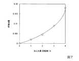
図7は、増幅用光ファイバのねじれ量とM2増加量との関係を示すグラフである。図7の横軸は増幅用光ファイバ1mあたりのねじれ量(増幅用光ファイバの中心軸に垂直な断面における円周方向の回転数)であり、図7の縦軸は増幅用光ファイバがねじれていないときのM2値に対するM2増加量である。The inventor examined the relationship between the twist amount of the amplification optical fiber and the change in the M2 value. The results are shown below.
FIG. 7 is a graph showing the relationship between the twist amount of the amplification optical fiber and the M2 increase amount. The horizontal axis in FIG. 7 is the amount of twist per 1 m of the amplification optical fiber (the number of rotations in the circumferential direction in the cross section perpendicular to the central axis of the amplification optical fiber), and the vertical axis in FIG. This is the amount of increase in M2 relative to the M2 value when not.
図7に示す通り、増幅用光ファイバ1mあたりのねじれ量が多くなるにつれて、M2増加量は急激に増加する傾向を示す。このグラフから、増幅用光ファイバ1mあたりのねじれ量が3回転以下であれば、M2増加量は0.01以下となる。M2値の理想値は1であるため、M2増加量が0.01以下であれば、理想値に対する割合としてM2値の増加分が1%以下となり、ビーム品質として安定していると判断することができる。As shown in FIG. 7, the amount of increase in M2 tends to increase rapidly as the amount of twist per 1 m of optical fiber for amplification increases. From this graph, if the twist amount per 1 m of the amplification optical fiber is 3 rotations or less, the increase amount of M2 is 0.01 or less. Since the ideal value of the M2 value is 1, if the M2 increase is 0.01 or less, the increase of the M2 value is 1% or less as a ratio to the ideal value, and the beam quality is stable. Judgment can be made.
上述したように、増幅用光ファイバ25のねじれ量が一定でなく、増幅用光ファイバ25の第2の反射部23に近い部位のねじれ量が、増幅用光ファイバ25の第1の反射部22に近い部位のねじれ量よりも大きくてもよい。すなわち、増幅用光ファイバ25の出力側のねじれ量が、増幅用光ファイバ25の入力側のねじれ量よりも大きくてもよい。通常、増幅用光ファイバにおいて、励起光は主に入力側(第1の反射部側)でコアに多く吸収され、出力側(第2の反射部側)に向かうにつれて多くのスキュー光成分が発生する傾向にある。その点、上記の構成によれば、増幅用光ファイバ25のねじれ量が、第1の反射部22側から第2の反射部23側に向かうにつれて大きくなっているため、スキュー光成分が出力側のコアにより吸収されやすくなる。これにより、局所的な発熱を抑制しつつ、増幅用光ファイバ25のビーム品質の低下を抑え、かつ、励起光の利用効率を高めることができる。 As described above, the twist amount of the amplification
[第2実施形態]
以下、本発明の第2実施形態について、図8を用いて説明する。
第2実施形態のファイバレーザ装置の構成は第1実施形態のファイバレーザ装置と同様であり、増幅用コイルの製造方法が第1実施形態と異なる。したがって、本実施形態では、増幅用コイルの他の製造方法について説明する。[Second Embodiment]
Hereinafter, a second embodiment of the present invention will be described with reference to FIG.
The configuration of the fiber laser device of the second embodiment is the same as that of the fiber laser device of the first embodiment, and the manufacturing method of the amplifying coil is different from that of the first embodiment. Therefore, in the present embodiment, another method for manufacturing the amplification coil will be described.
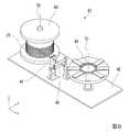
図8は、本実施形態の増幅用コイルの製造方法に用いるコイル自動巻装置を示す斜視図である。
図8において、ボビンと回転治具とが配列された方向をx軸方向とし、ボビンと回転治具の配列方向に直交する方向をy軸方向とし、コイル自動巻装置の高さ方向(鉛直方向)をz軸方向とする。FIG. 8 is a perspective view showing an automatic coil winding device used in the method of manufacturing an amplification coil according to this embodiment.
In FIG. 8, the direction in which the bobbin and the rotating jig are arranged is the x-axis direction, the direction orthogonal to the direction in which the bobbin and the rotating jig are arranged is the y-axis direction, and the height direction (vertical direction) of the coil automatic winding device ) Is the z-axis direction.
図8に示すように、コイル自動巻装置41は、基台42と、ボビン43と、回転治具44と、第1ファイバガイドコロ45と、第2ファイバガイドコロ46と、を備えている。基台42は、ボビン43、回転治具44、第1ファイバガイドコロ45および第2ファイバガイドコロ46等の部材を支持する。ボビン43は、増幅用コイル21を製作する前の増幅用光ファイバ25が巻回されたものである。回転治具44は、ボビン43から引き出された増幅用光ファイバ25を巻き取って増幅用コイル21を製作するものである。第1ファイバガイドコロ45および第2ファイバガイドコロ46は、ボビン43と回転治具44との間で増幅用光ファイバ25を支持するものである。 As shown in FIG. 8, the coil automatic winding
ボビン43と回転治具44とは、モーター等の駆動源(図示略)により自動的に回転する構成となっている。また、ボビン43の回転軸Cbと回転治具44の回転軸Cjとは、これら2本の回転軸Cb,Cjの配列方向と直交する平面内(yz平面内)においてねじれた位置関係にあり、非平行に配置されている。 The
最初に、増幅用光ファイバ25が巻回されたボビン43をコイル自動巻装置41にセットする。
次に、増幅用光ファイバ25の先端を引き出し、第1ファイバガイドコロ45および第2ファイバガイドコロ46を介して回転治具44に接続する。
次に、コイル自動巻装置41の電源スイッチをONとする。これにより、ボビン43と回転治具44とが自動的に回転し、増幅用光ファイバ25は回転治具44の内側から外側に向けて巻回されていく。このとき、ボビン43の回転軸Cbと回転治具44の回転軸Cjとがねじれた位置関係にあるため、増幅用光ファイバ25は、自身の中心軸を中心として周方向にねじれつつ回転治具44に巻回される。First, the
Next, the tip of the amplification
Next, the power switch of the automatic
次に、増幅用光ファイバ25がねじられて巻回された状態を保持するため、テープを用いて増幅用光ファイバ25同士を仮固定する。
次に、巻回された状態の増幅用光ファイバ25から回転治具44を取り外す。Next, in order to maintain the state in which the amplification
Next, the rotating
次に、巻回された増幅用光ファイバ25にシリコーンゴム系の樹脂を塗布し、隣り合う増幅用光ファイバ25の間に樹脂を充填させる。樹脂を塗布した後、所定時間放置して樹脂を硬化させる。これにより、巻回した増幅用光ファイバ25を互いに固定し、一体化する。
以上の工程により、増幅用コイル21が完成する。Next, a silicone rubber-based resin is applied to the wound amplification
The
本実施形態においても、取り扱いが容易であり、かつ、特性に優れた増幅用コイルを備えたファイバレーザ装置を提供できる、という第1実施形態と同様の効果が得られる。さらに本実施形態の場合、コイル自動巻装置41を用いて増幅用コイル21を製作するため、ボビン43の回転軸Cbと回転治具44の回転軸Cjとのねじれ角を調整することにより増幅用光ファイバ25のねじれ量を制御できる、という効果が得られる。例えば、ボビン43の回転軸Cbと回転治具44の回転軸Cjとのねじれ角を、巻き取り開始時から徐々に大きくしていくと、内側から外側に向けて増幅用光ファイバ25のねじれ量が徐々に大きくなるコイルを製作できる。この場合、コイルの内側を第1の反射部側(入力側)、コイルの外側を第2の反射部側(出力側)に接続すればよい。 In this embodiment, the same effect as that of the first embodiment can be obtained that the fiber laser device including the amplification coil that is easy to handle and has excellent characteristics can be provided. Further, in the case of the present embodiment, since the amplifying
なお、本発明の技術範囲は上記実施形態に限定されるものではなく、本発明の趣旨を逸脱しない範囲において種々の変更を加えることが可能である。
例えば上記実施形態では、平面状に巻回された1層の増幅用光ファイバからなる増幅用コイルの例を示した。この構成に代えて、コイルの放熱性は劣るものの、例えば図9に示すように、増幅用光ファイバ25が径方向と垂直な方向に複数層積み重ねられた増幅用コイル51が用いられてもよい。The technical scope of the present invention is not limited to the above embodiment, and various modifications can be made without departing from the spirit of the present invention.
For example, in the above-described embodiment, an example of an amplifying coil including a single layer of amplifying optical fiber wound in a planar shape has been described. Instead of this configuration, although the heat dissipation of the coil is inferior, for example, as shown in FIG. 9, an
上記実施形態では、樹脂が増幅用コイルの全周にわたって設けられている構成の一例を示した。この構成に代えて、樹脂は、必ずしも増幅用コイルの全周にわたって設けられていなくてもよく、増幅用コイルを周方向に分割した一部の領域のみに設けられていてもよい。この構成は、例えば、巻回された増幅用光ファイバをテープで仮固定し、テープで覆われた領域以外の領域に樹脂を塗布し、硬化させた後、テープを剥離するプロセスによって実現が可能である。 In the above embodiment, an example of a configuration in which the resin is provided over the entire circumference of the amplification coil has been described. Instead of this configuration, the resin does not necessarily have to be provided over the entire circumference of the amplification coil, and may be provided only in a partial region obtained by dividing the amplification coil in the circumferential direction. This configuration can be realized, for example, by a process in which the wound amplification optical fiber is temporarily fixed with a tape, a resin is applied to an area other than the area covered with the tape and cured, and then the tape is peeled off. It is.
また、上記実施形態では、樹脂を用いて、隣り合う増幅用光ファイバを互いに固定して一体化した例を挙げたが、この構成に代えて、例えばコイル状の溝が設けられた治具を用い、治具の溝に増幅用光ファイバを嵌め込むことにより、増幅用光ファイバを固定して一体化してもよい。すなわち、隣り合う増幅用光ファイバは、他の部材を介して固定されていてもよく、必ずしも増幅用光ファイバ同士が互いに固定されて一体化されていなくてもよい。
その他、ファイバレーザ装置の各構成要素の形状、寸法、配置、材料等に関する具体的な記載は、上記実施形態に限らず、適宜変更が可能である。In the above embodiment, an example is described in which adjacent amplification optical fibers are fixed and integrated with each other using a resin. Instead of this configuration, for example, a jig provided with a coiled groove is used. Alternatively, the amplification optical fiber may be fixed and integrated by fitting the amplification optical fiber into the groove of the jig. That is, the adjacent amplification optical fibers may be fixed via other members, and the amplification optical fibers are not necessarily fixed and integrated with each other.
In addition, the specific description regarding the shape, size, arrangement, material, and the like of each component of the fiber laser device is not limited to the above-described embodiment, and can be appropriately changed.
本発明は、例えば材料加工等に用いるファイバレーザ装置、および増幅用コイルの製造方法に利用が可能である。 The present invention can be used in, for example, a fiber laser device used for material processing and a method for manufacturing an amplification coil.
1…ファイバレーザ装置、11…励起用レーザダイオード(励起用光源)、13…光共振器、21,51…増幅用コイル、22…第1の反射部、23…第2の反射部、24…水冷板(冷却用部材)25…増幅用光ファイバ、26…樹脂、28…コア、29…第1クラッド、30…第2クラッド、41…コイル自動巻装置、43…ボビン、44…回転治具。 DESCRIPTION OF
Claims (7)
Translated fromJapanese前記光共振器は、コアと非円形クラッドとを含む増幅用光ファイバが巻回された構成を有する増幅用コイルと、
前記レーザ光を反射させる第1の反射部と、
前記第1の反射部の反射率よりも低い反射率を有し、前記レーザ光を反射させる第2の反射部と、を備え、
前記増幅用光ファイバは、前記増幅用光ファイバの中心軸を中心として前記増幅用光ファイバの周方向にねじられた状態で巻回され、巻回された前記増幅用光ファイバが固定されて一体化され、
前記増幅用光ファイバのねじれ量が、前記第1の反射部側から前記第2の反射部側に向かうにつれて大きくなる
ことを特徴とするファイバレーザ装置。An excitation light source and an optical resonator that resonates the laser beam,
The optical resonator includes an amplification coil having a configuration in which an amplification optical fiber including a core and a non-circular cladding is wound;
A first reflecting part for reflecting the laser beam;
A second reflecting portion that has a reflectance lower than the reflectance of the first reflecting portion and reflects the laser light,
The amplification optical fiber is wound in a state twisted in the circumferential direction of the amplification optical fiber around the central axis of the amplification optical fiber, and the wound amplification optical fiber is fixed and integrated.ized,
The twisting amount of the amplification optical fiber increases from the first reflecting portion side toward the second reflecting portion side.
Fiber laser device, characterized inthat.
前記光共振器は、コアと非円形クラッドとを含む増幅用光ファイバが巻回された構成を有する増幅用コイルと、 The optical resonator includes an amplification coil having a configuration in which an amplification optical fiber including a core and a non-circular cladding is wound;
前記レーザ光を反射させる第1の反射部と、 A first reflecting part for reflecting the laser beam;
前記第1の反射部の反射率よりも低い反射率を有し、前記レーザ光を反射させる第2の反射部と、を備え、 A second reflecting portion that has a reflectance lower than the reflectance of the first reflecting portion and reflects the laser light,
前記増幅用光ファイバは、前記増幅用光ファイバの中心軸を中心として前記増幅用光ファイバの周方向にねじられた状態で巻回され、巻回された前記増幅用光ファイバが固定されて一体化され、 The amplification optical fiber is wound in a state twisted in the circumferential direction of the amplification optical fiber around the central axis of the amplification optical fiber, and the wound amplification optical fiber is fixed and integrated. And
隣り合う前記増幅用光ファイバの間に樹脂が充填され、且つ平面視で隣り合う前記増幅用光ファイバの間に隙間がある、 Resin is filled between the adjacent amplification optical fibers, and there is a gap between the amplification optical fibers adjacent in a plan view.
ことを特徴とするファイバレーザ装置。 A fiber laser device.
前記光共振器は、コアと非円形クラッドとを含む増幅用光ファイバが巻回された構成を有する増幅用コイルと、 The optical resonator includes an amplification coil having a configuration in which an amplification optical fiber including a core and a non-circular cladding is wound;
前記レーザ光を反射させる第1の反射部と、 A first reflecting part for reflecting the laser beam;
前記第1の反射部の反射率よりも低い反射率を有し、前記レーザ光を反射させる第2の反射部と、を備え、 A second reflecting portion that has a reflectance lower than the reflectance of the first reflecting portion and reflects the laser light,
前記増幅用光ファイバは、前記増幅用光ファイバの中心軸を中心として前記増幅用光ファイバの周方向にねじられた状態で巻回され、巻回された前記増幅用光ファイバが固定されて一体化され、 The amplification optical fiber is wound in a state twisted in the circumferential direction of the amplification optical fiber around the central axis of the amplification optical fiber, and the wound amplification optical fiber is fixed and integrated. And
前記増幅用光ファイバの巻き径が、前記第1の反射部側から前記第2の反射部側に向かうにつれて小さくなる The winding diameter of the amplification optical fiber decreases from the first reflecting portion side toward the second reflecting portion side.
ことを特徴とするファイバレーザ装置。 A fiber laser device.
隣り合う前記増幅用光ファイバの間に樹脂を充填させることにより前記増幅用光ファイバを互いに固定する工程と、を備えたことを特徴とする増幅用コイルの製造方法。Winding the amplification optical fiber in a coil while lowering a part of the amplification optical fiber on a base;
And a step of fixing the amplification optical fibers to each other by filling a resin between the adjacent amplification optical fibers.
隣り合う前記増幅用光ファイバの間に樹脂を充填させることにより前記増幅用光ファイバを互いに固定する工程と、を備え、
前記増幅用光ファイバをコイル状に巻回する工程において、前記ボビンの回転軸と前記回転治具の回転軸とを非平行に配置することを特徴とする増幅用コイルの製造方法。A step of winding the coil the amplification optical fiber by winding theamplification optical fiberdrawn from the bobbin to the rotation jig,
Fixing the amplification optical fibers to each other by filling a resin between the adjacent amplification optical fibers, and
In the step of winding the amplification optical fiber in a coil shape, the rotating shaft of the bobbin and the rotating shaft of the rotating jig are arranged non-parallel to each other.
Priority Applications (5)
| Application Number | Priority Date | Filing Date | Title |
|---|---|---|---|
| JP2015025184AJP6140743B2 (en) | 2015-02-12 | 2015-02-12 | Fiber laser device and method for manufacturing amplification coil |
| PCT/JP2016/053014WO2016129447A1 (en) | 2015-02-12 | 2016-02-02 | Fiber laser device and manufacturing method for amplification coil |
| CN201680002392.2ACN106663911B (en) | 2015-02-12 | 2016-02-02 | Optical fiber laser device and method for manufacturing coil for amplification |
| EP16749091.1AEP3196992A4 (en) | 2015-02-12 | 2016-02-02 | Fiber laser device and manufacturing method for amplification coil |
| US15/444,548US10530113B2 (en) | 2015-02-12 | 2017-02-28 | Fiber laser apparatus and method of manufacturing amplifying coil |
Applications Claiming Priority (1)
| Application Number | Priority Date | Filing Date | Title |
|---|---|---|---|
| JP2015025184AJP6140743B2 (en) | 2015-02-12 | 2015-02-12 | Fiber laser device and method for manufacturing amplification coil |
Publications (2)
| Publication Number | Publication Date |
|---|---|
| JP2016149432A JP2016149432A (en) | 2016-08-18 |
| JP6140743B2true JP6140743B2 (en) | 2017-05-31 |
Family
ID=56614636
Family Applications (1)
| Application Number | Title | Priority Date | Filing Date |
|---|---|---|---|
| JP2015025184AActiveJP6140743B2 (en) | 2015-02-12 | 2015-02-12 | Fiber laser device and method for manufacturing amplification coil |
Country Status (5)
| Country | Link |
|---|---|
| US (1) | US10530113B2 (en) |
| EP (1) | EP3196992A4 (en) |
| JP (1) | JP6140743B2 (en) |
| CN (1) | CN106663911B (en) |
| WO (1) | WO2016129447A1 (en) |
Families Citing this family (15)
| Publication number | Priority date | Publication date | Assignee | Title |
|---|---|---|---|---|
| JP2016171208A (en)* | 2015-03-12 | 2016-09-23 | 株式会社フジクラ | Optical fiber, fiber amplifier, and fiber laser |
| US10447004B2 (en) | 2015-11-19 | 2019-10-15 | Nlight, Inc. | Laser fault tolerance and self-calibration system |
| CN109478755B (en)* | 2016-06-30 | 2021-02-02 | 株式会社藤仓 | Optical fiber and laser device for amplification |
| US10620369B2 (en) | 2016-06-30 | 2020-04-14 | Fujikura Ltd. | Amplification optical fiber and laser device |
| CN109845052B (en) | 2016-08-31 | 2022-01-11 | 恩耐公司 | Laser cooling system |
| US11347069B2 (en) | 2016-11-22 | 2022-05-31 | Lumentum Operations Llc | Rotary optical beam generator |
| US10429584B2 (en)* | 2016-11-22 | 2019-10-01 | Lumentum Operations Llc | Rotary optical beam generator |
| JPWO2018003574A1 (en)* | 2016-12-05 | 2019-03-28 | 株式会社フジクラ | Amplifying optical fiber and laser device |
| WO2018112220A1 (en)* | 2016-12-15 | 2018-06-21 | Nlight, Inc. | Fiber laser packaging |
| JP2019078798A (en)* | 2017-10-20 | 2019-05-23 | 株式会社フジクラ | Optical device, fiber laser system, and method for manufacturing fiber laser system |
| WO2019178003A1 (en) | 2018-03-12 | 2019-09-19 | Nlight, Inc. | Fiber laser having variably wound optical fiber |
| JP2020136525A (en)* | 2019-02-21 | 2020-08-31 | 株式会社フジクラ | Optical component and laser device |
| US10804871B1 (en) | 2019-05-14 | 2020-10-13 | Honeywell International Inc. | Cryogenic radio-frequency resonator for surface ion traps |
| CN114846701B (en)* | 2020-04-15 | 2025-02-25 | 株式会社藤仓 | Optical devices and fiber laser devices |
| CN119496021A (en)* | 2024-11-06 | 2025-02-21 | 长飞光坊(武汉)科技有限公司 | A multi-clad active optical fiber and a method for preparing the same |
Family Cites Families (39)
| Publication number | Priority date | Publication date | Assignee | Title |
|---|---|---|---|---|
| GB2127869B (en)* | 1982-09-22 | 1986-04-30 | Standard Telephones Cables Ltd | Optical fibre cable manufacture |
| IT1238162B (en)* | 1990-01-12 | 1993-07-09 | DETORTION REELING MACHINE, ESPECIALLY FOR THE FORMATION OF OPTICAL FIBER BUNCHES | |
| US5949941A (en)* | 1997-11-21 | 1999-09-07 | Lucent Technologies Inc. | Cladding-pumped fiber structures |
| EP0933841B1 (en)* | 1998-01-30 | 2005-04-06 | Hoya Corporation | Fiber laser |
| US6546180B1 (en)* | 1999-01-06 | 2003-04-08 | Sumitomo Electric Industries, Ltd. | Coiled optical assembly and fabricating method for the same |
| EP1175714B1 (en)* | 1999-04-30 | 2009-01-07 | SPI Lasers UK Limited | Method of producing an amplifying optical fibre device |
| JP2001013346A (en)* | 1999-06-29 | 2001-01-19 | Furukawa Electric Co Ltd:The | Double clad fiber, optical amplifier and fiber laser using the same |
| US6384919B1 (en)* | 1999-10-29 | 2002-05-07 | Northrop Grumman Corporation | Fiber optic seismic sensor |
| JP4369576B2 (en)* | 1999-11-25 | 2009-11-25 | 浜松ホトニクス株式会社 | Laser device manufacturing method, laser processing device manufacturing method, and optical amplifier manufacturing method |
| JP4401540B2 (en)* | 2000-06-30 | 2010-01-20 | 浜松ホトニクス株式会社 | Laser apparatus and optical signal amplifying apparatus using the same |
| TWI226464B (en)* | 2000-11-13 | 2005-01-11 | Sumitomo Electric Industries | Optical fiber, non-linear optical fiber, optical amplifier using the same optical fiber, wavelength converter and optical fiber manufacture method |
| JP4683863B2 (en)* | 2003-06-19 | 2011-05-18 | インベンテイオ・アクテイエンゲゼルシヤフト | Elevator for load transportation by movable traction means |
| US20050024716A1 (en)* | 2003-07-15 | 2005-02-03 | Johan Nilsson | Optical device with immediate gain for brightness enhancement of optical pulses |
| JP2005200277A (en)* | 2004-01-16 | 2005-07-28 | Toyoda Mach Works Ltd | Method for manufacturing optical fiber |
| US7724422B2 (en)* | 2004-01-30 | 2010-05-25 | Nufern | Method and apparatus for providing light having a selected polarization with an optical fiber |
| JP2006019490A (en)* | 2004-07-01 | 2006-01-19 | Toyoda Mach Works Ltd | Fiber laser oscillator |
| JP2006093613A (en) | 2004-09-27 | 2006-04-06 | Sumitomo Electric Ind Ltd | Optical fiber, optical fiber amplifier, and optical fiber laser light source |
| JP2006114769A (en)* | 2004-10-15 | 2006-04-27 | Mitsubishi Cable Ind Ltd | Optical amplifier |
| JP2007273600A (en)* | 2006-03-30 | 2007-10-18 | Furukawa Electric Co Ltd:The | Optical fiber laser |
| US7477806B2 (en)* | 2006-04-28 | 2009-01-13 | Morgan Research Corporation | Crossover-free fiber optic coil sensor and winding method |
| JP5089950B2 (en)* | 2006-05-30 | 2012-12-05 | 株式会社フジクラ | Multi-port coupler, optical amplifier and fiber laser |
| EP2078327A1 (en)* | 2006-10-18 | 2009-07-15 | The Commonwealth Of Australia | Cascade laser |
| JP5086822B2 (en)* | 2007-01-31 | 2012-11-28 | パナソニック株式会社 | Wavelength conversion device and two-dimensional image display device |
| JPWO2008133242A1 (en)* | 2007-04-25 | 2010-07-29 | 株式会社フジクラ | Rare earth doped core optical fiber |
| EP2201415B1 (en)* | 2007-09-26 | 2019-07-03 | Imra America, Inc. | Glass large-core optical fibers |
| JP4579283B2 (en) | 2007-11-20 | 2010-11-10 | 日立電線株式会社 | Optical fiber laser and optical fiber laser excitation method |
| JP5649973B2 (en)* | 2007-12-14 | 2015-01-07 | ロフィン−ジナール レーザー ゲゼルシャフト ミット ベシュレンクテル ハフツング | Optical coupling means to optical fiber and coupler manufacturing method |
| CA2712123C (en)* | 2008-01-17 | 2014-12-23 | Institut National D'optique | Multi-cladding optical fiber with mode filtering through differential bending losses |
| US8213077B2 (en)* | 2008-04-22 | 2012-07-03 | Imra America, Inc. | Multi-clad optical fibers |
| US8340482B2 (en)* | 2009-03-31 | 2012-12-25 | Furukawa Electric Co., Ltd. | Optical fiber holding apparatus |
| KR101747153B1 (en)* | 2009-05-11 | 2017-06-14 | 오에프에스 피텔 엘엘씨 | Filter fiber for use in raman lasing applications and techniques for manufacturing same |
| JP4663804B2 (en)* | 2009-09-04 | 2011-04-06 | 株式会社フジクラ | Fiber laser equipment |
| JP5691236B2 (en)* | 2010-04-30 | 2015-04-01 | 住友電気工業株式会社 | Multi-core optical fiber and single-core separation method of multi-core optical fiber |
| WO2012056566A1 (en)* | 2010-10-29 | 2012-05-03 | 古河電気工業株式会社 | Optical amplifier device and optical transmission system |
| US9507084B2 (en)* | 2010-12-03 | 2016-11-29 | Ofs Fitel, Llc | Single-mode, bend-compensated, large-mode-area optical fibers designed to accomodate simplified fabrication and tighter bends |
| US9083140B2 (en)* | 2011-03-10 | 2015-07-14 | Coherent, Inc. | High-power CW fiber-laser |
| US8958074B1 (en)* | 2012-08-27 | 2015-02-17 | The Boeing Company | Low strain optical fiber coil and associated fiber optic gyroscope and method |
| US9366810B2 (en)* | 2012-08-29 | 2016-06-14 | Ofs Fitel, Llc | Double-clad, gain-producing fibers with increased cladding absoroption while maintaining single-mode operation |
| US9606311B2 (en)* | 2013-12-18 | 2017-03-28 | Raytheon Company | Thermal management for high-power optical fibers |
- 2015
- 2015-02-12JPJP2015025184Apatent/JP6140743B2/enactiveActive
- 2016
- 2016-02-02CNCN201680002392.2Apatent/CN106663911B/enactiveActive
- 2016-02-02EPEP16749091.1Apatent/EP3196992A4/ennot_activeWithdrawn
- 2016-02-02WOPCT/JP2016/053014patent/WO2016129447A1/ennot_activeCeased
- 2017
- 2017-02-28USUS15/444,548patent/US10530113B2/enactiveActive
Also Published As
| Publication number | Publication date |
|---|---|
| JP2016149432A (en) | 2016-08-18 |
| WO2016129447A1 (en) | 2016-08-18 |
| CN106663911B (en) | 2020-02-14 |
| US10530113B2 (en) | 2020-01-07 |
| EP3196992A4 (en) | 2018-08-08 |
| EP3196992A1 (en) | 2017-07-26 |
| CN106663911A (en) | 2017-05-10 |
| US20170170622A1 (en) | 2017-06-15 |
Similar Documents
| Publication | Publication Date | Title |
|---|---|---|
| JP6140743B2 (en) | Fiber laser device and method for manufacturing amplification coil | |
| JP5390524B2 (en) | Active optical fiber and method of making active optical fiber | |
| JP6306624B2 (en) | Fiber that provides double-clad gain with increased cladding absorption while maintaining single-mode operation | |
| JP5662151B2 (en) | Glass large core optical fiber | |
| JP6113748B2 (en) | Bending compensation filter fiber | |
| US20170162999A1 (en) | Optical mode filter employing radially asymmetric fiber | |
| JP4452756B2 (en) | Photonic bandgap fiber | |
| CN109478755B (en) | Optical fiber and laser device for amplification | |
| JP6255532B1 (en) | Amplifying optical fiber and laser device | |
| JP2008273769A (en) | Optical fiber, manufacturing method thereof, and optical fiber manufacturing apparatus | |
| JP4579283B2 (en) | Optical fiber laser and optical fiber laser excitation method | |
| JP2005019539A (en) | Rare earth doped fiber and optical fiber laser using the same | |
| WO2010103764A1 (en) | Fiber laser device and light amplifying method | |
| JP6744074B2 (en) | Optical fiber for optical fiber grating and fiber laser device | |
| JP6306636B2 (en) | Fiber that provides gain with increased cladding absorption while maintaining single mode operation | |
| JP6666882B2 (en) | Method of manufacturing single-core optical fiber preform and method of manufacturing single-core optical fiber | |
| JP2019077598A (en) | Optical fiber manufacturing method | |
| JP2008308361A (en) | Optical fiber and manufacturing method thereof | |
| JP6018435B2 (en) | Double clad optical fiber | |
| CN102570253A (en) | Disc type waveguide laser | |
| JP7495804B2 (en) | Active element doped optical fiber, resonator, and fiber laser device | |
| JP2005200277A (en) | Method for manufacturing optical fiber | |
| US20090316733A1 (en) | Optical fiber for a fiber laser and fiber laser using the same | |
| JPWO2018003574A1 (en) | Amplifying optical fiber and laser device | |
| JP2020136525A (en) | Optical component and laser device |
Legal Events
| Date | Code | Title | Description |
|---|---|---|---|
| A131 | Notification of reasons for refusal | Free format text:JAPANESE INTERMEDIATE CODE: A131 Effective date:20161004 | |
| A521 | Request for written amendment filed | Free format text:JAPANESE INTERMEDIATE CODE: A523 Effective date:20161108 | |
| TRDD | Decision of grant or rejection written | ||
| A01 | Written decision to grant a patent or to grant a registration (utility model) | Free format text:JAPANESE INTERMEDIATE CODE: A01 Effective date:20170404 | |
| A61 | First payment of annual fees (during grant procedure) | Free format text:JAPANESE INTERMEDIATE CODE: A61 Effective date:20170501 | |
| R151 | Written notification of patent or utility model registration | Ref document number:6140743 Country of ref document:JP Free format text:JAPANESE INTERMEDIATE CODE: R151 | |
| R250 | Receipt of annual fees | Free format text:JAPANESE INTERMEDIATE CODE: R250 | |
| R250 | Receipt of annual fees | Free format text:JAPANESE INTERMEDIATE CODE: R250 | |
| R250 | Receipt of annual fees | Free format text:JAPANESE INTERMEDIATE CODE: R250 | |
| R250 | Receipt of annual fees | Free format text:JAPANESE INTERMEDIATE CODE: R250 | |
| R250 | Receipt of annual fees | Free format text:JAPANESE INTERMEDIATE CODE: R250 | |
| R250 | Receipt of annual fees | Free format text:JAPANESE INTERMEDIATE CODE: R250 |