JP6138879B2 - Handheld color cutting tool - Google Patents
Handheld color cutting toolDownload PDFInfo
- Publication number
- JP6138879B2 JP6138879B2JP2015172668AJP2015172668AJP6138879B2JP 6138879 B2JP6138879 B2JP 6138879B2JP 2015172668 AJP2015172668 AJP 2015172668AJP 2015172668 AJP2015172668 AJP 2015172668AJP 6138879 B2JP6138879 B2JP 6138879B2
- Authority
- JP
- Japan
- Prior art keywords
- endoscope
- balloon
- collar
- sleeve
- assembly
- Prior art date
- Legal status (The legal status is an assumption and is not a legal conclusion. Google has not performed a legal analysis and makes no representation as to the accuracy of the status listed.)
- Expired - Fee Related
Links
- 238000000034methodMethods0.000claimsdescription19
- 125000006850spacer groupChemical group0.000claimsdescription13
- 238000010586diagramMethods0.000description20
- ORQBXQOJMQIAOY-UHFFFAOYSA-NnobeliumChemical compound[No]ORQBXQOJMQIAOY-UHFFFAOYSA-N0.000description20
- 238000006073displacement reactionMethods0.000description11
- 239000000463materialSubstances0.000description10
- 239000000853adhesiveSubstances0.000description9
- 230000001070adhesive effectEffects0.000description9
- 229920000126latexPolymers0.000description8
- 239000004816latexSubstances0.000description8
- 210000000813small intestineAnatomy0.000description8
- 239000004677NylonSubstances0.000description6
- 238000004873anchoringMethods0.000description6
- 229920001778nylonPolymers0.000description6
- 229920001296polysiloxanePolymers0.000description6
- 238000007789sealingMethods0.000description6
- 230000008602contractionEffects0.000description5
- 238000003780insertionMethods0.000description5
- 230000037431insertionEffects0.000description5
- 229920002635polyurethanePolymers0.000description5
- 239000004814polyurethaneSubstances0.000description5
- XUIMIQQOPSSXEZ-UHFFFAOYSA-NSiliconChemical compound[Si]XUIMIQQOPSSXEZ-UHFFFAOYSA-N0.000description4
- 238000001727in vivoMethods0.000description4
- 229910052710siliconInorganic materials0.000description4
- 239000010703siliconSubstances0.000description4
- 229920006362Teflon®Polymers0.000description3
- 239000011248coating agentSubstances0.000description3
- 238000000576coating methodMethods0.000description3
- 210000002429large intestineAnatomy0.000description3
- 230000002093peripheral effectEffects0.000description3
- 238000011179visual inspectionMethods0.000description3
- 229920002614Polyether block amidePolymers0.000description2
- 238000001839endoscopyMethods0.000description2
- 239000002783friction materialSubstances0.000description2
- 239000002210silicon-based materialSubstances0.000description2
- 230000007704transitionEffects0.000description2
- 229920004943Delrin®Polymers0.000description1
- 241000566576TytoSpecies0.000description1
- 210000001367arteryAnatomy0.000description1
- 238000004891communicationMethods0.000description1
- 238000010276constructionMethods0.000description1
- 239000013013elastic materialSubstances0.000description1
- 229920001971elastomerPolymers0.000description1
- 239000012530fluidSubstances0.000description1
- 238000009434installationMethods0.000description1
- 210000000936intestineAnatomy0.000description1
- 239000002184metalSubstances0.000description1
- 238000012986modificationMethods0.000description1
- 230000004048modificationEffects0.000description1
- 239000004033plasticSubstances0.000description1
- 229920003023plasticPolymers0.000description1
- 238000003825pressingMethods0.000description1
- 239000005060rubberSubstances0.000description1
- 229910001220stainless steelInorganic materials0.000description1
- 239000010935stainless steelSubstances0.000description1
- 210000003462veinAnatomy0.000description1
- 238000003466weldingMethods0.000description1
Images


Classifications
- A—HUMAN NECESSITIES
- A61—MEDICAL OR VETERINARY SCIENCE; HYGIENE
- A61B—DIAGNOSIS; SURGERY; IDENTIFICATION
- A61B1/00—Instruments for performing medical examinations of the interior of cavities or tubes of the body by visual or photographical inspection, e.g. endoscopes; Illuminating arrangements therefor
- A61B1/00064—Constructional details of the endoscope body
- A61B1/00071—Insertion part of the endoscope body
- A61B1/0008—Insertion part of the endoscope body characterised by distal tip features
- A61B1/00082—Balloons
- A—HUMAN NECESSITIES
- A61—MEDICAL OR VETERINARY SCIENCE; HYGIENE
- A61B—DIAGNOSIS; SURGERY; IDENTIFICATION
- A61B1/00—Instruments for performing medical examinations of the interior of cavities or tubes of the body by visual or photographical inspection, e.g. endoscopes; Illuminating arrangements therefor
- A61B1/00064—Constructional details of the endoscope body
- A61B1/00071—Insertion part of the endoscope body
- A61B1/0008—Insertion part of the endoscope body characterised by distal tip features
- A61B1/00101—Insertion part of the endoscope body characterised by distal tip features the distal tip features being detachable
- A—HUMAN NECESSITIES
- A61—MEDICAL OR VETERINARY SCIENCE; HYGIENE
- A61B—DIAGNOSIS; SURGERY; IDENTIFICATION
- A61B1/00—Instruments for performing medical examinations of the interior of cavities or tubes of the body by visual or photographical inspection, e.g. endoscopes; Illuminating arrangements therefor
- A61B1/00131—Accessories for endoscopes
- A61B1/00135—Oversleeves mounted on the endoscope prior to insertion
Landscapes
- Health & Medical Sciences (AREA)
- Life Sciences & Earth Sciences (AREA)
- Surgery (AREA)
- Biomedical Technology (AREA)
- Medical Informatics (AREA)
- Optics & Photonics (AREA)
- Pathology (AREA)
- Radiology & Medical Imaging (AREA)
- Biophysics (AREA)
- Engineering & Computer Science (AREA)
- Physics & Mathematics (AREA)
- Heart & Thoracic Surgery (AREA)
- Nuclear Medicine, Radiotherapy & Molecular Imaging (AREA)
- Molecular Biology (AREA)
- Animal Behavior & Ethology (AREA)
- General Health & Medical Sciences (AREA)
- Public Health (AREA)
- Veterinary Medicine (AREA)
- Endoscopes (AREA)
- Instruments For Viewing The Inside Of Hollow Bodies (AREA)
Description
Translated fromJapanese関連出願の相互参照
開示内容が参照によって本明細書に組み込まれ、米国特許法施行規則第1.78条(a)(4)および(5)(i)に従ってその優先権が本明細書に主張されている以下の関連出願:
米国仮特許出願第61/064,881号、出願日2008年3月31日、発明の名称“DEVICE AND METHOD FOR EXPANDABLE ELEMENT”
が参照される。CROSS REFERENCE TO RELATED APPLICATIONS The disclosure is incorporated herein by reference and claimed herein in accordance with 37 CFR 1.78 (a) (4) and (5) (i). The following related applications are:
US provisional patent application No. 61 / 064,881, filed March 31, 2008, title of invention “DEVICE AND METHOD FOR EXPANDABLE ELEMENT”
Is referenced.
本出願人の同時係属中の、2005年2月7日出願のPCT出願番号PCT/IL2005/000152と、2007年5月17日付け出願のPCT出願番号PCT/IL2007/000600と、2007年7月4日付け出願のPCT出願番号PCT/IL2007/00832とがさらに参照され、それらの開示内容が参照によって本明細書に組み込まれる。 Applicant's co-pending PCT application number PCT / IL2005 / 000152 filed February 7, 2005, PCT application number PCT / IL2007 / 000600 filed May 17, 2007, July 2007 Reference is further made to the 4-date application PCT application number PCT / IL2007 / 00832, the disclosures of which are incorporated herein by reference.
発明の分野
本発明は一般に内視鏡システムに関する。The present invention relates generally to endoscope systems.
以下の特許公報および市販製品が現在の最先端技術を表していると考えられる。 The following patent publications and commercial products are considered to represent the current state of the art.
米国特許公報である特許文献1、特許文献2、特許文献3、特許文献4、特許文献5、特許文献6、特許文献7、特許文献8、特許文献9、特許文献10、特許文献11。
米国特許出願公開公報である特許文献12、特許文献13、特許文献14、特許文献15、特許文献16、特許文献17、特許文献18、特許文献19。 Patent Literature 12, Patent Literature 13,
米国ニュージャージー州Wayne、10 High Point DriveのFujinon Inc.からすべて市販され、バルーン・ポンプ・コントロールBP−20および2200ビデオシステムとインターフェイスをとるEN−450T5小腸内視鏡と、TS−13140オーバーチューブと、BS−2フロントバルーンとを含むダブルバルーン内視鏡製品。
8Wayne, New Jersey, USA, 10 High Point Drive, Fujiin Inc. Double-balloon endoscope including EN-450T5 small intestine endoscope, TS-13140 overtube, and BS-2 front balloon, all commercially available from and interface with balloon pump control BP-20 and 2200 video systems Product.
8
米国ウィスコンシン州Milwaukee、7930 N. Faulkner Road所在のHellermann Tytoによって製造され、カタログ番号55−601の下で英国Washington、Crowther Road所在Canford Audio PLCによって英国内で市販されているスリーブ・エキスパンダ・ツール製品。 Milwaukee, Wisconsin, USA, 7930 A sleeve expander tool product manufactured by Hellermann Tyto, Faulkner Road, and marketed in the UK by Washington, UK, Canada Audio under PLC number 55-601.
本発明は、内視鏡のような細長い物体と共に動作する改良されたアセンブリを提供することを目的とする。 The present invention seeks to provide an improved assembly that operates with an elongated object such as an endoscope.
したがって、本発明の好ましい実施形態によれば、細長い物体上に弾性アウター管状物体を取り付ける拡張装置であって、弾性アウター管状物体の少なくとも一部分と選択的に係合可能である少なくとも1個の外方に移動可能である要素と関連付けられているシャーシ要素と、外方に移動可能である要素が弾性アウター管状物体の少なくとも一部分と係合しているときに、シャーシ要素に対して移動可能であり、少なくとも1個の外方に移動可能である要素と選択的に係合するように動作し、弾性アウター管状物体の対応する外方移動および外方拡張を生じる駆動部と、駆動部と関連付けられ、駆動部の動作による弾性アウター管状物体の拡張時に弾性アウター管状物体の少なくとも一部分に挿入され、細長い物体の少なくとも一部分を収容するように構成されている係合要素と、を含む拡張装置が提供される。 Thus, in accordance with a preferred embodiment of the present invention, an expansion device for mounting an elastic outer tubular object on an elongated object, wherein the at least one outward is selectively engageable with at least a portion of the elastic outer tubular object. A chassis element associated with the movable element, and movable relative to the chassis element when the outwardly movable element engages at least a portion of the elastic outer tubular object; Associated with the drive, a drive that operates to selectively engage at least one outwardly moveable element to produce a corresponding outward movement and expansion of the elastic outer tubular object; When the elastic outer tubular object is expanded by the operation of the drive unit, the elastic outer tubular object is inserted into at least a part of the elastic outer tubular object to accommodate at least a part of the elongated object Expansion device comprising an engaging element configured to so that, there is provided.
本発明の好ましい実施形態によれば、拡張装置は、係合要素から弾性アウター管状物体の少なくとも一部分を係合解除するため動作する弾性アウター管状物体係合解除機能をさらに含む。好ましくは、係合解除機能はシャーシ要素と関連付けられている。付加的または代替的に、係合解除機能は弾性アウター管状物体の少なくとも一部分を係合要素に対して摺動させるため動作する。 According to a preferred embodiment of the present invention, the expansion device further includes a resilient outer tubular object disengagement function that operates to disengage at least a portion of the resilient outer tubular object from the engagement element. Preferably, the disengagement function is associated with the chassis element. Additionally or alternatively, the disengagement function operates to slide at least a portion of the elastic outer tubular body relative to the engagement element.
好ましくは、拡張装置は、弾性アウター管状物体を、細長い物体の前方端からほぼ所定の距離において細長い物体に取り付けるため動作する。付加的または代替的に、係合要素は駆動部と着脱自在に関連付けられている。付加的または代替的に、係合要素は、細長い物体の所定の長さまで細長い物体の少なくとも一部分を収容するようになっている。好ましくは、係合要素はシャーシ要素より概して小さい。さらに好ましくは、駆動部はシャーシ要素に対して軸方向に移動可能である。 Preferably, the expansion device operates to attach the elastic outer tubular object to the elongated object at a substantially predetermined distance from the forward end of the elongated object. Additionally or alternatively, the engagement element is removably associated with the drive. Additionally or alternatively, the engagement element is adapted to receive at least a portion of the elongated object up to a predetermined length of the elongated object. Preferably, the engagement element is generally smaller than the chassis element. More preferably, the drive part is movable in the axial direction with respect to the chassis element.
本発明の別の好ましい実施形態によれば、弾性アウター管状物体を細長い物体に取り付ける方法であって、弾性アウター管状物体の少なくとも1個の弾性部分と選択的に係合可能であるシャーシ要素と、シャーシ要素に対して移動可能である駆動部と、細長い物体の少なくとも一部分を収容し、弾性アウター管状物体の少なくとも1個の弾性部分を拡張させる機能と、その後係合要素を少なくとも1個の弾性部分に挿入する機能と、その後細長い物体を係合要素と係合させる機能と、その後少なくとも1個の弾性部分から係合要素を係合解除する機能とを実行するように構成されている係合要素と、を含む拡張装置を利用するステップを含む方法がさらに提供される。 According to another preferred embodiment of the present invention, a method of attaching an elastic outer tubular object to an elongated object, the chassis element being selectively engageable with at least one elastic portion of the elastic outer tubular object; A drive that is movable relative to the chassis element, a function of accommodating at least a part of the elongated object and expanding at least one elastic part of the elastic outer tubular object, and subsequently engaging the engaging element with at least one elastic part An engagement element configured to perform a function of inserting into the element, a function of subsequently engaging the elongated object with the engagement element, and a function of subsequently disengaging the engagement element from at least one elastic portion. There is further provided a method comprising utilizing an expansion device comprising:
本発明の好ましい実施形態によれば、弾性アウター管状物体を細長い物体に取り付ける方法は、係合要素を少なくとも1個の弾性部分に挿入した後、かつ、細長い物体を係合要素と係合させる前に、拡張装置の残りの部分から係合要素を係合解除する機能をさらに含む。付加的または代替的に、この方法は、細長い物体を係合要素と係合させた後、かつ、係合要素を少なくとも1個の弾性部分から係合解除する前に、係合要素を拡張装置の残りの部分と係合させる機能をさらに含む。付加的または代替的に、係合要素を少なくとも1個の弾性部分から係合解除する機能は、係合要素を少なくとも1個の弾性部分に対して摺動させる機能を含む。 According to a preferred embodiment of the present invention, the method for attaching an elastic outer tubular object to an elongated object comprises inserting an engaging element into at least one elastic part and before engaging the elongated object with the engaging element. Further includes the ability to disengage the engagement element from the remaining portion of the expansion device. Additionally or alternatively, the method includes expanding the engagement element after engaging the elongate object with the engagement element and before disengaging the engagement element from the at least one elastic portion. And further includes a function of engaging with the remaining portion. Additionally or alternatively, the function of disengaging the engaging element from the at least one elastic part includes the function of sliding the engaging element relative to the at least one elastic part.
本発明のさらに別の好ましい実施形態によれば、内視鏡から弾性カラー部分を有する補助内視鏡アセンブリを取り外す手持ち式カラー切断ツールであって、手持ち式カラー切断ツール本体部分と、切断ツール本体部分と関連付けられ、弾性カラー部分を切断するようになっている切断エッジと、手持ち式カラー切断ツール本体部分から突出し、弾性カラー部分からおよび切断エッジから内視鏡を隔てるために、弾性カラー部分と内視鏡との間に挿入されるようになっているスペーサ部分と、を含む切断ツールが提供される。 According to still another preferred embodiment of the present invention, a handheld color cutting tool for removing an auxiliary endoscope assembly having an elastic collar portion from an endoscope, the handheld color cutting tool body portion, and the cutting tool body. A cutting edge associated with the portion and adapted to cut the elastic collar portion; and an elastic collar portion for projecting from the handheld collar cutting tool body portion and separating the endoscope from and from the elastic collar portion; There is provided a cutting tool including a spacer portion adapted to be inserted between the endoscope.
本発明の好ましい実施形態によれば、スペーサ部分は、細長いテーパー付き形状を有する。好ましくは、スペーサ部分は長さに沿って変化する柔軟性を有している。付加的または代替的に、スペーサ部分は内視鏡の外面より柔らかい。 According to a preferred embodiment of the present invention, the spacer portion has an elongated tapered shape. Preferably, the spacer portion has a flexibility that varies along its length. Additionally or alternatively, the spacer portion is softer than the outer surface of the endoscope.
本発明のさらに別の好ましい実施形態によれば、弾性カラー部分を有する補助内視鏡アセンブリを内視鏡から取り外す方法であって、スペーサ部分を弾性カラー部分と内視鏡との間に挿入し、それによって、弾性カラー部分を内視鏡から隔て、内視鏡を切断エッジから隔てる機能と、弾性カラー部分と切断エッジとの両方が内視鏡から隔てられたときに切断エッジを弾性カラー部分と切断係合させ、それによって内視鏡への切断損傷を防ぐ機能との一連の機能を実行するため、スペーサ部分と切断エッジとを有する手持ち式カラー切断ツールを利用するステップを含む方法がさらに提供される。 According to still another preferred embodiment of the present invention, a method for removing an auxiliary endoscope assembly having an elastic collar portion from an endoscope, the spacer portion being inserted between the elastic collar portion and the endoscope. , Thereby separating the elastic collar portion from the endoscope, separating the endoscope from the cutting edge, and the cutting edge when the elastic collar portion and the cutting edge are both separated from the endoscope. Further comprising utilizing a hand-held collar cutting tool having a spacer portion and a cutting edge to perform a series of functions with the cutting engagement with the function, thereby preventing cutting damage to the endoscope. Provided.
本発明のさらに別の好ましい実施形態によれば、従来の内視鏡と共に用いるのに適したダブルバルーン補助内視鏡アセンブリであって、従来の内視鏡の固定位置に取り付けるため配置される前方バルーン支持スリーブであって、前方バルーン支持スリーブに取り付けられ、前方バルーン支持スリーブに少なくとも部分的に沿って延在する前方バルーン膨脹ルーメンを有している前方バルーン支持スリーブと、前方バルーン支持スリーブに取り付けられ、前方バルーン支持スリーブと共に、前方バルーン支持スリーブに取り付けられた前方バルーン膨脹ルーメンを介して膨脹可能である前方膨脹式容積部を画定する前方バルーンとを含む前方バルーンサブアセンブリと、従来の内視鏡に摺動可能に取り付けるため配置されたオーバーチューブ・スリーブと、オーバーチューブ・スリーブに取り付けられ、オーバーチューブ・スリーブと共に後方膨脹式容積部を画定するオーバーチューブ・バルーンとを含むオーバーチューブサブアセンブリであって、オーバーチューブ・スリーブは、少なくとも部分的にオーバーチューブ・スリーブに沿って延在する第1のルーメンおよび第2のルーメンを有し、第1のルーメンはオーバーチューブに取り付けられた前方バルーン膨脹ルーメンであり、第2のルーメンはオーバーチューブに取り付けられたオーバーチューブ・バルーン膨脹ルーメンであり、後方膨脹式容積部はオーバーチューブに取り付けられたオーバーチューブ・バルーン膨脹ルーメンを介して膨脹可能であるオーバーチューブサブアセンブリと、前方バルーン支持スリーブに取り付けられた前方バルーン膨脹ルーメンとオーバーチューブに取り付けられた前方バルーン膨脹ルーメンとを相互接続する柔軟性相互接続管を収容するオーバーチューブ後方変位部と、を含むダブルバルーン補助内視鏡アセンブリがさらに提供される。 In accordance with yet another preferred embodiment of the present invention, a double balloon auxiliary endoscope assembly suitable for use with a conventional endoscope, wherein the anterior is positioned for attachment to a fixed position of the conventional endoscope A balloon support sleeve, attached to the forward balloon support sleeve, having a forward balloon inflation lumen extending at least partially along the forward balloon support sleeve, and attached to the forward balloon support sleeve A forward balloon subassembly comprising a forward balloon support sleeve and a forward balloon defining a forward inflatable volume that is inflatable via a forward balloon inflation lumen attached to the forward balloon support sleeve; Overtube arranged for slidable mounting on mirror An overtube subassembly comprising a leave and an overtube balloon attached to the overtube sleeve and defining a rear inflatable volume with the overtube sleeve, wherein the overtube sleeve is at least partially over A first lumen and a second lumen extending along the tube sleeve, wherein the first lumen is a forward balloon inflation lumen attached to the overtube, and the second lumen is attached to the overtube An overtube sub-assembly that is inflatable via an overtube balloon inflation lumen attached to the overtube and a front balloon support sleeve. There is further provided a double balloon auxiliary endoscope assembly, including an overtube rearward displacement portion that houses a flexible interconnect tube interconnecting the connected forward balloon inflation lumen and the forward balloon inflation lumen attached to the overtube. Is done.
好ましくは、相互接続管は、少なくとも部分的にまっすぐにされることにより選択的に拡張可能である。付加的または代替的に、ダブルバルーン補助内視鏡アセンブリは、第1のルーメンに接続された前方バルーン膨脹/収縮給排管と、第2のルーメンに接続されたオーバーチューブ・バルーン膨脹/収縮給排管とをさらに含む。付加的または代替的に、前方バルーン支持スリーブは弾性カラーを含む。好ましくは、前方バルーン支持スリーブは、前方バルーン支持スリーブを、外径が可変である内視鏡に固定的に取り付けるのに適合しているカラーを含む。 Preferably, the interconnect tube is selectively expandable by being at least partially straightened. Additionally or alternatively, the double balloon auxiliary endoscope assembly includes a forward balloon inflation / deflation delivery tube connected to the first lumen and an overtube balloon inflation / deflation delivery connected to the second lumen. A drainage tube. Additionally or alternatively, the front balloon support sleeve includes an elastic collar. Preferably, the anterior balloon support sleeve includes a collar adapted to fixedly attach the anterior balloon support sleeve to an endoscope having a variable outer diameter.
本発明の別の好ましい実施形態によれば、ダブルバルーン補助内視鏡アセンブリを従来の内視鏡に取り付ける方法であって、オーバーチューブサブアセンブリを従来の内視鏡上で摺動させるステップと、その後、オーバーチューブサブアセンブリに柔軟性相互接続管を介して接続されている状態で、前方バルーン支持スリーブに固定的に取り付けられた前方バルーンをさらに含み、前方バルーンと共に前方膨脹式容積部を画定する前方バルーンサブアセンブリの前方バルーン支持スリーブを従来の内視鏡上で摺動させるステップと、を含む方法がさらに提供される。 According to another preferred embodiment of the present invention, a method of attaching a double balloon auxiliary endoscope assembly to a conventional endoscope, the step of sliding an overtube subassembly over the conventional endoscope; Thereafter, further comprising a forward balloon fixedly attached to the forward balloon support sleeve while connected to the overtube subassembly via a flexible interconnect tube, and defining a forward inflatable volume with the forward balloon. Sliding a forward balloon support sleeve of the forward balloon subassembly over a conventional endoscope is further provided.
本発明の好ましい実施形態によれば、ダブルバルーン補助内視鏡アセンブリを従来の内視鏡に取り付ける方法は、前方バルーン支持スリーブを従来の内視鏡に固定式かつ着脱自在に取り付けるステップをさらに含む。付加的または代替的に、この方法は、前方バルーン支持スリーブを従来の内視鏡に固定式かつ着脱自在に取り付けるため、前方バルーン支持スリーブと関連付けられた弾性カラーを最初に伸ばし、次に緩めるステップをさらに含む。 According to a preferred embodiment of the present invention, the method of attaching the double balloon auxiliary endoscope assembly to the conventional endoscope further includes the step of fixedly and detachably attaching the front balloon support sleeve to the conventional endoscope. . Additionally or alternatively, the method includes first extending and then loosening the elastic collar associated with the front balloon support sleeve to securely and removably attach the front balloon support sleeve to the conventional endoscope. Further included.
本発明のさらに別の実施形態によれば、内視鏡の端にアクセスすることなく内視鏡に側方取り付け可能であるラップアラウンド式オーバーチューブであって、比較的高い軸方向剛性および比較的低い半径方向剛性を有するほぼ円筒状スリーブであって、管には拡張可能なほぼ軸方向のスリットが形成され、内視鏡を収容するために十分にスリットの円周方向拡張を許容し、その後スリットの円周方向収縮を許容するように構成されてオーバーチューブを内視鏡にラップアラウンド式に取り付けるスリーブを有している、ラップアラウンド式オーバーチューブが提供される。 According to yet another embodiment of the present invention, a wrap-around overtube that can be laterally attached to an endoscope without accessing the end of the endoscope, having a relatively high axial stiffness and a relatively high A generally cylindrical sleeve with low radial stiffness, in which the tube is formed with a substantially axial slit that can be expanded, allowing sufficient circumferential expansion of the slit to accommodate the endoscope, and thereafter A wraparound overtube is provided having a sleeve configured to allow circumferential contraction of the slit and wraparound the overtube to the endoscope.
好ましくは、スリーブは、内視鏡に対して、スリーブが内視鏡に沿って摺動可能に軸方向変位できるように構成されている。付加的または代替的に、ラップアラウンド式オーバーチューブは、スリーブの少なくとも一部分に取り付けられ、内視鏡へのラップアラウンド式取り付けのため構成されているラップアラウンド式バルーンをさらに含む。付加的または代替的に、ラップアラウンド式オーバーチューブは、スリーブに少なくとも部分的に沿って延在する外部管であって、その中を内視鏡ツールが通過するため構成されている外部管をさらに含む。好ましくは、外部管はバルーンを横切る。さらに好ましくは、外部管は、低摩擦ルーメンであって、その中を内視鏡ツールが摺動運動可能である低摩擦ルーメンを含む。 Preferably, the sleeve is configured such that the sleeve can be axially displaced slidably along the endoscope with respect to the endoscope. Additionally or alternatively, the wraparound overtube further includes a wraparound balloon attached to at least a portion of the sleeve and configured for wraparound attachment to the endoscope. Additionally or alternatively, the wrap-around overtube is an outer tube that extends at least partially along the sleeve and further includes an outer tube configured for passage of an endoscopic tool therethrough. Including. Preferably, the outer tube crosses the balloon. More preferably, the outer tube includes a low friction lumen within which the endoscopic tool is slidable.
本発明のさらに別の好ましい実施形態によれば、内視鏡の端にアクセスすることなくオーバーチューブを内視鏡に取り付ける方法であって、拡張可能なほぼ軸方向のスリットを有するラップアラウンド式オーバーチューブを準備するステップと、内視鏡の端から離れた場所に内視鏡を収容するようにほぼ軸方向のスリットを拡張させるステップと、ほぼ軸方向のスリットが拡張されている状態で、オーバーチューブを内視鏡の端から離れた場所において内視鏡に設置するステップと、内視鏡上の内視鏡の端から離れた場所でオーバーチューブを維持するためにほぼ軸方向のスリットを少なくとも部分的に閉鎖するステップと、を含む方法がさらに提供される。 In accordance with yet another preferred embodiment of the present invention, a method of attaching an overtube to an endoscope without accessing the end of the endoscope, the wraparound over having an expandable substantially axial slit Preparing the tube, expanding the substantially axial slit to accommodate the endoscope at a location away from the end of the endoscope, and overstretching with the substantially axial slit expanded. Placing the tube in the endoscope at a location remote from the end of the endoscope, and at least providing a substantially axial slit to maintain the overtube at a location on the endoscope away from the endoscope end. And partially closing the method.
好ましくは、この方法は、ほぼ軸方向のスリットを少なくとも部分的に閉鎖した後に内視鏡に沿ってオーバーチューブの変位部を摺動させるステップをさらに含む。 Preferably, the method further comprises sliding the overtube displacement along the endoscope after at least partially closing the substantially axial slit.
本発明のさらに別の好ましい実施形態によれば、内視鏡の端にアクセスすることなく内視鏡に側方取り付け可能なラッブアラウンド式バルーンであって、
拡張可能なほぼ軸方向のスリットが形成されているほぼ円筒状のバルーンであって、内視鏡を収容するために十分にスリットの円周方向膨脹を許容し、その後スリットの円周方向収縮を許容するように構成されて内視鏡へのバルーンのラップアラウンド式取り付けを行うためほぼ円筒状のバルーンを含む、ラップアラウンド式バルーンがさらに提供される。According to yet another preferred embodiment of the present invention, a wrap-around balloon that can be laterally attached to an endoscope without accessing the end of the endoscope,
A substantially cylindrical balloon with a substantially axial slit that can be expanded, allowing sufficient circumferential expansion of the slit to accommodate the endoscope, followed by circumferential contraction of the slit. Further provided is a wrap-around balloon that is configured to allow and includes a generally cylindrical balloon for wrap-around attachment of the balloon to the endoscope.
本発明のさらに別の好ましい実施形態によれば、内視鏡の端にアクセスすることなくバルーンを内視鏡に取り付ける方法であって、ラップアラウンド式バルーンを準備するステップと、ラップアラウンド式バルーンを内視鏡の端から離れた場所で内視鏡に設置するステップと、内視鏡上でラップアラウンド式バルーンを維持するステップと、を含む方法がさらに提供される。 According to yet another preferred embodiment of the present invention, a method of attaching a balloon to an endoscope without accessing the end of the endoscope, comprising the steps of providing a wraparound balloon, There is further provided a method comprising installing the endoscope at a location remote from the end of the endoscope and maintaining a wrap-around balloon on the endoscope.
本発明のさらに別の好ましい実施形態によれば、内視鏡と共に用いられる摺動可能外部管アセンブリであって、内視鏡ツールが中を通る通路のため構成されたルーメンを有する細長い管と、内視鏡の端にアクセスする必要なく細長い管を内視鏡に着脱自在かつ摺動可能に取り付けるため構成された少なくとも1個の側方取り付け可能な要素と、を含む摺動可能外部管アセンブリがさらに提供される。 According to yet another preferred embodiment of the present invention, a slidable outer tube assembly for use with an endoscope, having an elongated tube having a lumen configured for a passage therethrough; At least one laterally attachable element configured to detachably and slidably attach an elongated tube to the endoscope without requiring access to the end of the endoscope. Further provided.
好ましくは、細長い管および少なくとも1個の側方取り付け可能な要素は、一部品として一体的に形成されている。 Preferably, the elongate tube and the at least one laterally attachable element are integrally formed as one piece.
本発明の別の好ましい実施形態によれば、外部管アセンブリを内視鏡に摺動可能に取り付ける方法であって、内視鏡ツールが中を通る通路のため構成されたルーメンを有する細長い管を準備するステップと、内視鏡の端へのアクセスする必要なく細長い管を内視鏡に着脱自在かつ摺動可能に取り付けるため構成された少なくとも1個の側方取り付け可能な要素を利用するステップと、内視鏡に対して細長い管を軸方向に摺動させるステップと、を含む方法がさらに提供される。 According to another preferred embodiment of the present invention, a method for slidably attaching an outer tube assembly to an endoscope comprising an elongated tube having a lumen configured for a passage therethrough. Providing and utilizing at least one laterally attachable element configured to detachably and slidably attach an elongated tube to the endoscope without the need to access the end of the endoscope; Sliding the elongate tube axially with respect to the endoscope is further provided.
本発明は、図面と併せて以下の詳細な説明から理解され認識される。 The present invention is understood and appreciated from the following detailed description in conjunction with the drawings.
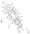
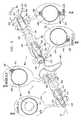
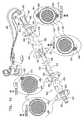
ここで、本発明の好ましい実施形態により構築され動作する、補助内視鏡アセンブリ(図7A〜8Pに示されている)のような、弾性拡張可能カラー部分を有する補助装置を内視鏡(図7J〜7L、7O〜7Qおよび8J〜8Pに示されている)に取り付ける装置100を示す図1〜6Fを参照する。 Here, an auxiliary device having an elastically expandable collar portion, such as an auxiliary endoscope assembly (shown in FIGS. 7A-8P), constructed and operative in accordance with a preferred embodiment of the present invention (FIG. Reference is made to FIGS. 1-6F showing the
用語「内視鏡」および「内視鏡検査」は、全体に亘って慣例的な意味よりやや広い意味で使用され、たとえば、小腸、大腸、動脈および静脈のような体腔、体内流路などで動作する装置および方法を指している。これらの用語は、通常は、目視検査を指すが、本明細書中で使用される場合には、これらの用語は目視検査を利用する用途に限定されることがなく、必ずしも目視検査を必要としない装置、システムおよび方法も指している。 The terms “endoscopy” and “endoscopy” are used in a slightly broader sense throughout the general sense, eg in body cavities such as the small intestine, large intestine, arteries and veins, body passages, etc. Refers to an apparatus and method that operates. These terms usually refer to visual inspection, but as used herein, these terms are not limited to applications that utilize visual inspection and do not necessarily require visual inspection. Also refers to devices, systems and methods that do not.
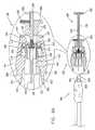
図1および2を概略的に参照すると、装置100は、好ましくは、縦軸104を中心にほぼ対称である手動係合可能要素102(図4A〜4E)のようなシャーシ要素を備えることがわかる。駆動用アセンブリ106(図3A〜3D)は、要素102に対して縦軸104に沿って手動で駆動するために設けられている。 Referring generally to FIGS. 1 and 2, it can be seen that the
4個のアーム要素108が、要素102の上に回動可能に設けられ、縦軸104を中心にほぼ対称に分布しており;これらの要素は、各々のピン110によって、要素112内に形成され、半径方向および軸方向に延びる各スロット112に、選択的・変位可能に入ったり、部分的に出たりできるようになっている。 Four
スプリング114が、それぞれのスロット112内に配置され、それぞれのアーム要素108を係合させてアーム要素108を半径方向外方へ付勢する。スプリング114は、好ましくは、それぞれのピン116に取り付けられ、各々のアーム要素108に形成されたそれぞれの切り抜き部118内に位置している。軸方向に駆動されるカラー係合要素120は、駆動用アセンブリ106の前方端に着脱自在に取り付けられている。回転防止ピン122は、軸104を中心として要素102に対してカラー係合要素120が回転するのを妨ぐために、駆動用アセンブリ106の軸方向延在スロット124と係合する。 A
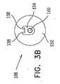
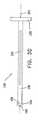
特に図3A〜3Dに見られるように、駆動用アセンブリ106は、好ましくは、軸方向延在スロット124が形成されているほぼ円筒状のロッド部分130を備える。ほぼ円筒状のロッド部分130の後方端には、好ましくは、円板のような手動係合部分132が設けられている。ほぼ円筒状のロッド部分130の前方端には、好ましくは、ほぼ平面状であり、縦軸104と垂直な平面に延在し、エッジ面138を有する切り抜き部136を有するクイック解除コネクタ部分134が形成されている。コネクタ部分134の内部に部分的に配置され、通常は軸104に沿ってコネクタ部分134の軸方向前方へ延在するのは、独国Futwangen、3 TribergerのELESA−GANTERから市販されているスプリング荷重式ボールアセンブリ製品GN−614.3−4−NIのようなスプリング荷重式ボール係合アセンブリ140である。 As seen particularly in FIGS. 3A-3D, the
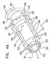
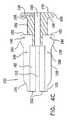
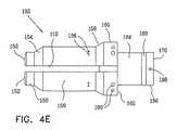
ここで、手動係合可能要素102を示す図4A〜4Eがさらに参照される。手動係合可能要素102は、好ましくは、前方向きのほぼ円形状のエッジ152を有するほぼ円筒状の前方部分150を含む、DELRIN(登録商標)またはステンレス鋼のような成形または機械加工された硬質プラスチックまたは金属で好ましくは形成されている一体形成されたほぼ円形状の対称本体を備える。前方部分150の後方には、好ましくは、後方に向かって増加する外径を有する前方のほぼ円錐状の移行部分154が設けられている。 Reference is now further made to FIGS. 4A-4E showing the manually
部分154の後方には、好ましくは、主円筒状部分156が形成され、その後方には後方に向かって増加する外径を有するほぼ円錐状の移行部分158が形成されている。部分158の後方には、好ましくは、後方に向くバルクヘッド面162を有する後方の円筒状部分160が形成されている。部分160の後方には、好ましくは、前方に向く翼面168および後方に向かく面170を有する翼状のほぼ平面状の端部分166で終端する比較的狭い円筒状部分164が形成されている。 Behind the
縦軸104に沿って手動係合可能要素102の部分166、164、160および部分158の一部を貫通して軸方向に延在するのは、ほぼ円筒状のロッド部130を摺動可能に収容し、円筒形状のロッド部130が手動係合可能要素102と相対的に軸方向変位する際に案内する比較的狭いほぼ円形状の円筒状ボア180である。 Axially extending along the
円筒状ボア180の前方には、手動係合可能要素102の部分158の一部と部分156、154および150とに、前方に向くほぼ円形状エッジ152の内径を画定する比較的広いほぼ円形状の円筒状ボア182が形成されている。 Forward of the
軸方向延在スロット112は、相互に隣接する90度の相対的な向きに延在しており、部分164内の、面162のわずかに後方の場所から前方へ、部分160、158、156、154および150を前方へ貫いていることがわかる。 The
ボア190が部分160に形成されて、それぞれのピン110を収容する。ボア196が主円筒状部分156に形成されてそれぞれのピン116を収容し、ボア198が部分166に形成されて、部分的にボア180内に延び、それによって駆動用アセンブリ106の軸方向延在スロット124と係合するピン122を収容する。 A
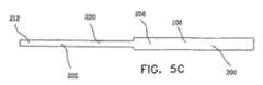
ここで、アーム要素108を示す図5A〜5Cをさらに参照する。特に図5A〜5Cに見られるように、各アーム要素108は、第1の比較的大きい厚さをもつ後方部分200と第2の比較的小さい厚さをもつ後方部分202とを含むほぼ平面状要素である。 Reference is now further made to FIGS. 5A-5C showing the
後方部分は、後方に配置されて、ピン110を収容する横方向に延在するボア204と、切り抜き部118とを含む。後方部分は、外向きエッジ面206と部分的に湾曲した内向きエッジ面208とを含む。 The rear portion includes a laterally extending
前方部分202は、カラー係合エッジ面212と、前方に配置された、内向きエッジ面214とを有する最も前方のフィンガー部分210を含み、内向きエッジ面214は、ショルダー部216まで後方に延在し、ショルダー部216の後方には、内向きエッジ面218がある。また、部分的に湾曲した外向きエッジ面220がカラー係合エッジ面212の後方まで延在している。 The
ここで、軸方向に駆動されるカラー係合要素120を示す図6A〜6Fを参照する。図6A〜6Fに見られるように、カラー係合要素120は、後方に配置されたハブ230を有するほぼ円筒状の対称要素であり、ハブ230の周囲に分散配置された4個のカラー係合ベーン232がハブ230から軸方向前方へ延在している。 Reference is now made to FIGS. 6A-6F showing the
ハブ230は、後方に向く壁部分234を画定し、壁部分234内にはほぼ円筒状のロッド部分130を収容する軸方向凹部236が形成されている。後方に向く壁部分234の前方には、クイック解除コネクタ部分134を収容し、かつ、後方に向く壁部分234を中間壁部分242の後方に向く面240から離す横方向スロット238が設けられている。中間壁部分242内には、スプリング荷重式ボール係合アセンブリ140を収容するために配置され構成されている凹部244が形成されている。クイック解除コネクタ部分134が横方向スロット238に挿入されるとき、切り抜き部136のエッジ面138は、中間壁部分242の対応するエッジ面246と一致するか、または、当該エッジ面246の半径方向内部に位置していることが好ましく、当該エッジ面246は、中間ベーン232に位置している中間壁部242の他の対応するエッジ面248と同じだけ軸104から半径方向に離れていることが好ましい。 The
好ましくは、弾性材料で作られたパッド250は、中間壁部分242の前方に向く面252に装着される。パッド250は、典型的に、内視鏡の前方端と係合し、衝撃破損からその前方端を保護するため設けられている。 Preferably, a
カラー係合ベーン(翼板)232は、好ましくは、ほぼ丸い前方に向くエッジ面260、ならびに、やや丸い外向きカラー係合面262およびやや丸い内向き内視鏡係合面264を有する。 The
本発明の好ましい実施形態によれば、ベーン232は、長さ約16.5mmと幅約6.5mmとを有し、パッド250の厚さは約1.5mmである。本発明のさらに好ましい実施形態によれば、対向するベーン232どうしの内向き内視鏡係合面264の間の距離は約14mmであるので、内視鏡を破損させることなく約13mmまでの直径を有する内視鏡を内視鏡係合面の間に挿入することが可能となる。 According to a preferred embodiment of the present invention, the
任意の適当な数のベーン232が利用されてもよいことが理解される。したがって、任意の適当な数のアーム要素108が利用されてもよいことが理解される。特に、3個のベーン232および3個のアーム要素108が利用されてもよい。 It will be appreciated that any suitable number of
ここで、補助内視鏡アセンブリを内視鏡に取り付ける図1および2の装置の動作における種々の段階、および、内視鏡に取り付けられた補助内視鏡アセンブリのカラーを切断するカラー切断ツールの動作における種々の段階の概略図である図7A、7B、7C、7D、7E、7F、7G、7H、7I、7J、7K、7L、7M、7N、7O、7Pおよび7Qが参照され、対応する図7A〜7Pにおける図1および7A〜7Pにおける線VIII−VIIIの断面図である図8A、8B、8C、8D、8E、8F、8G、8H、8I、8J、8K、8L、8M、8N、8Oおよび8Pが参照される。 Here, various stages in the operation of the apparatus of FIGS. 1 and 2 for attaching the auxiliary endoscope assembly to the endoscope, and of a color cutting tool for cutting the collar of the auxiliary endoscope assembly attached to the endoscope. Reference is made to FIGS. 7A, 7B, 7C, 7D, 7E, 7F, 7G, 7H, 7I, 7J, 7K, 7L, 7M, 7N, 70, 7P and 7Q, which are schematic diagrams of the various stages of operation. 8A, 8B, 8C, 8D, 8E, 8F, 8G, 8H, 8I, 8J, 8K, 8L, 8M, 8N, which are cross-sectional views of line VIII-VIII in FIGS. 1A and 7A-7P in FIGS. Reference is made to 8O and 8P.
図7A〜8Pに見られるように、装置100は、補助内視鏡アセンブリ300(図7A〜8Pに示されている)を内視鏡302(図7J〜7L、7O〜7Q、および8J〜8Pに示されている)取り付けるため使用される。内視鏡302は、いずれも独国、22527 ハンブルグ、104 Julius−Vosseler St.所在のPentax Europe GmbHから市販されている、EPK−1000ビデオプロセッサおよびSONY LMD−2140MD医療用フラット・パネルLCDモニタを含むコンソールのような内視鏡コンソールに接続可能である、好ましくは、VSB−3430Kビデオ小腸内視鏡またはEC−3470LKビデオ大腸内視鏡のような従来の内視鏡である。 As seen in FIGS. 7A-8P,
図示された実施例では、補助内視鏡アセンブリは、NaviAid BGEというモデル名でイスラエル RaananaのSmart所在のMedical Systems Ltd.から市販され、開示内容が参照によって本明細書に組み込まれている公開されたPCT出願PCT/IL2005/000849、PCT/IL2007/000600およびPCT/IL2007/000832に記載されている。装置100は、代替的に、弾性カラー304を有する別のタイプのアセンブリを内視鏡または別の細長い要素に取り付けるために利用されてもよいことが認識される。弾性カラー304は軸方向外向き周辺エッジ306を有している。 In the illustrated embodiment, the auxiliary endoscope assembly is modeled as NaviAid BGE, Medical Systems Ltd. of Smartan, Raana, Israel. Published PCT applications PCT / IL2005 / 000849, PCT / IL2007 / 000600 and PCT / IL2007 / 000832, the disclosure of which is incorporated herein by reference. It will be appreciated that the
好ましくは、カラー304は、ラテックスまたは伸張可能シリコンのような弾性の比較的伸張可能な材料で作られている。好ましくは、弛緩状態にあるカラー304の寸法は6〜20mmの範囲にあり、内径は6〜10mmの範囲にあり、厚さは1〜2mmの範囲にある。本発明の好ましい実施形態によれば、カラー304は、長さ約10mmと、内径約8mmと、外径約11mmとを有している。 Preferably, the
好ましくは、カラー304は、様々な径をもつ内視鏡へ緊密かつ固定的に取り付けられるよう構成されている。たとえば、弛緩状態において長さ10mm、内径8mmおよび外径11mmを有し、最大伸張状態において内径23mmを有するカラー304は、9.8〜13mmの範囲にある径を有する内視鏡への緊密かつ固定した取り付けに適している。 Preferably, the
図7Aおよび8Aは、相互係合前の装置100および補助内視鏡アセンブリ300を示している。カラー係合要素120はクイック解除コネクタ部分134によって係合される。この係合は、スプリング荷重式ボール係合アセンブリ140が凹部244・BR>ニ係合することによって少なくとも部分的に維持される。 FIGS. 7A and 8A show the
図7Bおよび8Bは、カラー304が装置100と対向した状態で、一方の手で装置100を保持し、他方の手で補助内視鏡アセンブリ300を保持するユーザを示している。この段階で、駆動用アセンブリ106は、手動係合可能要素102に対して完全に引き込められていることに留意する。この段階で、ユーザの手は、アーム要素108の外向きエッジ面206および220にかけられて、アーム要素108のカラー係合エッジ面212がほぼ先端が切り取られていない錐体を画定し、それによって、図7Cおよび8Cに見られるようにカラー304内に挿入され、カラー304を部分的に伸張させることができるように可能な限り最大に、スプリング114による付勢に対抗して、アーム要素108の外向きエッジ面206および220を半径方向内向きに押すことにも留意する。 FIGS. 7B and 8B illustrate a user holding the
図7Dおよび8Dは、ユーザの手がそれ以上アーム要素108を内向きに押さないとき、カラー304を部分的に伸張させるカラー係合エッジ面212を示している。通常、スプリング114は、同一である図8Cおよび8Dの比較からわかるように、カラー304のさらなる伸張がこの段階で起こらないように選択される。 FIGS. 7D and 8D show a collar engaging
図7Eおよび8Eは、手動係合可能要素102に対する、駆動用アセンブリ106の僅かな前方軸方向変位を示している。この前方変位は、カラー係合要素120のハブ230のエッジ面246および248と、対応する内向きエッジ面208との間の係合が強制的にアーム要素108を要素102におけるボア190内でピン110を中心に半径方向外向きに回動させるようにカラー係合要素120を軸方向前方へ移動させ、それによって、フィンガー部分210のカラー係合エッジ面212によって画定される錐体をさらに拡張し、カラー304をさらに伸張させる。 FIGS. 7E and 8E show a slight forward axial displacement of the
図7Fおよび8Fは、手動係合可能要素102に対する、駆動用アセンブリ106のさらなる前方軸方向変位を示している。この付加的な前方向変位は、カラー係合要素120をカラー係合要素120のハブ230のエッジ面246および248と、対応する内向きエッジ面218との間の係合が強制的にアーム要素108を手動係合可能要素102におけるボア190内でピン110を中心に半径方向にさらに外向きに回動させるように、さらに軸方向前方へ移動させ、それによって、フィンガー部分210のカラー係合エッジ面212によって画定される錐体をさらに拡張させ、またカラー304をさらに伸張させる。このさらなる前方向変位によって、ベーン232の前方部分がカラー304の内部に接触係合なしに配置される。 FIGS. 7F and 8F illustrate further forward axial displacement of the
図7Gおよび8Gは、手動係合可能要素102に対する、駆動用アセンブリ106のさらなる前方軸方向変位を示している。この、さらなる前方変位は、カラー係合要素120をカラー係合要素120のハブ230のエッジ面246および248と、ショルダー部216によって内向きエッジ面218から離されて面218に対して半径方向外向きに位置している対応する内向きエッジ面214との間の係合が、カラー係合エッジ面212と係合するカラー要素304によって付勢されている状態で、アーム要素108を手動係合可能要素102におけるボア190内でピン110を中心に半径方向内向きに回動させるように、さらに軸方向前方へ移動させる。これは、ベーン232の外向きカラー係合面262とカラー304の内部との接触および支持係合だけによって、カラー304が伸張することを可能にするフィンガー部分210のカラー係合エッジ面212によって画定された、先端が切り取られた錐体を収縮させる。 FIGS. 7G and 8G illustrate further forward axial displacement of the
図7Hおよび8Hは、手動係合可能要素102に対する、駆動用アセンブリ106の最大前方軸方向変位を示している。この最大前方変位は、アーム要素108のフィンガー部分210がカラー304ともはや接触係合せず、カラー304から引き込まれるように、ピン122と、ほぼ円筒状のロッド部分130におけるスロット124の後方端との係合によって制限される最大にカラー係合要素120を軸方向前方へ移動させ、それによって、アーム要素108が、スプリング114によって付勢されている状態で、手動係合可能要素102におけるボア190内でピン110を中心に半径方向外向きに回動することを可能にする。 FIGS. 7H and 8H show the maximum forward axial displacement of the
図7Iおよび8Iは、カラー係合要素120のベーン232との係合、および、円筒状ロッド部分130からのカラー係合要素120の係合解除とにより伸張しているカラー304を示している。 FIGS. 7I and 8I show the
図7Jおよび8Jは、カラー304はカラー係合要素120のベーン232との係合によって依然として伸張している状態における、カラー304が配置されている端とは反対側にある補助内視鏡アセンブリ300の端322からの補助内視鏡アセンブリ300のルーメン320内への内視鏡302の初期的な挿入を示している。 FIGS. 7J and 8J show that the
図7Kおよび8Kは、内視鏡302の前方端324がカラー係合要素120に接しているパッド250と係合するような、補助内視鏡アセンブリ300のルーメン320内への内視鏡302の完全な挿入を示している。 FIGS. 7K and 8K show the
図7Lおよび8Lは、カラー係合要素120のスロット238内にクイック解除コネクタ部分134を挿入することによるカラー係合要素120と円筒状ロッド部分130との再係合を示している。この係合は、スプリング荷重式ボール係合アセンブリ140と凹部244との係合によって少なくとも部分的に維持される。この段階で、駆動用アセンブリ106は、好ましくは、完全に前方位置にある。 FIGS. 7L and 8L illustrate the re-engagement of the
ここで、カラー係合要素120から弾性アウター管状カラー304を少なくとも一部分係合解除するために動作する弾性アウター管状物体係合解除機能を図示する図7M、7N、8Mおよび8Nを特に参照する。 Reference is now made in particular to FIGS. 7M, 7N, 8M and 8N which illustrate the elastic outer tubular object disengagement function which operates to at least partially disengage the elastic outer
図7Mおよび8Mは、前方向きのほぼ円形状のエッジ152がカラー304の軸方向外向きエッジ306と接触係合する段階までの手動係合可能要素102に対する、駆動用アセンブリ106の初期の引き込み動作を示している。 FIGS. 7M and 8M show the initial retracting motion of the
図7Nおよび8Nは、カラー係合要素120のベーン232がカラー304の内部から引き込まれ、そして、係合解除される段階までの手動係合可能要素102に対する、駆動用アセンブリ106の完全な引き込み動作を示している。この段階で、弾性カラー304は、内視鏡302の端部324をキョ個に FIGS. 7N and 8N show a full retraction operation of the
前述された装置100の構造および方法は、内視鏡302の端324をカラー304の軸方向外向きエッジ306から、好ましくはベーン232の長さに依存する所定の距離に位置付けることが認識される。本発明の好ましい実施形態によれば、ベーン232は、約16.5mmの長さおよび約6.5mmの幅を有し、パッド250の厚さは約1.5mmであるので、約10mmの長さを有する弾性カラー304を内視鏡302の前方エッジから約2〜5mmの距離に配置する。 It will be appreciated that the structure and method of the
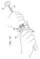
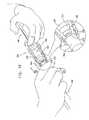
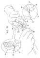
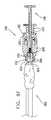
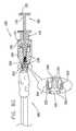
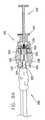
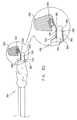
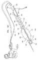
図7Oおよび8Oは、補助内視鏡アセンブリ300を内視鏡302から係合解除する初期ステップを示している。好ましくは、細長いテーパー付き前方フィンガー部332およびカラー切断エッジ334を有するカラー切断ツール330がこの目的のため利用される。前方フィンガー部332は、好ましくは、前方フィンガー部332の前方部分336で最大の柔軟性を示し、前方部分から後方へ徐々に剛性が増大する。前方フィンガー部332は、好ましくは、硬度が内視鏡302の外面の硬度より低い材料で作られ、それによって内視鏡320へのあらゆる損傷を防止する。図7Oおよび8Oは、前方フィンガー部332がスペーサとしての役目を果たし、カラー304および切断エッジ334から内視鏡302を隔てるような、カラー304と内視鏡302との間の前方フィンガー部332の前方部分336の挿入を示している。 FIGS. 7O and 8O show the initial steps of disengaging the
図7Pおよび8Pは、補助内視鏡アセンブリ300を内視鏡302から係合解除するさらなるステップを示している。カラー切断ツール330のカラー切断エッジ334はカラー304の外向きエッジ306と係合し、エッジ306に切れ目340を形成する。 7P and 8P show a further step of disengaging the
図7Qは、切り目340におけるカラー304の完全なスリット化を示し、したがって、前述のカラー304と顕微鏡302との締め付け係合(図7N)はない。この段階で、補助内視鏡アセンブリ300は内視鏡302から簡単に外れることがある。 FIG. 7Q shows complete slitting of the
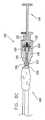
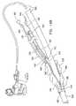
ここで、本発明の好ましい実施形態により構築され動作し、従来の内視鏡に取り付けるのに適したダブルバルーン装置400の概略部分切り欠き絵図である図9が参照される。図9に見られるように、ダブルバルーン装置は、柔軟性前方バルーン膨脹/収縮管406によって相互接続された前方内視鏡取り付け可能膨脹式バルーンアセンブリ402と後方内視鏡取り付け可能膨脹式バルーンアセンブリ404とを備える。 Reference is now made to FIG. 9, which is a schematic partial cutaway illustration of a
前方内視鏡取り付け可能膨脹式バルーンアセンブリ402は、好ましくは一体的に形成された前方向きの弾性カラー410を有し、好ましくは一般に柔軟性があり、好ましくは弾性の管状スリーブ408を含む。カラー410は、前述されたカラー304と類似していてもよいし、あるいは、スリーブ408からは別体とされて接着剤によってスリーブ408に装着されてもよい。別々に形成されるカラー410およびスリーブ408は、異なる材料で作られてもよいし、または、類似しているが、強度、柔軟性、伸張性、および、寸法のような異なる特性をもつ材料から作られてもよいことが認識される。たとえば、スリーブ408は、高い柔軟性および伸張可能性をもつシリコン材料で作られてもよいし、カラー410は、柔軟性および伸張可能性が低く、より高い耐拡張性を有するシリコン材料で作られてもよい。 The front endoscope attachable
スリーブ408は、好ましくは、円筒状であり、軸412の周りに配置され、好ましくは、内視鏡を収容するメインルーメン414と、柔軟性前方バルーン膨脹/収縮管406の前方部分418を収容するサイドルーメン416とを有している。サイドルーメン416は、後方向きの端部から前方へ、かつ軸412に対してほぼ螺旋状の経路に沿ってメインルーメン414の外向きに、スリーブ408の長さの一部に沿って延在し、開放端420で終端する。好ましくは、前方部分418は部分的に、サイドルーメン416に沿ってサイドルーメン416の内部に延在し、密封式膨脹/収縮通路をサイドルーメン416に設けるように、たとえば、適当な接着剤を用いてサイドルーメン416に固定密封式に装着されている。典型的に、スリーブ408は約8〜15cmの長さを有している。
スリーブ408は、柔軟性かつ伸張可能性のあるシリコン、ラテックス、または、ゴムのような柔軟性かつ伸張可能性のある材料で構成されてもよく、それによってスリーブ408はスリーブ408が取り付けられている内視鏡の撓みに適合できることが認識される。スリーブ408のメインルーメン414は、好ましくは中に挿入される内視鏡の断面周囲より僅かに大きく、張力がかからない内周を有し、それによって、内視鏡を取り付ける際に引かれて内視鏡上を滑ることができることがさらに認識される。 The
前方膨脹式バルーン430は、スリーブ408の外面に密封式に取り付けられ、前方膨脹式バルーン430を膨脹および収縮させるためサイドルーメン416の開放端420が前方膨脹式バルーン430の内部に位置するようにサイドルーメン416に対して配置されている。 The front
本発明の好ましい実施形態によれば、バルーン430は一般に膨脹式であり、膨脹していないときの径の約3〜10倍の径まで膨脹可能であることが認識される。本発明の好ましい実施形態によれば、小腸内視鏡に有用であるには、完全に膨脹したときのバルーン430の径は35〜45mmの範囲である。好ましくは、45mm未満の径までのバルーン430の膨脹は、たとえば20〜40ミリバールの範囲の比較的低い圧力を使用して達成されることがある。 In accordance with a preferred embodiment of the present invention, it will be appreciated that the
別の特定の実施形態では、大腸内視鏡に有用であるには、完全に膨脹したときのバルーン430の径は、4〜6センチメートルの範囲である。さらなる実施形態では、大腸内視鏡のためさらに有用であるには、完全に膨脹したときのバルーン430の径は6センチメートルである。好ましくは、6センチメートル未満の径までのバルーン430の膨脹は、たとえば20〜40ミリバールの範囲の比較的低い圧力を使用して達成されることがある。 In another specific embodiment, useful for a colonoscope, the diameter of
本発明の好ましい実施形態によれば、可変断面径を有するほぼ管状の人体部分の生体内検査に有用であるには、内視鏡に取り付けられたときのバルーン430の拡張径範囲は、ほぼ管状の人体部分の最大断面径より大きいので、拡張したバルーン430とほぼ管状の人体部分の内面との係合を可能にし、ほぼ管状の人体部分の内面への内視鏡のアンカー固定を可能にすることが認識される。好ましくは、バルーン430は、比較的柔らかく、高い適合性のあるバルーンであり、ほぼ管状の人体部分の内面と係合したとき、ほぼ管状の人体部分の内面の形状に少なくとも部分的に適合するように動作する。 According to a preferred embodiment of the present invention, the expanded diameter range of the
バルーン430は、ラテックス、柔軟性シリコン、または、高柔軟性ナイロンのような適当な周知の伸張可能な材料で作られてもよいことが認識される。あるいは、バルーン430は、ラテックス、柔軟性シリコン、または、高柔軟性ナイロンより伸張可能性および適合性の低いポリウレタンで作られてもよい。好ましくは、バルーン430の径は、ほぼ管状の人体部分のあらゆる部分で緊密なアンカー固定を確実にするのに十分である。あるいは、バルーン430は省略してもよい。 It will be appreciated that the
後方内視鏡取り付け可能膨脹式バルーンアセンブリ404は、好ましくは、ほぼ軸方向に圧縮不可能な管状スリーブ438を含む。スリーブ438は、好ましくは、円筒形であり、使用時に軸412の周りに配置され、好ましくは、内視鏡を収容するメインルーメン440と、第1のサイドルーメン442および第2のサイドルーメン444とを有している。 The posterior endoscope attachable
第1のサイドルーメン442は、柔軟性前方バルーン膨脹/収縮管406の後方部分446を収容する。第1のサイドルーメン442は、軸412に対してほぼ螺旋状経路に沿ってメインルーメン440の外向きに、スリーブ438の長さに沿って延在する。好ましくは、後方部分446は部分的に、第1のサイドルーメン442の前方向き部分448に沿って前方向き部分448の内側に延在し、たとえば、適当な接着剤によって、前方向き部分448に固定密封式に装着されて、密封式膨脹/収縮通路を前方向き部分448に設けている。前方向バルーン膨脹/収縮給排管450は部分的に、第1のサイドルーメン442の後方向き部分454に沿って後方向き部分の内側に、アセンブリ404の外側のコネクタ452から延在し、たとえば、適当な接着剤によって後方向き部分に固定密封式に装着されて、密封式膨脹/収縮通路を後方向き部分に設けている。 The
第2のサイドルーメン444は、柔軟性後方バルーン膨脹/収縮給排管464の前方部分462を収容する。第2のサイドルーメン444は、スリーブ438の後方エッジから開放端466へ軸412に対してほぼ螺旋状経路に沿ってメインルーメン440の外向きに、スリーブ438の長さの一部に沿って延在する。後方バルーン膨脹/収縮給排管464は部分的に、第2のサイドルーメン444の後方向き部分474に沿って後方向き部分474の内側に、アセンブリ404の外側のコネクタ472から延在し、たとえば、適当な接着剤によって後ろ向き部分に固定密封式に装着されて、後ろ向き部分に密封式膨脹/収縮通路を設けている。 The
後方膨脹可能バルーン480は、スリーブ438の外面に密封式に取り付けられ、第2のサイドルーメン444の開放端466が後方膨脹可能バルーンの膨脹および収縮を行うため後方膨脹可能バルーンの内部に位置するように、第2のサイドルーメン444に対して配置されている。本発明の好ましい実施形態によれば、バルーン480は一般的に膨脹式であり、膨脹していないときのバルーンの径より3〜10倍大きい径まで膨脹可能であることが認識される。本発明の好ましい実施形態によれば、小腸内視鏡に有用であるには、完全に膨脹したときのバルーン480の径は35〜45mmの範囲である。好ましくは、45mm未満の径までのバルーン480の膨脹は、たとえば20〜40ミリバールの範囲の比較的低い圧力を使用して達成されることがある。 The rear
別の特定の実施形態では、大腸内視鏡に有用であるには、完全に膨脹したときのバルーン480の径は、4〜6センチメートルの範囲である。さらなる実施形態では、大腸内視鏡のためさらに有用であるには、完全に膨脹したときのバルーン480の径は6センチメートルである。好ましくは、6センチメートル未満の径までのバルーン480の膨脹は、たとえば20〜40ミリバールの範囲の比較的低い圧力を使用して達成されることがある。 In another specific embodiment, useful for large intestine endoscopes, the diameter of
本発明の好ましい実施形態によれば、可変断面径を有するほぼ管状の人体部分の生体内検査に有用であるには、スリーブ438に取り付けられたときのバルーン480の拡張径範囲は、ほぼ管状の人体部分の最大断面径より大きいので、拡張したバルーン480とほぼ管状の人体部分の内面との係合を可能にし、ほぼ管状の人体部分の内面へのスリーブ438のアンカー固定を可能にすることが認識される。好ましくは、バルーン480は、比較的柔らかく、高い適合性のあるバルーンであり、ほぼ管状の人体部分の内面と係合したとき、ほぼ管状の人体部分の内面の形状に少なくとも部分的に適合するように動作する。 In accordance with a preferred embodiment of the present invention, in order to be useful for in vivo examination of a generally tubular human body portion having a variable cross-sectional diameter, the expanded diameter range of the
バルーン480は、ラテックス、柔軟性シリコン、または、高柔軟性ナイロンのような適当な周知の伸張可能な材料で作られてもよいことが認識される。あるいは、バルーン480は、ラテックス、柔軟性シリコン、または、高柔軟性ナイロンより伸張可能性および適合性の低いポリウレタンで作られてもよい。好ましくは、バルーン480の径は、ほぼ管状の人体部分のあらゆる部分で緊密なアンカー固定を確実にするのに十分である。あるいは、バルーン480は省略してもよい。 It will be appreciated that the
好ましくは、オペレータが軸412を中心とする管438の望ましくない回転を監視し阻止することを可能にさせるため基準マーク482がスリーブ438の後方端に設けられる。好ましくは、スリーブ438は、約120〜150cmの典型的な長さからなり、内径約10〜13.5mmおよび外径約12〜15.5mmを有して、従来の内視鏡上を容易に摺動可能としている。好ましくは、スリーブ438は、たとえば9.5〜13mmの範囲の種々の径の内視鏡に取り付けるように構成されている。 Preferably, a
スリーブ438は比較的柔軟性があり、それによってスリーブ438が摺動可能に取り付けられる内視鏡の撓みに適合でき、かつ、十分に剛性もあり、それによってスリーブの後方端でスリーブを前方へ押すことによるスリーブの内視鏡上の摺動を可能にすることが認識される。 The
スリーブ438は、シリコン、PEBAX(登録商標)、PVCまたはポリウレタンのような適当な材料で作られてもよい。本発明の好ましい実施形態によれば、スリーブ438の内面は、湾曲姿勢の内視鏡上のスリーブ438の低抵抗摺動を可能にするように、薄く、柔軟性のある内部TEFLON(登録商標)管または親水性コーティングのような低摩擦材料で作られる。 The
ここで、従来の内視鏡システムの一部を形成する従来の内視鏡に取り付けられた図9のダブルバルーン装置の概略絵図である図10が参照される。内視鏡490は前述された内視鏡302と同一でもよい。 Reference is now made to FIG. 10, which is a schematic pictorial illustration of the double balloon device of FIG. 9 attached to a conventional endoscope that forms part of a conventional endoscope system. The
実際には、最初に後方内視鏡取り付け可能膨脹式バルーンアセンブリ404は、従来のオーバーチューブの方法で内視鏡490の前方端492上を摺動させられる。その後、前方内視鏡取り付け可能膨脹式バルーンアセンブリ402は、好ましくは、図1〜7Nおよび8A〜8Nを参照して前述された装置100を使用して、内視鏡490の前方端492に隣接してぴったり取り付けられたカラー410を用いて内視鏡にぴったり合わされている。 In practice, the posterior endoscope attachable
ダブルバルーン装置400の動作は、米国ニュージャージー州Wayne、10 High Point Drive所在のFujinon Inc.からすべて市販されているバルーン・ポンプ・コントロールBP−20および2200ビデオシステムとインターフェイスをとるEN−450T5小腸内視鏡、TS−13140オーバーチューブおよびBS−2フロントバルーンを含むダブルバルーン内視鏡アセンブリのような市販されているダブルバルーン内視鏡の動作と同一または類似していてもよい。 The operation of the
使用後の内視鏡490からのダブルバルーン装置400の係合解除は、図7O〜7Qおよび8O〜8Pを参照して前述されたカラー切断ツール330を使用して容易に実現されることがある。 Disengagement of the
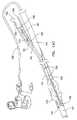
ここで、本発明の好ましい実施形態により構築され動作する内視鏡オーバーチューブの開姿勢および閉姿勢のそれぞれにおける概略絵図である図11Aおよび11Bと、図11Aおよび11Bの内視鏡オーバーチューブの概略分解絵図である図12と、それぞれ図11A〜12の内視鏡オーバーチューブで利用されるバルーンの概略絵図、概略端面図および概略側面図である図13A、13Bおよび13Cとが参照される。 Here, FIGS. 11A and 11B which are schematic pictorial views in the open posture and the closed posture of the endoscope overtube constructed and operated according to the preferred embodiment of the present invention, and the outline of the endoscope overtube of FIGS. 11A and 11B, respectively. Reference is made to FIG. 12, which is an exploded view, and to FIGS. 13A, 13B and 13C, which are schematic pictorial, schematic end and schematic side views of the balloon utilized in the endoscope overtube of FIGS.
図11A〜12に見られるように、本発明の好ましい実施形態により構築され動作し、縦軸504の周りに配置されたほぼ軸方向に圧縮不可能な管状のほぼ円筒状のスリーブ502を含む内視鏡オーバーチューブ500が設けられている。スリーブ502には、好ましくは、参照符号506によって示されている軸方向のスリットが形成されて、軸方向スリットエッジ508および510を画定し、それによって、円周方向に拡張可能および圧縮可能である。選択的に膨脹可能/収縮可能なバルーン520が、スリーブ502の外面522の一部に取り付けられている。 As seen in FIGS. 11A-12, an internal construction comprising and operating in accordance with a preferred embodiment of the present invention includes a substantially axially incompressible tubular generally
スリーブ502は、好ましくは、前述された内視鏡302に類似していることがある内視鏡530を収容するメインルーメン528と、スリーブ502の外面522に沿って互いに円周方向に隔てられている第1のサイドルーメン532および第2のサイドルーメン534とを有している。 The
第1のサイドルーメン532は、柔軟性バルーン膨脹/収縮管540の前方部分536を収容し、メインルーメン528の外向きに、バルーン520の内部の下に位置しバルーン520の内部と流体連通している開口542までスリーブ502の長さに沿って部分的に延在する。好ましくは、柔軟性管540はスリーブ502の外側のコネクタ544から延在し、柔軟性管の前方部分536は部分的に、第1のサイドルーメン532の後方向き部分546に沿って、後方向き部分の内側に延在し、適当な接着剤などによって後方向き部分に固定密封式に装着されて、密封式膨脹/収縮通路を後方向き部分に設けている。 The
第2のサイドルーメン534は、スリーブ502の外側のツール挿入ポート552から延在する柔軟性器具チャネル550の前方部分548を収容する。第2のサイドルーメン534は、スリーブ502の全長に沿って、バルーン520の下にあるスリーブ502の外面522に沿って、スリーブ502の後方エッジから開放端554まで延在する。器具チャネル550は部分的に、第2のサイドルーメン534の後方向き部分556に沿って後方向き部分556の内側に、ポート552から延在し、適当な接着剤などによって後方向き部分に固定的に装着されている。 The
バルーン520は、好ましくは、スリーブ502に組み合わされ、内視鏡530(図11B)に確実に取り付けられたとき、ほぼ円筒状の構造を有する予め形成された柔軟性要素である。バルーン520は、好ましくはスリーブ502の外面522に接着結合、または、加熱溶接された周辺密封面を含む。周辺密封面は、好ましくは、前方円周カラー密封面560および後方円周カラー密封面562と、スリットエッジ508および510と平行に延在する第1の軸方向密封面564および第2の軸方向密封面566とを含む。
スリーブ502のほぼ軸方向スリット506は、縦軸504に平行な直線状スリット、縦軸504に沿った螺旋状スリット、または、正弦波状スリットなど直線状でも曲線状でもよいことが認識される。スリーブ502の前方エッジは、好ましくは、腸などのほぼ管状の人体部分の生体内検査中に検査対称の組織を損傷させないように、滑らかであり、かつ、丸みを帯びている。 It will be appreciated that the generally
好ましくは、スリーブ502は、約100〜160cmの典型的な長さからなり、内径約10〜13.5mmおよび外径約12〜15.5mmを有して、従来の内視鏡上を容易に摺動可能としている。好ましくは、スリーブ502は、たとえば9.5〜13mmの範囲の種々の径の内視鏡に取り付けるよう構成されている。さらに好ましくは、スリーブ502の厚さは0.3〜2mmの範囲であって、一定でもよいし、長さに沿って変化してもよい。 Preferably, the
本発明の好ましい実施形態によれば、バルーン520の下にあるスリーブ502の前方部分は比較的剛性があるので、バルーン520の膨脹中にスリーブ502の内向き拡張を許容せず、それによって、バルーン520が膨脹したときにスリーブ502内を通る内視鏡530の摺動運動が可能となる。あるいは、バルーン520の下にあるスリーブ502の前方部分は高柔軟性があるので、バルーン520の膨脹中にスリーブ502の内向き拡張を許容し、それによって、バルーン520が膨脹したときに内視鏡530と係合してスリーブ502に対する内視鏡の位置を固定し、それによって、スリーブと内視鏡との間の摺動運動を阻止する。 According to a preferred embodiment of the present invention, the forward portion of the
スリーブ502は比較的柔軟性があり、それによってスリーブが摺動可能に取り付けられている内視鏡530の撓みに適合でき、かつ、十分に剛性もあり、それによってスリーブの後方端でスリーブを前方へ押すことによるスリーブの内視鏡530上の摺動を可能にすることが認識される。スリーブ502は、シリコン、PEBAX(登録商標)、PVCまたはポリウレタンのような適当な材料で作られてもよい。本発明の好ましい実施形態によれば、スリーブ502の内面は、湾曲姿勢の内視鏡上のスリーブ502の低抵抗摺動を可能にするように、薄く、柔軟性のある内部TEFLON(登録商標)管または親水性コーティングのような低摩擦材料で作られる。 The
本発明の好ましい実施形態によれば、バルーン520は一般に膨脹式であり、膨脹していないときの径の約3〜10倍の径まで膨脹可能であることが認識される。本発明の好ましい実施形態によれば、小腸内視鏡に有用であるには、完全に膨脹したときのバルーン520の径は35〜45mmの範囲である。好ましくは、45mm未満の径までのバルーン520の膨脹は、たとえば20〜40ミリバールの範囲の比較的低い圧力を使用して達成されることがある。 In accordance with a preferred embodiment of the present invention, it will be appreciated that the
別の特定の実施形態では、大腸内視鏡に有用であるには、完全に膨脹したときのバルーン520の径は、4〜6センチメートルの範囲である。さらなる実施形態では、大腸内視鏡のためさらに有用であるには、完全に膨脹したときのバルーン520の径は6センチメートルである。好ましくは、6センチメートル未満の径までのバルーン520の膨脹は、たとえば20〜40ミリバールの範囲の比較的低い圧力を使用して達成されることがある。 In another specific embodiment, useful for a colonoscope, the diameter of the
本発明の好ましい実施形態によれば、可変断面径を有するほぼ管状の人体部分の生体内検査に有用であるには、スリーブ502に取り付けられたときのバルーン520の拡張径範囲は、ほぼ管状の人体部分の最大断面径より大きいので、拡張したバルーン520とほぼ管状の人体部分の内面との係合を可能にし、ほぼ管状の人体部分の内面へのスリーブ502のアンカー固定を可能にすることが認識される。好ましくは、バルーン520は、比較的柔らかく、高い適合性のあるバルーンであり、ほぼ管状の人体部分の内面と係合したとき、ほぼ管状の人体部分の内面の形状に少なくとも部分的に適合するように動作する。 In accordance with a preferred embodiment of the present invention, in order to be useful for in vivo examination of a generally tubular human body portion having a variable cross-sectional diameter, the expanded diameter range of the
バルーン520は、ラテックス、柔軟性シリコン、または、高柔軟性ナイロンのような適当な周知の伸張可能な材料で作られてもよいことが認識される。あるいは、バルーン520は、ラテックス、柔軟性シリコン、または、高柔軟性ナイロンより伸張可能性および適合性の低いポリウレタンで作られてもよい。好ましくは、バルーン520の径は、ほぼ管状の人体部分のあらゆる部分で緊密なアンカー固定を確実にするのに十分である。あるいは、バルーン520は省略してもよい。複数のラッチ570がオーバーチューブ500を内視鏡530に選択的に確実に取り付けるため設けられ、バルーン520の下にはないオーバーチューブ500の長さに沿って分散配置されている。これらのラッチの各々は、好ましくは、接着剤または加熱溶接によって一方の端部574でスリット506のエッジ508および510の一方に隣接するスリーブ502の外面522に接合させられるアーム部分572を含む。各アームの反対側の端部576には、エッジ508および510の他方に隣接して取り付けられた対応する第2の装着部分580と着脱自在に係合する第1の装着部分578が設けられている。図示された実施形態では、アーム部分572は、隣接するエッジ508に装着され、第1の装着部分578は、第2の装着部分580を画定する対応する突起部と嵌合する凹部である。任意の他の適当な配置が利用されてもよい。 It will be appreciated that the
ここで、図11A〜12の内視鏡オーバーチューブと従来の内視鏡および従来の内視鏡ツールとの関連性の概略図である図14A、14B、14C、14Dおよび14Eが参照される。 Reference is now made to FIGS. 14A, 14B, 14C, 14D, and 14E, which are schematic views of the relationship between the endoscope overtubes of FIGS. 11A-12 and conventional endoscopes and conventional endoscope tools.
図14Aは、従来の内視鏡システムの一部を形成する内視鏡530に取り付けられようとしている図11A〜12のオーバーチューブ500を示している。内視鏡システムは、たとえば、いずれも独国、22527 ハンブルグ、104 Julius−Vosseler St.所在のPentax Europe GmbHから市販されている、EPK−1000ビデオプロセッサおよびSONY LMD−2140MD医療用フラット・パネルLCDモニタを含むコンソールのような内視鏡コンソールに接続可能である、VSB−3430Kビデオ小腸内視鏡またはEC−3470LKビデオ大腸内視鏡のような従来の内視鏡を備えてもよい。オーバーチューブ500の前方部は、スリット506が内視鏡530の厚さを収容可能であるように拡張された開姿勢にあることがわかる。 FIG. 14A shows the
図14Bは、バルーン520の一部を含み、内視鏡530と確実な係合状態にラッチされたオーバーチューブ500の最も前方部を示している。図14Cは、バルーン520を含み、内視鏡530と確実な係合状態にラッチされたオーバーチューブ500をさらに示している。図14Dは、内視鏡530と確実な係合状態にラッチされたオーバーチューブ500の全部を示している。図14Eは、膨脹したときのバルーン520の一般的な構成と、ポート552と、管500と、好ましくは、柔軟性内部TEFLON(登録商標)管、親水性コーティング、または、任意の代替的な適当な低摩擦ルーメンを備える低摩擦ルーメンである第2のサイドルーメン534とによって画定された、器具チャネルを通る従来の内視鏡ツールの挿入とを示している。 FIG. 14B shows the foremost portion of the
当業者によって認識されるように、本発明は、具体的に図示され、本明細書中に前述された事項によって限定されない。それどころか、本発明の範囲は、前述された種々の特徴の組み合わせおよび部分的な組み合わせの両方だけでなく、本明細書を読んだ当業者が想到する変形および変更であって、従来技術に含まれないものを含む。 As will be appreciated by those skilled in the art, the present invention is not limited by what has been particularly shown and described hereinabove. On the contrary, the scope of the present invention includes not only both the combinations and partial combinations of the various features described above, but also variations and modifications that will occur to those skilled in the art who have read this specification and are included in the prior art. Including no.
Claims (5)
Translated fromJapanese手持ち式カラー切断ツール本体部分と、
前記切断ツール本体部分と関連付けられ、前記弾性カラー部分を切断するようになっている切断エッジと、
前記手持ち式カラー切断ツール本体部分から突出し、前記弾性カラー部分からおよび前記切断エッジから前記内視鏡を隔てるために、前記弾性カラー部分と前記内視鏡との間に挿入されるようになっているスペーサ部分と、
を含む手持ち式カラー切断ツール。A handheld color cutting tool for removing an auxiliary endoscope assembly having an elastic collar portion from an endoscope, comprising:
Hand-held color cutting tool body part,
A cutting edge associated with the cutting tool body portion and adapted to cut the elastic collar portion;
Projecting from the handheld collar cutting tool body portion and adapted to be inserted between the elastic collar portion and the endoscope to separate the endoscope from the elastic collar portion and from the cutting edge. A spacer portion,
Including hand-held color cutting tool.
スペーサ部分を前記弾性カラー部分と前記内視鏡との間に挿入し、それによって、前記弾性カラー部分を前記内視鏡から隔て、前記内視鏡から切断エッジから隔てる機能と、前記弾性カラー部分と前記切断エッジとの両方が前記内視鏡から隔てられたときに前記切断エッジを前記弾性カラー部分と切断係合させ、それによって前記内視鏡への切断損傷を防ぐ機能との一連の機能を実行するため、前記スペーサ部分と前記切断エッジとを有する手持ち式カラー切断ツールを利用するステップを含む、方法。A method of removing an auxiliary endoscope assembly having an elastic collar portion from an endoscope, comprising:
A spacer portion is inserted between the elastic collar portion and the endoscope, thereby separating the elastic collar portion from the endoscope and from the endoscope from a cutting edge; and the elastic collar portion. A series of functions that cut and engage the cutting edge with the elastic collar portion when both the cutting edge and the cutting edge are separated from the endoscope, thereby preventing cutting damage to the endoscope Utilizing a hand-held color cutting tool having the spacer portion and the cutting edge to perform.
Applications Claiming Priority (2)
| Application Number | Priority Date | Filing Date | Title |
|---|---|---|---|
| US6488108P | 2008-03-31 | 2008-03-31 | |
| US61/064,881 | 2008-03-31 |
Related Parent Applications (1)
| Application Number | Title | Priority Date | Filing Date |
|---|---|---|---|
| JP2014087914ADivisionJP5926762B2 (en) | 2008-03-31 | 2014-04-22 | Assembly used with an endoscope |
Related Child Applications (1)
| Application Number | Title | Priority Date | Filing Date |
|---|---|---|---|
| JP2017078706ADivisionJP2017164510A (en) | 2008-03-31 | 2017-04-12 | Hand-held collar cutting tool |
Publications (2)
| Publication Number | Publication Date |
|---|---|
| JP2016027865A JP2016027865A (en) | 2016-02-25 |
| JP6138879B2true JP6138879B2 (en) | 2017-05-31 |
Family
ID=41136005
Family Applications (5)
| Application Number | Title | Priority Date | Filing Date |
|---|---|---|---|
| JP2011501338AExpired - Fee RelatedJP5535190B2 (en) | 2008-03-31 | 2009-03-23 | Assembly used with an endoscope |
| JP2014087914AExpired - Fee RelatedJP5926762B2 (en) | 2008-03-31 | 2014-04-22 | Assembly used with an endoscope |
| JP2015172668AExpired - Fee RelatedJP6138879B2 (en) | 2008-03-31 | 2015-09-02 | Handheld color cutting tool |
| JP2017078706AWithdrawnJP2017164510A (en) | 2008-03-31 | 2017-04-12 | Hand-held collar cutting tool |
| JP2018141094AExpired - Fee RelatedJP6891147B2 (en) | 2008-03-31 | 2018-07-27 | Handheld color cutting tool |
Family Applications Before (2)
| Application Number | Title | Priority Date | Filing Date |
|---|---|---|---|
| JP2011501338AExpired - Fee RelatedJP5535190B2 (en) | 2008-03-31 | 2009-03-23 | Assembly used with an endoscope |
| JP2014087914AExpired - Fee RelatedJP5926762B2 (en) | 2008-03-31 | 2014-04-22 | Assembly used with an endoscope |
Family Applications After (2)
| Application Number | Title | Priority Date | Filing Date |
|---|---|---|---|
| JP2017078706AWithdrawnJP2017164510A (en) | 2008-03-31 | 2017-04-12 | Hand-held collar cutting tool |
| JP2018141094AExpired - Fee RelatedJP6891147B2 (en) | 2008-03-31 | 2018-07-27 | Handheld color cutting tool |
Country Status (6)
| Country | Link |
|---|---|
| US (3) | US9119532B2 (en) |
| EP (1) | EP2317908B1 (en) |
| JP (5) | JP5535190B2 (en) |
| CN (3) | CN103961049B (en) |
| IL (3) | IL208291A (en) |
| WO (1) | WO2009122395A2 (en) |
Cited By (1)
| Publication number | Priority date | Publication date | Assignee | Title |
|---|---|---|---|---|
| JP2017164510A (en)* | 2008-03-31 | 2017-09-21 | スマート・メディカル・システムズ・リミテッド | Hand-held collar cutting tool |
Families Citing this family (50)
| Publication number | Priority date | Publication date | Assignee | Title |
|---|---|---|---|---|
| JP2575659Y2 (en) | 1992-12-21 | 1998-07-02 | 株式会社石垣 | Prevention of sediment accumulation in electrolytic cells such as sludge |
| JP4585049B2 (en)* | 2008-12-17 | 2010-11-24 | オリンパスメディカルシステムズ株式会社 | Hood mounting jig |
| US9596979B2 (en) | 2009-05-29 | 2017-03-21 | Smart Medical Systems Ltd. | Anchoring assemblies for endoscopes |
| US12121209B2 (en) | 2014-02-11 | 2024-10-22 | Cornell University | Method and apparatus for providing increased visualization and manipulation of a body side wall |
| US11877722B2 (en) | 2009-12-15 | 2024-01-23 | Cornell University | Method and apparatus for manipulating the side wall of a body lumen or body cavity |
| US9986893B2 (en) | 2009-12-15 | 2018-06-05 | Cornell University | Method and apparatus for manipulating the side wall of a body lumen or body cavity so as to provide increased visualization of the same and/or increased access to the same, and/or for stabilizing instruments relative to the same |
| US10149601B2 (en) | 2009-12-15 | 2018-12-11 | Lumendi Ltd. | Method and apparatus for manipulating the side wall of a body lumen or body cavity so as to provide increased visualization of the same and/or increased access to the same, and/or for stabilizing instruments relative to the same |
| US10485401B2 (en) | 2009-12-15 | 2019-11-26 | Lumendi Ltd. | Method and apparatus for manipulating the side wall of a body lumen or body cavity so as to provide increased visualization of the same and/or increased access to the same, and/or for stabilizing instruments relative to the same |
| WO2011084490A1 (en) | 2009-12-15 | 2011-07-14 | Cornell University | Method and apparatus for stabilizing, straightening, or expanding the wall of a lumen or cavity |
| US11986150B2 (en) | 2009-12-15 | 2024-05-21 | Lumendi Ltd. | Method and apparatus for manipulating the side wall of a body lumen or body cavity so as to provide increased visualization of the same and/or increased access to the same, and/or for stabilizing instruments relative to the same |
| CN105193371B (en) | 2010-03-09 | 2020-11-24 | 智能医疗系统有限公司 | Balloon endoscope and methods of making and using the same |
| EP3998099A1 (en) | 2011-03-07 | 2022-05-18 | Smart Medical Systems Ltd. | Balloon-equipped endoscopic devices and methods thereof |
| JP2013075101A (en)* | 2011-09-30 | 2013-04-25 | Tottori Univ | Overtube installable in endoscope apparatus in the middle of examination, and balloon endoscope using the same |
| JP5451850B2 (en) | 2011-11-18 | 2014-03-26 | 富士フイルム株式会社 | Elastic cylindrical member mounting device |
| US9386910B2 (en)* | 2012-07-18 | 2016-07-12 | Apollo Endosurgery, Inc. | Endoscope overtube for insertion through a natural body orifice |
| AU2013340300A1 (en) | 2012-11-02 | 2015-05-07 | Smart Medical Systems Ltd. | Endoscopy devices and applications thereof |
| CN114951190A (en) | 2013-05-21 | 2022-08-30 | 智能医疗系统有限公司 | Endoscope reprocessing system and method |
| JP6478977B2 (en)* | 2013-05-22 | 2019-03-06 | ファルハーディ,アシュカン | Endoscope accessories |
| WO2015029039A1 (en) | 2013-08-29 | 2015-03-05 | Motus Gi Medical Technologies Ltd. | Colon cleaning system with automatic self-purging features |
| EP3071090A1 (en) | 2013-11-21 | 2016-09-28 | Motus Gi Medical Technologies Ltd. | Distal front end for coordinated positioning of an endoscope with a suction device |
| US9949618B2 (en) | 2013-11-21 | 2018-04-24 | Motus Gi Medical Technologies Ltd. | Apparatus and method for coupling between a colonoscope and add-on tubes |
| WO2015079907A1 (en)* | 2013-11-26 | 2015-06-04 | オリンパス株式会社 | Balloon removing device |
| ES2841350T3 (en) | 2014-04-09 | 2021-07-08 | Motus Gi Medical Tech Ltd | Stool evacuation channel |
| ES2659913T3 (en)* | 2014-06-17 | 2018-03-20 | Motus Gi Medical Technologies Ltd. | Apparatus and method for coupling between a colonoscope and complementary tubes |
| AU2015294857B2 (en) | 2014-07-28 | 2020-03-26 | Smart Medical Systems Ltd. | Controlled furling balloon assembly |
| CN104288848B (en)* | 2014-10-31 | 2017-04-05 | 陈舒华 | Eustachian tube check and treatment device |
| AU2015369539B2 (en) | 2014-12-22 | 2020-06-25 | Smart Medical Systems Ltd. | Balloon endoscope reprocessing system and method |
| CN106793927B (en)* | 2015-02-26 | 2018-09-07 | 奥林巴斯株式会社 | Endoscope overtube and medical system |
| US10835107B2 (en) | 2015-04-03 | 2020-11-17 | Smart Medical Systems Ltd. | Endoscope electro-pneumatic adaptor |
| EP3383246A4 (en)* | 2015-12-05 | 2019-08-07 | The Regents of the University of Colorado, a body corporate | NOVEL ENDOSCOPIC DEVICES AND METHODS OF USE |
| CN109982625A (en)* | 2016-11-29 | 2019-07-05 | 奥林巴斯株式会社 | Endoscopic system |
| KR102732789B1 (en)* | 2018-01-08 | 2024-11-22 | 지아이 사이언티픽, 엘엘씨 | Device delivery tools and systems |
| US11730928B2 (en)* | 2018-01-16 | 2023-08-22 | Aspero Medical, Inc. | Split overtube assembly |
| JP7194459B2 (en) | 2018-01-16 | 2022-12-22 | ザ リージェンツ オブ ザ ユニバーシティ オブ コロラド,ア ボディー コーポレイト | A medical device containing a textured inflatable balloon |
| US11577056B2 (en) | 2018-01-16 | 2023-02-14 | Aspero Medical, Inc. | Medical devices including textured inflatable balloons |
| US10827909B2 (en)* | 2018-02-14 | 2020-11-10 | Marla F. Bashour | Alimentary engagement device |
| CN108523943B (en)* | 2018-04-19 | 2020-08-28 | 王成德 | Medical instrument for interventional therapy |
| CN108888850B (en)* | 2018-06-29 | 2021-02-19 | 藍叡椿 | Medical catheter balloon sleeving tool |
| CN112888464B (en) | 2018-08-16 | 2022-06-21 | 莫图斯吉医疗科技有限公司 | Integrated endoscope cleaning system |
| US10709317B2 (en)* | 2018-10-04 | 2020-07-14 | PraesidioDyne, LLC | Clamp assembly for disposable endoscopic sheaths |
| WO2020142736A1 (en)* | 2019-01-06 | 2020-07-09 | GI Scientific, LLC | Endoscopic device removal system and method |
| JP7136731B2 (en)* | 2019-03-26 | 2022-09-13 | 富士フイルム株式会社 | BALLOON WITH MOUNTING JIG, PACKAGE, AND BALLOON MOUNTING METHOD |
| US11510554B1 (en)* | 2019-08-01 | 2022-11-29 | Motus GI Methical Technologies Ltd. | Plug for endoscope attachment tip |
| WO2022104262A1 (en) | 2020-11-16 | 2022-05-19 | Lumendi Ltd. | Methods and apparatus for inverting a hollow sleeve and thereafter reverting an inverted hollow sleeve |
| JP7708870B2 (en)* | 2021-03-01 | 2025-07-15 | ジャイラス エーシーエムアイ インク ディー/ビー/エー オリンパス サージカル テクノロジーズ アメリカ | Endoscope Including a Reinsertion Sheath and a Suturing Device - Patent application |
| US20240225634A9 (en)* | 2021-03-01 | 2024-07-11 | Gyrus Acmi, Inc. D/B/A Olympus Surgical Technologies America | Electric suturing devices for endoscopy and laparoscopy |
| WO2022221580A1 (en)* | 2021-04-15 | 2022-10-20 | The Regents Of The University Of Colorado, A Body Corporate | Split overtube assembly |
| CN113288439B (en)* | 2021-06-30 | 2022-05-03 | 中国人民解放军陆军特色医学中心 | Robot arm proctoscope system |
| US11925319B2 (en) | 2022-03-28 | 2024-03-12 | IzoMed, Inc | Endoscopic accessory |
| US11553830B1 (en)* | 2022-06-14 | 2023-01-17 | Izomed, Inc. | Endoscopic accessory |
Family Cites Families (99)
| Publication number | Priority date | Publication date | Assignee | Title |
|---|---|---|---|---|
| US1131141A (en)* | 1913-10-03 | 1915-03-09 | Arion S Kalenborn | Paper-cutter. |
| US4040413A (en) | 1974-07-18 | 1977-08-09 | Fuji Photo Optical Co. Ltd. | Endoscope |
| JPS5431825Y2 (en) | 1975-06-30 | 1979-10-04 | ||
| US4148307A (en) | 1975-12-26 | 1979-04-10 | Olympus Optical Company Limited | Tubular medical instrument having a flexible sheath driven by a plurality of cuffs |
| US4176662A (en) | 1977-06-17 | 1979-12-04 | The United States Of America As Represented By The Administrator Of The National Aeronautics And Space Administration | Apparatus for endoscopic examination |
| CH616337A5 (en) | 1977-10-21 | 1980-03-31 | Schneider Medintag Ag | |
| US4195633A (en) | 1977-11-07 | 1980-04-01 | International Paper Company | Chest drainage system with visual float means |
| US4224929A (en) | 1977-11-08 | 1980-09-30 | Olympus Optical Co., Ltd. | Endoscope with expansible cuff member and operation section |
| JPS6010740B2 (en) | 1981-05-07 | 1985-03-19 | 宏司 井上 | Endotracheal tube for unilateral lung ventilation |
| JPS58502037A (en) | 1981-12-01 | 1983-12-01 | ザ リ−ジエンツ オブ ザ ユニバ−シテイ オブ カリフオルニア | catheter assembly |
| US4445892A (en) | 1982-05-06 | 1984-05-01 | Laserscope, Inc. | Dual balloon catheter device |
| US4616652A (en) | 1983-10-19 | 1986-10-14 | Advanced Cardiovascular Systems, Inc. | Dilatation catheter positioning apparatus |
| US4646722A (en) | 1984-12-10 | 1987-03-03 | Opielab, Inc. | Protective endoscope sheath and method of installing same |
| US4646988A (en)* | 1985-04-04 | 1987-03-03 | Burlington Industries, Inc. | Tube gripper |
| US4690131A (en) | 1985-05-31 | 1987-09-01 | The United States Of America As Represented By The Department Of Health And Human Services | Medical apparatus |
| US4676228A (en) | 1985-10-25 | 1987-06-30 | Krasner Jerome L | Medical apparatus having inflatable cuffs and a middle expandable section |
| JPS63234935A (en)* | 1986-11-10 | 1988-09-30 | オリンパス光学工業株式会社 | Endoscope |
| US4807593A (en) | 1987-05-08 | 1989-02-28 | Olympus Optical Co. Ltd. | Endoscope guide tube |
| DE3719250A1 (en) | 1987-06-10 | 1988-12-22 | Kellner Hans Joerg Dr Med | ENDOSCOPE |
| WO1989000829A1 (en) | 1987-07-23 | 1989-02-09 | Terumo Kabushiki Kaisha | Catheter tube |
| JPH01244732A (en) | 1988-03-28 | 1989-09-29 | Asahi Optical Co Ltd | Endoscope with sheath |
| JPH03503011A (en)* | 1988-06-13 | 1991-07-11 | ヤロスラフスキ メゾトラスレボイ ナウチノ‐テフニチェスキ ツェントル | Diagnosis and treatment equipment for nasal diseases |
| US5144848A (en) | 1989-11-27 | 1992-09-08 | Olympus Optical Co., Ltd. | Intra-tube traveling apparatus |
| US4983165A (en) | 1990-01-23 | 1991-01-08 | Loiterman David A | Guidance system for vascular catheter or the like |
| US5025778A (en) | 1990-03-26 | 1991-06-25 | Opielab, Inc. | Endoscope with potential channels and method of using the same |
| US5135001A (en) | 1990-12-05 | 1992-08-04 | C. R. Bard, Inc. | Ultrasound sheath for medical diagnostic instruments |
| USD329798S (en)* | 1991-01-14 | 1992-09-29 | Kramer Jeffrey A | Letter opener |
| US5400770A (en)* | 1992-01-15 | 1995-03-28 | Nakao; Naomi L. | Device utilizable with endoscope and related method |
| US5665090A (en)* | 1992-09-09 | 1997-09-09 | Dupuy Inc. | Bone cutting apparatus and method |
| US5662587A (en) | 1992-09-16 | 1997-09-02 | Cedars Sinai Medical Center | Robotic endoscopy |
| US5259366A (en) | 1992-11-03 | 1993-11-09 | Boris Reydel | Method of using a catheter-sleeve assembly for an endoscope |
| US5447148A (en) | 1993-07-08 | 1995-09-05 | Vision Sciences, Inc. | Endoscopic contamination protection system to facilitate cleaning of endoscopes |
| US5398670A (en) | 1993-08-31 | 1995-03-21 | Ethicon, Inc. | Lumen traversing device |
| SE9303122D0 (en) | 1993-09-24 | 1993-09-24 | Siemens Elema Ab | Device for explantation of an electrode device |
| US5577992A (en) | 1993-10-05 | 1996-11-26 | Asahi Kogaku Kogyo Kabushiki Kaisha | Bendable portion of endoscope |
| US5679110A (en) | 1994-05-26 | 1997-10-21 | Olympus Optical Co., Ltd. | Endoscope cover attaching apparatus |
| US5569183A (en) | 1994-06-01 | 1996-10-29 | Archimedes Surgical, Inc. | Method for performing surgery around a viewing space in the interior of the body |
| US5697946A (en)* | 1994-10-07 | 1997-12-16 | Origin Medsystems, Inc. | Method and apparatus for anchoring laparoscopic instruments |
| US5746694A (en) | 1996-05-16 | 1998-05-05 | Wilk; Peter J. | Endoscope biopsy channel liner and associated method |
| JPH09308605A (en)* | 1996-05-22 | 1997-12-02 | Olympus Optical Co Ltd | Bent rubber mount jig for endoscope |
| US5685822A (en) | 1996-08-08 | 1997-11-11 | Vision-Sciences, Inc. | Endoscope with sheath retaining device |
| JPH1099257A (en)* | 1996-09-27 | 1998-04-21 | Olympus Optical Co Ltd | Sliding tube for endoscope |
| US6007482A (en) | 1996-12-20 | 1999-12-28 | Madni; Asad M. | Endoscope with stretchable flexible sheath covering |
| US5904657A (en) | 1997-02-26 | 1999-05-18 | Unsworth; John D. | System for guiding devices in body lumens |
| US6508825B1 (en)* | 1997-02-28 | 2003-01-21 | Lumend, Inc. | Apparatus for treating vascular occlusions |
| US5944657A (en)* | 1998-02-02 | 1999-08-31 | Djurovic; Zarija | Retractor apparatus |
| GB9808426D0 (en) | 1998-04-21 | 1998-06-17 | Univ London | Device with means for propelling it along a passage |
| US6162171A (en) | 1998-12-07 | 2000-12-19 | Wan Sing Ng | Robotic endoscope and an autonomous pipe robot for performing endoscopic procedures |
| US20030032975A1 (en)* | 1999-01-06 | 2003-02-13 | Bonutti Peter M. | Arthroscopic retractors |
| IL128286A (en) | 1999-01-29 | 2004-01-04 | Sightline Techn Ltd | Propulsion of a probe in the colon using a flexible sleeve |
| US6743196B2 (en)* | 1999-03-01 | 2004-06-01 | Coaxia, Inc. | Partial aortic occlusion devices and methods for cerebral perfusion augmentation |
| US6161049A (en) | 1999-03-26 | 2000-12-12 | Urologix, Inc. | Thermal therapy catheter |
| USD421889S (en)* | 1999-06-24 | 2000-03-28 | Moore James G | Letter opener |
| US6860849B2 (en) | 2000-05-08 | 2005-03-01 | Pentax Corporation | Flexible tube for an endoscope |
| US6663589B1 (en) | 2000-06-20 | 2003-12-16 | Haim Halevy | Catheter system |
| US6309346B1 (en) | 2000-06-29 | 2001-10-30 | Ashkan Farhadi | Creeping colonoscope |
| US6702735B2 (en) | 2000-10-17 | 2004-03-09 | Charlotte Margaret Kelly | Device for movement along a passage |
| US6585639B1 (en) | 2000-10-27 | 2003-07-01 | Pulmonx | Sheath and method for reconfiguring lung viewing scope |
| US6461294B1 (en) | 2000-10-30 | 2002-10-08 | Vision Sciences, Inc. | Inflatable member for an endoscope sheath |
| US20020143237A1 (en) | 2000-10-30 | 2002-10-03 | Katsumi Oneda | Inflatable member for an endoscope sheath |
| EP1370320B1 (en) | 2001-02-28 | 2006-08-30 | KIST(Korean Institute of Science and Technology) | Endoscopic device for locomotion through the gastro-intestinal tract |
| KR100413058B1 (en) | 2001-04-24 | 2003-12-31 | 한국과학기술연구원 | Micro Robotic Colonoscope with Motor Locomotion |
| US6988986B2 (en) | 2002-11-25 | 2006-01-24 | G. I. View | Self-propelled imaging system |
| US6939593B2 (en)* | 2001-08-27 | 2005-09-06 | Scimed Life Systems, Inc. | Medical devices utilizing melt-processible poly(tetrafluoroethylene) |
| US6867295B2 (en) | 2001-09-07 | 2005-03-15 | Dionex Corporation | Ion exchange cryptands covalently bound to substrates |
| US6764441B2 (en)* | 2001-09-17 | 2004-07-20 | Case Western Reserve University | Peristaltically self-propelled endoscopic device |
| US6740030B2 (en) | 2002-01-04 | 2004-05-25 | Vision Sciences, Inc. | Endoscope assemblies having working channels with reduced bending and stretching resistance |
| JP2003250896A (en) | 2002-02-28 | 2003-09-09 | Terumo Corp | Balloon catheter for aneurysmal embolic treatment |
| US7351214B2 (en) | 2002-03-22 | 2008-04-01 | Cordis Corporation | Steerable balloon catheter |
| US20040236366A1 (en) | 2002-05-16 | 2004-11-25 | Kennedy Kenneth C. | Non-buckling balloon catheter |
| US6951554B2 (en) | 2002-12-16 | 2005-10-04 | Intraluminal Therapeutics Inc. | Deflecting catheter |
| JP4527058B2 (en) | 2003-01-30 | 2010-08-18 | 住友ベークライト株式会社 | Puncture balloon |
| JP2004305509A (en)* | 2003-04-08 | 2004-11-04 | Olympus Corp | Endoscope apparatus and guide member for endoscope |
| FR2858238B1 (en)* | 2003-08-01 | 2005-09-16 | Lebet Alain | DEVICE FOR ASSISTING THE PERCUTANEOUS INSTALLATION OF A GUIDE TUBE FOR A NEPHROSCOPE IN KIDNEY SURGERY |
| US7833176B2 (en) | 2003-08-13 | 2010-11-16 | G. I. View Ltd. | Pressure-propelled system for body lumen |
| US20050038319A1 (en) | 2003-08-13 | 2005-02-17 | Benad Goldwasser | Gastrointestinal tool over guidewire |
| US20050059931A1 (en) | 2003-09-16 | 2005-03-17 | Venomatrix | Methods and apparatus for localized and semi-localized drug delivery |
| JP3804799B2 (en)* | 2003-11-04 | 2006-08-02 | フジノン株式会社 | Balloon mounting jig and balloon mounting method using the same |
| US20050159645A1 (en) | 2003-11-12 | 2005-07-21 | Bertolero Arthur A. | Balloon catheter sheath |
| US20050165233A1 (en) | 2003-11-18 | 2005-07-28 | Mourad Hamedi | Continuous process for producing hydroxyazapirones by oxidation |
| JP3864344B2 (en) | 2003-12-05 | 2006-12-27 | フジノン株式会社 | Endoscope insertion aid |
| JP3791011B2 (en)* | 2003-12-08 | 2006-06-28 | 有限会社エスアールジェイ | Balloon mounting jig |
| JP3804068B2 (en) | 2003-12-22 | 2006-08-02 | フジノン株式会社 | Endoscope insertion aid |
| JP3877075B2 (en) | 2004-01-28 | 2007-02-07 | 有限会社エスアールジェイ | Endoscope device |
| DE602005027627D1 (en)* | 2004-01-30 | 2011-06-09 | Fujifilm Corp | Endoscope applicator and endoscope |
| CN100431477C (en)* | 2004-02-09 | 2008-11-12 | 智能医疗系统有限公司 | Endoscope assembly |
| JP4149987B2 (en) | 2004-11-09 | 2008-09-17 | フジノン株式会社 | Endoscope device |
| JP2008537493A (en)* | 2005-02-10 | 2008-09-18 | ジー.アイ. ビュー リミティド | Advancement technique of gastrointestinal device with guide element |
| JP4406748B2 (en) | 2005-03-14 | 2010-02-03 | Kddi株式会社 | Pipeline exploration method |
| EP1881781A2 (en)* | 2005-05-16 | 2008-01-30 | Kenneth Binmoeller | Systems and methods to facilitate endoscopic interventions |
| US7798992B2 (en) | 2005-11-04 | 2010-09-21 | Ethicon Endo-Surgery, Inc. | Lumen traversing device |
| JP2007195688A (en)* | 2006-01-25 | 2007-08-09 | Fujinon Corp | Endoscope insertion assisting appliance |
| US8236010B2 (en)* | 2006-03-23 | 2012-08-07 | Ethicon Endo-Surgery, Inc. | Surgical fastener and cutter with mimicking end effector |
| JP4981344B2 (en) | 2006-04-13 | 2012-07-18 | 富士フイルム株式会社 | Endoscope balloon unit |
| JP4874724B2 (en)* | 2006-06-28 | 2012-02-15 | 富士フイルム株式会社 | Endoscope device |
| JP4348713B2 (en)* | 2006-07-03 | 2009-10-21 | 有限会社エスアールジェイ | Double balloon endoscope device |
| US20080051626A1 (en)* | 2006-08-28 | 2008-02-28 | Olympus Medical Systems Corp. | Fistulectomy method between first duct and second duct, ultrasonic endoscope, catheter with balloon, magnet retaining device, and magnet set |
| US8747304B2 (en)* | 2006-10-31 | 2014-06-10 | Ethicon Endo-Surgery, Inc. | Attachment apparatus for an endoscope |
| CN103961049B (en) | 2008-03-31 | 2017-04-12 | 智能医疗系统有限公司 | Assemblies for use with an endoscope |
- 2009
- 2009-03-23CNCN201410160239.5Apatent/CN103961049B/ennot_activeExpired - Fee Related
- 2009-03-23WOPCT/IL2009/000322patent/WO2009122395A2/enactiveApplication Filing
- 2009-03-23CNCN201710035120.9Apatent/CN106913305B/ennot_activeExpired - Fee Related
- 2009-03-23CNCN200980120066.1Apatent/CN102046064B/ennot_activeExpired - Fee Related
- 2009-03-23EPEP09726829.6Apatent/EP2317908B1/ennot_activeNot-in-force
- 2009-03-23USUS12/934,775patent/US9119532B2/ennot_activeExpired - Fee Related
- 2009-03-23JPJP2011501338Apatent/JP5535190B2/ennot_activeExpired - Fee Related
- 2010
- 2010-09-21ILIL208291Apatent/IL208291A/enactiveIP Right Grant
- 2013
- 2013-09-09ILIL228321Apatent/IL228321A/enactiveIP Right Grant
- 2013-09-09ILIL228320Apatent/IL228320A/enactiveIP Right Grant
- 2014
- 2014-04-22JPJP2014087914Apatent/JP5926762B2/ennot_activeExpired - Fee Related
- 2015
- 2015-07-28USUS14/811,003patent/US10264951B2/enactiveActive
- 2015-09-02JPJP2015172668Apatent/JP6138879B2/ennot_activeExpired - Fee Related
- 2017
- 2017-04-12JPJP2017078706Apatent/JP2017164510A/ennot_activeWithdrawn
- 2018
- 2018-07-27JPJP2018141094Apatent/JP6891147B2/ennot_activeExpired - Fee Related
- 2019
- 2019-02-28USUS16/288,164patent/US20190231174A1/ennot_activeAbandoned
Cited By (1)
| Publication number | Priority date | Publication date | Assignee | Title |
|---|---|---|---|---|
| JP2017164510A (en)* | 2008-03-31 | 2017-09-21 | スマート・メディカル・システムズ・リミテッド | Hand-held collar cutting tool |
Also Published As
| Publication number | Publication date |
|---|---|
| JP5535190B2 (en) | 2014-07-02 |
| CN103961049A (en) | 2014-08-06 |
| CN102046064B (en) | 2014-05-28 |
| CN103961049B (en) | 2017-04-12 |
| US20190231174A1 (en) | 2019-08-01 |
| IL208291A (en) | 2013-11-28 |
| EP2317908A4 (en) | 2014-03-05 |
| CN106913305A (en) | 2017-07-04 |
| US10264951B2 (en) | 2019-04-23 |
| WO2009122395A3 (en) | 2010-03-11 |
| US9119532B2 (en) | 2015-09-01 |
| IL228320A (en) | 2014-11-30 |
| JP2019000658A (en) | 2019-01-10 |
| CN106913305B (en) | 2019-05-28 |
| JP2017164510A (en) | 2017-09-21 |
| IL228321A (en) | 2014-11-30 |
| JP2014195697A (en) | 2014-10-16 |
| JP2016027865A (en) | 2016-02-25 |
| WO2009122395A2 (en) | 2009-10-08 |
| JP6891147B2 (en) | 2021-06-18 |
| JP2011517972A (en) | 2011-06-23 |
| JP5926762B2 (en) | 2016-05-25 |
| US20160022120A1 (en) | 2016-01-28 |
| EP2317908B1 (en) | 2021-09-15 |
| EP2317908A2 (en) | 2011-05-11 |
| US20110105840A1 (en) | 2011-05-05 |
| CN102046064A (en) | 2011-05-04 |
| IL208291A0 (en) | 2010-12-30 |
Similar Documents
| Publication | Publication Date | Title |
|---|---|---|
| JP6138879B2 (en) | Handheld color cutting tool | |
| EP2764818B1 (en) | Assemblies for use with endoscopes and applications thereof | |
| CA2910478C (en) | Flexible endoscope system and functionality | |
| JP2021053425A (en) | Balloon-equipped endoscopic devices and methods thereof | |
| JP5120449B2 (en) | Degassing prevention valve unit for overtube | |
| CN108024691A (en) | Methods and apparatus for manipulating a body lumen or side wall of a body cavity in order to provide enhanced visualization thereof and/or enhanced accessibility thereof and/or for stabilizing instruments relative thereto | |
| BRPI0511083A (en) | endoscopic device provided with inflatable thrust sleeve | |
| US20050261724A1 (en) | Balloon trepan | |
| GB2627960A (en) | Medical scope accessory |
Legal Events
| Date | Code | Title | Description |
|---|---|---|---|
| A977 | Report on retrieval | Free format text:JAPANESE INTERMEDIATE CODE: A971007 Effective date:20160728 | |
| A131 | Notification of reasons for refusal | Free format text:JAPANESE INTERMEDIATE CODE: A131 Effective date:20160801 | |
| A601 | Written request for extension of time | Free format text:JAPANESE INTERMEDIATE CODE: A601 Effective date:20160824 | |
| A521 | Request for written amendment filed | Free format text:JAPANESE INTERMEDIATE CODE: A523 Effective date:20170127 | |
| TRDD | Decision of grant or rejection written | ||
| A01 | Written decision to grant a patent or to grant a registration (utility model) | Free format text:JAPANESE INTERMEDIATE CODE: A01 Effective date:20170328 | |
| A61 | First payment of annual fees (during grant procedure) | Free format text:JAPANESE INTERMEDIATE CODE: A61 Effective date:20170426 | |
| R150 | Certificate of patent or registration of utility model | Ref document number:6138879 Country of ref document:JP Free format text:JAPANESE INTERMEDIATE CODE: R150 | |
| R250 | Receipt of annual fees | Free format text:JAPANESE INTERMEDIATE CODE: R250 | |
| R250 | Receipt of annual fees | Free format text:JAPANESE INTERMEDIATE CODE: R250 | |
| R250 | Receipt of annual fees | Free format text:JAPANESE INTERMEDIATE CODE: R250 | |
| LAPS | Cancellation because of no payment of annual fees |