JP6136590B2 - Control device for vibration carrying device and vibration carrying device - Google Patents
Control device for vibration carrying device and vibration carrying deviceDownload PDFInfo
- Publication number
- JP6136590B2 JP6136590B2JP2013116323AJP2013116323AJP6136590B2JP 6136590 B2JP6136590 B2JP 6136590B2JP 2013116323 AJP2013116323 AJP 2013116323AJP 2013116323 AJP2013116323 AJP 2013116323AJP 6136590 B2JP6136590 B2JP 6136590B2
- Authority
- JP
- Japan
- Prior art keywords
- sensor
- acceleration sensor
- vibration
- voltage
- constant current
- Prior art date
- Legal status (The legal status is an assumption and is not a legal conclusion. Google has not performed a legal analysis and makes no representation as to the accuracy of the status listed.)
- Active
Links
- 230000001133accelerationEffects0.000claimsdescription122
- 239000003990capacitorSubstances0.000claimsdescription6
- 230000010355oscillationEffects0.000claims1
- 238000010586diagramMethods0.000description15
- 238000001514detection methodMethods0.000description8
- 230000005284excitationEffects0.000description3
- 230000000694effectsEffects0.000description2
- 241000255777LepidopteraSpecies0.000description1
- 238000006073displacement reactionMethods0.000description1
- 239000000284extractSubstances0.000description1
- 238000000034methodMethods0.000description1
Images


Landscapes
- Jigging Conveyors (AREA)
- Testing Of Short-Circuits, Discontinuities, Leakage, Or Incorrect Line Connections (AREA)
Description
Translated fromJapanese本発明は、振動運搬装置に付設される加速度センサの接続有無状態を検出する機能を備えた、振動運搬装置の制御装置及び振動運搬装置に関するものである。 The present invention relates to a control device for a vibration carrying device and a vibration carrying device having a function of detecting whether or not an acceleration sensor attached to the vibration carrying device is connected.
振動運搬装置は機械系の共振を利用するため、この種の装置には一般に振幅等を制御するために振幅センサが付設されている。振動運搬装置は部品移送部の振動を共振点に近づけなければ適切に動作せず、また共振点に近づけることで効率の良い運転を実現することができるが、共振点付近はQ値が高く制御系が不安定となり易いうえに、経年変化によって設定値も徐々に変化していくため、振幅センサの検出値に基づいて制御装置の出力を微調整する必要がある。 Since a vibration carrying device uses mechanical resonance, this type of device is generally provided with an amplitude sensor for controlling the amplitude and the like. The vibration carrying device does not operate properly unless the vibration of the component transfer unit is close to the resonance point, and can be efficiently operated by bringing it close to the resonance point, but the Q value is controlled near the resonance point. Since the system tends to become unstable and the set value gradually changes with time, it is necessary to finely adjust the output of the control device based on the detection value of the amplitude sensor.
振幅センサとしては、近接センサを用いる場合と、加速度センサを用いる場合がある。 As an amplitude sensor, a proximity sensor may be used or an acceleration sensor may be used.
近接センサを用いる場合、部品移送部を支える板バネの変位を検出する位置に近接センサを設け、板バネのひずみによって部品移送部の振幅を測定しているが、近接センサには発振器が接続され、交番波の上に振幅を重畳して振幅信号としているため、当該振幅信号の有無によってセンサが接続されているか否かの確認を行うことが可能である(特許文献1)。 When using a proximity sensor, a proximity sensor is installed at a position where the displacement of the leaf spring supporting the component transfer unit is detected, and the amplitude of the component transfer unit is measured by the strain of the plate spring. An oscillator is connected to the proximity sensor. Since the amplitude signal is superimposed on the alternating wave to obtain the amplitude signal, it is possible to check whether the sensor is connected based on the presence or absence of the amplitude signal (Patent Document 1).
一方、加速度センサを用いる場合、例えば特許文献2に示すような圧電素子による加速度センサでは、部品移送部であるボウルに付設した圧電素子が振動によって電位差を生じるため、この電位差を出力信号として取り出すことで振幅を測定するようにしている。 On the other hand, in the case of using an acceleration sensor, for example, in an acceleration sensor using a piezoelectric element as shown in
しかしながら、上述の加速度センサを用いる場合、加速度センサのインピーダンスが高いため、振幅が小さく出力電圧が小さい場合は特に出力信号からセンサの回路への接続有無が判断できなかった。このため、制御装置に加速度センサの有無を手動で入力する必要があった。さらに、センサが断線した場合や運転中に加速度センサをはずした場合、あるいは加速度センサが接続されていないのに接続されていると誤って入力した場合に、振幅信号が0となったことによるフィードバック制御が働いて、制御装置が加振手段への出力電圧を最大となる方向に振らせることにより過振幅となり、装置が破損する恐れがあった。 However, when the above-described acceleration sensor is used, since the impedance of the acceleration sensor is high, it is not possible to determine whether or not the output signal is connected to the sensor circuit particularly when the amplitude is small and the output voltage is small. For this reason, it is necessary to manually input the presence or absence of the acceleration sensor to the control device. Furthermore, when the sensor is disconnected, when the acceleration sensor is removed during operation, or when the sensor is erroneously input as being connected even though the acceleration sensor is not connected, feedback due to the amplitude signal becoming zero When the control works and the control device swings the output voltage to the vibration means in the maximum direction, the amplitude becomes excessive and the device may be damaged.
本発明に係る振動運搬装置の制御装置及び振動運搬装置は、振幅検出に用いられる加速度センサにおけるこのような課題を解決すること、すなわち近接センサを用いる場合と同様加速度センサの接続有無状態を的確に自動検出する機能を実現することを目的としている。 The control device and the vibration carrying device according to the present invention solve such a problem in the acceleration sensor used for amplitude detection, that is, accurately determine whether the acceleration sensor is connected as in the case of using the proximity sensor. The purpose is to realize a function for automatic detection.
以上の目的を達成するために、第1の発明は、部品移送部に振動を発生させて部品を移送する振動運搬装置に適用され、前記部品移送部に加速度センサを取り付けて当該部品移送部の振動を計測する制御装置において、前記加速度センサに並列に接続される位置に配置されるバイアス抵抗と、前記加速度センサ及び前記バイアス抵抗の接続端に定電流パルスを印加する定電流パルス発生器と、前記定電流パルスを印加した際の前記接続端における応答電圧の最大値と所定の閾値である第1閾値とを比較し、前記応答電圧の最大値が前記第1閾値未満の場合はセンサ接続有りの信号を出力し、前記応答電圧の最大値が前記第1閾値以上の場合はセンサ接続無しの信号を出力する第1比較器と、からなる加速度センサ有無検出手段を備えたことを特徴とする。 In order to achieve the above object, the first invention is applied to a vibration conveying device that generates a vibration in a component transfer unit and transfers a component, and an acceleration sensor is attached to the component transfer unit to In a control device for measuring vibration, a bias resistor arranged at a position connected in parallel to the acceleration sensor, a constant current pulse generator for applying a constant current pulse to a connection end of the acceleration sensor and the bias resistor, The maximum value of the response voltage at the connection end when the constant current pulse is applied is compared with a first threshold value that is a predetermined threshold value. If the maximum value of the response voltage is less than the first threshold value, the sensor is connected. And a first comparator that outputs a signal indicating no sensor connection when the maximum value of the response voltage is greater than or equal to the first threshold value, and an acceleration sensor presence / absence detection means comprising: And butterflies.
上記の構成により、定電流パルスを印加された際に加速度センサは一般に容量性のものであって、加速度センサが接続されている場合にはその応答から接続端になだらかに立ち上がる応答電圧が出力されるため、前記第1比較器は加速度センサ接続ありの信号を出力し、逆に加速度センサが接続されていない場合には定電流パルスを印加された際にバイアス抵抗の応答から接続端に急峻な応答電圧が立ち上がるため、前記第1比較器は第1閾値に基づいてセンサ接続有りの信号とセンサ接続無しの信号を出力する。このため、本発明によれば加速度センサの接続有無を自動で検出することができる。 With the above configuration, the acceleration sensor is generally capacitive when a constant current pulse is applied, and when the acceleration sensor is connected, a response voltage that rises gently from the response to the connection end is output. Therefore, the first comparator outputs a signal with the acceleration sensor connected, and conversely, when the acceleration sensor is not connected, when the constant current pulse is applied, the connection of the first comparator is steep from the response of the bias resistor. Since the response voltage rises, the first comparator outputs a signal with sensor connection and a signal without sensor connection based on the first threshold. For this reason, according to the present invention, it is possible to automatically detect whether or not the acceleration sensor is connected.
第2の発明は、部品移送部に振動を発生させて部品を移送する振動運搬装置に適用され、前記部品移送部に加速度センサを取付けて当該部品移送部の振動を計測する制御装置において、前記加速度センサに並列に接続される位置に配置されるバイアス抵抗と、前記加速度センサ及び前記バイアス抵抗の接続端に定電流パルスを印加する定電流パルス発生器と、前記加速度センサとほぼ同一の定電流パルスが印加される前記加速度センサとほぼ同一の電気容量のダミーセンサと、前記加速度センサ及び前記バイアス抵抗の接続端に定電流パルスを印加した際の前記接続端における応答電圧から前記ダミーセンサの応答電圧を減じる減算回路と、前記減算回路を経た後の残留電圧の最大値と所定の閾値である第2閾値とを比較し、前記減算回路の残留電圧の最大値が前記第2閾値未満の場合はセンサ接続有りの信号を出力し、前記減算回路の残留電圧の最大値が前記第2閾値以上の場合はセンサ接続無しの信号を出力する第2比較器と、からなる加速度センサ有無検出手段を備えたことを特徴とする。 The second invention is applied to a vibration carrying device that generates a vibration in the component transfer unit and transfers the component, and in the control device that measures the vibration of the component transfer unit by attaching an acceleration sensor to the component transfer unit, A bias resistor disposed at a position connected in parallel to the acceleration sensor, a constant current pulse generator for applying a constant current pulse to the connection end of the acceleration sensor and the bias resistor, and a constant current substantially the same as the acceleration sensor Response of the dummy sensor from a response voltage at the connection terminal when a constant current pulse is applied to the connection terminal of the acceleration sensor and the bias resistor, and a dummy sensor having substantially the same capacitance as the acceleration sensor to which a pulse is applied A subtraction circuit for reducing the voltage, and a maximum value of the residual voltage after passing through the subtraction circuit is compared with a second threshold value which is a predetermined threshold value. When the maximum value of the residual voltage is less than the second threshold value, a signal with sensor connection is output, and when the maximum value of the residual voltage of the subtraction circuit is equal to or greater than the second threshold value, a signal without sensor connection is output. And an acceleration sensor presence / absence detecting means comprising two comparators.
上記の構成により、加速度センサが接続されている場合には、加速度センサ及び前記バイアス抵抗の接続端に定電流パルスを印加した際の接続端における応答電圧とダミーセンサに定電流パルスを印加した際の接続端における応答電圧とがほぼ等しくなるため、これらが減算回路において互いにキャンセルされて、減算回路を経た後の残留電圧は加速度センサの出力電圧にほぼ等しくなってその最大値はさほど大きくならず、前記第2比較器は第2閾値に基づいて加速度センサ接続ありの信号を出力する。逆に加速度センサが接続されていない場合には、バイアス抵抗の接続端に定電流パルスを印加した際のバイアス抵抗の急峻な応答電圧が前記減算回路を経た後にも残留するため、前記第2比較器は第2閾値に基づいてセンサ接続無しの信号を出力する。このため、本発明によっても加速度センサの接続有無を自動で検出することができる。また、前記減算回路の作用によって、印加された定電流パルスの影響を受けて前記加速度センサの出力波形が歪むことはないため、加速度センサを稼働させながらその接続有無状態を適切に検出することができる。 With the above configuration, when the acceleration sensor is connected, when the constant current pulse is applied to the connection end of the acceleration sensor and the bias resistor, the response voltage at the connection end and the constant current pulse to the dummy sensor are applied. Since the response voltages at the connection terminals of the subtraction circuit are almost equal to each other, they are canceled by each other in the subtraction circuit. The second comparator outputs an acceleration sensor connection signal based on the second threshold value. On the contrary, when the acceleration sensor is not connected, since the steep response voltage of the bias resistor when the constant current pulse is applied to the connection end of the bias resistor remains after the subtraction circuit, the second comparison The device outputs a signal indicating no sensor connection based on the second threshold. For this reason, according to the present invention, whether or not the acceleration sensor is connected can be automatically detected. Further, since the output waveform of the acceleration sensor is not distorted by the effect of the applied constant current pulse due to the action of the subtracting circuit, it is possible to appropriately detect the connection presence / absence state while operating the acceleration sensor. it can.
また、この場合は特に、前記ダミーセンサがコンデンサであることが好適である。 In this case, the dummy sensor is particularly preferably a capacitor.
第2の発明に係る制御装置に対して、部品移送部の振動波形から導かれる加速度及び位相に基づいて出力周波数及び出力電圧をフィードバック制御するフィードバック制御部をさらに備え、当該振動波形は前記加速度センサによって検出され前記定電流パルスに対応する電圧が重畳されたのち前記減算回路によって再び抽出された振動波形であるように構成すると、加速度センサの接続有無の検出手段を有しつつフィードバック制御を行うことができる。 The control device according to the second aspect of the present invention further includes a feedback control unit that feedback-controls an output frequency and an output voltage based on an acceleration and a phase derived from the vibration waveform of the component transfer unit, the vibration waveform being the acceleration sensor When the vibration waveform is detected by the subtracting circuit after being superposed with the voltage corresponding to the constant current pulse, the feedback control is performed while having a means for detecting whether or not the acceleration sensor is connected. Can do.
この場合、前記フィードバック制御部が、前記第2比較器がセンサ接続有りの信号を出力している場合は前記振動波形によって出力周波数及び出力電圧をフィードバック制御し、前記第2比較器がセンサ接続無しの信号を出力している場合はフィードバック制御を停止し出力周波数及び出力電圧の調整を手動モードに切替えるように構成すると、センサ接続有りの場合は通常のフィードバック制御を行いつつ、センサの断線などによる振幅信号の喪失に起因する過振幅を防止することができる。 In this case, when the second comparator outputs a signal with sensor connection, the feedback control unit feedback-controls the output frequency and output voltage with the vibration waveform, and the second comparator has no sensor connection. When the signal is output, the feedback control is stopped and the adjustment of the output frequency and output voltage is switched to the manual mode. When the sensor is connected, the normal feedback control is performed and the sensor is disconnected. It is possible to prevent over-amplitude due to loss of the amplitude signal.
第1の発明又は第2の発明に係る制御装置を振動運搬装置に適用すると、制御装置により振動運搬装置の振動を制御するための加速度センサの接続有無状態を自動検出することができる。 When the control device according to the first invention or the second invention is applied to the vibration carrying device, it is possible to automatically detect the connection presence / absence state of the acceleration sensor for controlling the vibration of the vibration carrying device by the control device.
以上説明した本発明によれば、振動運搬装置の振動を制御するための加速度センサが接続されているか否かを自動検出することができ、これによりセンサの接続を毎回確認する手間が省かれ、センサの断線などによる振幅信号の喪失に起因する過振幅、ひいては装置の破損を有効に防止することができる。 According to the present invention described above, it is possible to automatically detect whether or not an acceleration sensor for controlling the vibration of the vibration carrying device is connected, thereby eliminating the trouble of checking the connection of the sensor each time. It is possible to effectively prevent the over-amplitude resulting from the loss of the amplitude signal due to the disconnection of the sensor or the like, and consequently the breakage of the apparatus.
また、減算回路による減算処理を行う構成を付加することによって、加速度センサの自動検出のために加速度センサの出力波形にパルス成分を重畳することによって歪んだ振動の振幅波形を元の振幅波形に適切に復調することができ、加速度センサの出力を利用したフィードバック制御部の適正な動作を担保することが可能となる。 In addition, by adding a configuration that performs subtraction processing by the subtraction circuit, the amplitude waveform of the vibration distorted by superimposing the pulse component on the output waveform of the acceleration sensor is automatically replaced with the original amplitude waveform for automatic detection of the acceleration sensor. Therefore, the proper operation of the feedback control unit using the output of the acceleration sensor can be ensured.
図1は本発明に係る振動運搬装置1を制御装置たるコントローラ5とともに示す概念図を示す。図1において、振動運搬装置1は部品移送部2と加振部3から構成される。以下では、部品移送部2がボウル20である、ボウル型振動パーツフィーダを例にとって説明する。ボウル20は図示しない基台との間が複数の板バネにより結合されており、基台に固定された図示しない電磁石の電磁コイルに電流を通電してボウル20を振動させる加振部3を有する。さらに、ボウル20には圧電素子を用いた加速度センサ4が取付けられている。コントローラ5はインバータを主体として構成され、前記加速度センサ4からの入力を受けて、位相と振幅から出力電圧と出力周波数にフィードバックしてボウル20の共振点を自動制御する機能を備える。そして、加速度センサ4の接続有無状態を自動で検出するために、センサ接続有無検出手段6を備えている。 FIG. 1 is a conceptual diagram showing a vibration carrying
<第1実施形態>
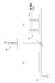
以下、本発明の第1の実施形態を、図面を参照して説明する。図2は図1のコントローラ5に付設される、加速度センサ4の有無を検出すべく設けたセンサ接続有無検出手段6の内部構造を示すブロック図であり、バイアス抵抗11、定電流パルス発生器12、第1比較器16を具備している。<First Embodiment>
DESCRIPTION OF EXEMPLARY EMBODIMENTS Hereinafter, a first embodiment of the invention will be described with reference to the drawings. FIG. 2 is a block diagram showing the internal structure of the sensor connection presence / absence detecting means 6 provided to detect the presence / absence of the
加速度センサ4は、バイアス抵抗11とともに一端側が接続端17に接続され、他端側がともに接地されて並列に取付けられている。 The
定電流パルス発生器12は、発振器13より出力される交番波から定電流パルスを生成し、加速度センサ4およびバイアス抵抗11の一端側である接続端17へ印加する。 The constant
加速度センサ4の他端はバイアス抵抗11とともにセンサアンプ14を介してピークホールド部15に接続される。ピークホールド部15で保持された電圧の最大値は第1比較器16に出力される。 The other end of the
第1比較器16は、定電流パルスを印加した際の接続端17の応答電圧(この実施形態ではセンサアンプ14で増幅した状態)の最大値VacMAX(図3参照)と所定の閾値である第1閾値Vth1とを比較し、前記接続端17の応答電圧の最大値VacMAXが前記第1閾値Vth1未満の場合はセンサ接続有りの信号を出力し、前記接続端17の応答電圧の最大値VacMAX(VrMAX)が前記第1閾値Vth1以上の場合(図4参照)はセンサ接続無しの信号を出力する。The
次に、図2のブロック図と図3、4の波形図を参照して、第1の実施形態の動作を説明する。 Next, the operation of the first embodiment will be described with reference to the block diagram of FIG. 2 and the waveform diagrams of FIGS.
圧電素子を用いた加速度センサ4は、電気的にはコンデンサと同じ容量性の特性を有する。すなわち、加速度センサ4に定電流を流すと電流の大きさと流した時間に比例した下記の電圧Vcが発生する。
Vc = I・t/C Vc:電圧 I:定電流 t:時間 C:加速度センサの容量The
Vc = I · t / C Vc: Voltage I: Constant current t: Time C: Accelerometer capacity
加速度センサ4がコントローラ5に接続されている場合は、定電流パルス発生器12で生成された定電流パルスは印加初期に大半が加速度センサ4に流れ込むので、加速度センサ4が検出した振幅波形Va(図3(a))に、定電流パルスによって発生した、上記電圧Vc(図3(b))が重畳される。重畳された電圧Vac(=Va+Vc)(図3(c))は、センサアンプ14によって増幅され、電圧の最大値VacMAXはピークホールド部15で保持されて第1比較器16へ出力される。When the
なお、図3(b)および(c)にはバイアス抵抗11の抵抗Rを無限大と仮定して電圧波形を描いている。バイアス抵抗11を考慮した場合、電流はバイアス抵抗11にも流れるので時間に比例した電圧とはならないが、パルス印加時間は十分短いので大きな差にはならない。 3B and 3C, voltage waveforms are drawn assuming that the resistance R of the
一方、加速度センサ4が接続されていない場合、接続端17に振幅波形は検出されず(図4(a))、加速度センサ4と並列的な関係にあるバイアス抵抗11に電流が流れ、定電流パルスと同期して時間と関係なく抵抗の大きさで決まる下記の一定の電圧Vr(図4(b))がパルス状に発生する。
Vr = I・R Vr:電圧 I:定電流 R:抵抗On the other hand, when the
Vr = I ・ R Vr: Voltage I: Constant current R: Resistance
この電圧のパルス波がセンサアンプ14によって増幅され、最大値VrMAXが図2に示すピークホールド部15で保持されて、第1比較器16へ出力される。The pulse wave of this voltage is amplified by the
このとき、定電流I、印加時間t、抵抗Rの値を適切に設定すれば、センサ接続の有無による発生電圧VacMAXとVrMAXの大きさが大きく異なり、閾値Vth1(第1閾値)を適切に設定することでセンサ接続の有無を判別できる。第1比較器16は、発生電圧の最大値が閾値Vth1未満の場合はセンサ接続有りの信号S1を出力し、発生電圧の最大値が閾値Vth1以上の場合はセンサ接続無しの信号S2を出力する。At this time, if the values of constant current I, application time t, and resistance R are set appropriately, the magnitudes of generated voltages VacMAX and VrMAX depending on the presence or absence of sensor connection differ greatly, and threshold Vth1 (first threshold) is appropriately set. By setting to, the presence or absence of sensor connection can be determined. The
参考として、定電流I、印加時間t、加速度センサの容量Cの各設定値と、その場合のセンサ接続有りの時の電圧Vcおよびセンサ接続無しのときの電圧Vrの値の例を、それぞれ以下に示す。
I = 1.8μA、t = 1.8mS、C = 10nFとして
Vc = 0.324V
Vr = 1.8VFor reference, examples of each set value of constant current I, application time t, acceleration sensor capacitance C, and voltage Vc when sensor is connected and voltage Vr when sensor is not connected are shown below. Shown in
I = 1.8μA, t = 1.8mS, C = 10nF
Vc = 0.324V
Vr = 1.8V
なお、上記Vcを求める際には、定電流パルスは印加初期に大半が加速度センサ4に流れ込むとしたので、バイアス抵抗11を無視(R = ∞)しVc = 0.324Vと算出した。この値と加速度センサ無しのときの電圧Vr = 1.8Vとの電圧差を利用することで、センサ接続の有無を判別できる。また、バイアス抵抗11の抵抗R = 1MΩ(数値は一例)を考慮して計算しても、
Vc = IR/(1 + CR/t)
に抵抗Rの値および前述のI, t, Cの値を代入して、Vc = 0.275Vとなるので、加速度センサ無しのときの電圧Vr = 1.8Vとの電圧差を利用することで、センサ接続の有無を判別できる。When obtaining the above Vc, it was assumed that most of the constant current pulse flowed into the
Vc = IR / (1 + CR / t)
Substituting the value of resistor R and the values of I, t, and C into Vc = 0.275V, so using the voltage difference from the voltage Vr = 1.8V without the acceleration sensor, Can determine if there is a connection.
なお上記の例における、加速度センサ4がない時(Rなし)/バイアス抵抗を考慮しない時(Cなし)/バイアス抵抗11を考慮する時(R,Cあり)それぞれの時間ごとの電圧値と電圧波形を図5に示す。 In the above example, when the
なお、以上の数値例はあくまで一例であって、これらに限定されるものではない。 In addition, the above numerical example is an example to the last, Comprising: It is not limited to these.
以上のように、本実施形態コントローラ5は、ボウル20に振動を発生させて部品を移送する振動運搬装置1に適用され、ボウル20に加速度センサ4を取り付けてボウル20の振動を計測するにあたり、加速度センサ4に並列に接続される位置に配置されるバイアス抵抗11と、加速度センサ4及びバイアス抵抗11の接続端17に定電流パルスを印加する定電流パルス発生器12と、定電流パルスを印加した際の接続端17における応答電圧の最大値VacMAX(VrMAX)と所定の閾値Vth1(第1閾値)とを比較し、応答電圧の最大値が第1閾値Vth1未満すなわちVacMAXである場合はセンサ接続有りの信号S1を出力し、応答電圧の最大値が前記第1閾値Vth1以上すなわちVrMAXである場合はセンサ接続無しの信号を出力する第1比較器16と、からなる加速度センサ有無検出手段6を備えたことを特徴とする。As described above, the
上記の構成により、本実施形態によれば加速度センサ4の接続有無を自動で検出することができる。
<第2実施形態>With the above configuration, according to the present embodiment, whether or not the
Second Embodiment
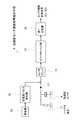
次に、本発明の第2実施形態を説明する。図6は図1のコントローラ5に付設される前記第1実施形態とは異なる構成のセンサ接続有無検出手段6を示すブロック図であり、図6中の符号は、第1の実施形態で既出の要素については同じ符号を付している。図6において、加速度センサ4はバイアス抵抗11とともに一端側に設けた接続端17がセンサアンプ14を介して減算回路25に接続され、他端側がともに接地されて並列に取付けられている。また、ダミーセンサ23は加速度センサ4と同じ容量性のコンデンサを採用したもので、加速度センサ4とほぼ同一の電気容量のものが用いられており、一端側がダミーセンサアンプ24を介して減算回路に接続され、他端側が接地されている。 Next, a second embodiment of the present invention will be described. FIG. 6 is a block diagram showing sensor connection presence / absence detection means 6 having a different configuration from that of the first embodiment attached to the
定電流パルス発生器12は、発振器13より出力される交番波から定電流パルスを生成し、加速度センサ4およびバイアス抵抗11の一端側である接続端17へ印加する。 The constant
定電流パルス発生器22は、発振器13より出力される交番波から定電流パルス発生器12で生成した定電流パルスとほぼ同じ(全く同じものも含む)定電流パルスを生成し、ダミーセンサ23の一端側である接続端27へ印加する。 The constant
定電流パルス発生器12、22から定電流パルスを印加された際に、接続端17には加速度センサ4の接続有無の状態に応じた応答電圧が現われ、接続端27にもダミーセンサ23の応答電圧が現われる。 When a constant current pulse is applied from the constant
減算回路25は、ダミーセンサアンプ24によって増幅されたダミーセンサ23の接続端27の電圧を、センサアンプ14によって増幅された加速度センサ4およびバイアス抵抗11の接続端17の電圧から減じる。 The
減算回路25の出力端はピークホールド部15およびバンドパスフィルタ31に接続され、ピークホールド部15は第2比較器26に接続される。バンドパスフィルタ31の出力は全波整流器32および位相検出器33に接続されている。全波整流器32は加速度信号(振幅信号)を、位相検出器33はゼロクロス信号(位相信号)をそれぞれインバータ34に出力する。そしてインバータ34はこれらの振幅及び位相に基づいて、所定の出力周波数と出力電圧で加振部3を駆動する。 The output terminal of the
第2比較器26は、前記減算回路25の出力電圧の最大値VsMAX(図7、図8参照)と所定の閾値である第2閾値Vth2とを比較し、前記減算回路25の出力電圧の最大値VsMAXが前記第2閾値Vth2未満の場合はセンサ接続有りの信号S1を出力し、前記減算回路25の出力電圧の最大値Vsmaxが前記第2閾値Vth2以上の場合はセンサ接続無しS2の信号を出力する。The
次に、図6のブロック図と図7、図8の波形図を参照して、第2の実施形態の動作を説明する。なお、以下に示される電圧値(図7、図8の波形図を含む)は全てセンサアンプ14もしくはダミーセンサアンプ24によって増幅した後のものとする。 Next, the operation of the second embodiment will be described with reference to the block diagram of FIG. 6 and the waveform diagrams of FIGS. The voltage values shown below (including the waveform diagrams of FIGS. 7 and 8) are all amplified by the
加速度センサ4がコントローラ5に接続されている場合は、定電流パルス発生器12で生成された定電流パルスは印加初期に大半が加速度センサ4に流れ込むので、加速度センサ4が検出した振幅波形Va(図7(a))に時間に比例した電圧Vc(図7(b))が重畳される(重畳後の電圧Vac=Va+Vc、図7(c))。 When the
また、ダミーセンサ23にもほぼ同じ定電流パルスが同じ時間印加されるので、ダミーセンサ23にも上記加速度センサによって発生した電圧Vcとほぼ等しい電圧Vc’(図7(d))が発生する。減算回路25は上記加速度センサ4の振幅波形VaにVcが重畳された電圧Vac(図7(c))からこの電圧Vc’を減じることで、重畳された波形(図7(c))の歪みを取り去ることができる(残留電圧Vs=Vac−Vc'、図7(e))。なお、減算回路25の出力(残留電圧)の最大値VsMAXはピークホールド部15に保持される。Further, since substantially the same constant current pulse is applied to the
一方、加速度センサ4が接続されていない場合は、加速度センサ4と並列的な関係にあるバイアス抵抗11に電流が流れ、定電流パルスと同期して時間と関係なく抵抗の大きさで決まる一定の電圧Vr(図8(b))がパルス状に発生する(図8(c))。このとき、ダミーセンサ23には定電流パルスが印加されているので、加速度センサ4が接続されている時と同様、電圧Vc’(図8(d))が発生している。減算回路25は上記定電流パルスが印加されることで生じるパルス電圧Vrからこの電圧Vc’を減算する(残留電圧Vs=Vr−Vc’、図8(e))。この場合も、減算回路25の出力(残留電圧)の最大値VsMAXはピークホールド部15に保持される。On the other hand, when the
加速度センサ4が接続されている場合には、減算回路25の出力(残留電圧)の最大値VsMAXはさほど大きくならないが、加速度センサ4が接続されていない場合には、減算回路25で減算対象となる上記一定のパルス電圧Vrに比べてダミーセンサ23による電圧Vc’が極めて小さく、パルス電圧Vr自体は一般に高い値を示すため、ピークホールド部15に保持された残留電圧Vsの最大値VsMAXは、加速度センサ4が接続されていない場合の最大値の方が加速度センサ4が接続されている場合の最大値と比べて大きくなる。よって、適切な閾値Vth2(第2閾値)を設定することで、第2比較器26によってセンサ接続の有無を判別することができる。第2比較器26は、発生電圧の最大値が閾値Vth2未満の場合はセンサ接続有りの信号S1を出力し、発生電圧の最大値が閾値Vth2以上の場合はセンサ接続無しの信号S2を出力する。When the
なおこの実施形態において、第2比較器26がセンサ有りの信号S1を出力している場合は、全波整流器32から加速度信号(振幅信号)を入力し、位相検出器33からゼロクロス信号(位相信号)を入力したインバータ34は、所定の出力周波数で所定の出力電圧を加振部3に出力することで加振部3の振動の駆動を行う。第2比較器26がセンサ接続無しの信号S2を出力している場合はフィードバック制御を停止し、出力周波数及び出力電圧の調整を手動モードに切替える。ここで手動モードとは、出力周波数と出力電圧を手動で入力することで振動を調整するように構成されたモードである。 In this embodiment, when the
以上のように、第2実施形態に係るコントローラ5は、ボウル20に振動を発生させて部品を移送する振動運搬装置1に適用され、ボウル20に加速度センサ4を取付けてボウル20の振動を計測するにあたり、加速度センサ4に並列に接続される位置に配置されるバイアス抵抗11と、加速度センサ4およびバイアス抵抗11の接続端17に定電流パルスを印加する定電流パルス発生器12と、加速度センサ4とほぼ同一の定電流パルスが印加される加速度センサ4とほぼ同一の電気容量のダミーセンサ23と、加速度センサ4及びバイアス抵抗11の接続端17に定電流パルスを印加した際の接続端17における応答電圧からダミーセンサ23の接続端27に定電流パルスを印加した際の接続端27における応答電圧を減じる減算回路と、加速度センサ4とほぼ同一の定電流パルスが印加される加速度センサ4とほぼ同一の電気容量のダミーセンサ23と、加速度センサ4の出力電圧からダミーセンサ23の出力電圧を減じる減算回路25と、減算回路25を経た後の残留電圧の最大値と所定の閾値Vth2(第2閾値)とを比較し、減算回路25の残留電圧の最大値が第2閾値未満の場合はセンサ接続有りの信号を出力し、加速度センサ4の出力電圧の最大値が第2閾値以上の場合はセンサ接続無しの信号を出力する第2比較器26と、からなる加速度センサ有無検出手段6を備えるように構成したものである。 As described above, the
上記の構成により、本実施形態によっても、加速度センサ4の接続有無を自動で検出することができる。また、減算回路25の作用によって、印加された定電流パルスの影響を受けて前記加速度センサ4の出力波形が歪むことはないため、加速度センサ4を稼働させながらその接続有無状態を適切に検出することができる。 With the above configuration, the present embodiment can also automatically detect whether the
そのダミーセンサ23にもコンデンサを採用することによって本発明を簡易に構成することができる。 By adopting a capacitor for the
さらに、第2の発明に係るコントローラ5において、ボウル20の振動波形から導かれる加速度及び位相に基づいて出力周波数及び出力電圧をフィードバック制御するフィードバック制御部30をさらに備えているので、加速度センサ4が接続されている場合は、フィードバック制御部30において減算処理後の信号にバンドパスフィルタ31を介した後、全波整流器32と位相検出器33によって全波整流と位相を取り出すことで、加速度センサ4の接続有無の検出手段を機能させつつ、ボウル20の振動のフィードバック制御を行うことができる。 Furthermore, the
また、第2の発明に係るコントローラ5に対して、フィードバック制御部30が、第2比較器26がセンサ接続有りの信号S1を出力している場合は振動波形によって出力周波数及び出力電圧をフィードバック制御し、第2比較器26がセンサ接続無しの信号S2を出力している場合はフィードバック制御を停止し出力周波数及び出力電圧の調整を手動モードに切替えるようにしているので、センサ接続有りの場合は通常のフィードバック制御を行いつつ、センサの断線などによる振幅信号の喪失に起因する過振幅を防止することができる。 For the
そして、第1の発明又は第2の発明に係るコントローラ5を振動運搬装置1に備えることで、加速度センサ4が振動運搬装置1のケース内に収容されているような場合にも、ケースを逐一開けて目視により確認等することなく、コントローラ5により振動運搬装置1の振動を制御するための加速度センサ4の接続を自動で検出することができる。 And by providing the
なお、上記実施形態において、ダミーセンサ23に図示しないバイアス抵抗(加速度センサ4と並行に接続されたバイアス抵抗11と同じ抵抗値)を並列に接続すれば、定電流パルスによって加速度センサ4に発生した電圧Vcとダミーセンサ23に発生した電圧Vc’の値はより近くなり、加速度センサ4からの出力波形をより正確に得ることができる。 In the above embodiment, if a bias resistor (not shown) (same resistance value as the
また、各部の具体的な構成は、上述した実施形態のみに限定されるものではない。例えば、上記実施例ではボウル型振動パーツフィーダを用いたが、直線的な振動を行うリニア振動フィーダにも本発明は適用可能である。また、加速度センサは圧電式に限られない。 In addition, the specific configuration of each unit is not limited to the above-described embodiment. For example, although the bowl-type vibrating part feeder is used in the above embodiment, the present invention can be applied to a linear vibrating feeder that performs linear vibration. The acceleration sensor is not limited to the piezoelectric type.
その他の構成も、本発明の趣旨を逸脱しない範囲で種々変形が可能である。 Other configurations can be variously modified without departing from the spirit of the present invention.
1…振動運搬装置
2…部品移送部
4…加速度センサ
5…制御装置(コントローラ)
6…加速度センサ接続有無検出手段
11…バイアス抵抗
12…定電流パルス発生器
16…第1比較器
17…接続端
22…定電流パルス発生器
23…ダミーセンサ(コンデンサ)
25…減算回路
26…第2比較器
30…フィードバック制御部DESCRIPTION OF
6 ... Acceleration sensor connection presence / absence detecting means 11 ...
25 ...
Claims (6)
Translated fromJapanese前記加速度センサに並列に接続される位置に配置されるバイアス抵抗と、
前記加速度センサ及び前記バイアス抵抗の接続端に定電流パルスを印加する定電流パルス発生器と、
前記定電流パルスを印加した際の前記接続端における応答電圧の最大値と所定の閾値である第1閾値とを比較し、前記応答電圧の最大値が前記第1閾値未満の場合はセンサ接続有りの信号を出力し、前記応答電圧の最大値が前記第1閾値以上の場合はセンサ接続無しの信号を出力する第1比較器と、
からなる加速度センサ有無検出手段を備えたことを特徴とする振動運搬装置の制御装置。In a control device that is applied to a vibration carrying device that generates a vibration in a component transfer unit and transfers a component, and measures an oscillation of the component transfer unit by attaching an acceleration sensor to the component transfer unit,
A bias resistor disposed at a position connected in parallel to the acceleration sensor;
A constant current pulse generator for applying a constant current pulse to a connection end of the acceleration sensor and the bias resistor;
The maximum value of the response voltage at the connection end when the constant current pulse is applied is compared with a first threshold value that is a predetermined threshold value. If the maximum value of the response voltage is less than the first threshold value, the sensor is connected. A first comparator that outputs a signal indicating no sensor connection when the maximum value of the response voltage is equal to or greater than the first threshold;
A control device for a vibration carrying device comprising an acceleration sensor presence / absence detecting means comprising
前記加速度センサに並列に接続される位置に配置されるバイアス抵抗と、
前記加速度センサ及び前記バイアス抵抗の接続端に定電流パルスを印加する定電流パルス発生器と、
前記加速度センサとほぼ同一の定電流パルスが印加される前記加速度センサとほぼ同一の電気容量のダミーセンサと、
前記加速度センサ及び前記バイアス抵抗の接続端に定電流パルスを印加した際の前記接続端における応答電圧から前記ダミーセンサの応答電圧を減じる減算回路と、
前記減算回路を経た後の残留電圧の最大値と所定の閾値である第2閾値とを比較し、前記減算回路の残留電圧の最大値が前記第2閾値未満の場合はセンサ接続有りの信号を出力し、前記減算回路の残留電圧の最大値が前記第2閾値以上の場合はセンサ接続無しの信号を出力する第2比較器と、
からなる加速度センサ有無検出手段を備えたことを特徴とする振動運搬装置の制御装置。In a control device for measuring vibration of the component transfer unit by applying an acceleration sensor to the component transfer unit, which is applied to a vibration carrying device that transfers vibration by generating vibration in the component transfer unit,
A bias resistor disposed at a position connected in parallel to the acceleration sensor;
A constant current pulse generator for applying a constant current pulse to a connection end of the acceleration sensor and the bias resistor;
A dummy sensor having substantially the same capacitance as the acceleration sensor to which a constant current pulse substantially the same as the acceleration sensor is applied;
A subtraction circuit that subtracts the response voltage of the dummy sensor from the response voltage at the connection end when a constant current pulse is applied to the connection end of the acceleration sensor and the bias resistor;
The maximum value of the residual voltage after passing through the subtracting circuit is compared with a second threshold value which is a predetermined threshold value. If the maximum value of the residual voltage value of the subtracting circuit is less than the second threshold value, a signal indicating sensor connection is obtained. A second comparator that outputs a signal indicating no sensor connection when the maximum value of the residual voltage of the subtraction circuit is equal to or greater than the second threshold;
A control device for a vibration carrying device, comprising: an acceleration sensor presence / absence detecting means comprising:
Priority Applications (1)
| Application Number | Priority Date | Filing Date | Title |
|---|---|---|---|
| JP2013116323AJP6136590B2 (en) | 2013-05-31 | 2013-05-31 | Control device for vibration carrying device and vibration carrying device |
Applications Claiming Priority (1)
| Application Number | Priority Date | Filing Date | Title |
|---|---|---|---|
| JP2013116323AJP6136590B2 (en) | 2013-05-31 | 2013-05-31 | Control device for vibration carrying device and vibration carrying device |
Publications (2)
| Publication Number | Publication Date |
|---|---|
| JP2014235067A JP2014235067A (en) | 2014-12-15 |
| JP6136590B2true JP6136590B2 (en) | 2017-05-31 |
Family
ID=52137890
Family Applications (1)
| Application Number | Title | Priority Date | Filing Date |
|---|---|---|---|
| JP2013116323AActiveJP6136590B2 (en) | 2013-05-31 | 2013-05-31 | Control device for vibration carrying device and vibration carrying device |
Country Status (1)
| Country | Link |
|---|---|
| JP (1) | JP6136590B2 (en) |
Families Citing this family (1)
| Publication number | Priority date | Publication date | Assignee | Title |
|---|---|---|---|---|
| JP7105043B2 (en)* | 2017-09-19 | 2022-07-22 | 日本電子株式会社 | Container supply unit and automatic analyzer |
Family Cites Families (4)
| Publication number | Priority date | Publication date | Assignee | Title |
|---|---|---|---|---|
| JP4013426B2 (en)* | 1999-11-26 | 2007-11-28 | 日立工機株式会社 | centrifuge |
| JP2002284332A (en)* | 2001-03-23 | 2002-10-03 | Tietech Co Ltd | Installation direction detection method for vibration sensor of vibrating carrying device |
| JP2002302231A (en)* | 2001-04-06 | 2002-10-18 | Shinko Electric Co Ltd | Piezoelectric driving type vibrating feeder |
| JP2002362723A (en)* | 2001-06-04 | 2002-12-18 | Ykk Corp | Parts feeder control method |
- 2013
- 2013-05-31JPJP2013116323Apatent/JP6136590B2/enactiveActive
Also Published As
| Publication number | Publication date |
|---|---|
| JP2014235067A (en) | 2014-12-15 |
Similar Documents
| Publication | Publication Date | Title |
|---|---|---|
| EP3090266B1 (en) | Resonant impedance sensing with a negative impedance control loop | |
| JP2012225664A (en) | Current sensor and current detection method | |
| JP6487396B2 (en) | Current detection circuit not affected by noise | |
| KR101077383B1 (en) | Inertia force sensor | |
| CN104535174A (en) | Mechanical resonance detecting device and method | |
| US20020140441A1 (en) | Method for controlling a transducer device in level sensors and device for carrying out such a method | |
| JP6136590B2 (en) | Control device for vibration carrying device and vibration carrying device | |
| US6429571B2 (en) | Method to control piezoelectric drives | |
| TW523429B (en) | Method and device for controlling part feeder | |
| US10006803B2 (en) | Sensor signal contact detector circuit | |
| JP5106816B2 (en) | Voltage measuring device and power measuring device | |
| CN112082617A (en) | Capacitive yarn sensor device with offset compensation | |
| KR102213528B1 (en) | Seismic acceleration sensor with leaf spring modulus control depending on temperature/humidity effect | |
| JP2006105900A (en) | Sensor circuit | |
| JP5758229B2 (en) | Magnetic field detector | |
| JP5387467B2 (en) | Vacuum gauge | |
| US20210293899A1 (en) | State analysis of an inductive operating resource | |
| JP2007240286A (en) | Measuring method and measuring device | |
| JP6450559B2 (en) | Measuring apparatus, measuring method and program | |
| JP5781902B2 (en) | Signal level measuring circuit and displacement measuring device having the same | |
| JP5558251B2 (en) | Integration circuit and voltage detection device | |
| JP6406620B2 (en) | Toner amount detection device and image forming apparatus | |
| JP6450557B2 (en) | Measuring apparatus, measuring method and program | |
| JP6380850B2 (en) | Toner amount detection device, image forming apparatus, and toner amount detection device adjustment method | |
| EP1367010A1 (en) | Parts feeder and control method thereof |
Legal Events
| Date | Code | Title | Description |
|---|---|---|---|
| A621 | Written request for application examination | Free format text:JAPANESE INTERMEDIATE CODE: A621 Effective date:20160412 | |
| A977 | Report on retrieval | Free format text:JAPANESE INTERMEDIATE CODE: A971007 Effective date:20170131 | |
| A131 | Notification of reasons for refusal | Free format text:JAPANESE INTERMEDIATE CODE: A131 Effective date:20170207 | |
| A521 | Request for written amendment filed | Free format text:JAPANESE INTERMEDIATE CODE: A523 Effective date:20170317 | |
| TRDD | Decision of grant or rejection written | ||
| A01 | Written decision to grant a patent or to grant a registration (utility model) | Free format text:JAPANESE INTERMEDIATE CODE: A01 Effective date:20170404 | |
| A61 | First payment of annual fees (during grant procedure) | Free format text:JAPANESE INTERMEDIATE CODE: A61 Effective date:20170417 | |
| R150 | Certificate of patent or registration of utility model | Ref document number:6136590 Country of ref document:JP Free format text:JAPANESE INTERMEDIATE CODE: R150 | |
| R250 | Receipt of annual fees | Free format text:JAPANESE INTERMEDIATE CODE: R250 | |
| R250 | Receipt of annual fees | Free format text:JAPANESE INTERMEDIATE CODE: R250 | |
| R250 | Receipt of annual fees | Free format text:JAPANESE INTERMEDIATE CODE: R250 | |
| R250 | Receipt of annual fees | Free format text:JAPANESE INTERMEDIATE CODE: R250 | |
| R250 | Receipt of annual fees | Free format text:JAPANESE INTERMEDIATE CODE: R250 | |
| R250 | Receipt of annual fees | Free format text:JAPANESE INTERMEDIATE CODE: R250 |