JP6135073B2 - Image forming apparatus - Google Patents
Image forming apparatusDownload PDFInfo
- Publication number
- JP6135073B2 JP6135073B2JP2012192712AJP2012192712AJP6135073B2JP 6135073 B2JP6135073 B2JP 6135073B2JP 2012192712 AJP2012192712 AJP 2012192712AJP 2012192712 AJP2012192712 AJP 2012192712AJP 6135073 B2JP6135073 B2JP 6135073B2
- Authority
- JP
- Japan
- Prior art keywords
- recording head
- image forming
- opening
- head
- unit
- Prior art date
- Legal status (The legal status is an assumption and is not a legal conclusion. Google has not performed a legal analysis and makes no representation as to the accuracy of the status listed.)
- Expired - Fee Related
Links
Images


Classifications
- B—PERFORMING OPERATIONS; TRANSPORTING
- B41—PRINTING; LINING MACHINES; TYPEWRITERS; STAMPS
- B41J—TYPEWRITERS; SELECTIVE PRINTING MECHANISMS, i.e. MECHANISMS PRINTING OTHERWISE THAN FROM A FORME; CORRECTION OF TYPOGRAPHICAL ERRORS
- B41J29/00—Details of, or accessories for, typewriters or selective printing mechanisms not otherwise provided for
- B41J29/02—Framework
- B—PERFORMING OPERATIONS; TRANSPORTING
- B41—PRINTING; LINING MACHINES; TYPEWRITERS; STAMPS
- B41J—TYPEWRITERS; SELECTIVE PRINTING MECHANISMS, i.e. MECHANISMS PRINTING OTHERWISE THAN FROM A FORME; CORRECTION OF TYPOGRAPHICAL ERRORS
- B41J2/00—Typewriters or selective printing mechanisms characterised by the printing or marking process for which they are designed
- B41J2/005—Typewriters or selective printing mechanisms characterised by the printing or marking process for which they are designed characterised by bringing liquid or particles selectively into contact with a printing material
- B41J2/01—Ink jet
- B41J2/135—Nozzles
- B41J2/165—Prevention or detection of nozzle clogging, e.g. cleaning, capping or moistening for nozzles
- B41J2/16505—Caps, spittoons or covers for cleaning or preventing drying out
- B41J2/16508—Caps, spittoons or covers for cleaning or preventing drying out connected with the printer frame
Landscapes
- Ink Jet (AREA)
- Particle Formation And Scattering Control In Inkjet Printers (AREA)
- Accessory Devices And Overall Control Thereof (AREA)
Description
Translated fromJapanese本発明は画像形成装置に関する。 The present invention relates to an image forming apparatus.
プリンタ、ファクシミリ、複写装置、プロッタ、これらの複合機等の画像形成装置として、例えばインク液滴を吐出する記録ヘッドを用いた液体吐出記録方式の画像形成装置としてインクジェット記録装置などが知られている。 As an image forming apparatus such as a printer, a facsimile machine, a copying apparatus, a plotter, and a complex machine of these, for example, an ink jet recording apparatus is known as an image forming apparatus of a liquid discharge recording method using a recording head for discharging ink droplets. .
従来の画像形成装置として、例えば、液滴を水平方向に吐出するように記録ヘッドを配置した画像形成部を備え、画像形成部に対向して被記録媒体を搬送する搬送機構部を備え、装置本体の開閉カバーに連動して搬送機構部が開くことで、搬送経路が開放されるようにして、ジャム処理を容易に行うことができるようにしたものが知られている(特許文献1)。 As a conventional image forming apparatus, for example, an image forming unit having a recording head disposed so as to eject liquid droplets in a horizontal direction, and a transport mechanism unit that transports a recording medium facing the image forming unit are provided. It is known that a jamming process can be easily performed by opening a conveyance mechanism unit in conjunction with an opening / closing cover of a main body so that a conveyance path is opened (Patent Document 1).
しかしながら、上述した特許文献1に開示の構成にあっては、ジャム処理は容易になるが、画像形成部の記録ヘッドの交換を行うことが難しいという課題がある。 However, in the configuration disclosed in
本発明は上記の課題に鑑みてなされたものであり、ジャム処理及びヘッド交換を容易に行うことができるようにすることを目的とする。 The present invention has been made in view of the above problems, and an object of the present invention is to make it possible to easily perform jam processing and head replacement.
上記の課題を解決するため、本発明の請求項1に係る画像形成装置は、
被記録媒体に画像形成する記録ヘッドを含む画像形成手段と、
前記画像形成手段に対向して前記被記録媒体を搬送する搬送手段と、
前記搬送手段に対して前記画像形成手段を挟んで反対側に配置された、装置本体に対して開閉可能な開閉カバーと、を備え、
前記記録ヘッドは、前記開閉カバーに着脱可能に装着され、
前記開閉カバーを開放位置にしたときに、前記記録ヘッドが前記搬送手段から離れる方向に移動し、
前記記録ヘッドは液滴を吐出する液体吐出ヘッドからなり、
前記記録ヘッドは水平方向に液滴を吐出する状態で装着され、
前記記録ヘッドが前記搬送手段から離れる方向に移動したときに、前記記録ヘッドのノズル面を覆うシャッタ部材を備えている
構成とした。In order to solve the above problems, an image forming apparatus according to
Image forming means including a recording head for forming an image on a recording medium;
A conveying unit that conveys the recording medium facing the image forming unit;
An opening / closing cover disposed on the opposite side of the image forming unit with respect to the conveying unit and capable of opening and closing with respect to the apparatus main body,
The recording head is detachably attached to the opening / closing cover,
When the open / close cover is set to the open position, the recording head moves in a direction away from the conveying means,
The recording head comprises a liquid ejection head that ejects droplets,
The recording head is mounted in a state of discharging droplets in the horizontal direction,
When the recording head ismoved in a direction away from the conveying means, and a configuration in which a shutter member that covers the nozzle face of the recording head.
本発明に係る画像形成装置によれば、ジャム処理及びヘッド交換を容易に行うことができる。 According to the image forming apparatus of the present invention, it is possible to easily perform jam processing and head replacement.
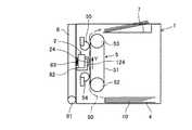
以下、本発明の実施の形態について添付図面を参照して説明する。まず、本発明の第1実施形態に係る画像形成装置について図1及び図2を参照して説明する。図1は同画像形成装置の開閉カバーを閉じた状態の模式的側面説明図、図2は同じく開閉カバーを開いた状態の模式的側面説明図である。 Embodiments of the present invention will be described below with reference to the accompanying drawings. First, an image forming apparatus according to a first embodiment of the present invention will be described with reference to FIGS. FIG. 1 is a schematic side view illustrating a state in which the open / close cover of the image forming apparatus is closed, and FIG. 2 is a schematic side view illustrating the state in which the open / close cover is also opened.
この画像形成装置は、ライン型画像形成装置であり、装置本体1の内部に、画像形成手段としての画像形成部2、搬送手段としての搬送機構部5等を有し、装置本体の下方側に被記録媒体である用紙10を積載可能な給紙部(給紙トレイ、給紙カセットなど)4を備えている。 This image forming apparatus is a line type image forming apparatus, and has an
そして、この給紙部4から用紙10を給紙して、搬送機構部5によって用紙10を垂直方向(鉛直方向に沿う方向)に搬送しながら、画像形成部2によって水平方向に液滴を吐出させて所要の画像を記録した後、画像が形成された用紙10を装置本体1の上方側に設けられた排紙部である排紙トレイ7に排紙する。 Then, the
装置本体1には、搬送機構部5に対して画像形成部2を挟んで反対側に配置された、装置本体1に対して開閉可能な前カバーである開閉カバー8を備えている。この開閉カバー8が設けられた側を装置本体1の前面側とする。 The apparatus
ここで、画像形成部2は、イエロー(Y)、マゼンタ(M)、シアン(C)、ブラック(K)の各色のインク滴を吐出するためのライン型液体吐出ヘッドからなる記録ヘッド24を備えている。なお、この例では、ライン型液体吐出ヘッドは、フルライン型液体吐出ヘッドでもよいし、あるいは、複数のヘッドを千鳥状にノズル配列方向(用紙送り方向Yと直交する方向)に配列したヘッドアレイ構成のものでもよい。また、記録ヘッドとして液体吐出ヘッドを使用しているが、これに限るものでない。 Here, the
そして、この記録ヘッド24は、開閉カバー8に設けられたヘッド保持部82に、着脱可能に、例えば用紙搬送方向と直交する方向(紙面垂直方向、以下同じ。)の両端部側を保持されて装着されている。 The
また、記録ヘッド24の背面側(ノズル面124と反対側)と開閉カバー8との間には、記録ヘッド24を滴吐出方向に向けて加圧する弾性部材83が設けられ、記録ヘッド24の姿勢(搬送機構部5に対する姿勢、ギャップを含む。)を保持される。 Further, an
搬送機構部5は、駆動ローラである搬送ローラ52と従動ローラ53との間に掛け渡した無端状の搬送ベルト51を有する。搬送ベルト51は、図示しない紙送りモータによってタイミングベルト及びタイミングプーリを介して搬送ローラ52が回転駆動されることによって、矢印Y方向(用紙送り方向)に周回移動して、画像形成部2の記録ヘッド24に対向して用紙10を垂直方向上方に搬送する。 The
また、記録ヘッド24の用紙搬送方向上流側及び下流側には、用紙10を押える拍車54、55が配置されている。 Further,
なお、給紙部4を装置本体1の上方側に配置し、排紙トレイ7を装置本体1の下方側に配置して、搬送機構部5が垂直方向上方から下方に向けて用紙10を搬送しながら画像形成を行う構成とすることもできる。 The paper feeding unit 4 is arranged on the upper side of the apparatus
開閉カバー8は、装置本体1の下端部に設けられた支軸81によって回転可能に保持され、装置本体1に対して図1に示す閉じた位置と、図2に示す開いた位置(開放位置)との間で開閉することが可能である。 The opening /
このように構成したので、ジャム処理を行うときには、図1に示すように、開閉カバー8が閉じた状態から、図2に示すように、開閉カバー8を矢印A方向に引き倒して、開閉カバー8を開放位置にする。 With this configuration, when performing jam processing, the opening /
これにより、図2に示すように、開閉カバー8とともに画像形成部2(記録ヘッド24)も開閉カバー8の開放移動に伴って搬送機構部5の搬送ベルト51面(搬送面)から離れる方向に移動し、記録ヘッド24と搬送ベルト51との間の搬送路50が開放される。 As a result, as shown in FIG. 2, the image forming unit 2 (recording head 24) together with the opening /
したがって、搬送ベルト51上で生じているジャム紙を容易に取り除くことができる。ジャム処理後は図1に示すように開閉カバー8を閉じる。 Therefore, the jammed paper generated on the
次に、ヘッド交換について図3を参照して説明する。図3は同ヘッド交換手順の説明に供する模式的側面説明図である。 Next, head replacement will be described with reference to FIG. FIG. 3 is a schematic side view for explaining the head replacement procedure.
まず、前述したジャム処理時と同様に、開閉カバー8が閉じた状態から、図2に示すように、開閉カバー8を矢印A方向に引き倒して、開閉カバー8を開放位置にする。 First, as in the case of the jam processing described above, from the state in which the opening /
そして、図3(a)に示すように、開閉カバー8のヘッド保持部82から記録ヘッド24を取り外し、図3(b)に示すように、交換後の記録ヘッド24を矢印C方向から開閉カバー8のヘッド保持部82に装着する。 3A, the
この場合、開閉カバー8が開いている状態で記録ヘッド24をヘッド保持部82に装着した状態では、記録ヘッド24がヘッド保持部82に対して多少動ける余裕があるようにする。 In this case, when the
そして、開閉カバー8を閉じたときに、装置本体1側に設けた位置決め部と記録ヘッド24が接触し、開閉カバー8側に設けられた弾性部材(加圧手段)83による加圧力で装置本体側に記録ヘッド24が押されて、装置本体1側の位置決め部に押し付けられ、装置本体1に対して位置決めされるようにすることが好ましい。 When the opening /
この場合、装置本体1側及び記録ヘッド24側に互いのノズル配列方向の位置、滴吐出方向、用紙搬送方向それぞれの位置を決めるための位置決め部を設け、それぞれの位置決め部が突き当たるように加圧する弾性部材などの加圧手段を備えることが好ましい。 In this case, positioning units for determining the positions in the nozzle arrangement direction, the droplet discharge direction, and the paper transport direction are provided on the apparatus
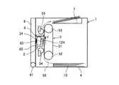
次に、本発明の第2実施形態に係る画像形成装置について図4及び図5を参照して説明する。図4は同画像形成装置の開閉カバーを閉じた状態の模式的側面説明図、図5は同じく開閉カバーを開いた状態の模式的側面説明図である。 Next, an image forming apparatus according to a second embodiment of the present invention will be described with reference to FIGS. 4 is a schematic side view illustrating the image forming apparatus with the open / close cover closed, and FIG. 5 is a schematic side view illustrating the open / close cover similarly.
本実施形態では、記録ヘッド24が垂直方向下向きに液滴を吐出し、搬送機構部5が用紙10を記録ヘッド24に対向して水平方向(矢印X方向)に搬送するように構成している。 In the present embodiment, the
このように構成した場合でも、図5に示すように、開閉カバー8を開くことで、搬送路50が開放され、ジャム処理や記録ヘッド24の交換も容易に行うことができる。 Even in such a configuration, as shown in FIG. 5, by opening the opening /
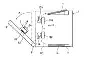
次に、本発明の第3実施形態に係る画像形成装置ついて図6を参照して説明する。図6は同画像形成装置の開閉カバーを開いた状態の模式的側面説明図である。 Next, an image forming apparatus according to a third embodiment of the present invention will be described with reference to FIG. FIG. 6 is a schematic side view of the image forming apparatus in a state where the opening / closing cover is opened.
本実施形態では、搬送機構部5は、画像形成部2の用紙搬送方向上流側に配置したプラテン152とローラ(又は拍車)154、用紙搬送方向下流側に配置したプラテン153とローラ(又は拍車)155で用紙10を搬送する構成としたものである。 In the present embodiment, the
このように構成しても、前記各実施形態と同様な作用効果を得ることができる。 Even if comprised in this way, the effect similar to each said embodiment can be acquired.
次に、本発明の第4実施形態に係る画像形成装置ついて図7を参照して説明する。図7は同画像形成装置の開閉カバーを開いた状態の模式的側面説明図である。 Next, an image forming apparatus according to a fourth embodiment of the present invention will be described with reference to FIG. FIG. 7 is a schematic side view illustrating the image forming apparatus with the open / close cover opened.
本実施形態は、前記第3実施形態の搬送機後部5を前記第2実施形態の構成に適用したものである。 In this embodiment, the
このように構成しても、前記各実施形態と同様な作用効果を得ることができる。 Even if comprised in this way, the effect similar to each said embodiment can be acquired.
次に、本発明の第5実施形態に係る画像形成装置ついて図8及び図9を参照して説明する。図8は同画像形成装置の開閉カバーを閉じた状態の模式的側面説明図、図9は同じく開閉カバーを開いた状態の模式的側面説明図である。 Next, an image forming apparatus according to a fifth embodiment of the present invention will be described with reference to FIGS. FIG. 8 is a schematic side view illustrating the image forming apparatus with the open / close cover closed, and FIG. 9 is a schematic side view illustrating the open / close cover similarly.
本実施形態では、前記第1実施形態の画像形成装置において、開閉カバー8を開いたときに記録ヘッド24のノズル面124を覆う保護部材としてのシャッタ部材6を備えている。このシャッタ部材6は、開閉カバー8を閉じたときには、記録ヘッド24のノズル面124を覆う位置から退避した位置になる。 In the present embodiment, the image forming apparatus of the first embodiment includes a shutter member 6 as a protective member that covers the
これにより、開閉カバー8を開いたときに記録ヘッド24のノズル面に他の部材などが接触してノズル面が損傷することを防止できる。 Thereby, when the opening /
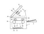
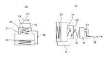
次に、シャッタ部材を含むシャッタ機構の一例について図10を参照して説明する。図10は同シャッタ機構の一例を示す側面説明図である。 Next, an example of a shutter mechanism including a shutter member will be described with reference to FIG. FIG. 10 is an explanatory side view showing an example of the shutter mechanism.
ここでは、シャッタ部材6は、記録ヘッド24のノズル面124を覆うための保護部61を有し、保護部61の両端部(用紙搬送方向と直交する方向)には支持部62が設けられている。 Here, the shutter member 6 has a
そして、シャッタ部材6の支持部62は、中間部が開閉カバー8に設けられた支軸63に回転可能に支持され、後端部(シャッタ部材6と反対側の端部)には錘64が設けられている。 The
このように構成することで、図10(a)、(b)に示すように、錘64によってシャッタ部材6は、常に錘64が垂直方向下側に位置するため、保護部61が上方に位置する姿勢に保持される。 With such a configuration, as shown in FIGS. 10A and 10B, the shutter member 6 is always positioned on the lower side in the vertical direction by the
したがって、開閉カバー8が閉じているときには、図10(a)に示すように、記録ヘッド24が水平方向に液滴を吐出する姿勢になる。このとき、シャッタ部材6の保護部61は記録ヘッド24のノズル面124から離れた状態になる。 Therefore, when the open /
そして、開閉カバー8が開放位置にされたときには、図10(b)に示すように、記録ヘッド24が垂直方向上方を向く姿勢になり、このときシャッタ部材6の保護部61の位置は変化しないので、記録ヘッド24のノズル面124に対してシャッタ部材6の保護部61はノズル面124を覆う状態になる。 When the open /
したがって、開閉カバー8を開いたときには、記録ヘッド24のノズル面124はシャッタ部材6の保護部61で保護される。 Therefore, when the opening /
なお、本実施形態では、記録ヘッド24の姿勢が変化することで保護部材としてシャッタ部材との相対位置関係が、シャッタ部材でノズル面が保護される位置とシャッタ部材がノズル面から離れた位置とに変化する例で説明しているが、これに限るものではない。 In the present embodiment, the relative position of the
例えば、記録ヘッド24の前面側で例えばノズルに対応する開口を有するシャッタが開閉カバーの開閉動作に連動して、開口がノズルに対応する位置とノズルの前方を覆う位置との間で変位するような構成とすることもできる。 For example, a shutter having an opening corresponding to the nozzle, for example, on the front side of the
次に、本発明の第6実施形態に係る画像形成装置ついて図11を参照して説明する。図11は同画像形成装置におけるキャップ部材部分の模式的側面説明図である。 Next, an image forming apparatus according to a sixth embodiment of the present invention will be described with reference to FIG. FIG. 11 is a schematic side view of a cap member portion in the image forming apparatus.
本実施形態では、少なくとも開閉カバー8を開いたときに記録ヘッド24のノズル面124を覆うキャップ部材65を備えている。 In the present embodiment, a
ここでは、図11(a)に示すように、開閉カバー8を開いた状態で、記録ヘッド24のノズル面124を覆うキャップ部材65を備えている。このキャップ部材65は、記録ヘッド24との間に設けた弾性部材66によってノズル面124に押し付けられている。 Here, as shown in FIG. 11A, a
そして、図11(b)に示すように、装置本体1側には引っ張り部材68が配置され、開閉カバー8を閉じたときに、キャップ部材65のフック部67が装置本体1側の引っ張り部材68に係わり合った状態になるようにしている。 As shown in FIG. 11B, a
ここで、引っ張り部材68が矢印方向に引かれることで、キャップ部材65が記録ヘッド24のノズル面124から離間して画像形成可能状態にする。 Here, the pulling
このように、記録ヘッド24のノズル面をキャッピングするキャップ部材65を備えていることで、ヘッド交換時に、取り外した後の記録ヘッド24も、取り付ける前の記録ヘッド24もノズル面がキャップ部材65によって覆われているため、ノズルの損傷を防ぐことができる。 As described above, since the
この実施形態では、前記第3実施形態のように、プラテン152とプラテン153との間に、キャップ部材65が収まるように構成することが好ましい。 In this embodiment, as in the third embodiment, it is preferable that the
次に、本発明の第7実施形態に係る画像形成装置ついて図12及び図13を参照して説明する。図12は同画像形成装置の開閉カバーを閉じた状態の模式的側面説明図、図12は同じく開閉カバーを閉じた状態の模式的側面説明図である。 Next, an image forming apparatus according to a seventh embodiment of the present invention will be described with reference to FIGS. FIG. 12 is a schematic side view illustrating the image forming apparatus with the open / close cover closed, and FIG. 12 is a schematic side view illustrating the image cover with the open / close cover closed.
本実施形態では、開閉カバー8と搬送機構部5との間に、ヘッド支持部材9を回転可能に配置している。そして、開閉カバー8に記録ヘッド24を保持する場合と同様に、ヘッド支持部材9に設けたヘッド支持部92に記録ヘッド24を着脱可能に装着している。また、記録ヘッド24の背面とヘッド支持部材9との間に弾性部材93を配置している。 In the present embodiment, the
ここで、ヘッド支持部材9は、開閉カバー8の開閉動作に連動して移動する。つまり、図13に示すように、開閉カバー8を開いたときに、ヘッド支持部材9は記録ヘッド24が搬送機構部5から離れる方向に移動し、図12に示すように、開閉カバー8を閉じたときに、ヘッド支持部材9は記録ヘッド24が搬送機構部5に向かう方向に移動する。 Here, the
この場合、開閉カバー8とヘッド支持部材9との連動機構は、例えば開閉カバー8とヘッド支持部材9とをリンク機構で連結し、開閉カバー8が所定量開くまでは開閉カバー8が単独で開放位置に向けて回転し、所定量開いたときにリンク機構とヘッド支持部材9とが連結されて、ヘッド支持部材9も開放方向に回転するようにすればよい。 In this case, the interlock mechanism between the opening /
このように構成することで、開閉カバー8の開放位置とは別にヘッド交換時の記録ヘッド24の姿勢を決めることができる。 With this configuration, the posture of the
また、画像形成部2をシリアル型で構成する場合に、記録ヘッドを搭載するキャリッジ及びキャリッジを主走査方向に移動走査させるキャリッジ駆動機構などをキャリッジユニットとして構成し、このキャリッジユニットをヘッド支持部材上に着脱可能に装着する構成を容易に取ることもできるようになる。このように、画像形成手段の構成の自由度が増し、開閉カバーの開閉操作の操作性の向上も図れる。 When the
なお、本願において、「用紙」とは材質を紙に限定するものではなく、OHP、布、ガラス、基板などを含み、インク滴、その他の液体、画像形成剤などが付着可能なものの意味であり、被記録媒体、記録媒体、記録紙、記録用紙などと称されるものを含む。また、画像形成、記録、印字、印写、印刷はいずれも同義語とする。 In the present application, the “paper” is not limited to paper, but includes OHP, cloth, glass, a substrate, etc., and can be attached to ink droplets, other liquids, image forming agents, and the like. , Recording media, recording media, recording paper, recording paper, and the like. In addition, image formation, recording, printing, printing, and printing are all synonymous.
また、「画像形成装置」は、紙、糸、繊維、布帛、皮革、金属、プラスチック、ガラス、木材、セラミックス等の媒体に液体や画像形成剤を付与して画像形成を行う装置を意味し、また、「画像形成」とは、文字や図形等の意味を持つ画像を媒体に対して付与することだけでなく、パターン等の意味を持たない画像を媒体に付与すること(単に液滴や画像形成剤を媒体に付与すること)をも意味する。 The “image forming apparatus” means an apparatus for forming an image by applying a liquid or an image forming agent to a medium such as paper, thread, fiber, fabric, leather, metal, plastic, glass, wood, ceramics, In addition, “image formation” means not only that an image having a meaning such as a character or a figure is applied to the medium but also an image having no meaning such as a pattern or the like (simply a droplet or an image). It also means that the forming agent is applied to the medium.
また、「インク」とは、特に限定しない限り、インクと称されるものに限らず、記録液、定着処理液、液体などと称されるものなど、画像形成を行うことができるすべての液体の総称として用い、例えば、DNA試料、レジスト、パターン材料、樹脂なども含まれる。 The “ink” is not limited to an ink unless otherwise specified, but includes any liquid that can form an image, such as a recording liquid, a fixing processing liquid, or a liquid. Used generically, for example, includes DNA samples, resists, pattern materials, resins, and the like.
また、「画像」とは平面的なものに限らず、立体的に形成されたものに付与された画像、また立体自体を三次元的に造形して形成された像も含まれる。 In addition, the “image” is not limited to a planar image, and includes an image given to a three-dimensionally formed image and an image formed by three-dimensionally modeling a solid itself.
また、本願における滴吐出方向としての「水平方向」とは、垂直方向以外の方向の意味(水平に対して斜め上方又は下方に傾いた方向を含む意味)、用紙搬送方向としての「垂直方向」とは、水平以外の方向の意味(垂直に対して斜め上方又は下方に傾いた方向を含む意味)である。 Further, the “horizontal direction” as the droplet discharge direction in the present application means a direction other than the vertical direction (including a direction inclined obliquely upward or downward with respect to the horizontal), and the “vertical direction” as the paper transport direction. Means a direction other than horizontal (including a direction inclined obliquely upward or downward with respect to vertical).
2 画像形成部
4 給紙部
5 搬送機構部
7 排紙トレイ
8 開閉カバー
9 ヘッド支持部材
24 記録ヘッド
51 搬送ベルト
82、92 ヘッド支持部DESCRIPTION OF
Claims (7)
Translated fromJapanese前記画像形成手段に対向して前記被記録媒体を搬送する搬送手段と、
前記搬送手段に対して前記画像形成手段を挟んで反対側に配置された、装置本体に対して開閉可能な開閉カバーと、を備え、
前記記録ヘッドは、前記開閉カバーに着脱可能に装着され、
前記開閉カバーを開放位置にしたときに、前記記録ヘッドが前記搬送手段から離れる方向に移動し、
前記記録ヘッドは液滴を吐出する液体吐出ヘッドからなり、
前記記録ヘッドは水平方向に液滴を吐出する状態で装着され、
前記記録ヘッドが前記搬送手段から離れる方向に移動したときに、前記記録ヘッドのノズル面を覆うシャッタ部材を備えている
ことを特徴とする画像形成装置。Image forming means including a recording head for forming an image on a recording medium;
A conveying unit that conveys the recording medium facing the image forming unit;
An opening / closing cover disposed on the opposite side of the image forming unit with respect to the conveying unit and capable of opening and closing with respect to the apparatus main body,
The recording head is detachably attached to the opening / closing cover,
When the open / close cover is set to the open position, the recording head moves in a direction away from the conveying means,
The recording head comprises a liquid ejection head that ejects droplets,
The recording head is mounted in a state of discharging droplets in the horizontal direction,
Wherein when the recording head ismoved in a direction away from the conveying means, an image forming apparatus characterized by comprising a shutter member that covers the nozzle face of the recording head.
前記画像形成手段に対向して前記被記録媒体を搬送する搬送手段と、
前記搬送手段に対して前記画像形成手段を挟んで反対側に配置された、装置本体に対して開閉可能な開閉カバーと、
前記開閉カバーの開閉動作に連動するヘッド保持部材と、を備え、
前記記録ヘッドは、前記ヘッド保持部材に着脱可能に装着され、
前記開閉カバーを開放位置にしたときに、前記ヘッド保持部材は前記記録ヘッドが前記搬送手段から離れる方向に移動し、
前記記録ヘッドは液滴を吐出する液体吐出ヘッドからなり、
前記記録ヘッドは水平方向に液滴を吐出する状態で装着され、
前記記録ヘッドが前記搬送手段から離れる方向に移動したときに、前記記録ヘッドのノズル面を覆うシャッタ部材を備えている
ことを特徴とする画像形成装置。Image forming means including a recording head for forming an image on a recording medium;
A conveying unit that conveys the recording medium facing the image forming unit;
An opening / closing cover that is disposed on the opposite side of the image forming unit with respect to the conveying unit and that can be opened and closed with respect to the apparatus main body;
A head holding member that interlocks with the opening and closing operation of the opening and closing cover,
The recording head is detachably attached to the head holding member,
When the open / close cover is set to the open position, the head holding member moves in a direction in which the recording head moves away from the transport unit,
The recording head comprises a liquid ejection head that ejects droplets,
The recording head is mounted in a state of discharging droplets in the horizontal direction,
Wherein when the recording head ismoved in a direction away from the conveying means, an image forming apparatus characterized by comprising a shutter member that covers the nozzle face of the recording head.
前記画像形成手段に対向して前記被記録媒体を搬送する搬送手段と、
前記搬送手段に対して前記画像形成手段を挟んで反対側に配置された、装置本体に対して開閉可能な開閉カバーと、を備え、
前記記録ヘッドは、前記開閉カバーに着脱可能に装着され、
前記開閉カバーを開放位置にしたときに、前記記録ヘッドが前記搬送手段から離れる方向に移動し、
前記記録ヘッドは液滴を吐出する液体吐出ヘッドからなり、
前記記録ヘッドは水平方向に液滴を吐出する状態で装着され、
前記記録ヘッドが前記搬送手段から離れる方向に移動するときに、前記記録ヘッドのノズル面を覆う状態に移動するキャップ部材を備えている
ことを特徴とする画像形成装置。Image forming means including a recording head for forming an image on a recording medium;
A conveying unit that conveys the recording medium facing the image forming unit;
An opening / closing cover disposed on the opposite side of the image forming unit with respect to the conveying unit and capable of opening and closing with respect to the apparatus main body,
The recording head is detachably attached to the opening / closing cover,
When the open / close cover is set to the open position, the recording head moves in a direction away from the conveying means,
The recording head comprises a liquid ejection head that ejects droplets,
The recording head is mounted in a state of discharging droplets in the horizontal direction,
An image forming apparatus comprising: a cap member that moves to cover the nozzle surface of the recording head when the recording head moves in a direction away from the conveying unit.
前記画像形成手段に対向して前記被記録媒体を搬送する搬送手段と、
前記搬送手段に対して前記画像形成手段を挟んで反対側に配置された、装置本体に対して開閉可能な開閉カバーと、
前記開閉カバーの開閉動作に連動するヘッド保持部材と、を備え、
前記記録ヘッドは、前記ヘッド保持部材に着脱可能に装着され、
前記開閉カバーを開放位置にしたときに、前記ヘッド保持部材は前記記録ヘッドが前記搬送手段から離れる方向に移動し、
前記記録ヘッドは液滴を吐出する液体吐出ヘッドからなり、
前記記録ヘッドは水平方向に液滴を吐出する状態で装着され、
前記記録ヘッドが前記搬送手段から離れる方向に移動するときに、前記記録ヘッドのノズル面を覆う状態に移動するキャップ部材を備えている
ことを特徴とする画像形成装置。Image forming means including a recording head for forming an image on a recording medium;
A conveying unit that conveys the recording medium facing the image forming unit;
An opening / closing cover that is disposed on the opposite side of the image forming unit with respect to the conveying unit and that can be opened and closed with respect to the apparatus main body;
A head holding member that interlocks with the opening and closing operation of the opening and closing cover,
The recording head is detachably attached to the head holding member,
When the open / close cover is set to the open position, the head holding member moves in a direction in which the recording head moves away from the transport unit,
The recording head comprises a liquid ejection head that ejects droplets,
The recording head is mounted in a state of discharging droplets in the horizontal direction,
An image forming apparatus comprising: a cap member that moves to cover the nozzle surface of the recording head when the recording head moves in a direction away from the conveying unit.
Priority Applications (2)
| Application Number | Priority Date | Filing Date | Title |
|---|---|---|---|
| JP2012192712AJP6135073B2 (en) | 2012-09-01 | 2012-09-01 | Image forming apparatus |
| US14/011,331US9039137B2 (en) | 2012-09-01 | 2013-08-27 | Image forming apparatus |
Applications Claiming Priority (1)
| Application Number | Priority Date | Filing Date | Title |
|---|---|---|---|
| JP2012192712AJP6135073B2 (en) | 2012-09-01 | 2012-09-01 | Image forming apparatus |
Publications (2)
| Publication Number | Publication Date |
|---|---|
| JP2014046628A JP2014046628A (en) | 2014-03-17 |
| JP6135073B2true JP6135073B2 (en) | 2017-05-31 |
Family
ID=50186970
Family Applications (1)
| Application Number | Title | Priority Date | Filing Date |
|---|---|---|---|
| JP2012192712AExpired - Fee RelatedJP6135073B2 (en) | 2012-09-01 | 2012-09-01 | Image forming apparatus |
Country Status (2)
| Country | Link |
|---|---|
| US (1) | US9039137B2 (en) |
| JP (1) | JP6135073B2 (en) |
Families Citing this family (7)
| Publication number | Priority date | Publication date | Assignee | Title |
|---|---|---|---|---|
| US9108442B2 (en) | 2013-08-20 | 2015-08-18 | Ricoh Company, Ltd. | Image forming apparatus |
| JP6394297B2 (en) | 2014-11-07 | 2018-09-26 | 株式会社リコー | Image forming apparatus |
| JP6566315B2 (en) | 2015-10-15 | 2019-08-28 | 株式会社リコー | Image forming apparatus |
| JP7271876B2 (en) | 2018-08-31 | 2023-05-12 | 株式会社リコー | Droplet ejection device and image forming device |
| JP7342537B2 (en) | 2019-09-04 | 2023-09-12 | 株式会社リコー | Device that discharges liquid |
| JP7342538B2 (en) | 2019-09-04 | 2023-09-12 | 株式会社リコー | Device that discharges liquid |
| US11420442B2 (en) | 2020-02-14 | 2022-08-23 | Ricoh Company, Ltd. | Liquid discharge apparatus |
Family Cites Families (37)
| Publication number | Priority date | Publication date | Assignee | Title |
|---|---|---|---|---|
| JP2575349B2 (en)* | 1985-03-28 | 1997-01-22 | キヤノン株式会社 | Image forming device |
| JP2641200B2 (en)* | 1986-12-10 | 1997-08-13 | キヤノン株式会社 | Ink jet recording device |
| JPH0546926Y2 (en)* | 1987-04-24 | 1993-12-09 | ||
| EP0541519B1 (en)* | 1988-09-07 | 1997-01-22 | Seiko Epson Corporation | Ink jet printer sealing method and apparatus |
| JP2801409B2 (en) | 1989-12-26 | 1998-09-21 | キヤノン株式会社 | Inkjet device and recording unit cartridge |
| JPH082754A (en)* | 1994-06-22 | 1996-01-09 | Matsushita Graphic Commun Syst Inc | Ink jet recording device |
| US6328415B1 (en)* | 1999-04-30 | 2001-12-11 | Hewlett-Packard Company | Displaceable print cartridge chute |
| US7079712B1 (en)* | 1999-05-25 | 2006-07-18 | Silverbrook Research Pty Ltd | Method and system for providing information in a document |
| JP2003127402A (en)* | 2001-10-22 | 2003-05-08 | Canon Inc | Inkjet recording device |
| US6637858B2 (en)* | 2001-10-30 | 2003-10-28 | Hewlett-Packard Development Company, L.P. | Printing mechanism hinged printbar assembly |
| JP2004009404A (en)* | 2002-06-05 | 2004-01-15 | Ricoh Co Ltd | Inkjet recording device |
| JP2005169680A (en)* | 2003-12-08 | 2005-06-30 | Sony Corp | Discharge face protecting device, liquid discharging cartridge, liquid discharging apparatus and discharge face cleaning method |
| JP4507583B2 (en) | 2003-12-12 | 2010-07-21 | ソニー株式会社 | Ejection surface protection device, liquid ejection cartridge, and liquid ejection device |
| US7448734B2 (en) | 2004-01-21 | 2008-11-11 | Silverbrook Research Pty Ltd | Inkjet printer cartridge with pagewidth printhead |
| CA2550777C (en) | 2004-01-21 | 2010-05-11 | Silverbrook Research Pty Ltd | Inkjet printer system with removable cartridge |
| CA2588645C (en)* | 2004-12-20 | 2010-08-03 | Silverbrook Research Pty Ltd | Wall mountable printer with removable cartridge |
| US7735994B2 (en)* | 2004-12-20 | 2010-06-15 | Silverbrook Research Pty Ltd | Wall mountable printer with removable cartridge |
| JP4541871B2 (en) | 2004-12-21 | 2010-09-08 | 株式会社セイコーアイ・インフォテック | Maintenance unit and inkjet printer |
| JP4975492B2 (en) | 2007-03-19 | 2012-07-11 | 株式会社リコー | Image forming apparatus |
| JP4910965B2 (en)* | 2007-09-28 | 2012-04-04 | セイコーエプソン株式会社 | Thermal printer |
| US8042910B2 (en)* | 2008-05-29 | 2011-10-25 | Hewlett-Packard Development Company, L.P. | Replaceable printbar assembly |
| JP5576138B2 (en)* | 2010-02-10 | 2014-08-20 | シチズンホールディングス株式会社 | Thermal printer |
| JP5594586B2 (en) | 2010-08-26 | 2014-09-24 | 株式会社リコー | Image forming apparatus |
| JP5533457B2 (en) | 2010-09-02 | 2014-06-25 | 株式会社リコー | Image forming apparatus |
| JP5316506B2 (en)* | 2010-09-30 | 2013-10-16 | ブラザー工業株式会社 | Liquid ejection device |
| JP5659739B2 (en) | 2010-11-30 | 2015-01-28 | 株式会社リコー | Image forming apparatus |
| JP2012121147A (en) | 2010-12-06 | 2012-06-28 | Ricoh Co Ltd | Image forming apparatus |
| JP5364738B2 (en)* | 2011-02-18 | 2013-12-11 | シチズンホールディングス株式会社 | Thermal printer |
| JP2012179791A (en) | 2011-03-01 | 2012-09-20 | Ricoh Co Ltd | Image forming apparatus |
| JP5732914B2 (en) | 2011-03-02 | 2015-06-10 | 株式会社リコー | Image forming apparatus |
| JP5382044B2 (en)* | 2011-03-31 | 2014-01-08 | ブラザー工業株式会社 | Recording device |
| JP5810656B2 (en) | 2011-06-15 | 2015-11-11 | 株式会社リコー | Image forming apparatus |
| JP5016126B2 (en) | 2011-07-04 | 2012-09-05 | 株式会社リコー | Image forming unit and moving unit |
| JP5957880B2 (en) | 2011-12-27 | 2016-07-27 | 株式会社リコー | Droplet discharge apparatus and image forming apparatus |
| JP5935338B2 (en) | 2012-01-16 | 2016-06-15 | 株式会社リコー | Image forming apparatus |
| JP5899968B2 (en) | 2012-01-31 | 2016-04-06 | 株式会社リコー | Image forming apparatus |
| JP5472356B2 (en) | 2012-03-30 | 2014-04-16 | 株式会社リコー | Image forming apparatus |
- 2012
- 2012-09-01JPJP2012192712Apatent/JP6135073B2/ennot_activeExpired - Fee Related
- 2013
- 2013-08-27USUS14/011,331patent/US9039137B2/ennot_activeExpired - Fee Related
Also Published As
| Publication number | Publication date |
|---|---|
| US20140063121A1 (en) | 2014-03-06 |
| US9039137B2 (en) | 2015-05-26 |
| JP2014046628A (en) | 2014-03-17 |
Similar Documents
| Publication | Publication Date | Title |
|---|---|---|
| JP6135073B2 (en) | Image forming apparatus | |
| JP5181686B2 (en) | Image forming apparatus | |
| JP6236814B2 (en) | Image forming apparatus | |
| US8251507B2 (en) | Inkjet recording apparatus | |
| US8132905B2 (en) | Recording device having a conveying unit that conveys a recording medium | |
| JP4877259B2 (en) | Recording device | |
| US8297733B2 (en) | Ink jet recording apparatus having recovery device | |
| JP2009160778A (en) | Image forming apparatus | |
| JP5879924B2 (en) | Image forming apparatus | |
| US7434928B2 (en) | Image forming apparatus | |
| JP4869412B2 (en) | Inkjet recording apparatus and image forming apparatus | |
| JP5780015B2 (en) | Paper processing apparatus and image forming apparatus | |
| JP6217262B2 (en) | Image forming apparatus and liquid discharge head unit | |
| JP4535188B2 (en) | Recording device | |
| JP2006111002A (en) | Image forming apparatus and conveying apparatus | |
| JP6191431B2 (en) | Image forming apparatus | |
| JP5780448B2 (en) | Image forming apparatus | |
| JP5126329B2 (en) | Recording device | |
| JP2006182033A (en) | Inkjet recording apparatus and image forming apparatus | |
| JP6455568B2 (en) | Lock mechanism and image forming apparatus | |
| JP4706793B2 (en) | Recording device | |
| JP5910921B2 (en) | Image forming apparatus | |
| JP2012143912A (en) | Unit removal device, and image forming apparatus | |
| JP4308213B2 (en) | Image forming apparatus | |
| JP5126330B2 (en) | Recording device |
Legal Events
| Date | Code | Title | Description |
|---|---|---|---|
| A621 | Written request for application examination | Free format text:JAPANESE INTERMEDIATE CODE: A621 Effective date:20150804 | |
| A977 | Report on retrieval | Free format text:JAPANESE INTERMEDIATE CODE: A971007 Effective date:20160520 | |
| A131 | Notification of reasons for refusal | Free format text:JAPANESE INTERMEDIATE CODE: A131 Effective date:20160531 | |
| A521 | Request for written amendment filed | Free format text:JAPANESE INTERMEDIATE CODE: A523 Effective date:20160621 | |
| A131 | Notification of reasons for refusal | Free format text:JAPANESE INTERMEDIATE CODE: A131 Effective date:20161108 | |
| A521 | Request for written amendment filed | Free format text:JAPANESE INTERMEDIATE CODE: A523 Effective date:20161212 | |
| TRDD | Decision of grant or rejection written | ||
| A01 | Written decision to grant a patent or to grant a registration (utility model) | Free format text:JAPANESE INTERMEDIATE CODE: A01 Effective date:20170328 | |
| A61 | First payment of annual fees (during grant procedure) | Free format text:JAPANESE INTERMEDIATE CODE: A61 Effective date:20170410 | |
| R151 | Written notification of patent or utility model registration | Ref document number:6135073 Country of ref document:JP Free format text:JAPANESE INTERMEDIATE CODE: R151 | |
| LAPS | Cancellation because of no payment of annual fees |