JP6134449B2 - Electronic flaw prevention device and flaw prevention method - Google Patents
Electronic flaw prevention device and flaw prevention methodDownload PDFInfo
- Publication number
- JP6134449B2 JP6134449B2JP2016541803AJP2016541803AJP6134449B2JP 6134449 B2JP6134449 B2JP 6134449B2JP 2016541803 AJP2016541803 AJP 2016541803AJP 2016541803 AJP2016541803 AJP 2016541803AJP 6134449 B2JP6134449 B2JP 6134449B2
- Authority
- JP
- Japan
- Prior art keywords
- circuit
- vibration
- voice
- collecting
- control circuit
- Prior art date
- Legal status (The legal status is an assumption and is not a legal conclusion. Google has not performed a legal analysis and makes no representation as to the accuracy of the status listed.)
- Expired - Fee Related
Links
- 230000002265preventionEffects0.000titleclaimsdescription35
- 238000000034methodMethods0.000titleclaimsdescription28
- 208000003028StutteringDiseases0.000claimsdescription48
- 230000000638stimulationEffects0.000claimsdescription36
- 230000007958sleepEffects0.000claimsdescription33
- 230000037330wrinkle preventionEffects0.000claimsdescription24
- 230000001133accelerationEffects0.000claimsdescription15
- 230000037303wrinklesEffects0.000claimsdescription11
- 238000001914filtrationMethods0.000claimsdescription8
- 230000003321amplificationEffects0.000claimsdescription7
- 238000003199nucleic acid amplification methodMethods0.000claimsdescription7
- 230000004936stimulating effectEffects0.000claimsdescription4
- 206010013952DysphoniaDiseases0.000claimsdescription3
- 208000010473HoarsenessDiseases0.000claimsdescription3
- 206010041235SnoringDiseases0.000claimsdescription3
- 230000005540biological transmissionEffects0.000claimsdescription2
- 239000000779smokeSubstances0.000claims1
- 210000003128headAnatomy0.000description12
- 230000000694effectsEffects0.000description10
- 238000010586diagramMethods0.000description8
- 230000001153anti-wrinkle effectEffects0.000description5
- 230000008569processEffects0.000description4
- 210000000707wristAnatomy0.000description4
- HBBGRARXTFLTSG-UHFFFAOYSA-NLithium ionChemical compound[Li+]HBBGRARXTFLTSG-UHFFFAOYSA-N0.000description3
- 229910001416lithium ionInorganic materials0.000description3
- 210000000214mouthAnatomy0.000description3
- 210000003928nasal cavityAnatomy0.000description3
- 241000282414Homo sapiensSpecies0.000description2
- 210000000613ear canalAnatomy0.000description2
- 210000005036nerveAnatomy0.000description2
- 230000005236sound signalEffects0.000description2
- 241000931705CicadaSpecies0.000description1
- 238000004458analytical methodMethods0.000description1
- 230000001174ascending effectEffects0.000description1
- 230000008859changeEffects0.000description1
- 230000007812deficiencyEffects0.000description1
- 230000001419dependent effectEffects0.000description1
- 238000005516engineering processMethods0.000description1
- 230000007613environmental effectEffects0.000description1
- 230000008713feedback mechanismEffects0.000description1
- 230000036541healthEffects0.000description1
- 230000006996mental stateEffects0.000description1
- 208000020016psychiatric diseaseDiseases0.000description1
- 230000009467reductionEffects0.000description1
- 230000029058respiratory gaseous exchangeEffects0.000description1
- 230000001629suppressionEffects0.000description1
- 230000001960triggered effectEffects0.000description1
Images


Classifications
- A—HUMAN NECESSITIES
- A61—MEDICAL OR VETERINARY SCIENCE; HYGIENE
- A61F—FILTERS IMPLANTABLE INTO BLOOD VESSELS; PROSTHESES; DEVICES PROVIDING PATENCY TO, OR PREVENTING COLLAPSING OF, TUBULAR STRUCTURES OF THE BODY, e.g. STENTS; ORTHOPAEDIC, NURSING OR CONTRACEPTIVE DEVICES; FOMENTATION; TREATMENT OR PROTECTION OF EYES OR EARS; BANDAGES, DRESSINGS OR ABSORBENT PADS; FIRST-AID KITS
- A61F5/00—Orthopaedic methods or devices for non-surgical treatment of bones or joints; Nursing devices ; Anti-rape devices
- A61F5/56—Devices for preventing snoring
- A—HUMAN NECESSITIES
- A61—MEDICAL OR VETERINARY SCIENCE; HYGIENE
- A61B—DIAGNOSIS; SURGERY; IDENTIFICATION
- A61B5/00—Measuring for diagnostic purposes; Identification of persons
- A61B5/48—Other medical applications
- A61B5/4806—Sleep evaluation
- A61B5/4818—Sleep apnoea
- A—HUMAN NECESSITIES
- A61—MEDICAL OR VETERINARY SCIENCE; HYGIENE
- A61B—DIAGNOSIS; SURGERY; IDENTIFICATION
- A61B5/00—Measuring for diagnostic purposes; Identification of persons
- A61B5/68—Arrangements of detecting, measuring or recording means, e.g. sensors, in relation to patient
- A61B5/6801—Arrangements of detecting, measuring or recording means, e.g. sensors, in relation to patient specially adapted to be attached to or worn on the body surface
- A61B5/6813—Specially adapted to be attached to a specific body part
- A61B5/6814—Head
- A61B5/6815—Ear
- A61B5/6817—Ear canal
- A—HUMAN NECESSITIES
- A61—MEDICAL OR VETERINARY SCIENCE; HYGIENE
- A61B—DIAGNOSIS; SURGERY; IDENTIFICATION
- A61B5/00—Measuring for diagnostic purposes; Identification of persons
- A61B5/72—Signal processing specially adapted for physiological signals or for diagnostic purposes
- A61B5/7235—Details of waveform analysis
- A61B5/725—Details of waveform analysis using specific filters therefor, e.g. Kalman or adaptive filters
- A—HUMAN NECESSITIES
- A61—MEDICAL OR VETERINARY SCIENCE; HYGIENE
- A61B—DIAGNOSIS; SURGERY; IDENTIFICATION
- A61B5/00—Measuring for diagnostic purposes; Identification of persons
- A61B5/72—Signal processing specially adapted for physiological signals or for diagnostic purposes
- A61B5/7271—Specific aspects of physiological measurement analysis
- A61B5/7282—Event detection, e.g. detecting unique waveforms indicative of a medical condition
- A—HUMAN NECESSITIES
- A61—MEDICAL OR VETERINARY SCIENCE; HYGIENE
- A61B—DIAGNOSIS; SURGERY; IDENTIFICATION
- A61B5/00—Measuring for diagnostic purposes; Identification of persons
- A61B5/74—Details of notification to user or communication with user or patient; User input means
- A61B5/746—Alarms related to a physiological condition, e.g. details of setting alarm thresholds or avoiding false alarms
- A—HUMAN NECESSITIES
- A61—MEDICAL OR VETERINARY SCIENCE; HYGIENE
- A61B—DIAGNOSIS; SURGERY; IDENTIFICATION
- A61B7/00—Instruments for auscultation
- A61B7/003—Detecting lung or respiration noise
- A—HUMAN NECESSITIES
- A61—MEDICAL OR VETERINARY SCIENCE; HYGIENE
- A61B—DIAGNOSIS; SURGERY; IDENTIFICATION
- A61B7/00—Instruments for auscultation
- A61B7/02—Stethoscopes
- A61B7/04—Electric stethoscopes
- A—HUMAN NECESSITIES
- A61—MEDICAL OR VETERINARY SCIENCE; HYGIENE
- A61H—PHYSICAL THERAPY APPARATUS, e.g. DEVICES FOR LOCATING OR STIMULATING REFLEX POINTS IN THE BODY; ARTIFICIAL RESPIRATION; MASSAGE; BATHING DEVICES FOR SPECIAL THERAPEUTIC OR HYGIENIC PURPOSES OR SPECIFIC PARTS OF THE BODY
- A61H23/00—Percussion or vibration massage, e.g. using supersonic vibration; Suction-vibration massage; Massage with moving diaphragms
- A—HUMAN NECESSITIES
- A61—MEDICAL OR VETERINARY SCIENCE; HYGIENE
- A61N—ELECTROTHERAPY; MAGNETOTHERAPY; RADIATION THERAPY; ULTRASOUND THERAPY
- A61N1/00—Electrotherapy; Circuits therefor
- A61N1/18—Applying electric currents by contact electrodes
- A61N1/32—Applying electric currents by contact electrodes alternating or intermittent currents
- A61N1/36—Applying electric currents by contact electrodes alternating or intermittent currents for stimulation
- A61N1/3601—Applying electric currents by contact electrodes alternating or intermittent currents for stimulation of respiratory organs
- A—HUMAN NECESSITIES
- A61—MEDICAL OR VETERINARY SCIENCE; HYGIENE
- A61B—DIAGNOSIS; SURGERY; IDENTIFICATION
- A61B2560/00—Constructional details of operational features of apparatus; Accessories for medical measuring apparatus
- A61B2560/04—Constructional details of apparatus
- A61B2560/0475—Special features of memory means, e.g. removable memory cards
- A—HUMAN NECESSITIES
- A61—MEDICAL OR VETERINARY SCIENCE; HYGIENE
- A61H—PHYSICAL THERAPY APPARATUS, e.g. DEVICES FOR LOCATING OR STIMULATING REFLEX POINTS IN THE BODY; ARTIFICIAL RESPIRATION; MASSAGE; BATHING DEVICES FOR SPECIAL THERAPEUTIC OR HYGIENIC PURPOSES OR SPECIFIC PARTS OF THE BODY
- A61H2201/00—Characteristics of apparatus not provided for in the preceding codes
- A61H2201/10—Characteristics of apparatus not provided for in the preceding codes with further special therapeutic means, e.g. electrotherapy, magneto therapy or radiation therapy, chromo therapy, infrared or ultraviolet therapy
- A—HUMAN NECESSITIES
- A61—MEDICAL OR VETERINARY SCIENCE; HYGIENE
- A61H—PHYSICAL THERAPY APPARATUS, e.g. DEVICES FOR LOCATING OR STIMULATING REFLEX POINTS IN THE BODY; ARTIFICIAL RESPIRATION; MASSAGE; BATHING DEVICES FOR SPECIAL THERAPEUTIC OR HYGIENIC PURPOSES OR SPECIFIC PARTS OF THE BODY
- A61H2230/00—Measuring physical parameters of the user
- A61H2230/40—Respiratory characteristics
- A61H2230/405—Respiratory characteristics used as a control parameter for the apparatus
Landscapes
- Health & Medical Sciences (AREA)
- Life Sciences & Earth Sciences (AREA)
- Engineering & Computer Science (AREA)
- Animal Behavior & Ethology (AREA)
- General Health & Medical Sciences (AREA)
- Public Health (AREA)
- Veterinary Medicine (AREA)
- Biomedical Technology (AREA)
- Heart & Thoracic Surgery (AREA)
- Physics & Mathematics (AREA)
- Medical Informatics (AREA)
- Molecular Biology (AREA)
- Surgery (AREA)
- Biophysics (AREA)
- Pathology (AREA)
- Physiology (AREA)
- Pulmonology (AREA)
- Otolaryngology (AREA)
- Signal Processing (AREA)
- Acoustics & Sound (AREA)
- Computer Vision & Pattern Recognition (AREA)
- Psychiatry (AREA)
- Artificial Intelligence (AREA)
- Nursing (AREA)
- Orthopedic Medicine & Surgery (AREA)
- Vascular Medicine (AREA)
- Physical Education & Sports Medicine (AREA)
- Rehabilitation Therapy (AREA)
- Pain & Pain Management (AREA)
- Nuclear Medicine, Radiotherapy & Molecular Imaging (AREA)
- Radiology & Medical Imaging (AREA)
- Epidemiology (AREA)
- Measurement Of The Respiration, Hearing Ability, Form, And Blood Characteristics Of Living Organisms (AREA)
- Orthopedics, Nursing, And Contraception (AREA)
Description
Translated fromJapanese本発明は、鼾を防止する器具に関し、特に、耳部に用いられる電子式鼾防止具及び鼾防止方法に関する。 The present invention relates to a device for preventing wrinkles, and more particularly to an electronic wrinkle prevention device and a wrinkle prevention method used for an ear part.
人類は、30%以上の時間を睡眠で過ごし、人の精神状態や身体の健康は睡眠の質の良さに直接依存している。多くの人は、睡眠中に鼾をかき、その鼾は自分の睡眠の質にも、他人の睡眠の質にも影響を与える。睡眠時に鼾をかく人たちの痛苦を解消し、及び鼾による各種の身心の疾病を防止するため、睡眠時の鼾を止めるための機械式や電子式の鼾防止具が開発されている。従来技術の電子式鼾防止具として、例えば、「スマート型鼾防止具」という中国実用新案第ZL201220290555.0号明細書には、ユーザーの腕首にかけられて、ユーザーの睡眠時の音声を検知し、ユーザーの睡眠時の鼾音が特定の強度に達したことを検出した場合に、ユーザーの腕首に位置する鼾防止具がパルス信号を発信し、そのパルス信号をユーザーの腕を介して中枢神経に伝送して刺激を与え、ユーザーを起こさずに寝姿を変えさせて、鼾音の抑制・減少効果を達成する電子鼾防止具が開示されている。しかしながら、この鼾防止具は、ユーザーの腕首に位置し、口腔や鼻腔から遠く離れている。また、睡眠中に手の位置がよく変わるので、手が布団の中にある場合、鼾音を収集できない可能性がある。言うまでもなく、このような鼾防止具は、鼾音の発生位置から遠く離れ、収集した音声に外部のノイズが多く含まれ、誤判断しがちである。また、この鼾防止具が発信したパルス刺激信号は腕を通して中枢神経に伝わる。このような、電流でユーザーの腕を刺激して呼吸を調整させる形態では、もちろん、その効果が理想的ではない。なお、従来技術の腕首にかけられた鼾防止具は、患者の鼾防止効果をリアルタイムに測定しないので、長時間作用のフィードバックメカニズムを形成できない。 Human beings spend more than 30% on sleep, and their mental state and physical health are directly dependent on the quality of sleep. Many people crawl during sleep, which affects both the quality of their sleep and the quality of others' sleep. In order to eliminate the pain of people who struggle during sleep and to prevent various physical and mental illnesses caused by wrinkles, mechanical and electronic wrinkle prevention devices for stopping wrinkles during sleep have been developed. As a prior art electronic wrinkle prevention device, for example, in the Chinese utility model No. ZL201220290555.0 called “smart type wrinkle prevention device”, it is applied to the wrist of the user and detects the voice of the user during sleep. When it is detected that the user's sleep noise has reached a certain intensity, the anti-wrinkle device located on the user's wrist sends a pulse signal, and the pulse signal is transmitted through the user's arm to the center. There has been disclosed an electronic anti-wrinkle device that transmits to a nerve to give a stimulus and change a sleeping posture without causing a user to achieve a stuttering suppression / reduction effect. However, this anti-wrinkle device is located on the user's wrist and is far away from the oral cavity and nasal cavity. In addition, since the position of the hand changes frequently during sleep, there is a possibility that stuttering cannot be collected when the hand is in the futon. Needless to say, such a flaw prevention tool is far away from the position where the stuttering occurs, and the collected voice contains a lot of external noise, which is likely to be misjudged. In addition, the pulse stimulation signal transmitted by this anti-wrinkle device is transmitted to the central nerve through the arm. In such a form in which the user's arm is stimulated by the current and the respiration is adjusted, of course, the effect is not ideal. In addition, since the wrinkle prevention device applied to the wrist of the prior art does not measure the wrinkle prevention effect of the patient in real time, it cannot form a feedback mechanism with a long-acting effect.
本発明は上記従来技術の不足を避けるための電子鼾防止具及び鼾防止方法を提供し、従来技術の鼾防止具の鼾音の判定が不正確、鼾の声の止め効果が顕著ではない等の問題を解決する。 The present invention provides an electronic flaw prevention device and a flaw prevention method for avoiding the deficiencies of the above-described prior art, the determination of the stuttering of the prior art flaw prevention device is inaccurate, and the effect of stopping the cicada voice is not remarkable To solve the problem.
本発明は、本体及びその内部に収納される作業モジュールを含む電子鼾防止具において、特に、前記本体は、ユーザーの耳介にかけられるための耳掛け及び耳孔に入れられるための耳栓を含み、前記耳掛けと前記耳栓とは一体としてつながり、前記作業モジュールは前記耳掛けと前記耳栓による内腔の中に位置し、前記作業モジュールは、鼾音収集回路、マイクロプロセッサMCUを中心とする制御回路、警告注意回路及び給電回路を含み、前記鼾音収集回路及び前記警告注意回路のそれぞれが前記制御回路に電気的に接続され、前記給電回路は前記鼾音収集回路、前記制御回路及び前記警告注意回路のそれぞれに低圧直流電力を供給し、前記鼾音収集回路はその拡声器MIC及び振動センサが採集した、ユーザーが睡眠中に発生させる音声や頭部の振動信号を処理した後で、それぞれを前記制御回路に送信し、前記制御回路はその受信した音声や振動信号が各々の閾値に達したと判定した場合に、鼾音を抑制するため、制御信号を前記耳栓内に位置する前記警告注意回路に送信して、ユーザーを起こさせない程度の音声、震動又は電極による刺激信号を発生させる電子鼾防止具を提供する。 The present invention relates to an electronic anti-wrinkle device including a main body and a work module housed therein, and in particular, the main body includes an ear hook for being put on a user's ear and an ear plug for being put in an ear hole, The ear hook and the ear plug are integrally connected, the work module is located in a lumen formed by the ear hook and the ear plug, and the work module is centered on a sound collecting circuit and a microprocessor MCU. A control circuit, a warning attention circuit, and a power supply circuit, wherein each of the noise collecting circuit and the warning attention circuit is electrically connected to the control circuit, and the power supply circuit includes the noise collecting circuit, the control circuit, and the power supply circuit. Low-voltage DC power is supplied to each of the warning and attention circuits, and the sound collecting circuit collects the sound generated by the user during sleep, which is collected by the loudspeaker MIC and the vibration sensor. After processing the vibration signal of the head, each is transmitted to the control circuit, and when the control circuit determines that the received voice or vibration signal has reached each threshold value, in order to suppress stuttering An electronic flaw prevention device that transmits a control signal to the warning and attention circuit located in the earplug to generate a sound signal, vibration, or stimulation signal by an electrode that does not wake the user.
より好ましくは、前記電子鼾防止具は、一端が耳栓に連通され、他端がユーザーの鼻口へ指される鼾音収集パイプを更に含み、前記拡声器MICは前記鼾音収集パイプ内に位置する。 More preferably, the electronic stutter prevention device further includes a stuttering collecting pipe having one end communicating with the ear plug and the other end pointing to the user's nostril, and the loudspeaker MIC is disposed in the stuttering collecting pipe. To position.
前記鼾音収集回路は前記拡声器MICを中心とする音声採集回路及び前記振動センサを中心とする振動採集回路を含み、前記音声採集回路は第1、第2の低周波フィルタ回路及び第1の演算増幅回路を含み、前記拡声器MICは収集した音声を電気信号に変換し、前記第1の低周波フィルタ回路に送信してフィルタリングを行った後で前記第1の演算増幅回路に送信して増幅処理を行い、更に前記第2の低周波フィルタ回路に送信してフィルタリングを行った後で前記制御回路に送信し、前記振動センサは3軸加速度センサ集積回路U12であり、前記振動採集回路の前記3軸加速度センサ集積回路U12は感知した振動信号を電気信号に変換して前記制御回路に送信する。 The stuttering collecting circuit includes a sound collecting circuit centered on the loudspeaker MIC and a vibration collecting circuit centered on the vibration sensor, and the sound collecting circuit includes first, second low frequency filter circuits, and a first frequency collecting circuit. The loudspeaker MIC converts the collected sound into an electrical signal, transmits it to the first low-frequency filter circuit, performs filtering, and then transmits it to the first operational amplifier circuit. Amplification processing is performed, and further, the signal is transmitted to the second low-frequency filter circuit, filtered, and then transmitted to the control circuit. The vibration sensor is a three-axis acceleration sensor integrated circuit U12, and the vibration collecting circuit The three-axis acceleration sensor integrated circuit U12 converts the sensed vibration signal into an electric signal and transmits it to the control circuit.
前記警告注意回路は、前記制御回路に電気的にそれぞれ接続される音声刺激回路、震動刺激回路及び電極刺激回路を含み、前記制御回路はパルス信号を伝送して、前記音声刺激回路のスピーカーBL1、前記震動刺激回路の震動電動機T1又は前記電極刺激回路の電撃シートP1を、音声、震動又は電極による刺激信号を発生させるように誘発する。 The warning attention circuit includes a voice stimulation circuit, a vibration stimulation circuit, and an electrode stimulation circuit electrically connected to the control circuit, respectively, and the control circuit transmits a pulse signal to the speaker BL1, the voice stimulation circuit. The vibration motor T1 of the vibration stimulation circuit or the electric shock sheet P1 of the electrode stimulation circuit is induced to generate a sound, vibration, or a stimulation signal by an electrode.
前記音声採集回路は第2の演算増幅回路を更に含み、前記第2の低周波フィルタ回路によりフィルタリングされた電気信号は、前記制御回路に送信されるだけではなく、前記第2の演算増幅回路にも送信されて増幅された後に、更に前記制御回路に送信される。 The voice collecting circuit further includes a second operational amplifier circuit, and the electrical signal filtered by the second low frequency filter circuit is not only transmitted to the control circuit, but also to the second operational amplifier circuit. Is transmitted and amplified, and further transmitted to the control circuit.
本発明は、本体及びその内部に収納される作業モジュールを含み、前記本体にユーザーの耳介にかけられるための耳掛け及びユーザーの耳孔に入れることが可能な耳栓が設けられる電子鼾防止具の鼾防止方法であって、
前記作業モジュールが、ユーザーが睡眠中に発生させる音声やその頭部の振動を採集する工程Aと、
前記作業モジュールが、採集した音声が音声閾値以上であり、採集した振動も振動閾値以上であると判定した場合に、ユーザーを起こさせない程度の刺激音声、震動又は電極刺激信号モデルの1つを発生させ、前記耳栓を通してユーザーに刺激を与える工程Bと、
前記作業モジュールが、ユーザーが睡眠中に発生させる音声及びその頭部の振動を再び採集し、採集した音声が依然として前記音声閾値以上であり、採集した振動が前記振動閾値に達したと判定した場合に、元の刺激信号モデルのレベルを向上させ、又は刺激信号モデルを変更し、採集した音声が予め設定した前記音声閾値より小さく又は採集した振動が前記振動閾値より小さいと判定した場合に、前記工程Aに戻す工程Cと、
を備える電子鼾防止具の鼾防止方法を更に提供する。The present invention relates to an electronic wrinkle prevention device including a main body and a work module housed therein, and provided with an ear hook that can be put on a user's ear and an earplug that can be inserted into a user's ear hole. A method of preventing wrinkles,
Step A in which the work module collects a voice generated by the user during sleep and vibration of the head;
If the work module determines that the collected voice is greater than or equal to the voice threshold and the collected vibration is greater than or equal to the vibration threshold, one of the stimulus voice, vibration or electrode stimulus signal models that does not wake the user is generated. And step B for stimulating the user through the earplugs,
When the work module collects again the voice generated by the user during sleep and the vibration of the head, and the collected voice is still greater than or equal to the voice threshold, and it is determined that the collected vibration has reached the vibration threshold In the case where the level of the original stimulus signal model is improved or the stimulus signal model is changed, and it is determined that the collected sound is smaller than the preset sound threshold or the collected vibration is smaller than the vibration threshold, Step C to return to Step A;
A method for preventing wrinkles of an electronic wrinkle prevention device is further provided.
前記方法は、前記作業モジュールが、採集した音声が前記音声閾値以上であり、採集した振動も前記振動閾値以上であると判定した場合に、鼾音の回数、鼾音のデータ及び/又は振動データを一度記録することを更に備える。 In the method, when the work module determines that the collected voice is equal to or higher than the voice threshold and the collected vibration is equal to or higher than the vibration threshold, the number of stuttering, stuttering data, and / or vibration data Is further recorded once.
前記方法は、前記作業モジュールが、採集した音声が前記音声閾値より小さく、又は採集した振動が前記振動閾値より小さい場合に、鼾声防止回数として一度記録することを更に備える。 The method further comprises recording once as the number of anti-scoring times when the work module collects less than the sound threshold or the collected vibration is less than the vibration threshold.
前記音声閾値は、1分間に60dBが3回以上となるように設定され、又は予めユーザーの鼾音を録音し分析することで得られた経験値に設定される。 The voice threshold is set so that 60 dB is 3 times or more per minute, or is set to an experience value obtained by recording and analyzing a user's stuttering in advance.
前記作業モジュールは、鼾音収集回路、マイクロプロセッサMCUを中心とする制御回路、警告注意回路及び給電回路を含み、前記鼾音収集回路及び前記警告注意回路のそれぞれが前記制御回路に電気的に接続され、前記給電回路が前記鼾音収集回路、前記制御回路及び前記警告注意回路のそれぞれに給電し、前記鼾音収集回路がその拡声器MIC及び振動センサによって、ユーザーが睡眠中に発生させる音声や頭部の振動信号を採集する。 The work module includes a noise collection circuit, a control circuit centered on a microprocessor MCU, a warning attention circuit, and a power supply circuit, and each of the noise collection circuit and the warning attention circuit is electrically connected to the control circuit. The power feeding circuit feeds power to each of the stuttering collecting circuit, the control circuit, and the warning / attention circuit, and the stuttering collecting circuit uses the loudspeaker MIC and the vibration sensor to generate voices generated by the user during sleep, Collect head vibration signals.
前記方法は、一端が耳栓に連通され、他端がユーザーの鼻口へ指される鼾音収集パイプを設けることを更に備え、前記作業モジュールの拡声器MICが前記鼾音収集パイプ内に置かれ、ユーザーが睡眠中に発する音声を近距離で収集するようになる。 The method further comprises providing a sound collecting pipe having one end communicating with the ear plug and the other end pointing to the user's nostril, wherein the loudspeaker MIC of the work module is placed in the sound collecting pipe. In other words, the voices that the user utters during sleep are collected at a short distance.
前記鼾音収集回路は、前記拡声器MICを中心とする音声採集回路及び前記振動センサを中心とする振動採集回路を含み、前記音声採集回路は、第1、第2の低周波フィルタ回路及び第1の演算増幅回路を含み、前記拡声器MICは収集した音声を電気信号に変換し、前記第1の低周波フィルタ回路に送信してフィルタリングを行った後で前記第1の演算増幅回路に送信して増幅処理を行い、更に前記第2の低周波フィルタ回路に送信してフィルタリングを行った後で前記制御回路に送信し、前記振動センサは、3軸加速度センサ集積回路U4であり、前記振動採集回路の前記3軸加速度センサ集積回路U4は感知した振動信号を電気信号に変換して前記制御回路に送信する。 The stuttering collecting circuit includes a sound collecting circuit centered on the loudspeaker MIC and a vibration collecting circuit centered on the vibration sensor, and the sound collecting circuit includes first, second low frequency filter circuits, and a second frequency collecting circuit. The loudspeaker MIC converts the collected sound into an electrical signal, transmits it to the first low-frequency filter circuit, performs filtering, and then transmits it to the first operational amplifier circuit. Then, the amplification process is performed, and further, transmitted to the second low-frequency filter circuit, filtered, and then transmitted to the control circuit. The vibration sensor is a three-axis acceleration sensor integrated circuit U4, and the vibration The three-axis acceleration sensor integrated circuit U4 of the collecting circuit converts the sensed vibration signal into an electric signal and transmits it to the control circuit.
従来技術に比べて、本発明は、電子式耳栓型の低消費電力の電子回路によって患者の鼾音をリアルタイムに検知し、鼾音の収集位置が患者の口腔及び鼻腔に近いため、患者の鼾音及び鼾音時の頭部振動を非常に正確に収集する。本発明は、環境音声の妨害を効果的に低下させており、鼾音の正確な分析・判断に精確な根拠を与えることができる。本発明は、患者に多種の妨害信号を発信して患者の睡眠過程を刺激し、刺激効果をリアルタイムに検査しており、鼾防止効果を達成して患者に質のよい睡眠を達成させることができる。 Compared to the prior art, the present invention detects a patient's stuttering in real time by an electronic earplug type low power consumption electronic circuit, and the collection position of stuttering is close to the patient's oral cavity and nasal cavity. Stuttering and head vibration during stuttering are collected very accurately. The present invention effectively reduces environmental sound interference, and can provide an accurate basis for accurate analysis and judgment of stuttering. The present invention stimulates the patient's sleep process by sending various disturbance signals to the patient, and examines the stimulation effect in real time, thereby achieving the wrinkle prevention effect and allowing the patient to achieve good quality sleep. it can.
以下、添付図面に示す好適な実施例に合わせて、本発明を更に説明する。 The present invention will be further described below with reference to preferred embodiments shown in the accompanying drawings.
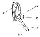
図1〜3を参照して、本発明の好適な実施例は、本体及びその内部に収納される作業モジュールを含む電子鼾防止具において、前記本体1がユーザーの耳介にかけられるための耳掛け11、及び耳孔に入れられるための耳栓12を含み、前記耳掛け11と耳栓12とが一体としてつながり、前記作業モジュール2が前記耳掛け11と耳栓12による内腔の中に位置する電子鼾防止具である。図3を参照して、前記作業モジュール2は、鼾音収集回路21、マイクロプロセッサMCUを中心とする制御回路22、警告注意回路23及び給電回路24を含む。前記鼾音収集回路21及び警告注意回路23はそれぞれ制御回路22に電気的に接続され、前記給電回路24はそれぞれ鼾音収集回路21、制御回路22及び警告注意回路23に低圧直流電力を供給する。前記鼾音収集回路21はその拡声器MIC及び振動センサが採集した、ユーザーが睡眠中に発生させる音声や頭部の振動信号を処理した後で、それぞれ制御回路22に送信する。前記制御回路22はその受信した音声や振動信号が各々の閾値に達したと判定した場合に、鼾音を抑制するため、制御信号を前記耳栓12内に位置する警告注意回路23に送信して、ユーザーを起こさせない程度の音声、震動又は電極による刺激信号を発生させる。 Referring to FIGS. 1 to 3, a preferred embodiment of the present invention is an electronic hook preventing device including a main body and a work module housed therein, and an ear hook for the
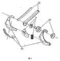
図2を参照して、本実施例において、本体1に、一端が耳栓12に連通され、他端がユーザーの鼻口へ指される鼾音収集パイプ13が更に設けられる。前記鼾音収集回路21の拡声器MICは鼾音収集パイプ13内に位置する。これにより、人が寝る場合に発する鼾音を近距離で精確に収集することができる。 With reference to FIG. 2, in the present embodiment, the
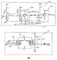
図4を参照して、前記鼾音収集回路21は前記拡声器MICを中心とする音声採集回路210及び前記振動センサを中心とする振動採集回路211を含む。前記音声採集回路210は第1、第2の低周波フィルタ回路2101、2102及び第1の演算増幅回路2103を含み、前記拡声器MICは収集した音声を電気信号に変換して、第1の低周波フィルタ回路2101に送信してフィルタリングを行った後で第1の演算増幅回路2103に送信して増幅処理を行い、更に第2の低周波フィルタ回路2102に送信してフィルタリングを行った後で制御回路22に送信する。前記振動センサは、3軸加速度センサ集積回路U12であり、前記振動採集回路211の3軸加速度センサ集積回路U12は感知した振動信号を電気信号に変換して前記制御回路22に送信する。前記制御回路22は、その受信した音声や振動が各々の閾値に達するかを判定し、またユーザーが鼾をかく状態にあるかを判定する。1分間に60dBの音声が3回以上となると共に、振動が設定したある閾値に達すると、鼾音として確認する。より良い効果を達するために、本実施例の音声採集回路210に第2の演算増幅回路2104が更に設けられる必要がある。つまり、第2の低周波フィルタ回路2102によりフィルタリングされた電気信号は、制御回路22に保存された鼾音経験値と比較されて、ユーザーの鼾音であるかが判定されるように、制御回路22に送信されるだけではなく、前記第2の演算増幅回路2104にも送信されて増幅され、更に前記制御回路22に送信される。前記経験値は、予めユーザーの鼾音を録音し分析することで得られる。 Referring to FIG. 4, the stuttering collecting
図5を参照して、本実施例における制御回路22は、マイクロプロセッサ集積回路U4を中心として構成される。マイクロプロセッサ集積回路U4は、鼾音収集回路21から送信された音声や振動信号を分析して鼾をかいていると確認すると、警告信号を注意回路23に送信して、鼾をかく者に刺激を与える。警告モデルには、音声警告、震動警告、電極刺激警告がある。本実施例において、警告は、昇順で4つのレベルに分けられ、鼾音が停止するまで、3つの鼾音毎に1つのレベルが増える。 Referring to FIG. 5, the
図6を参照して、本実施例において、警告注意回路23は、それぞれ前記制御回路22に電気的に接続される音声刺激回路231、震動刺激回路231及び電極刺激回路231を含む。制御回路22はパルス信号を伝送して、前記音声刺激回路231のスピーカーBL1、震動刺激回路231の震動電動機T1又は電極刺激回路231の電撃シートP1を、音声、震動又は電極による刺激信号を発生させるように誘発する。制御回路22は、その伝送するパルス信号の幅に基づいて音声、震動及び電極の刺激強度を変える。本実施例における、警告注意の刺激信号モデルでは、音声、震動及び電極の順序に従って順次、刺激を与える。 With reference to FIG. 6, in this embodiment, the
図7を参照して、本実施例において、給電回路24は、リチウムイオン電池DC及び電池充電回路240を含む。前記電池充電回路240の中に、USB規格に適合したコネクタが配置される。外部給電源は、リチウムイオン電池DCを充電するように、このコネクタを介して前記リチウムイオン電池充回路に給電する。その同時に、前記USB規格によるコネクタも、外部とのデータ交換インタフェースとして、制御回路22と電気的に接続される。 With reference to FIG. 7, in this embodiment, the
図8を参照して、本実施例の作業モジュール2には、作業状態表示回路25が更に設けられる。この回路は複数のダイオードからなり、前記電子鼾防止具の各種の作業状態を表示することに用いられる。 Referring to FIG. 8, the
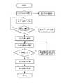
図9を参照して、本実施例の電子鼾防止具の作業フローは、
前記作業モジュール2が、ユーザーが睡眠中に発生させる音声やその頭部の振動を採集する工程Aと、
前記作業モジュール2が、採集した音声が音声閾値以上であり、採集した振動も振動閾値以上であると判定した場合に、ユーザーを起こさせない程度の刺激音声、震動又は電極刺激信号モデルの1つを発生させ、耳栓12を通してユーザーに刺激を与えると共に、鼾音の回数、鼾音のデータ及び/又は振動データを一度記録する工程Bと、
前記作業モジュール2が、ユーザーが睡眠中に発生させる音声及びその頭部の振動を再び採集し、採集した音声が依然として音声閾値以上であり、採集した振動も振動閾値に達すると判定した場合に、元の刺激信号モデルのレベルを向上させ、又は刺激信号モデルを変更し、採集した音声が予め設定した音声閾値より小さく又は採集した振動が振動閾値より小さいと判定した場合に、工程Aに戻して、鼾声防止回数として一度記録する工程Cと、
を備える。With reference to FIG. 9, the work flow of the electronic flaw prevention device of the present embodiment is as follows.
Step A in which the
If the
When the
Is provided.
本実施例において、実施回路の主要な部品は、下記の通りである。 In this embodiment, the main parts of the implementation circuit are as follows.

本実施例の電子鼾防止具は、使用時に耳に置かれるので、鼾音収集回路が人体の鼾音の音源である口腔・鼻腔に近く、人が寝る場合に発する鼾音を精確に収集することができる。電子鼾防止具は、先進的なデジタル音声モデル識別技術の適用に合わせて、音声採集回路、及び3軸加速度センサを中心とする振動採集回路によってリアルタイムに測定しており、刺激や干渉の実施基礎を固めると共に、刺激効果の測定の頼りになる根拠を提供する。患者が鼾をかいていると正確に判断すると、制御回路は、鼾モデルに刺激信号を送信し、患者に異なる強度の刺激を与えるように作動部分を刺激し、また、患者の睡眠が正常になり、鼾音が消えるまで、マイクやセンサによって更に収集される鼾防止効果のフィードバックを記録する。 Since the electronic stutter prevention device of this embodiment is placed on the ear during use, the stuttering collecting circuit is close to the oral cavity / nasal cavity, which is the sound source of the stuttering of the human body, and accurately collects the stuttering that occurs when a person sleeps. be able to. The electronic flaw prevention device measures in real time with a voice collection circuit and a vibration collection circuit centered on a three-axis acceleration sensor in accordance with the application of advanced digital voice model identification technology. And provide a basis on which to measure stimulus effects. When it is accurately determined that the patient is wrinkled, the control circuit sends a stimulus signal to the wrinkle model, stimulates the working part to give the patient different stimuli, and the patient's sleep is normal. Until the noise disappears, the feedback of the anti-fogging effect further collected by the microphone or sensor is recorded.
本発明の技術案を採用すれば、医者が患者のいびきを診断する場合の参考として、ユーザーの鼾音の回数、鼾音の強弱及び密度を記録し、患者の治療方針の判定にとって正確且つ科学的な根拠を提供することができる。
(付記)
(付記1)
本体(1)及びその内部に収納される作業モジュール(2)を含む電子鼾防止具において、
前記本体(1)は、ユーザーの耳介にかけられるための耳掛け(11)及び耳孔に入れられるための耳栓(12)を含み、前記耳掛け(11)と前記耳栓(12)とは一体としてつながり、前記作業モジュール(2)は前記耳掛け(11)と前記耳栓(12)による内腔の中に位置し、
前記作業モジュール(2)は、鼾音収集回路(21)、マイクロプロセッサMCUを中心とする制御回路(22)、警告注意回路(23)及び給電回路(24)を含み、前記鼾音収集回路(21)及び前記警告注意回路(23)のそれぞれが前記制御回路(22)に電気的に接続され、前記給電回路(24)は前記鼾音収集回路(21)、前記制御回路(22)及び前記警告注意回路(23)のそれぞれに低圧直流電力を供給し、前記鼾音収集回路(21)はその拡声器MIC及び振動センサが採集した、ユーザーが睡眠中に発生させる音声や頭部の振動信号を処理した後で、それぞれを前記制御回路(22)に送信し、前記制御回路(22)はその受信した音声や振動信号が各々の閾値に達したと判定した場合に、鼾音を抑制するため、制御信号を前記耳栓(12)内に位置する前記警告注意回路(23)に送信して、ユーザーを起こさせない程度の音声、震動又は電極による刺激信号を発生させることを特徴とする電子鼾防止具。
(付記2)
一端が耳栓(12)に連通され、他端がユーザーの鼻口へ指される鼾音収集パイプ(13)を更に含み、前記拡声器MICは前記鼾音収集パイプ(13)内に位置することを特徴とする付記1に記載の電子鼾防止具。
(付記3)
前記鼾音収集回路(21)は前記拡声器MICを中心とする音声採集回路(210)及び前記振動センサを中心とする振動採集回路(211)を含み、
前記音声採集回路(210)は第1、第2の低周波フィルタ回路(2101、2102)及び第1の演算増幅回路(2013)を含み、前記拡声器MICは収集した音声を電気信号に変換し、前記第1の低周波フィルタ回路(2101)に送信してフィルタリングを行った後で前記第1の演算増幅回路(2013)に送信して増幅処理を行い、更に前記第2の低周波フィルタ回路(2102)に送信してフィルタリングを行った後で前記制御回路(22)に送信し、
前記振動センサは3軸加速度センサ集積回路U12であり、前記振動採集回路(211)の前記3軸加速度センサ集積回路U12は感知した振動信号を電気信号に変換して前記制御回路(22)に送信することを特徴とする付記1に記載の電子鼾防止具。
(付記4)
前記警告注意回路(23)は、前記制御回路(22)に電気的にそれぞれ接続される音声刺激回路(231)、震動刺激回路(232)及び電極刺激回路(233)を含み、前記制御回路(22)はパルス信号を伝送して、前記音声刺激回路(231)のスピーカーBL1、前記震動刺激回路(232)の震動電動機T1又は前記電極刺激回路(233)の電撃シートP1を、音声、震動又は電極による刺激信号を発生させるように誘発することを特徴とする付記1に記載の電子鼾防止具。
(付記5)
前記音声採集回路(210)は第2の演算増幅回路(2104)を更に含み、前記第2の低周波フィルタ回路(2102)によりフィルタリングされた電気信号は、前記制御回路(22)に送信されるだけではなく、前記第2の演算増幅回路(2014)にも送信されて増幅された後に、更に前記制御回路(22)に送信されることを特徴とする付記3に記載の電子鼾防止具。
(付記6)
本体(1)及びその内部に収納される作業モジュール(2)を含み、前記本体(1)にユーザーの耳介にかけられるための耳掛け(11)及びユーザーの耳孔に入れることが可能な耳栓(12)が設けられる電子鼾防止具の鼾防止方法であって、
前記作業モジュール(2)が、ユーザーの睡眠中に発生させる音声やその頭部の振動を採集する工程Aと、
前記作業モジュール(2)が、採集した音声が音声閾値以上であり、採集した振動も振動閾値以上であると判定した場合に、ユーザーを起こさせない程度の刺激音声、震動又は電極刺激信号モデルの1つを発生させ、前記耳栓(12)を通してユーザーに刺激を与える工程Bと、
前記作業モジュール(2)が、ユーザーが睡眠中に発生させる音声及びその頭部の振動を再び採集し、採集した音声が依然として音声閾値以上であり、採集した振動が振動閾値に達したと判定した場合に、元の刺激信号モデルの強度を向上させ、又は刺激信号モデルを変更し、採集した音声が予め設定した音声閾値より小さく又は採集した振動が振動閾値より小さいと判定した場合に、前記工程Aに戻す工程Cと、
を備える電子鼾防止具の鼾防止方法。
(付記7)
前記作業モジュール(2)が、採集した音声が前記音声閾値以上であり、採集した振動も前記振動閾値以上であると判定した場合に、鼾音の回数、鼾音のデータ及び/又は振動データを一度記録することを更に備えることを特徴とする付記6に記載の鼾防止方法。
(付記8)
前記作業モジュール(2)が、採集した音声が前記音声閾値より小さく、又は採集した振動が前記振動閾値より小さい場合に、鼾声防止回数として一度記録することを更に備えることを特徴とする付記6に記載の鼾防止方法。
(付記9)
前記音声閾値は、1分間に60dBが3回以上となるように設定され、又は予めユーザーの鼾音を録音し分析することで得られた経験値に設定されることを特徴とする付記6に記載の鼾防止方法。
(付記10)
前記作業モジュール(2)は、鼾音収集回路(21)、マイクロプロセッサU2を中心とする制御回路(22)、警告注意回路(23)及び給電回路(24)を含み、前記鼾音収集回路(21)及び前記警告注意回路(23)のそれぞれが前記制御回路(22)に電気的に接続され、前記給電回路(24)が前記鼾音収集回路(21)、前記制御回路(22)及び前記警告注意回路(23)のそれぞれに給電し、前記鼾音収集回路(21)がその拡声器MIC及び振動センサによって、ユーザーが睡眠中に発生させる音声や頭部の振動信号を採集することを特徴とする付記6に記載の鼾防止方法。
(付記11)
一端が耳栓(12)に連通され、他端がユーザーの鼻口へ指される鼾音収集パイプ(13)を設けることを更に備え、少なくとも前記作業モジュール(2)の拡声器MICが前記鼾音収集パイプ(13)内に置かれ、ユーザーが睡眠中に発する音声を近距離で収集するようになる付記6に記載の鼾防止方法。
(付記12)
前記鼾音収集回路(21)は、前記拡声器MICを中心とする音声採集回路(210)及び前記振動センサを中心とする振動採集回路(211)を含み、
前記音声採集回路(210)は、第1、第2の低周波フィルタ回路(2101、2102)及び第1の演算増幅回路(2103)を含み、前記拡声器MICは収集した音声を電気信号に変換し、前記第1の低周波フィルタ回路(2101)に送信してフィルタリングを行った後で前記第1の演算増幅回路(2103)に送信して増幅処理を行い、更に前記第2の低周波フィルタ回路(2102)に送信してフィルタリングを行った後で前記制御回路(22)に送信し、
前記振動センサは、3軸加速度センサ集積回路U12であり、前記振動採集回路(211)の前記3軸加速度センサ集積回路U12は感知した振動信号を電気信号に変換して前記制御回路(22)に送信することを特徴とする付記10に記載の鼾防止方法。If the technical solution of the present invention is adopted, the number of stuttering of a user, the strength and density of stuttering, and the density are recorded as a reference when a doctor diagnoses a patient's snoring, and it is accurate and scientific for judgment of a patient's treatment policy Can provide a rationale.
(Appendix)
(Appendix 1)
In the electronic flaw prevention device including the main body (1) and the work module (2) housed therein,
The main body (1) includes an ear hook (11) to be put on a user's pinna and an ear plug (12) to be put in an ear hole, and the ear hook (11) and the ear plug (12) are Connected together, the working module (2) is located in the lumen by the ear hook (11) and the earplug (12),
The work module (2) includes a noise collecting circuit (21), a control circuit (22) centered on a microprocessor MCU, a warning attention circuit (23), and a power feeding circuit (24). 21) and the warning attention circuit (23) are electrically connected to the control circuit (22), and the power feeding circuit (24) is connected to the noise collecting circuit (21), the control circuit (22) and the Low-voltage DC power is supplied to each of the warning and attention circuits (23), and the sound collection circuit (21) collects the sound and head vibration signals generated by the user during sleep, which are collected by the loudspeaker MIC and the vibration sensor. Are transmitted to the control circuit (22), and the control circuit (22) suppresses stuttering when it determines that the received voice or vibration signal has reached each threshold value. Because of the system Electronic wrinkle prevention device characterized in that a signal is transmitted to the warning attention circuit (23) located in the earplug (12) to generate a sound signal, vibration, or stimulation signal by electrodes that does not wake up the user .
(Appendix 2)
It further includes a stuttering collection pipe (13) with one end communicating with the ear plug (12) and the other end pointing to the user's nostril, wherein the loudspeaker MIC is located within the stuttering collection pipe (13). The electronic flaw prevention device according to
(Appendix 3)
The stuttering collecting circuit (21) includes a voice collecting circuit (210) centered on the loudspeaker MIC and a vibration collecting circuit (211) centered on the vibration sensor,
The voice collecting circuit (210) includes first and second low frequency filter circuits (2101, 2102) and a first operational amplifier circuit (2013), and the loudspeaker MIC converts the collected voice into an electrical signal. The first low-frequency filter circuit (2101) is transmitted and filtered, and then transmitted to the first operational amplifier circuit (2013) for amplification processing, and further the second low-frequency filter circuit (2102) is sent to the control circuit (22) after filtering,
The vibration sensor is a triaxial acceleration sensor integrated circuit U12, and the triaxial acceleration sensor integrated circuit U12 of the vibration collecting circuit (211) converts the sensed vibration signal into an electric signal and transmits it to the control circuit (22). The electronic flaw prevention device according to
(Appendix 4)
The warning attention circuit (23) includes a voice stimulation circuit (231), a vibration stimulation circuit (232), and an electrode stimulation circuit (233) electrically connected to the control circuit (22), respectively. 22) transmits a pulse signal to transmit the sound BL, the vibration BL, the speaker BL1 of the voice stimulation circuit (231), the vibration motor T1 of the vibration stimulation circuit (232), or the electric shock sheet P1 of the electrode stimulation circuit (233). The electronic flaw prevention device according to
(Appendix 5)
The voice collecting circuit (210) further includes a second operational amplifier circuit (2104), and the electrical signal filtered by the second low frequency filter circuit (2102) is transmitted to the control circuit (22). The electronic flaw prevention device according to
(Appendix 6)
An earplug that includes a main body (1) and a work module (2) housed in the main body (1) and that can be put into the user's auricle (11) and an earplug that can be put into the user's ear canal (12) is a method for preventing wrinkles of an electronic wrinkle prevention device,
Step A in which the work module (2) collects sound generated during the user's sleep and vibration of the head;
When the work module (2) determines that the collected voice is equal to or higher than the voice threshold value and the collected vibration is equal to or higher than the vibration threshold value, 1 of the stimulus voice, vibration or electrode stimulus signal model that does not cause the user to wake up. Generating step B and stimulating the user through the earplug (12);
The work module (2) collects the voice generated by the user during sleep and the vibration of the head again, and determines that the collected voice is still above the voice threshold and the collected vibration has reached the vibration threshold. In the case where the intensity of the original stimulus signal model is improved or the stimulus signal model is changed, and it is determined that the collected voice is smaller than a preset voice threshold or the collected vibration is smaller than the vibration threshold, the step Step C to return to A,
A method for preventing wrinkles of an electronic wrinkle prevention device comprising:
(Appendix 7)
When the work module (2) determines that the collected voice is equal to or higher than the voice threshold value and the collected vibration is equal to or higher than the vibration threshold value, the number of noises, the noise data and / or the vibration data are obtained. The wrinkle prevention method according to
(Appendix 8)
The
(Appendix 9)
(Appendix 10)
The work module (2) includes a noise collecting circuit (21), a control circuit (22) centering on the microprocessor U2, a warning attention circuit (23), and a power feeding circuit (24). 21) and the warning attention circuit (23) are electrically connected to the control circuit (22), and the power feeding circuit (24) is connected to the noise collecting circuit (21), the control circuit (22), and the Power is supplied to each of the warning attention circuit (23), and the sound collecting circuit (21) collects a voice generated by the user during sleep and a vibration signal of the head by the loudspeaker MIC and the vibration sensor. The wrinkle prevention method according to
(Appendix 11)
It further comprises providing a sound collecting pipe (13) having one end communicating with the ear plug (12) and the other end pointing to the user's nostril, and at least the loudspeaker MIC of the work module (2) The wrinkle prevention method according to
(Appendix 12)
The stuttering collecting circuit (21) includes a voice collecting circuit (210) centered on the loudspeaker MIC and a vibration collecting circuit (211) centered on the vibration sensor,
The voice collecting circuit (210) includes first and second low frequency filter circuits (2101, 2102) and a first operational amplifier circuit (2103), and the loudspeaker MIC converts the collected voice into an electrical signal. Then, after transmitting to the first low-frequency filter circuit (2101) and performing filtering, it transmits to the first operational amplifier circuit (2103) to perform amplification processing, and further, the second low-frequency filter circuit Sent to the circuit (2102), filtered and sent to the control circuit (22),
The vibration sensor is a triaxial acceleration sensor integrated circuit U12, and the triaxial acceleration sensor integrated circuit U12 of the vibration collecting circuit (211) converts the sensed vibration signal into an electric signal and sends it to the control circuit (22). The method of preventing wrinkles according to supplementary note 10, wherein transmission is performed.
Claims (10)
Translated fromJapanese前記本体(1)は、ユーザーの耳介にかけられるための耳掛け(11)及び耳孔に入れられるための耳栓(12)を含み、前記耳掛け(11)と前記耳栓(12)とは一体としてつながり、前記作業モジュール(2)は前記耳掛け(11)と前記耳栓(12)による内腔の中に位置し、
前記作業モジュール(2)は、鼾音収集回路(21)、マイクロプロセッサMCUを中心とする制御回路(22)、警告注意回路(23)及び給電回路(24)を含み、前記鼾音収集回路(21)及び前記警告注意回路(23)のそれぞれが前記制御回路(22)に電気的に接続され、前記給電回路(24)は前記鼾音収集回路(21)、前記制御回路(22)及び前記警告注意回路(23)のそれぞれに低圧直流電力を供給し、前記鼾音収集回路(21)はその拡声器MIC及び振動センサが採集した、ユーザーが睡眠中に発生させる音声や頭部の振動信号を処理した後で、それぞれを前記制御回路(22)に送信し、前記制御回路(22)はその受信した音声や振動信号が各々の閾値に達したと判定した場合に、鼾音を抑制するため、制御信号を前記耳栓(12)内に位置する前記警告注意回路(23)に送信して、ユーザーを起こさせない程度の音声、震動又は電極による刺激信号を発生させ、
一端が前記耳栓(12)に連通され、他端がユーザーの鼻口へ指される鼾音収集パイプ(13)を更に含み、前記拡声器MICは前記鼾音収集パイプ(13)内に位置することを特徴とする電子鼾防止具。In the electronic flaw prevention device including the main body (1) and the work module (2) housed therein,
The main body (1) includes an ear hook (11) to be put on a user's pinna and an ear plug (12) to be put in an ear hole, and the ear hook (11) and the ear plug (12) are Connected together, the working module (2) is located in the lumen by the ear hook (11) and the earplug (12),
The work module (2) includes a noise collecting circuit (21), a control circuit (22) centered on a microprocessor MCU, a warning attention circuit (23), and a power feeding circuit (24). 21) and the warning attention circuit (23) are electrically connected to the control circuit (22), and the power feeding circuit (24) is connected to the noise collecting circuit (21), the control circuit (22) and the Low-voltage DC power is supplied to each of the warning and attention circuits (23), and the sound collection circuit (21) collects the sound and head vibration signals generated by the user during sleep, which are collected by the loudspeaker MIC and the vibration sensor. Are transmitted to the control circuit (22), and the control circuit (22) suppresses stuttering when it determines that the received voice or vibration signal has reached each threshold value. Because of the system Signals are transmitted to the warning note circuit (23) located in said ear plugs (12), so as not to cause a user voice, to generate a stimulation signal by the vibration or the electrode,
One end communicates withsaid earplug (12), the other end further comprises a Ibikion collecting pipe pointed to the user's nose and mouth (13), said loudspeaker MIC is located in the Ibikion collecting pipe (13)you whereinelectronic snoring preventer to be.
前記音声採集回路(210)は第1、第2の低周波フィルタ回路(2101、2102)及び第1の演算増幅回路(2013)を含み、前記拡声器MICは収集した音声を電気信号に変換し、前記第1の低周波フィルタ回路(2101)に送信してフィルタリングを行った後で前記第1の演算増幅回路(2013)に送信して増幅処理を行い、更に前記第2の低周波フィルタ回路(2102)に送信してフィルタリングを行った後で前記制御回路(22)に送信し、
前記振動センサは3軸加速度センサ集積回路U12であり、前記振動採集回路(211)の前記3軸加速度センサ集積回路U12は感知した振動信号を電気信号に変換して前記制御回路(22)に送信することを特徴とする請求項1に記載の電子鼾防止具。The stuttering collecting circuit (21) includes a voice collecting circuit (210) centered on the loudspeaker MIC and a vibration collecting circuit (211) centered on the vibration sensor,
The voice collecting circuit (210) includes first and second low frequency filter circuits (2101, 2102) and a first operational amplifier circuit (2013), and the loudspeaker MIC converts the collected voice into an electrical signal. The first low-frequency filter circuit (2101) is transmitted and filtered, and then transmitted to the first operational amplifier circuit (2013) for amplification processing, and further the second low-frequency filter circuit (2102) is sent to the control circuit (22) after filtering,
The vibration sensor is a triaxial acceleration sensor integrated circuit U12, and the triaxial acceleration sensor integrated circuit U12 of the vibration collecting circuit (211) converts the sensed vibration signal into an electric signal and transmits it to the control circuit (22). The electronic flaw prevention device according to claim 1, wherein
前記作業モジュール(2)が、ユーザーが睡眠中に発生させる音声やその頭部の振動を採集する工程Aと、
前記作業モジュール(2)が、採集した音声が音声閾値以上であり、採集した振動も振動閾値以上であると判定した場合に、ユーザーを起こさせない程度の刺激音声、震動又は電極刺激信号モデルの1つを発生させ、前記耳栓(12)を通してユーザーに刺激を与える工程Bと、
前記作業モジュール(2)が、ユーザーが睡眠中に発生させる音声及びその頭部の振動を再び採集し、採集した音声が依然として音声閾値以上であり、採集した振動が振動閾値に達したと判定した場合に、元の刺激信号モデルの強度を向上させ、又は刺激信号モデルを変更し、採集した音声が予め設定した音声閾値より小さく又は採集した振動が振動閾値より小さいと判定した場合に、前記工程Aに戻す工程Cと、
を備える電子鼾防止具の鼾防止方法。A main body (1) provided with an ear hook (11) to be put on the user's pinna and an earplug (12) that can be put into the user's ear hole, and an operation stored in the main body (1) a module (2), one end of which communicates withthe on earplug (12)comprises the other endand is Ibikion collecting pipe (13) pointed to the user's nose andmouth, the at least loudspeaker of the work module (2) Anelectronic anti- snoring methodfor anelectronic anti- smoke device in which a device MIC is placed in the sound collecting pipe (13) and collects a sound emitted by a user during sleep at a short distance,
Step A in which the work module (2) collects voice generated by the user during sleep and vibration of the head;
When the work module (2) determines that the collected voice is equal to or higher than the voice threshold value and the collected vibration is equal to or higher than the vibration threshold value, 1 of the stimulus voice, vibration or electrode stimulus signal model that does not cause the user to wake up. Generating step B and stimulating the user through the earplug (12);
The work module (2) collects the voice generated by the user during sleep and the vibration of the head again, and determines that the collected voice is still above the voice threshold and the collected vibration has reached the vibration threshold. In the case where the intensity of the original stimulus signal model is improved or the stimulus signal model is changed, and it is determined that the collected voice is smaller than a preset voice threshold or the collected vibration is smaller than the vibration threshold, the step Step C to return to A,
A method for preventing wrinkles of an electronic wrinkle prevention device comprising:
前記音声採集回路(210)は、第1、第2の低周波フィルタ回路(2101、2102)及び第1の演算増幅回路(2103)を含み、前記拡声器MICは収集した音声を電気信号に変換し、前記第1の低周波フィルタ回路(2101)に送信してフィルタリングを行った後で前記第1の演算増幅回路(2103)に送信して増幅処理を行い、更に前記第2の低周波フィルタ回路(2102)に送信してフィルタリングを行った後で前記制御回路(22)に送信し、
前記振動センサは、3軸加速度センサ集積回路U12であり、前記振動採集回路(211)の前記3軸加速度センサ集積回路U12は感知した振動信号を電気信号に変換して前記制御回路(22)に送信することを特徴とする請求項9に記載の鼾防止方法。The stuttering collecting circuit (21) includes a voice collecting circuit (210) centered on the loudspeaker MIC and a vibration collecting circuit (211) centered on the vibration sensor,
The voice collecting circuit (210) includes first and second low frequency filter circuits (2101, 2102) and a first operational amplifier circuit (2103), and the loudspeaker MIC converts the collected voice into an electrical signal. Then, after transmitting to the first low-frequency filter circuit (2101) and performing filtering, it transmits to the first operational amplifier circuit (2103) to perform amplification processing, and further, the second low-frequency filter circuit Sent to the circuit (2102), filtered and sent to the control circuit (22),
The vibration sensor is a triaxial acceleration sensor integrated circuit U12, and the triaxial acceleration sensor integrated circuit U12 of the vibration collecting circuit (211) converts the sensed vibration signal into an electric signal and sends it to the control circuit (22). The method for preventing wrinkles according to claim9 , wherein transmission is performed.
Applications Claiming Priority (3)
| Application Number | Priority Date | Filing Date | Title |
|---|---|---|---|
| CN201310592276.9 | 2013-11-22 | ||
| CN201310592276.9ACN104323880B (en) | 2013-11-22 | 2013-11-22 | Electronic snore-ceasing device and snore-ceasing method |
| PCT/CN2014/091648WO2015074563A1 (en) | 2013-11-22 | 2014-11-19 | Electronic snore-ceasing device and snore-ceasing method |
Publications (2)
| Publication Number | Publication Date |
|---|---|
| JP2016530033A JP2016530033A (en) | 2016-09-29 |
| JP6134449B2true JP6134449B2 (en) | 2017-05-24 |
Family
ID=52398796
Family Applications (1)
| Application Number | Title | Priority Date | Filing Date |
|---|---|---|---|
| JP2016541803AExpired - Fee RelatedJP6134449B2 (en) | 2013-11-22 | 2014-11-19 | Electronic flaw prevention device and flaw prevention method |
Country Status (5)
| Country | Link |
|---|---|
| US (1) | US10820854B2 (en) |
| EP (1) | EP3072482A4 (en) |
| JP (1) | JP6134449B2 (en) |
| CN (1) | CN104323880B (en) |
| WO (1) | WO2015074563A1 (en) |
Families Citing this family (24)
| Publication number | Priority date | Publication date | Assignee | Title |
|---|---|---|---|---|
| GB201501983D0 (en)* | 2015-02-06 | 2015-03-25 | Morgan Innovation & Technology Ltd | Treatment of snoring and sleep apnoea |
| CN105268079A (en)* | 2015-05-19 | 2016-01-27 | 洛阳德威机电科技有限公司 | Electronic device capable of inhibiting snore |
| CN106473698A (en)* | 2015-08-24 | 2017-03-08 | 深圳市云中飞电子有限公司 | A kind of snore relieving the method and apparatus for monitoring sleep state |
| CN106806047A (en)* | 2015-11-27 | 2017-06-09 | 英业达科技有限公司 | Ear-hang device for preventing snoring and snore relieving system |
| CN106814641A (en)* | 2015-11-27 | 2017-06-09 | 英业达科技有限公司 | Snore stopper control method |
| CN110139596B (en)* | 2016-12-29 | 2023-07-14 | 皇家飞利浦有限公司 | System and method for determining personalized anti-snoring solutions |
| CN106821581B (en)* | 2017-01-23 | 2020-05-15 | 广州逸善舒晨生物科技有限公司 | Non-invasive snore treatment system |
| WO2018201343A1 (en)* | 2017-05-03 | 2018-11-08 | 深圳市云中飞电子有限公司 | Terminal, computer-readable storage medium, electronic snoring-prevention device and snoring-prevention method using same |
| CN208388850U (en)* | 2017-08-28 | 2019-01-18 | 深圳市云中飞电子有限公司 | eyeshade |
| US10957335B2 (en)* | 2017-12-28 | 2021-03-23 | Sleep Number Corporation | Home automation having user privacy protections |
| CN108210153B (en)* | 2018-01-25 | 2023-04-25 | 九江学院 | Intelligent snore relieving device and method |
| CN108451503A (en)* | 2018-03-12 | 2018-08-28 | 卢纪元 | Biofeedback therapy mechanism and intelligent sleep diagnosis and therapy system based on the mechanism |
| US10618522B2 (en)* | 2018-03-27 | 2020-04-14 | Hong Kong Productivity Council (HKPC) | Drowsiness detection and intervention system and method |
| CN108618881A (en)* | 2018-05-10 | 2018-10-09 | 深圳市云中飞电子有限公司 | A kind of snore stopper, snore relieving method and system |
| CN108938174A (en)* | 2018-05-29 | 2018-12-07 | 四川九通慧医药信息科技有限公司 | A kind of anti-snore device and snore relieving method |
| CN110136560B (en)* | 2019-05-31 | 2020-12-29 | 山东交通学院 | Oblique-cut bionic bat ear horn model functional device and experimental method |
| CN110584626A (en)* | 2019-09-04 | 2019-12-20 | 冯学艺 | Head-mounted snore monitoring device and snore stopping method |
| CN111012361A (en)* | 2019-12-31 | 2020-04-17 | 汪宇恒 | Intelligent snoring behavior monitoring device and snoring early warning system |
| EP4138654A4 (en)* | 2020-04-24 | 2024-08-07 | Ta Nooma Ltd. | Systems and methods for snoring detection and prevention |
| CN111866687A (en)* | 2020-06-10 | 2020-10-30 | 苏州海卡缔听力技术有限公司 | Hearing aid system with biological identification function and identification method thereof |
| CN111933181B (en)* | 2020-07-10 | 2022-05-17 | 北京理工大学 | Snore feature extraction and detection method and device based on complex order derivative processing |
| CN112642058A (en)* | 2020-12-30 | 2021-04-13 | 西安慧脑智能科技有限公司 | Multifunctional physiotherapy instrument, multifunctional physiotherapy system and control method |
| CN118303844B (en)* | 2024-04-24 | 2025-04-08 | 深圳疆泰科技有限公司 | Sleep state information processing method and related device |
| CN118502332B (en)* | 2024-07-19 | 2024-10-15 | 山东乐康电子产业研究院有限公司 | Control system based on negative electric field sleep assisting and abnormal snoring detection intervention |
Family Cites Families (27)
| Publication number | Priority date | Publication date | Assignee | Title |
|---|---|---|---|---|
| DE3322571A1 (en)* | 1983-06-23 | 1984-04-05 | Wolfhart 4600 Dortmund Nemitz | Device for impeding and interrupting snoring sounds of an individual |
| US4644330A (en)* | 1983-10-11 | 1987-02-17 | Dowling Anthony R | Anti-snoring device |
| FR2568397B1 (en)* | 1984-07-27 | 1987-08-14 | Mequignon Jean Claude | PROCESS FOR STOPPING THE HUMAN SNORING OF ITS EMISSIONS AND APPARATUS NECESSARY FOR THE IMPLEMENTATION OF THIS PROCESS |
| CN86209835U (en)* | 1986-12-06 | 1987-11-18 | 王天麟 | Snore interrupting device |
| ES2115992T3 (en)* | 1994-02-01 | 1998-07-01 | Alexander Dr Med Balkanyi | DEVICE TO SUPPRESS SNORING. |
| AUPN304895A0 (en)* | 1995-05-19 | 1995-06-15 | Somed Pty Limited | Device for detecting and recording snoring |
| US6314324B1 (en)* | 1999-05-05 | 2001-11-06 | Respironics, Inc. | Vestibular stimulation system and method |
| US20030199945A1 (en)* | 2002-02-11 | 2003-10-23 | James Ciulla | Device and method for treating disordered breathing |
| US7532934B2 (en)* | 2003-09-18 | 2009-05-12 | Cardiac Pacemakers, Inc. | Snoring detection system and method |
| JP3913748B2 (en)* | 2004-03-25 | 2007-05-09 | 三洋電機株式会社 | Snoring detection method and detection apparatus |
| JP2009519802A (en) | 2005-12-20 | 2009-05-21 | コーニンクレッカ フィリップス エレクトロニクス エヌ ヴィ | System and method for reducing snoring and / or sleep apnea in a sleeping person |
| US9779751B2 (en)* | 2005-12-28 | 2017-10-03 | Breath Research, Inc. | Respiratory biofeedback devices, systems, and methods |
| CN101351152A (en)* | 2005-12-28 | 2009-01-21 | 尼伦简·比科 | Respiration biofeedback device |
| US20070239225A1 (en)* | 2006-02-28 | 2007-10-11 | Saringer John H | Training device and method to suppress sounds caused by sleep and breathing disorders |
| EP1991115B1 (en)* | 2006-02-28 | 2013-04-24 | Koninklijke Philips Electronics N.V. | External device that continuously monitors for osdb and delivers audio stimulation therapy |
| US7861723B2 (en)* | 2007-06-07 | 2011-01-04 | David L. Dedrick | Apparatus, system and method for detecting and treating airway obstructive conditions during sleep |
| US8628478B2 (en)* | 2009-02-25 | 2014-01-14 | Empire Technology Development Llc | Microphone for remote health sensing |
| US8579794B2 (en)* | 2008-05-02 | 2013-11-12 | Dymedix Corporation | Agitator to stimulate the central nervous system |
| EP2263620A1 (en)* | 2009-06-16 | 2010-12-22 | Koninklijke Philips Electronics N.V. | Snoring reduction apparatus |
| DE102009036510A1 (en) | 2009-08-07 | 2011-02-10 | Husemann, Britta, Dr. med. | Anti-snoring device |
| CN101785721A (en) | 2010-02-10 | 2010-07-28 | 福州梦想现代科技有限公司 | Snoring reminder |
| US20120212345A1 (en)* | 2011-02-18 | 2012-08-23 | Polly Harman | Device for the treatment of sleep-related conditions |
| AU2012347770A1 (en)* | 2011-12-07 | 2014-06-26 | Otologics, Llc | Sleep apnea control device |
| CN202568578U (en)* | 2012-04-17 | 2012-12-05 | 苏波 | Intelligent ear canal snore preventing device |
| CN202619947U (en) | 2012-06-20 | 2012-12-26 | 北京华奥圣康科技有限公司 | Intelligent snore stopping device |
| US20140276227A1 (en)* | 2013-03-14 | 2014-09-18 | Aliphcom | Sleep management implementing a wearable data-capable device for snoring-related conditions and other sleep disturbances |
| CN203710215U (en) | 2013-11-22 | 2014-07-16 | 罗强 | Electronic snore-ceasing device |
- 2013
- 2013-11-22CNCN201310592276.9Apatent/CN104323880B/enactiveActive
- 2014
- 2014-11-19JPJP2016541803Apatent/JP6134449B2/ennot_activeExpired - Fee Related
- 2014-11-19USUS15/033,971patent/US10820854B2/ennot_activeExpired - Fee Related
- 2014-11-19EPEP14864945.2Apatent/EP3072482A4/ennot_activeWithdrawn
- 2014-11-19WOPCT/CN2014/091648patent/WO2015074563A1/enactiveApplication Filing
Also Published As
| Publication number | Publication date |
|---|---|
| CN104323880B (en) | 2017-02-08 |
| US10820854B2 (en) | 2020-11-03 |
| US20160270720A1 (en) | 2016-09-22 |
| WO2015074563A1 (en) | 2015-05-28 |
| JP2016530033A (en) | 2016-09-29 |
| EP3072482A4 (en) | 2017-12-13 |
| EP3072482A1 (en) | 2016-09-28 |
| CN104323880A (en) | 2015-02-04 |
Similar Documents
| Publication | Publication Date | Title |
|---|---|---|
| JP6134449B2 (en) | Electronic flaw prevention device and flaw prevention method | |
| JP6618482B2 (en) | Automatic detection of tooth clenching and / or tooth grinding | |
| US11297444B2 (en) | Hearing aid system | |
| EP3654830B1 (en) | Earphones for measuring and entraining respiration | |
| US20150164361A1 (en) | Sound stimulator for memory enhancement | |
| CN101340869A (en) | System and method for reducing snoring and/or sleep apnea of sleeping person | |
| CN111698940A (en) | Measuring respiration with an in-the-ear accelerometer | |
| CN213426407U (en) | Bone conduction speaker and bone conduction earphone with wearing detection function | |
| CN110891477A (en) | Earphone for measuring and entraining respiration | |
| US20170035350A1 (en) | System and method for detecting bruxism | |
| CN110368005A (en) | A kind of intelligent earphone and mood and physiological health monitoring method based on intelligent earphone | |
| CN106333673B (en) | Hypnosis depth detector | |
| WO2019214337A1 (en) | Snore-ceasing equipment, and method and system for ceasing snoring | |
| US20230238127A1 (en) | Medical device control with verification bypass | |
| JP2007236534A (en) | Method and system for obtaining an RR interval index | |
| CN203710215U (en) | Electronic snore-ceasing device | |
| CN208892623U (en) | A kind of modified form pet stethoscope | |
| WO2020013098A1 (en) | Physiological state evaluation device | |
| CN107348945B (en) | A non-recording sleep talking and snoring monitoring system and method | |
| CN212115637U (en) | Device for automatically taking earplugs in sleep | |
| CN203710544U (en) | A biofeedback headache treatment instrument | |
| CN205107675U (en) | Judge whether tired device of brain | |
| WO2018201343A1 (en) | Terminal, computer-readable storage medium, electronic snoring-prevention device and snoring-prevention method using same | |
| CN112472121A (en) | In-ear objective tinnitus diagnosis device | |
| WO2020089856A1 (en) | Physiological measurement management utilizing prosthesis technology and/or other technology |
Legal Events
| Date | Code | Title | Description |
|---|---|---|---|
| A621 | Written request for application examination | Free format text:JAPANESE INTERMEDIATE CODE: A621 Effective date:20160314 | |
| A131 | Notification of reasons for refusal | Free format text:JAPANESE INTERMEDIATE CODE: A131 Effective date:20170117 | |
| A977 | Report on retrieval | Free format text:JAPANESE INTERMEDIATE CODE: A971007 Effective date:20170120 | |
| A521 | Request for written amendment filed | Free format text:JAPANESE INTERMEDIATE CODE: A523 Effective date:20170315 | |
| TRDD | Decision of grant or rejection written | ||
| A01 | Written decision to grant a patent or to grant a registration (utility model) | Free format text:JAPANESE INTERMEDIATE CODE: A01 Effective date:20170328 | |
| A61 | First payment of annual fees (during grant procedure) | Free format text:JAPANESE INTERMEDIATE CODE: A61 Effective date:20170421 | |
| R150 | Certificate of patent or registration of utility model | Ref document number:6134449 Country of ref document:JP Free format text:JAPANESE INTERMEDIATE CODE: R150 | |
| R250 | Receipt of annual fees | Free format text:JAPANESE INTERMEDIATE CODE: R250 | |
| R250 | Receipt of annual fees | Free format text:JAPANESE INTERMEDIATE CODE: R250 | |
| R250 | Receipt of annual fees | Free format text:JAPANESE INTERMEDIATE CODE: R250 | |
| R250 | Receipt of annual fees | Free format text:JAPANESE INTERMEDIATE CODE: R250 | |
| LAPS | Cancellation because of no payment of annual fees |