JP6133541B2 - Mirror device for vehicle - Google Patents
Mirror device for vehicleDownload PDFInfo
- Publication number
- JP6133541B2 JP6133541B2JP2012028778AJP2012028778AJP6133541B2JP 6133541 B2JP6133541 B2JP 6133541B2JP 2012028778 AJP2012028778 AJP 2012028778AJP 2012028778 AJP2012028778 AJP 2012028778AJP 6133541 B2JP6133541 B2JP 6133541B2
- Authority
- JP
- Japan
- Prior art keywords
- vehicle
- circumferential direction
- mirror
- sliding
- arrangement surface
- Prior art date
- Legal status (The legal status is an assumption and is not a legal conclusion. Google has not performed a legal analysis and makes no representation as to the accuracy of the status listed.)
- Active
Links
- 230000007423decreaseEffects0.000claimsdescription4
- 230000002093peripheral effectEffects0.000description17
- 210000000078clawAnatomy0.000description8
- 239000000314lubricantSubstances0.000description3
- 238000005299abrasionMethods0.000description2
- 238000000926separation methodMethods0.000description2
- 238000013459approachMethods0.000description1
- 238000007599dischargingMethods0.000description1
- 239000000428dustSubstances0.000description1
- 239000004519greaseSubstances0.000description1
- 230000005764inhibitory processEffects0.000description1
- 238000012986modificationMethods0.000description1
- 230000004048modificationEffects0.000description1
- 239000004576sandSubstances0.000description1
- 230000011218segmentationEffects0.000description1
Images


Classifications
- G—PHYSICS
- G02—OPTICS
- G02B—OPTICAL ELEMENTS, SYSTEMS OR APPARATUS
- G02B7/00—Mountings, adjusting means, or light-tight connections, for optical elements
- G02B7/18—Mountings, adjusting means, or light-tight connections, for optical elements for prisms; for mirrors
- G02B7/182—Mountings, adjusting means, or light-tight connections, for optical elements for prisms; for mirrors for mirrors
- B—PERFORMING OPERATIONS; TRANSPORTING
- B60—VEHICLES IN GENERAL
- B60R—VEHICLES, VEHICLE FITTINGS, OR VEHICLE PARTS, NOT OTHERWISE PROVIDED FOR
- B60R1/00—Optical viewing arrangements; Real-time viewing arrangements for drivers or passengers using optical image capturing systems, e.g. cameras or video systems specially adapted for use in or on vehicles
- B60R1/02—Rear-view mirror arrangements
- B60R1/06—Rear-view mirror arrangements mounted on vehicle exterior
Landscapes
- Engineering & Computer Science (AREA)
- Physics & Mathematics (AREA)
- Multimedia (AREA)
- Mechanical Engineering (AREA)
- General Physics & Mathematics (AREA)
- Optics & Photonics (AREA)
- Rear-View Mirror Devices That Are Mounted On The Exterior Of The Vehicle (AREA)
Description
Translated fromJapanese本発明は、ミラーが保持される回動部材が回動されてミラーの鏡面角度が調整される車両用ミラー装置に関する。 The present invention relates to a vehicle mirror device in which a rotating member that holds a mirror is rotated to adjust a mirror surface angle of the mirror.
下記特許文献1に記載された鏡面角度調整装置では、ミラーがミラーホルダに保持されると共に、ミラーホルダがケースに回動可能に保持されている。これにより、ミラーホルダが回動されることで、ミラーの鏡面角度が調整される。 In the mirror surface angle adjusting device described in
さらに、ミラーホルダに摺動部が設けられると共に、ケースに回動面が設けられており、ミラーホルダが回動される際には、摺動部が回動面を摺動される。 Further, the mirror holder is provided with a sliding portion, and the case is provided with a rotating surface. When the mirror holder is rotated, the sliding portion is slid on the rotating surface.
ここで、このような鏡面角度調整装置では、仮に摺動部や回動面に異物が付着した場合でも、摺動部と回動面との間から異物を効果的に排出できるのが好ましい。 Here, in such a mirror surface angle adjusting device, it is preferable that the foreign matter can be effectively discharged from between the sliding portion and the rotating surface even if the foreign matter adheres to the sliding portion or the rotating surface.
本発明は、上記事実を考慮し、摺動部と突出部との間から異物を効果的に排出できる車両用ミラー装置を得ることが目的である。 In view of the above fact, an object of the present invention is to obtain a vehicle mirror device capable of effectively discharging foreign matter from between a sliding portion and a protruding portion.
請求項1に記載の車両用ミラー装置は、車両に設けられるミラーと、前記ミラーが保持される回動部材と、前記回動部材が回動可能に保持されると共に、配置面が設けられ、前記回動部材が前記配置面に沿って回動されて前記ミラーの鏡面角度が調整される保持部材と、前記回動部材及び前記保持部材の一方に設けられた摺動部と、前記回動部材及び前記保持部材の他方に突出して設けられて摺動部分が設けられると共に、前記配置面の中心軸周りの周方向である前記配置面の横周方向に対し前記回動部材の回動中心を中心としかつ前記配置面の中心軸を通過する周方向である前記配置面の縦周方向側に向けられて延在され、かつ、前記配置面の縦周方向において分割されて一方の分割部位と他方の分割部位とが前記配置面の横周方向において離間されると共に前記摺動部分を前記配置面の縦周方向において重複配置され、前記回動部材が回動される際に前記摺動部が前記摺動部分を摺動する突出部と、を備えている。Vehicle mirror device according to
請求項2に記載の車両用ミラー装置は、請求項1に記載の車両用ミラー装置において、前記摺動部が摺動する前記突出部の摺動部分を面状にしている。 According to a second aspect of the present invention, in the vehicle mirror device according to the first aspect, the sliding portion of the protruding portion on which the sliding portion slides is formed into a planar shape.
請求項3に記載の車両用ミラー装置は、請求項1又は請求項2に記載の車両用ミラー装置において、前記突出部を前記配置面の縦周方向に対し前記配置面の横周方向側に向けて配置している。A vehicle mirror device according to a third aspect is the vehicle mirror device according to the first or secondaspect , wherein the protruding portion isdisposed on a lateral direction side of thearrangement surface withrespect toa longitudinal direction of thearrangement surface. It is arranged toward.
請求項4に記載の車両用ミラー装置は、請求項1〜請求項3の何れか1項に記載の車両用ミラー装置において、前記突出部の分割部位に前記配置面の縦周方向へ向かうに従い前記突出部の突出量が小さくなる傾斜部を設けている。The vehicle mirror device according to claim 4 is the vehicle mirror device according to any one of
請求項5に記載の車両用ミラー装置は、請求項1〜請求項4の何れか1項に記載の車両用ミラー装置において、前記突出部の一方の分割部位の前記配置面横周方向の幅を前記配置面の縦周方向一側へ向かうに従い小さくすると共に、前記突出部の他方の分割部位の前記配置面横周方向の幅を前記配置面の縦周方向一側へ向かうに従い大きくしている。The vehicle mirror device according to claim 5 is the vehicle mirror device according to any one of
請求項1に記載の車両用ミラー装置では、車両に設けられるミラーが回動部材に保持されると共に、回動部材が保持部材に回動可能に保持されており、回動部材が保持部材の配置面に沿って回動されて、ミラーの鏡面角度が調整される。In the vehicle mirror device according to
さらに、回動部材及び保持部材の一方に摺動部が設けられると共に、回動部材及び保持部材の他方に突出部が突出して設けられており、回動部材が回動される際に、摺動部が突出部の摺動部分を摺動する。Furthermore, a sliding portion is provided on one of the rotating member and the holding member, and a protruding portion is provided on the other of the rotating member and the holding member so that when the rotating member is rotated, the sliding portion is provided. The moving part slides onthe sliding part of the protruding part.
ここで、突出部が配置面の横周方向(配置面の中心軸周りの周方向)に対し配置面の縦周方向(回動部材の回動中心を中心としかつ配置面の中心軸を通過する周方向)側に向けられて延在されている。このため、摺動部が突出部の摺動部分を摺動することで、摺動部と突出部との間から異物を突出部の側方に容易に排出でき、摺動部と突出部との間から異物を効果的に排出できる。
さらに、突出部が配置面の縦周方向において分割されている。このため、摺動部が突出部の摺動部分を摺動することで、摺動部と突出部との間から異物を突出部の分割部位外側に排出でき、摺動部と突出部との間から異物を一層効果的に排出できる。Here, the protruding portion passes inthe longitudinal direction of the arrangement surface (centering on the rotation center of the rotation member and passing through the center axis of the arrangement surface) with respect to the transverse direction of the arrangement surface (circumferential direction around the central axis of thearrangement surface).(Circumferential direction) extending toward the side. For this reason, the sliding part slides the sliding part of the protruding part, so that foreign matter can be easily discharged to the side of the protruding part from between the sliding part and the protruding part. Foreign matter can be effectively discharged from the space.
Furthermore, the protrusion is divided inthe longitudinal direction of thearrangement surface . For this reason, the sliding part slides on the sliding part of the protruding part, so that foreign matter can be discharged from between the sliding part and the protruding part to the outside of the divided part of the protruding part. Foreign matter can be discharged more effectively from the gap.
請求項2に記載の車両用ミラー装置では、摺動部が摺動する突出部の摺動部分が面状にされている。このため、摺動部が突出部を摺動することによる摺動部及び突出部の磨耗を抑制でき、耐久性を向上させることができる。 In the vehicle mirror device according to the second aspect, the sliding portion of the protruding portion on which the sliding portion slides has a planar shape. For this reason, wear of the sliding portion and the protruding portion due to the sliding portion sliding on the protruding portion can be suppressed, and durability can be improved.
請求項3に記載の車両用ミラー装置では、突出部が配置面の縦周方向に対し配置面の横周方向側に向けられて配置されている。このため、摺動部が突出部の摺動部分を摺動することで、摺動部と突出部との間から異物を突出部の側方に一層容易に排出でき、摺動部と突出部との間から異物を一層効果的に排出できる。In the vehicle mirror device according to the thirdaspect , the projecting portion isdisposedso as to face the lateral circumferential side of the arrangement surface withrespect tothe longitudinal circumferential direction of thearrangement surface . For this reason, the sliding part slides the sliding part of the protruding part, so that foreign matter can be more easily discharged to the side of the protruding part from between the sliding part and the protruding part. Foreign matter can be discharged more effectively from between.
請求項4に記載の車両用ミラー装置では、突出部の分割部位に配置面の縦周方向へ向かうに従い突出部の突出量が小さくなる傾斜部が設けられている。このため、摺動部が突出部の分割部位に引掛かることを傾斜部によって抑制でき、回動部材の回動を安定させることができる。In the vehicle mirror device according to a fourthaspect of the present invention, an inclined portion in which the protruding amount of the protruding portion decreases as it goes inthe longitudinal circumferential direction of the arrangement surface is provided at the divided portion of the protruding portion. For this reason, it can suppress by a sloping part that a sliding part catches on the division | segmentation site | part of a protrusion part, and rotation of a rotation member can be stabilized.
請求項5に記載の車両用ミラー装置では、突出部の一方の分割部位と他方の分割部位との摺動部分が配置面の縦周方向において重複配置されており、突出部の一方の分割部位の配置面横周方向の幅が配置面の縦周方向一側へ向かうに従い小さくされると共に、突出部の他方の分割部位の配置面横周方向の幅が配置面の縦周方向一側へ向かうに従い大きくされている。In the vehicle mirror device according to claim 5,the sliding portions of the one divided portion and the other divided portion of the protrudingportion arearranged overlapping inthe longitudinal circumferential direction of thearrangement surface, and the one divided portion of the protruding portion is arranged. together with the width of thearrangement surface transverse circumferential direction is small as it goes toward thelongitudinal onecircumferential sideof the arrangement surface, thelongitudinal onecircumferential sideof the other of the width of thearrangement surface transverse circumferential direction of the divided portions of the projecting portion isdisposed surface It gets bigger as you go.
このため、摺動部が突出部の一方の分割部位と他方の分割部位とを摺動する合計抵抗が変化することを抑制でき、回動部材の回動を安定させることができる。 For this reason, it can suppress that the total resistance which a sliding part slides in one division part and the other division part of a projection part changes, and can turn rotation of a rotation member.
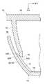
図1には、本発明の車両用ミラー装置が適用された実施の形態に係る車両用ドアミラー装置10の主要部が下方から見た断面図にて示されており、図2には、車両用ドアミラー装置10の主要部が車両後方から見た正面図にて示されている。さらに、図3には、車両用ドアミラー装置10の主要部の一部が車両後方から見た正面図にて示されている。なお、図面では、車両前方を矢印FRで示し、車幅方向一方を矢印WOで示し、上方を矢印UPで示している。 FIG. 1 is a cross-sectional view of a main part of a vehicle
本実施の形態に係る車両用ドアミラー装置10は、車両のドアに設置されており、車両用ドアミラー装置10の内部には、鏡面角度調整装置12が設けられている。 The vehicle
図1〜図3に示す如く、鏡面角度調整装置12は、保持部材を構成する本体部としての略半球形容器状のケース14を備えており、ケース14は、車両用ドアミラー装置10の内部に固定されている。ケース14の車両後側面は、開口されており、ケース14の内周側の車両前側面は、円状の底面16にされている。ケース14の内周側の車両後側面は、環状の配置面18にされており、配置面18は、下記ミラーホルダ36の回動中心Oを中心とした球面状に湾曲されている。 As shown in FIGS. 1 to 3, the mirror surface
ケース14の底面16には、保持部材を構成する固定部としての容器状のケースインナ20が固定されており、ケースインナ20の車両前側面は、開口されている。 A container-like case inner 20 as a fixing portion constituting the holding member is fixed to the
ケース14の底面16には、駆動手段としてのモータ22が一対設けられており、一対のモータ22は、ケースインナ20内に固定されている。モータ22の出力軸は、ケースインナ20外に延出されており、モータ22の出力軸には、ウォーム24が固定されている。 A pair of
ケース14の底面16には、連絡部材としての略円筒状のホイルドライブ26が一対回転自在に支持されている。ホイルドライブ26には、ウォームホイル28が形成されており、ウォームホイル28は、モータ22のウォーム24に噛合(係合)されている。このため、モータ22が駆動されて、ウォーム24が回転されることで、ウォームホイル28が回転されて、ホイルドライブ26が回転される。 A substantially
ホイルドライブ26には、係合部としての噛合爪30が所定数(本実施の形態では4個)一体に形成されており、所定数の噛合爪30は、ホイルドライブ26の周方向に等間隔に配置されている。噛合爪30は、ホイルドライブ26から車両後側へ延出されて、弾性を有しており、噛合爪30の先端(車両後側端)は、ホイルドライブ26の径方向内側に突出されている。 The
ホイルドライブ26内には、駆動部材としての略円軸状のロッドドライブ32が挿入されており、ロッドドライブ32の中心軸周りの回転は、規制されている。一対のロッドドライブ32は、ケース14の配置面18の内周側に配置されており、一方のホイルドライブ26は、配置面18の中心軸の上方又は下方に配置されると共に、他方のホイルドライブ26は、配置面18の中心軸の車幅方向一方又は車幅方向他方に配置されている。 A
ロッドドライブ32の先端部(車両後側端部)以外の部分は、ネジ34にされており、ネジ34には、ホイルドライブ26の噛合爪30先端が噛合(係合)されている。このため、上述の如く、モータ22が駆動されて、ホイルドライブ26(噛合爪30を含む)が回転されることで、噛合爪30先端のネジ34への噛合位置が変位されて、ロッドドライブ32が車両前後方向へ移動される。 A portion other than the tip end portion (vehicle rear side end portion) of the
ケース14の車両後側には、回動部材としてのミラーホルダ36が設けられている。ミラーホルダ36には、略円板状のホルダ部38が形成されており、ミラーホルダ36は、ホルダ部38の中央において、ケースインナ20に回動中心Oを中心として回動可能に保持されている。 A
ロッドドライブ32の先端部(車両後側端部)は、ミラーホルダ36のホルダ部38を回動可能に保持しており、上述の如く、モータ22が駆動されて、ロッドドライブ32が車両前後方向へ移動されることで、ミラーホルダ36が駆動されて回動される。 The front end portion (rear end portion of the vehicle) of the
ホルダ部38の車両前側面には、略半球壁状の回動壁40が一体に形成されており、回動壁40の車両前側面は、開口されている。回動壁40は、ケース14の配置面18の内周側に配置されており、回動壁40の外周面及び内周面は、ミラーホルダ36の回動中心Oを中心とした球面状に湾曲されている。 A rotating
図4に詳細に示す如く、回動壁40の車両前側端全周には、断面矩形状の摺動部42が一体に形成されており、摺動部42は、回動壁40から車両前側かつ径方向外側に突出している。摺動部42の外周面及び内周面は、回動壁40の中心軸を中心とした円周面にされており、摺動部42の車両前側面は、摺動部42の径方向内側へ向かうに従い車両前側へ向かう方向へ傾斜されている。また、摺動部42の外周面と車両前側面との間の角部は、摺動部位42Aにされている。 As shown in detail in FIG. 4, a sliding
図1及び図3に示す如く、摺動部42に対応して、ケース14の配置面18には、断面矩形状の突出部44が所定数(本実施の形態では12個)突出形成されており、所定数の突出部44は、配置面18の中心軸周りの周方向(ミラーホルダ36の回動垂直方向であり、以下「配置面18の横周方向」という)において、等間隔に配置されている。突出部44は、配置面18の回動中心Oを中心としかつ配置面18の中心軸を通過する周方向(ミラーホルダ36の回動方向であり、以下「配置面18の縦周方向」という)に略沿って延在されており(配置面18の横周方向に対し配置面18の縦周方向側に向けられて配置されると共に、配置面18の縦周方向に対し配置面18の横周方向側に向けられて配置されており)、突出部44は、配置面18の縦周方向全体に配置されると共に、配置面18の横周方向側における両縁が互いに平行に配置されている。また、配置面18の突出部44が形成された部分の面積は、配置面18の突出部44が形成されない部分の面積に比し、小さくされている。As shown in FIG. 1 and FIG. 3, corresponding to the sliding
突出部44の突出端面は、接触面44A(摺動部分)にされて、ミラーホルダ36の回動中心Oを中心とした球面状に湾曲されており、突出部44の接触面44Aにおける突出量(肉厚)は、例えば0.2mm以上0.3mm以下にされている。接触面44Aには、ミラーホルダ36の摺動部42の摺動部位42Aが接触(圧接)されており、ミラーホルダ36が回動されることで、摺動部位42Aが接触面44Aを摺動する。また、摺動部位42Aは、曲率(ケース14の配置面18の中心軸が通過する平面における断面の曲率)が接触面44Aに比し大きくされており、摺動部位42Aは、接触面44Aに線接触されている。なお、接触面44Aに接触する摺動部42の摺動部位42Aは、摺動部42の内周面と車両前側面との間の角部や摺動部42の車両前側面の一部又は全体であってもよい。 The projecting end surface of the projecting
回動壁40と配置面18(突出部44を除く)との間には、摺動部位42Aより車両後側(ミラーホルダ36のホルダ部38側)の全体において、隙間46が形成されており、隙間46の径方向寸法は、摺動部42の外周面と配置面18との間を除き、一定にされている。回動壁40と突出部44の接触面44Aとの間には、摺動部位42Aより車両後側の全体において、隙間48が形成されており、隙間48の径方向寸法は、摺動部42の外周面と接触面44Aとの間を除き、一定にされている。また、摺動部位42Aが摺動する接触面44Aの面積は、摺動部位42Aの面積に比し大きくされている。 A
配置面18(突出部44を含む)及び回動壁40(摺動部42を含む)には、潤滑剤(グリス)が塗布されており、潤滑剤によって摺動部位42Aの接触面44Aに対する摺動抵抗が低下されている。 Lubricant (grease) is applied to the placement surface 18 (including the protruding portion 44) and the rotating wall 40 (including the sliding portion 42), and the sliding
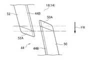
図5に詳細に示す如く、突出部44は、配置面18の縦周方向中央において、車両前側の第1部としての前突出部50と車両後側の第2部としての後突出部52とに分割されている。前突出部50と後突出部52とは、配置面18の横周方向において互いに離間されており、前突出部50と後突出部52との配置面18横周方向における離間距離は、突出部44の配置面18横周方向における離間距離に比し、小さくされている。また、前突出部50の車両後側端部(後突出部52側部分、分割部位)と後突出部52の車両前側端部(前突出部50側部分、分割部位)とは、配置面18の縦周方向において重複配置(オーバーラップ)されている。 As shown in detail in FIG. 5, the projecting
前突出部50の接触面44Aの車両後側縁は、後突出部52側へ向かうに従い車両後側へ向かう方向へ傾斜されており、前突出部50の車両後側端部では、接触面44Aの配置面18横周方向における幅が車両後側へ向かうに従い小さくされている。後突出部52の接触面44Aの車両前側縁は、前突出部50側へ向かうに従い車両前側へ向かう方向へ傾斜されており、後突出部52の車両前側端部では、接触面44Aの配置面18横周方向における幅が車両前側へ向かうに従い小さくされている。さらに、前突出部50の接触面44Aの車両後側縁の車両前側端と後突出部52の接触面44Aの車両前側縁の車両前側端との配置面18の縦周方向における位置は一致されると共に、前突出部50の接触面44Aの車両後側縁の車両後側端と後突出部52の接触面44Aの車両前側縁の車両後側端との配置面18の縦周方向における位置は一致されている。このため、突出部44(前突出部50及び後突出部52の少なくとも一方)の接触面44Aの配置面18横周方向における全体長さ寸法は、配置面18の縦周方向において、突出部44の前突出部50と後突出部52との分割部分を含めて、常に一定にされている。The vehicle rear side edge of the
前突出部50の車両後側端面は、傾斜部としての前傾斜面50Aにされており、前傾斜面50Aは、車両後側へ向かうに従い前突出部50の突出量が小さくなる方向へ傾斜されている(凸状又は凹状に湾曲されてもよい)。後突出部52の車両前側端面は、傾斜部としての後傾斜面52Aにされており、後傾斜面52Aは、車両前側へ向かうに従い後突出部52の突出量が小さくなる方向へ傾斜されている(凸状又は凹状に湾曲されてもよい)。 The vehicle rear side end surface of the front protruding
図1に示す如く、ミラーホルダ36のホルダ部38には、車両後側において、ミラー54が保持されており、ミラー54は、ミラーホルダ36と一体に回動可能にされている。ミラー54の車両後側面は、鏡面54Aにされており、ミラー54によって車両の乗員が車両後側を視認可能にされている。 As shown in FIG. 1, a
次に、本実施の形態の作用を説明する。 Next, the operation of the present embodiment will be described.
以上の構成の車両用ドアミラー装置10では、鏡面角度調整装置12において、モータ22が駆動されて、ウォーム24が回転されることで、ホイルドライブ26(ウォームホイル28及び所定数の噛合爪30を含む)が回転されて、ロッドドライブ32が車両前後方向へ移動される。このため、ロッドドライブ32によってミラーホルダ36及びミラー54が駆動されて、ミラーホルダ36及びミラー54が回動中心Oを中心として上下方向及び車幅方向の少なくとも一方において回動されることで、ミラー54の鏡面54Aの角度が上下方向及び車幅方向の少なくとも一方において調整される。 In the vehicle
ミラーホルダ36が回動される際には、ミラーホルダ36の回動壁40における摺動部42(摺動部位42A)がケース14の配置面18における突出部44(接触面44A)を摺動される。 When the
ここで、突出部44の長手方向が配置面18の横周方向に対し配置面18の縦周方向側に向けられて延在されている。このため、摺動部42が突出部44を摺動されることで、摺動部42と突出部44との間から異物(特に潤滑剤に付着した砂塵等)を突出部44の配置面18横周方向の側方に容易に排出でき、摺動部42と突出部44との間から異物を効果的に排出できる。 Here, the longitudinal direction of the projecting
さらに、突出部44の長手方向が配置面18の縦周方向に対し配置面18の横周方向側に向けられて延在されて、突出部44の配置面18横周方向側の両縁が配置面18の縦周方向に対し配置面18の横周方向側に向けられて延在されている。このため、摺動部42が突出部44の配置面18横周方向側の縁を摺動されることで、摺動部42と突出部44との間から異物を突出部44の配置面18横周方向の側方に一層容易に排出でき、摺動部42と突出部44との間から異物を一層効果的に排出できる。 Furthermore, the longitudinal direction of the projecting
また、突出部44が、配置面18の縦周方向において、前突出部50と後突出部52とに分割されている。このため、摺動部42が突出部44を摺動することで、摺動部42と突出部44との間から異物を前突出部50の車両後側端部外側や後突出部52の車両前側端部外側に排出でき、摺動部42と突出部44との間から異物を一層効果的に排出できる。 Further, the
以上により、摺動部42が突出部44を摺動する際に、摺動部42が突出部44上の異物を搬送することを抑制できると共に、摺動部位42Aと突出部44との間に異物が侵入することを抑制でき、摺動部42が突出部44を円滑に摺動できて、ミラーホルダ36の回動を安定させることができる。 As described above, when the sliding
しかも、配置面18の突出部44が形成されない部分の面積が、配置面18の突出部44が形成された部分の面積に比し、大きくされている。このため、上述の如く突出部44の配置面18横周方向の側方に排出された異物が配置面18の突出部44が形成されない部分に詰まることを抑制でき、当該異物によってミラーホルダ36の回動が阻害されることを抑制できて、ミラーホルダ36の回動を一層安定させることができる。 In addition, the area of the
また、上述の如く、突出部44の長手方向が配置面18の縦周方向に対し配置面18の横周方向側に向けられて延在されている。このため、摺動部42が突出部44を摺動されることで、摺動部42の突出部44に対する摺動位置を配置面18の横周方向へ変動させることができる。これにより、摺動部42の突出部44に対する摺動による摺動部42の磨耗を抑制でき、ミラーホルダ36の耐久性を向上させることができる。 Further, as described above, the longitudinal direction of the projecting
さらに、突出部44の接触面44Aがミラーホルダ36の回動中心Oを中心とした球面状にされている。これにより、摺動部42の突出部44に対する摺動による摺動部42及び突出部44の磨耗を抑制でき、ミラーホルダ36及びケース14の耐久性を向上させることができる。 Further, the
また、前突出部50の車両後側端部と後突出部52の車両前側端部とが配置面18の縦周方向において重複配置されている。このため、摺動部42が前突出部50の車両後側端部と後突出部52の車両前側端部とを同時に摺動でき、ミラーホルダ36の回動を一層安定させることができる。Further, the vehicle rear side end portion of the front projecting
さらに、前突出部50の車両後側端部が接触面44Aの配置面18横周方向における幅を車両後側へ向かうに従い小さくされると共に、後突出部52の車両前側端部が接触面44Aの配置面18横周方向における幅を車両前側へ向かうに従い小さくされることで、突出部44(前突出部50及び後突出部52の少なくとも一方)の接触面44Aの配置面18横周方向における全体長さ寸法が、配置面18の縦周方向において、常に一定にされている。このため、摺動部42が突出部44を摺動する際には、摺動部42が前突出部50の車両後側端部と後突出部52の車両前側端部とを摺動する際でも、摺動部42の突出部44(前突出部50及び後突出部52の少なくとも一方)に対する全体摺動抵抗を常に一定にでき、ミラーホルダ36の回動を一層安定させることができる。Furthermore, the vehicle rear side end of the
また、前突出部50の車両後側端面である前傾斜面50Aが車両後側へ向かうに従い前突出部50の突出量が小さくなる方向へ傾斜されると共に、後突出部52の車両前側端面である後傾斜面52Aが車両前側へ向かうに従い後突出部52の突出量が小さくなる方向へ傾斜されている。このため、摺動部42が前突出部50の車両後側端部と後突出部52の車両前側端部とを摺動する際に、摺動部42が前突出部50の車両後側端面に引掛かることを前傾斜面50Aによって抑制できると共に、摺動部42が後突出部52の車両前側端面に引掛かることを後傾斜面52Aによって抑制でき、ミラーホルダ36の回動を一層安定させることができる。 In addition, the front
さらに、前突出部50の接触面44Aの長手方向寸法が配置面18横周方向の後突出部52側へ向かうに従い大きくされると共に、後突出部52の接触面44Aの長手方向寸法が配置面18横周方向の前突出部50側へ向かうに従い大きくされている。このため、摺動部42が前突出部50の車両後側端部と後突出部52の車両前側端部とを配置面18横周方向の接近した位置において摺動でき、摺動部42を前突出部50の車両後側端部と後突出部52の車両前側端部とによって安定して支持できて、ミラーホルダ36の回動を一層安定させることができる。 Further, the longitudinal dimension of the
なお、本実施の形態では、突出部44(接触面44A)を配置面18の縦周方向に略沿って延在させた。しかしながら、突出部44(接触面44A)を配置面18の縦周方向に沿って延在させてもよい。 In the present embodiment, the protruding portion 44 (
さらに、本実施の形態では、突出部44(接触面44A)の配置面18横周方向側の両縁を配置面18の縦周方向に対し配置面18の横周方向側に向けて延在させた。しかしながら、突出部44(接触面44A)の配置面18横周方向側の少なくとも一方の縁を配置面18の縦周方向に対し配置面18の横周方向側に向けて延在させればよい。 Furthermore, in the present embodiment, both edges of the projecting portion 44 (
また、本実施の形態では、突出部44を配置面18の縦周方向において2個に分割した。しかしながら、突出部44を配置面18の縦周方向において分割しなくてもよく、また、突出部44を配置面18の縦周方向において3個以上に分割してもよい。 Further, in the present embodiment, the protruding
さらに、本実施の形態では、突出部44を断面矩形状にして、摺動部42が摺動する突出部44の接触部を面状の接触面44Aにした。しかしながら、図6に示す如く、例えば、突出部44を断面三角形状にして、摺動部42が摺動する突出部44の接触部を線状の接触線44Bにしてもよい。この場合、前突出部50の接触線44Bが配置面18横周方向の後突出部52側に配置される程好ましく、また、後突出部52の接触線44Bが配置面18横周方向の前突出部50側に配置される程好ましい。これにより、摺動部42が前突出部50の接触線44Bと後突出部52の接触線44Bとを配置面18横周方向の接近した位置において摺動でき、摺動部42を前突出部50と後突出部52とによって安定して支持できる。 Further, in the present embodiment, the projecting
また、本実施の形態では、ミラーホルダ36の回動壁40を略半球壁状にして回動壁40の外周面及び内周面を球面状にした構成とした。しかしながら、回動壁40は摺動部42を設定できる形状であればよく、例えば回動壁40を円筒状等にして回動壁40の外周面及び内周面の少なくとも一方を円周面状にした構成としてもよい。 In the present embodiment, the rotating
さらに、本実施の形態では、ケース14に突出部44を設けると共に、ミラーホルダ36に摺動部42を設けた。しかしながら、ケース14に摺動部42を設けると共に、ミラーホルダ36に突出部44を設けてもよい。 Further, in the present embodiment, the projecting
また、本実施の形態では、本発明を車両用ドアミラー装置10に適用した構成とした。しかしながら、本発明を他の車外や車内のミラー装置に適用した構成としてもよい。 In the present embodiment, the present invention is applied to the vehicle
10 車両用ドアミラー装置(車両用ミラー装置)
14 ケース(保持部材)
20 ケースインナ(保持部材)
36 ミラーホルダ(回動部材)
42 摺動部
44 突出部
50A 前傾斜面(傾斜部)
52A 後傾斜面(傾斜部)
54 ミラー
54A 鏡面10. Vehicle door mirror device (vehicle mirror device)
14 Case (holding member)
20 Case inner (holding member)
36 Mirror holder (rotating member)
42 Sliding
52A Rear inclined surface (inclined part)
54
Claims (5)
Translated fromJapanese前記ミラーが保持される回動部材と、
前記回動部材が回動可能に保持されると共に、配置面が設けられ、前記回動部材が前記配置面に沿って回動されて前記ミラーの鏡面角度が調整される保持部材と、
前記回動部材及び前記保持部材の一方に設けられた摺動部と、
前記回動部材及び前記保持部材の他方に突出して設けられて摺動部分が設けられると共に、前記配置面の中心軸周りの周方向である前記配置面の横周方向に対し前記回動部材の回動中心を中心としかつ前記配置面の中心軸を通過する周方向である前記配置面の縦周方向側に向けられて延在され、かつ、前記配置面の縦周方向において分割されて一方の分割部位と他方の分割部位とが前記配置面の横周方向において離間されると共に前記摺動部分を前記配置面の縦周方向において重複配置され、前記回動部材が回動される際に前記摺動部が前記摺動部分を摺動する突出部と、
を備えた車両用ミラー装置。A mirror provided in the vehicle;
A rotating member for holding the mirror;
Said rotating member is rotatably heldRutotomoni placement surface is provided, and the holding member to which the rotating member is mirror surface angle of the mirror is rotatedalong the placement surface is adjusted,
A sliding portion provided on one of the rotating member and the holding member;
The rotary member and the holding member of the othersliding part provided to projectis provided in Rutotomoni,the rotating member with respect tothe transverse circumferential direction of the arrangement surface is a circumferential direction about the central axis of the placement surfaceAnd extending towardthe longitudinal circumferential side of the placement surface, which is a circumferential direction passing through the central axis of the placement surface , and divided inthe longitudinal circumferential direction of theplacement surface When one divided part and the other divided part are spaced apart inthe lateral circumferential direction of theplacement surface and the sliding portion is placed overlapping inthe longitudinal circumferential direction of theplacement surface, and the turning member is turned A projecting portion on which thesliding portion slides on thesliding portion ;
Mirror device for vehicles provided with.
Priority Applications (3)
| Application Number | Priority Date | Filing Date | Title |
|---|---|---|---|
| JP2012028778AJP6133541B2 (en) | 2012-02-13 | 2012-02-13 | Mirror device for vehicle |
| US13/762,705US9028080B2 (en) | 2012-02-13 | 2013-02-08 | Mirror device for vehicle |
| CN201310051575.1ACN103241181B (en) | 2012-02-13 | 2013-02-08 | Vehicular mirror device |
Applications Claiming Priority (1)
| Application Number | Priority Date | Filing Date | Title |
|---|---|---|---|
| JP2012028778AJP6133541B2 (en) | 2012-02-13 | 2012-02-13 | Mirror device for vehicle |
Publications (2)
| Publication Number | Publication Date |
|---|---|
| JP2013163498A JP2013163498A (en) | 2013-08-22 |
| JP6133541B2true JP6133541B2 (en) | 2017-05-24 |
Family
ID=48921156
Family Applications (1)
| Application Number | Title | Priority Date | Filing Date |
|---|---|---|---|
| JP2012028778AActiveJP6133541B2 (en) | 2012-02-13 | 2012-02-13 | Mirror device for vehicle |
Country Status (3)
| Country | Link |
|---|---|
| US (1) | US9028080B2 (en) |
| JP (1) | JP6133541B2 (en) |
| CN (1) | CN103241181B (en) |
Families Citing this family (13)
| Publication number | Priority date | Publication date | Assignee | Title |
|---|---|---|---|---|
| JP6284415B2 (en)* | 2014-04-15 | 2018-02-28 | サカエ理研工業株式会社 | Mirror surface angle adjustment device |
| KR101575541B1 (en)* | 2014-11-04 | 2015-12-07 | 현대자동차주식회사 | Inside mirror assembly for vehicle |
| JP6385814B2 (en)* | 2014-12-22 | 2018-09-05 | 株式会社東海理化電機製作所 | Visual control device for vehicle |
| JP6463158B2 (en)* | 2015-02-05 | 2019-01-30 | 株式会社東海理化電機製作所 | Vehicle visual recognition device |
| JP2017019462A (en)* | 2015-07-14 | 2017-01-26 | 株式会社東海理化電機製作所 | Visually recognizing device for vehicle |
| JP2017019463A (en)* | 2015-07-14 | 2017-01-26 | 株式会社東海理化電機製作所 | Visually recognizing device for vehicle |
| EP3323678A4 (en)* | 2015-07-14 | 2019-04-10 | Kabushiki Kaisha Tokai Rika Denki Seisakusho | Vehicle visual confirmation device |
| CN107835759A (en)* | 2015-07-14 | 2018-03-23 | 株式会社东海理化电机制作所 | Vehicle visuognosis device |
| JP6649839B2 (en) | 2016-04-15 | 2020-02-19 | 株式会社東海理化電機製作所 | Rotary sliding structure |
| JP7131114B2 (en) | 2018-06-21 | 2022-09-06 | 市光工業株式会社 | Vehicle mirror surface angle adjustment device, vehicle mirror device |
| DE102022109079B3 (en) | 2022-04-13 | 2023-08-24 | Motherson Innovations Company Limited | ACTUATOR, REAR VIEW DEVICE AND VEHICLE |
| DE102022109087B3 (en) | 2022-04-13 | 2023-09-07 | Motherson Innovations Company Limited | ACTUATOR, REAR VIEW DEVICE AND VEHICLE |
| GB2635821A (en)* | 2023-09-19 | 2025-05-28 | Motherson Innovations Co Ltd | Actuator, rear view device, and vehicle |
Family Cites Families (13)
| Publication number | Priority date | Publication date | Assignee | Title |
|---|---|---|---|---|
| JPH0450042A (en)* | 1990-06-19 | 1992-02-19 | Ichikoh Ind Ltd | Electric remote control mirror |
| JPH08132964A (en)* | 1994-11-10 | 1996-05-28 | Ichikoh Ind Ltd | Vehicle outside mirror device |
| US6168279B1 (en)* | 1998-03-25 | 2001-01-02 | Donnelly Corporation | Pivot support for adjustable rearview mirror |
| DE19902756A1 (en)* | 1999-01-25 | 2000-07-27 | Buhler Motor Gmbh | Adjustable external rear view mirror for motor vehicles has first and second part moving over facing surfaces, which enclose space for impurities |
| ES2190868B1 (en)* | 2001-03-30 | 2005-02-01 | Fico Mirrors, S.A. | MANUAL REGULATION MECHANISM FOR EXTERIOR REAR VIEW MACHINES OF MOTOR VEHICLES. |
| DE10163318C1 (en)* | 2001-12-21 | 2003-08-28 | Mekra Lang Gmbh & Co Kg | Articulated device in particular for adjusting rear view mirrors for motor vehicles |
| DE602004020151D1 (en) | 2003-07-10 | 2009-05-07 | Ichikoh Industries Ltd | Device for tilt adjustment of an exterior mirror |
| JP4493380B2 (en)* | 2004-03-30 | 2010-06-30 | サカエ理研工業株式会社 | Electric mirror device |
| JP4705039B2 (en)* | 2004-10-08 | 2011-06-22 | 株式会社村上開明堂 | Mirror surface angle adjustment device |
| EP1798105A1 (en) | 2004-10-08 | 2007-06-20 | Murakami Corporation | Mirror angle adjusting device |
| US7637683B2 (en)* | 2006-04-09 | 2009-12-29 | Lang Mekra North America, Llc | Sliding structure |
| KR200421538Y1 (en)* | 2006-05-02 | 2006-07-12 | 주식회사 액트로닉스 | Assembly Structure of Automotive Side Mirrors |
| JP5775263B2 (en)* | 2010-02-08 | 2015-09-09 | 株式会社東海理化電機製作所 | Mirror device for vehicle |
- 2012
- 2012-02-13JPJP2012028778Apatent/JP6133541B2/enactiveActive
- 2013
- 2013-02-08USUS13/762,705patent/US9028080B2/enactiveActive
- 2013-02-08CNCN201310051575.1Apatent/CN103241181B/enactiveActive
Also Published As
| Publication number | Publication date |
|---|---|
| CN103241181B (en) | 2015-08-05 |
| CN103241181A (en) | 2013-08-14 |
| US20130208373A1 (en) | 2013-08-15 |
| US9028080B2 (en) | 2015-05-12 |
| JP2013163498A (en) | 2013-08-22 |
Similar Documents
| Publication | Publication Date | Title |
|---|---|---|
| JP6133541B2 (en) | Mirror device for vehicle | |
| CN103052819B (en) | Sealing device for a rolling bearing | |
| CN103542004A (en) | Hub bearing assembly with a sealing device | |
| US8915548B2 (en) | Fitting for a vehicle seat | |
| US7962998B2 (en) | Roller support assemblies | |
| JP5775263B2 (en) | Mirror device for vehicle | |
| US9139041B2 (en) | Arrangement of a wheel hub connected to a constant velocity joint provided with a flexible seal device | |
| US8344583B2 (en) | Slip ring cover for automotive alternator | |
| US7267485B2 (en) | Annular disk for a sliding bearing | |
| CN103237681A (en) | Fitting for vehicle seat and method for producing same | |
| CN105291907A (en) | Angular adjustment device for a vehicle seat | |
| CN105299059A (en) | Vehicle hub bearing unit provided with a protective ring | |
| CN103443506B (en) | Unload band instrument | |
| JP2020133706A (en) | Hub unit bearing | |
| WO2021059626A1 (en) | Sealing device | |
| CN104870843A (en) | Bearing assembly | |
| JP6129488B2 (en) | Mirror device for vehicle | |
| US10955006B2 (en) | Radial shaft seal with dynamic exclusion of contamination | |
| CN102548691B (en) | Internal milling cutter | |
| JP2014156879A (en) | Supporting structure of floating bearing | |
| US10974545B2 (en) | Wheel bearing arrangement for a motor vehicle | |
| EP2551542B1 (en) | Wheel-hub bearing/constant-velocity joint unit provided with a protective screen | |
| JP6200252B2 (en) | Sealing device | |
| JP6313162B2 (en) | Vehicle side mirror | |
| CN106286732A (en) | tension roller device |
Legal Events
| Date | Code | Title | Description |
|---|---|---|---|
| A621 | Written request for application examination | Free format text:JAPANESE INTERMEDIATE CODE: A621 Effective date:20140919 | |
| A871 | Explanation of circumstances concerning accelerated examination | Free format text:JAPANESE INTERMEDIATE CODE: A871 Effective date:20140919 | |
| A975 | Report on accelerated examination | Free format text:JAPANESE INTERMEDIATE CODE: A971005 Effective date:20141007 | |
| A131 | Notification of reasons for refusal | Free format text:JAPANESE INTERMEDIATE CODE: A131 Effective date:20141111 | |
| A521 | Request for written amendment filed | Free format text:JAPANESE INTERMEDIATE CODE: A523 Effective date:20141218 | |
| A131 | Notification of reasons for refusal | Free format text:JAPANESE INTERMEDIATE CODE: A131 Effective date:20150324 | |
| A521 | Request for written amendment filed | Free format text:JAPANESE INTERMEDIATE CODE: A523 Effective date:20150519 | |
| A131 | Notification of reasons for refusal | Free format text:JAPANESE INTERMEDIATE CODE: A131 Effective date:20150721 | |
| A521 | Request for written amendment filed | Free format text:JAPANESE INTERMEDIATE CODE: A523 Effective date:20150831 | |
| A02 | Decision of refusal | Free format text:JAPANESE INTERMEDIATE CODE: A02 Effective date:20151104 | |
| A521 | Request for written amendment filed | Free format text:JAPANESE INTERMEDIATE CODE: A523 Effective date:20160127 | |
| A911 | Transfer to examiner for re-examination before appeal (zenchi) | Free format text:JAPANESE INTERMEDIATE CODE: A911 Effective date:20160204 | |
| A912 | Re-examination (zenchi) completed and case transferred to appeal board | Free format text:JAPANESE INTERMEDIATE CODE: A912 Effective date:20160408 | |
| A521 | Request for written amendment filed | Free format text:JAPANESE INTERMEDIATE CODE: A523 Effective date:20161226 | |
| A61 | First payment of annual fees (during grant procedure) | Free format text:JAPANESE INTERMEDIATE CODE: A61 Effective date:20170420 | |
| R150 | Certificate of patent or registration of utility model | Ref document number:6133541 Country of ref document:JP Free format text:JAPANESE INTERMEDIATE CODE: R150 |