JP6131650B2 - Electronic device with power generation function - Google Patents
Electronic device with power generation functionDownload PDFInfo
- Publication number
- JP6131650B2 JP6131650B2JP2013054560AJP2013054560AJP6131650B2JP 6131650 B2JP6131650 B2JP 6131650B2JP 2013054560 AJP2013054560 AJP 2013054560AJP 2013054560 AJP2013054560 AJP 2013054560AJP 6131650 B2JP6131650 B2JP 6131650B2
- Authority
- JP
- Japan
- Prior art keywords
- electronic device
- temperature
- power generation
- heat
- thermoelectric conversion
- Prior art date
- Legal status (The legal status is an assumption and is not a legal conclusion. Google has not performed a legal analysis and makes no representation as to the accuracy of the status listed.)
- Expired - Fee Related
Links
Images


Landscapes
- Measuring And Recording Apparatus For Diagnosis (AREA)
- Measuring Pulse, Heart Rate, Blood Pressure Or Blood Flow (AREA)
Description
Translated fromJapanese本発明は、発電機能を備えた電子装置に関する。 The present invention relates to an electronic device having a power generation function.
近年、食品の安全性を確保するという観点から、牛や豚等の家畜のトレーサビリティーが要求されている。このため、例えば家畜の耳に数字や文字又はバーコード等の個体識別記号を付した個体識別用タグを取り付けるなどの対策が採られている。 In recent years, traceability of livestock such as cattle and pigs has been demanded from the viewpoint of ensuring food safety. For this reason, for example, measures are taken such as attaching individual identification tags with individual identification symbols such as numbers, letters or bar codes to the ears of livestock.
また、個体識別用タグに温度センサを取り付けて、家畜の健康管理に使用することが提案されている。この種の個体識別用タグは、温度センサで検出した温度のデータを無線により端末装置に送信するための電子回路と、電子回路を駆動するための電池とを備えている。 In addition, it has been proposed to attach a temperature sensor to the individual identification tag and use it for health management of livestock. This type of individual identification tag includes an electronic circuit for wirelessly transmitting temperature data detected by a temperature sensor to a terminal device, and a battery for driving the electronic circuit.
一方、動物の体内に埋め込んで個体識別に使用するマイクロチップが実用化されている。この種のマイクロチップは、ガラス管内にアンテナコイルと近距離無線通信機能を備えたICチップとを封入した構造を有する。ICチップには個体識別記号(電子データ)が書き込まれているだけでなく、温度センサが設けられている。 On the other hand, a microchip that is embedded in an animal body and used for individual identification has been put into practical use. This type of microchip has a structure in which an antenna coil and an IC chip having a short-range wireless communication function are enclosed in a glass tube. The IC chip is provided not only with an individual identification symbol (electronic data) but also with a temperature sensor.
専用の読み取り装置をマイクロチップに近付けると、読み取り装置から送信される電磁波によりICチップに駆動用電力が供給される。そして、ICチップから読み取り装置に、個体識別記号と温度センサにより検出した温度の情報とが送信される。 When a dedicated reading device is brought close to the microchip, driving power is supplied to the IC chip by electromagnetic waves transmitted from the reading device. Then, the individual identification symbol and the temperature information detected by the temperature sensor are transmitted from the IC chip to the reading device.
長期間にわたる生体の状態観測に使用できる発電機能を備えた電子装置を提供することを目的とする。 An object of the present invention is to provide an electronic device having a power generation function that can be used for observing the state of a living body over a long period of time.
開示の技術の一観点によれば、生体の耳に取り付ける耳標部と、前記生体の耳穴に挿入される挿入部と、前記挿入部に設けられて前記生体の体温により温められる熱吸収部と、前記挿入部と前記耳標部とを接続する伝熱部材と、前記耳標部に設けられて一方の面に前記伝熱部材を介して前記熱吸収部の熱が伝達され、他方の面に空気の熱が伝達されて、前記一方の面と前記他方の面の温度差により電気を発生する熱電変換素子と、前記耳標部に設けられて前記熱電変換素子で発生する電気により駆動する電子回路部とを有する発電機能を備えた電子装置が提供される。According to one aspect of the disclosed technology, anear tag part to be attached to an ear of a living body, an insertion part to be inserted intoan ear hole of the living body, a heat absorption part provided in the insertion part and warmed by the body temperature of the living body,the a heat transfer member which connects the insertion portion and with said ear tags section, the ear tag part heatof the heat absorbing partthrough the heat transfer member on one surfaceprovided is transmitted, the other surface The heat of the air is transmitted to the thermoelectric conversion element that generates electricity due to the temperature difference between the one surface and the other surface, and is driven by the electricitythat is provided in the ear tag portion and is generated by the thermoelectric conversion element. An electronic device having a power generation function having an electronic circuit unit is provided.
上記一観点に係る発電機能を備えた電子装置によれば、生体の体温を利用して発電するので、長期間にわたる生体の状態観測に使用できる。 According to the electronic device having the power generation function according to the above aspect, power generation is performed using the body temperature of the living body, and therefore, it can be used for observation of the state of the living body over a long period of time.
以下、実施形態について説明する前に、実施形態の理解を容易にするための予備的事項について説明する。 Hereinafter, before describing the embodiment, a preliminary matter for facilitating understanding of the embodiment will be described.
前述した温度センサを備えた個体識別用タグでは、内蔵電池の管理や交換等の作業が煩雑である。電源として太陽電池を使用することも考えられるが、太陽電池は天候等により発電量が安定せず、夜間や雨の日に使用できなくなってしまう。このため、温度センサを備えた個体識別用タグの電源として太陽電池を使用した場合は、長期間継続して体温を観測することが困難になる。 In the individual identification tag provided with the temperature sensor described above, operations such as management and replacement of the built-in battery are complicated. Although it is conceivable to use a solar cell as a power source, the solar cell cannot be used at night or on rainy days because its power generation amount is not stable due to the weather or the like. For this reason, when a solar cell is used as a power source for an individual identification tag provided with a temperature sensor, it becomes difficult to observe body temperature continuously for a long period of time.
一方、アンテナコイルとICチップとをガラス管内に封入したマイクロチップでは、読み取り装置から電磁波を介して電力が供給されるので、電池の管理や交換等の作業は必要ない。しかし、電磁波の到達距離が極めて短いため、読み取り装置をマイクロチップに数cmまで近付けないと使用できない。そのため、家畜の体温を常時観測することは困難である。 On the other hand, in a microchip in which an antenna coil and an IC chip are enclosed in a glass tube, power is supplied from a reading device via electromagnetic waves, so that work such as battery management and replacement is not necessary. However, since the reach of electromagnetic waves is extremely short, the reader cannot be used unless it is close to a microchip up to several centimeters. Therefore, it is difficult to always observe the body temperature of livestock.
以下の実施形態では、長期間にわたる生体の状態観測に使用できる発電機能を備えた電子装置について説明する。 In the following embodiments, an electronic device having a power generation function that can be used for observing the state of a living body over a long period of time will be described.
(第1の実施形態)
図1は第1の実施形態に係る発電機能を備えた電子装置を示す模式平面図、図2は図1のI−I線による断面図である。本実施形態は、牛や豚等の家畜の耳に装着する耳標に適用した例について説明している。(First embodiment)
FIG. 1 is a schematic plan view showing an electronic apparatus having a power generation function according to the first embodiment, and FIG. 2 is a cross-sectional view taken along the line II of FIG. This embodiment demonstrates the example applied to the ear tag with which the domestic animals, such as a cow and a pig, are mounted | worn.
本実施形態に係る発電機能を備えた電子装置10は、家畜の耳に取り付ける耳標部11と、耳穴(以下、「外耳道」という)に挿入する耳挿入部12と、耳挿入部12と耳標部11との間を連絡する伝熱部13とを有する。耳挿入部12には、温度センサ26が設けられている。なお、外耳道は、生体の開口部の一例である。 An
耳標部11は樹脂により形成された薄く柔軟性を有するシート状の部材であり、家畜の耳に取り付けるための穴11aが設けられている。この耳標部11の一方の面には個体識別記号(図1の例では14桁の数字)が印刷されており、他方の面側には放熱シート22が配置されている。 The
放熱シート22は、熱伝導性が良好な金属、セラミック又はグラファイト等の材料により形成されている。放熱シート22は、家畜を傷つけないように、柔軟性がある材料又は構造であることが好ましい。放熱シート22は金属箔のように表面が平坦なものでもよいが、放熱効果を上げるためにフィンや突起を設けて表面積を大きくしてもよい。 The
また、耳標部11には、熱電変換素子23と、二次電池24と、電子回路部25とが設けられている。 The
熱電変換素子23はゼーベック効果を利用して熱エネルギーを電気エネルギーに変換する素子であり、BiTe系材料を用いた一般的なπ型熱電変換素子を使用することができる。熱電変換素子23のサイズは、例えば縦が数mm、横が数mm、厚さが1mm以下である。 The
二次電池24は耳標部11に内蔵できる程度の薄さと十分な蓄電容量とを備えていればよく、例えば薄膜リチウム二次電池を使用することができる。二次電池24は、蓄電素子の一例である。 The
電子回路部25は、図3のブロック図に示すように、充電回路部25aと、記憶部25bと、通信部25cと、制御部25dとを有する。この電子回路部25の主要部は、微小なサイズの半導体チップ(ICチップ)に集積化されている。 As shown in the block diagram of FIG. 3, the
充電回路部25aは、熱電変換素子23で発生した電力を所定の電圧に昇圧する昇圧回路と、二次電池24の充放電を制御する充放電制御回路とを有する。記憶部25bには個体識別記号(電子データ)が記憶されている。通信部25cは、ZigBee(ジグビー)又はBluetooth(ブルートゥース)等の近距離無線通信により外部装置15との間で通信を行う。 The
制御部25dは、適宜、記憶部25bから個体識別記号を読み出す。また、制御部25dは、適宜、温度センサ26の出力を信号処理する。そして、制御部25dは、適宜通信部25cを制御して、個体識別記号や温度センサ26による温度検出結果のデータを外部装置15に送信する。 The
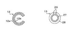
耳挿入部12は、図1の模式平面図及び図4(a)の断面図に示すように、断面が“C”状に形成されたほぼ円筒状の部材であり、前述したように温度センサ26を備え、家畜の外耳道に挿入される。 As shown in the schematic plan view of FIG. 1 and the cross-sectional view of FIG. 4A, the
本実施形態で用いる耳挿入部12は、アルミニウム等の熱伝導性が良好な材料によりC−リング状に形成された吸熱部12aと、吸熱部12aの内側に配置された形状記憶合金よりなる形状記憶部12bとの2層構造を有する。 The
吸熱部12aは、外耳道の壁面(皮膚)から熱を吸収するためのものである。また、形状記憶部12bは、外耳道に挿入された耳挿入部12を所定の形状にして吸熱部12aの外周面を外耳道の壁面に密着させるためのものである。形状記憶合金よりなる形状記憶部12bに替えて、C−リング状のばねを使用してもよい。また、吸熱部12aが適度のばね性を有する場合は、形状記憶部12bがなくてもよい。 The
温度センサ26は、耳挿入部12を外耳道に挿入したときに、外耳道の壁面に接触する。温度センサ26として、熱電対又は半導体温度センサ等を使用することができる。 The
伝熱部13は、耳挿入部12で吸収した熱を耳標部11の熱電変換素子23に伝達する部材であり、図1の模式平面図及び図4(b)の断面図に示すように、ヒートパイプ27と、ヒートパイプ27を被覆する断熱性被膜28とを備える。また、伝熱部13には、温度センサ26と電子回路部25との間を電気的に接続する配線29が設けられている。この配線29も、断熱性被膜28に被覆されている。 The
なお、本実施形態で使用しているヒートパイプ27は、内部に封入された作動液の気相と液相との変化を利用して、高温側(耳挿入部12側)から低温側(耳標部11側)に熱を輸送する。ヒートパイプ27に替えて、熱伝導性が良好な材料により形成された棒状又はワイヤ状の部材を使用してもよい。 Note that the
図2に示すように、ヒートパイプ27の耳標部11側の端部は、伝熱板21を介して熱電変換素子23と熱的に接続されている。また、ヒートパイプ27の他方の端部は、耳挿入部12の吸熱部12aと熱的に接続されている。 As shown in FIG. 2, the end of the
ヒートパイプ27により耳挿入部12から輸送されてきた熱は、伝熱板21を介して熱電変換素子23に伝達される。熱電変換素子23は、一方の面に接触する伝熱板21の温度と、他方の面に接触する放熱シート22の温度との差により電気を発生する。 The heat transported from the
一般的に、牛や豚等の家畜の体温は37℃〜39℃程度であり、放熱シート22の温度は外気温となるので、外気温が25℃とすると熱電変換素子23には常時10℃以上の温度差が与えられる。 Generally, the body temperature of livestock such as cattle and pigs is about 37 ° C. to 39 ° C., and the temperature of the
熱電変換素子23で発生した電気は二次電池24に蓄積され、二次電池24に蓄積された電気により電子回路部25が動作して、温度センサ26で検出した温度や個体識別記号のデータが外部装置15に無線で送信される。 Electricity generated by the
このように、本実施形態に係る電子装置10の熱電変換素子23は、生体の体温と外気温との差を利用して発電するので、天候や時間に関係なく常に電気を発生する。そして、本実施形態では、熱電変換素子23で発生した電気を二次電池24に蓄積していくので、個体識別記号や温度センサ26による温度測定結果を外部装置15に送信する際に、電子回路部25は比較的大きな電力を使用することができる。 Thus, since the
これにより、電子装置10と外部装置15との間の距離がある程度離れていても、電子装置10と外部装置15との間で通信を行うことができる。また、本実施形態では、熱電変換素子23により半永久的に電気が供給されるので、生体の状態(この例では体温)を長期間にわたって観測することができる。更に、本実施形態に係る電子装置10は、電池の管理や交換等の作業が基本的に必要ないので、取り扱いが容易である。 Thereby, even if the distance between the
以下、本実施形態に係る電子装置10を実際に作製し、畜牛に取り付けて体温測定(状態観測)を行った実験結果について説明する。 Hereinafter, an experimental result of actually producing the
作製した電子装置10の耳標部11は、縦及び横の長さがいずれも8cm程度である。この耳標部11には、図1のように放熱シート22、熱電変換素子23、二次電池24及び電子回路25が設けられている。 The
耳挿入部12は、アルミニウム製の吸熱部12aと、その内側に配置された形状記憶部12bとの2層構造を有する。形状記憶部12bには変態点が20℃〜30℃程度の形状記憶合金を使用しており、温度が形状記憶合金の変態点以上のときの耳挿入部12の直径は約10mmである。 The
伝熱部13は、直径が2.5mm、長さが15cmのヒートパイプ27と、ヒートパイプ27の外周を被覆する発泡樹脂よりなる断熱被膜28と、温度センサ26と電子回路部25との間を電気的に接続する配線29とを有する。 The
作製した電子装置10の耳標部11を牛の耳たぶに取り付け、耳挿入部12を牛の外耳道に挿入した。耳挿入部12を挿入する際には約10℃の温度下で耳挿入部12の径を縮小した。また、牛の外耳道に傷を付けることを防止するために、耳挿入部12の外周面に乳剤を塗布した。 The
耳挿入部12を牛の外耳道に挿入すると、数分後に牛の体温により形状記憶部12bが温められて耳挿入部12の径が広がり、耳挿入部12の外周面と牛の外耳道とが密着した。この間、牛の行動に異常は見られなかった。 When the
実験に使用した電子装置10は、10分毎に個体識別記号のデータと体温(外耳道の温度)のデータとを、2.4GHzの周波数帯を使用したZigBeeにより送信する。電子装置10を牛の耳たぶに取り付けてから1カ月の間、無線送信が途切れることは一度もなかった。 The
実験に使用した電子装置10では、熱電変換素子23として、BiTe系材料を用いたπ型熱電変換素子を使用している。この熱電変換素子23の発電能力は気温により変化するが、気温が35℃のときには約13μW、気温が30℃のときには約50μW、気温が25℃のときには約113μW、気温が20℃のときには約200μW、気温が15℃のときには約312μW、気温が10℃のときには約450μWの発電量となる。 In the
一方、10分毎に1回の割合で個体識別記号と体温の測定結果のデータとを送信した場合の平均消費電力は約10μWであった。従って、気温が35℃を超えなければ、熱電変換素子23で発生する電力で無線送信の出力を十分に賄えることが確認できた。 On the other hand, the average power consumption when the individual identification symbol and the data of the measurement result of the body temperature were transmitted at a rate of once every 10 minutes was about 10 μW. Therefore, it was confirmed that if the temperature does not exceed 35 ° C., the power generated by the
なお、実験に使用した電子装置10では、二次電池24として容量が100μWhの薄膜リチウム二次電池を使用している。この場合、二次電池24に約10時間分の電力を蓄積できるため、気温が一時的に35℃以上となっても、通信が途切れることはない。 In the
図5は、横軸に時刻をとり、縦軸に温度をとって、電子装置10により牛の外耳道の温度を測定した結果を示す図である。図5には、直腸の温度を測定した結果と、耳標に取り付けた温度センサにより耳たぶの温度を測定した結果と、気温の変化を測定した結果とを併せて示している。通常、牛の体温測定は、直腸の温度を測定することにより行われている。 FIG. 5 is a diagram showing the result of measuring the temperature of the ear canal of the cow by the
図5から、外耳道の温度測定結果は直腸の温度測定結果よりも0.8℃程度低くなるが、直腸の温度測定結果と同様に気温の変化には影響されないことがわかる。また、直腸の温度測定では排便時に大きな温度変化が観測されるが、外耳道の温度測定ではそのような影響はなく、常に正確な体温計測ができることがわかる。 FIG. 5 shows that the temperature measurement result of the ear canal is lower by about 0.8 ° C. than the temperature measurement result of the rectum, but is not affected by the change in the temperature as in the case of the temperature measurement of the rectum. In addition, a large temperature change is observed during defecation in the rectal temperature measurement, but in the ear canal temperature measurement, there is no such influence, and it can be seen that accurate body temperature measurement can always be performed.
更に、図5から、耳標に温度センサを取り付けて耳たぶの温度測定した場合は、気温に応じて測定結果が大きく変化してしまうため、牛の体温を正確に測定できないことがわかる。 Furthermore, FIG. 5 shows that when the temperature sensor is attached to the ear tag and the temperature of the earlobe is measured, the measurement result greatly changes according to the air temperature, so that the body temperature of the cow cannot be measured accurately.
以上の実験結果から、開示の技術の有用性が確認された。なお、本実施形態では温度センサ26を用いて生体の温度を測定する場合について説明したが、脈波を検出するセンサや、血中酸素濃度を測定するセンサ等を用いて、脈波や血中酸素濃度等を測定するようにしてもよい。 From the above experimental results, the usefulness of the disclosed technology was confirmed. In the present embodiment, the case where the temperature of the living body is measured using the
また、上記の例では一定の時間(10分毎)に電子装置10と外部装置15との間で通信を行うものとしているが、電子装置10内に受信器を設け、外部装置15からの信号をトリガーとして通信を行うようにしてもよい。更に、外部装置15から電子装置10の電子回路部25に、個体識別記号やその他の情報を随時書き込めるようにしてもよい。 In the above example, communication is performed between the
(第2の実施形態)
図6は第2の実施形態に係る発電機能を備えた電子装置を示す断面図、図7は同じくその電子装置の概観を示す斜視図である。また、図8は、同じくその電子装置の一部を拡大して示す模式断面図である。(Second Embodiment)
FIG. 6 is a cross-sectional view showing an electronic device having a power generation function according to the second embodiment, and FIG. 7 is a perspective view showing an overview of the electronic device. FIG. 8 is a schematic cross-sectional view showing an enlarged part of the electronic device.
本実施形態は、家畜や人の鼻の穴(以下、「鼻孔」という)に挿入して健康状態の管理に使用する電子装置に適用した例について説明する。鼻孔は、生体の開口部の一例である。 In the present embodiment, an example will be described in which the present invention is applied to an electronic device that is inserted into livestock or a human nostril (hereinafter referred to as “nasal passage”) and used for health management. A nostril is an example of an opening of a living body.
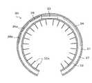
本実施形態に係る発電機能を備えた電子装置30は、図6,図7に示すように、断面が“C”字状に形成されたほぼ円筒状の部材であり、外周面を形成する吸熱部31と、内周面を形成する放熱部32とを有する。 As shown in FIGS. 6 and 7, the
放熱部32の周面には、図7に示すように、放熱部32の中心軸方向に沿って、“C”字状に形成された複数の形状記憶合金からなる形状記憶リング38が配置されている。これらの形状記憶リング38は、鼻孔に挿入された電子装置30を所定の形状にして吸熱部32を鼻孔の壁面に密着させるためのものである。 As shown in FIG. 7, a
形状記憶合金からなる形状記憶リング38に替えて、“C”字状のばねを使用してもよい。また、吸熱部31又は放熱部32が適度のばね性を有する場合は、形状記憶リング38がなくてもよい。 Instead of the
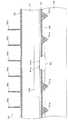
吸熱部31と放熱部32との間には、図6に示すように、熱電変換素子33、二次電池34、電子回路部35及びセンサ素子36a,36bが配置され、且つ断熱材37が充填されている。断熱材37は薄くても良好な断熱性を有することが好ましく、例えばポリオレフィン系の発泡樹脂を使用することができる。 As shown in FIG. 6, the
吸熱部31は、例えば銅箔又はアルミニウム箔等の金属箔やグラファイトシートなどのように、柔軟性があり、熱伝導率が高い材料により形成されている。この吸熱部31は、鼻孔の壁面(皮膚)に接触して体温を吸収する。 The
鼻孔の壁面には毛が生えており、起伏もあるため、吸熱部31と鼻孔の壁面との間には熱抵抗となる隙間が発生しやすい。そこで、本実施形態では、図8に示すように、吸熱部31の外周面(鼻孔の壁面側の面)に高さが1mm程度の多数の微細な突起31aを設けて、吸熱部31と鼻孔の壁面との接触面積を大きくしている。なお、図8中の符号40は鼻孔の壁面(皮膚)を示している。 Since the hair on the nostril wall is raised and undulated, there is a tendency for a gap between the
また、本実施形態では、熱抵抗をより一層小さくするために、吸熱部31の外周面に、熱伝導率が高く、生体親和性に優れる被膜39を付着させている。この被膜39は、例えば親水性シリコーン樹脂からなるハイドロゲルに、熱伝導率が高いアルミナや金の粒子又はカーボンナノチューブなどを分散させたものである。 In the present embodiment, in order to further reduce the thermal resistance, a
一方、放熱部32も、吸熱部31と同様に、例えば銅箔又はアルミニウム箔等の金属箔やグラファイトシートなどのように、柔軟性があり、熱伝導率が高い材料により形成されている。この放熱部32は、呼吸のたびに鼻孔内を流れる空気により冷却される。 On the other hand, the
放熱部32は鼻孔内を流れる空気との間で効率よく熱交換できることが重要である。本実施形態では、放熱部32の放熱面積を増やすために、放熱部32の周面に微細なフィン32aを設けている。フィン32aに替えて、棒状の突起等を設けてもよい。また、鼻孔内の分泌物やごみの付着を抑制するために、放熱部32の表面は撥水性となっていることが好ましい。 It is important that the
熱電変換素子33の一方の面は吸熱部31に接触し、他方の面は放熱部32に接触している。そして、熱電変換素子33は、一方の面側の温度と他方の面側の温度との差に応じた電力を発生する。熱電変換素子33として、第1の実施形態と同様に、BiTe系材料を用いたπ型の一般的な熱電変換素子を使用することができる。吸熱部31と放熱部32との間に複数の熱電変換素子33を配置してもよい。 One surface of the
二次電池34は、吸熱部31と放熱部32との間に内蔵できる程度の薄さと十分な蓄電容量とを備えていればよい。本実施形態においても第1の実施形態と同様に、二次電池34として、薄膜リチウム二次電池を使用するものとする。 The
センサ素子36aには、生体の温度を検出する温度センサが設けられている。また、センサ素子36bは、赤外線を使用して心拍、血中酸素濃度及び血糖値等を測定するものであり、図8に示すように、発光部41aと、受光部41bと、透明部材42とを有する。透明部材42は、吸熱部31に開口された窓に挿入されて配置される。 The
このセンサ素子36bは、発光部41aから赤外線を出射する。発光部41aから出射された赤外線は、透明部材42を透過して鼻孔の壁面に到達し、鼻孔の壁面やその近傍の血管中を流れる血液等により反射される。そして、鼻孔の壁面やその近傍の血管中を流れる血液等により反射された光は、透明部材42を透過して受光部41bに到達する。受光部41bは、鼻孔の壁面及びその近傍で反射された光のうち特定の波長の光を受光し、その強度に応じた信号を出力する。 The
電子回路部35は、図9のブロック図に示すように、充電回路部35aと、記憶部35bと、通信部35cと、制御部35dとを有する。この電子回路部35の主要部は、微小なサイズの半導体チップ(ICチップ)に集積化されている。 As shown in the block diagram of FIG. 9, the
充電回路部35aは、熱電変換素子33で発生した電力を所定の電圧に昇圧する昇圧回路と、二次電池34の充放電を制御する充放電制御回路とを有する。 The charging
記憶部35bには個体識別記号(電子データ)が記憶されている。通信部35cは、ZigBee(ジグビー)又はBluetooth(ブルートゥース)等の近距離無線通信により外部装置15との間で通信を行う。 An individual identification symbol (electronic data) is stored in the
制御部35dは、適宜、記憶部35bから個体識別記号を読み出す。また、制御部35dは、センサ素子36a,36bから出力される信号を信号処理するとともに、充電回路部35aを介して熱電変換素子33の出力電圧を検出する。 The
そして、制御部35dは、適宜通信部35cを制御して、個体識別記号、熱電変換素子33の出力電圧、及びセンサ部36a,36bの出力信号のデータを、外部装置15に送信する。 Then, the
外部装置15では、電子装置30から送られてくるデータに基づいて、呼吸数、体温、心拍数、血中酸素濃度及び血糖値等を検出する。 The
呼吸数は、熱電変換素子33の出力電圧から検出する。すなわち、空気を吸うときと吐くときとで鼻孔内を流れる気流の温度が変化するので、熱電変換素子33の出力電圧は呼吸にともなって変化する。このため、熱電変換素子33の出力電圧の変化から、呼吸数を検出することができる。 The respiratory rate is detected from the output voltage of the
また、外部装置15は、センサ素子36aの出力から体温を検出する。更に、外部装置15は、赤外線を出射及び受光するセンサ素子36bの出力から、心拍数、血中酸素濃度及び血糖値等を検出する。 The
赤外線を用いて心拍、血中酸素濃度及び血糖値等を検出する方法として、指先や耳たぶ等の体表面に赤外線を照射し、反射光又は透過光を検出する方法が知られている。しかし、鼻孔壁面では血管が皮膚表面に極めて近い部分にあるので、鼻孔の壁面に赤外線を照射する方法は、指先や耳たぶ等に赤外線を照射する方法に比べて高感度であり、測定に必要な電力が少なくてすむ。 As a method for detecting heartbeat, blood oxygen concentration, blood glucose level, and the like using infrared rays, a method is known in which reflected light or transmitted light is detected by irradiating a body surface such as a fingertip or an earlobe with infrared rays. However, because the blood vessels are very close to the skin surface on the wall of the nostril, the method of irradiating infrared rays to the wall of the nostril is more sensitive than the method of irradiating infrared rays to the fingertips, ear lobes, etc. Less power is required.
上述したように、本実施形態に係る電子装置30の熱電変換素子33は、生体の体温と鼻孔内を流れる空気の温度との差を利用して発電するので、天候や時間に関係なく常に電気を発生する。そして、本実施形態では、熱電変換素子33で発生した電気を二次電池34に蓄積していくので、個体識別記号やセンサ部36a,36bから出力される信号を外部装置15に送信する際に、電子回路部35は比較的大きな電力を使用することができる。 As described above, the
これにより、電子装置30と外部装置15との間の距離がある程度離れていても、電子装置30と外部装置15との間で通信を行うことができる。また、本実施形態では、熱電変換素子33により半永久的に電気が供給されるので、生体の状態を長期間にわたって観測することができる。更に、本実施形態に係る電子装置30は、電池の管理や交換等の作業が基本的に必要ないので、取り扱いが容易である。 Thereby, even if the distance between the
なお、本実施形態では、吸熱部31と放熱部32との温度差により熱電変換素子33の発電量が変化する。吸熱部31は鼻孔の壁面に密着するので、体温と同じ温度となる。一方、放熱部32は、呼吸のたびに鼻孔内を通流する空気により冷却される。この場合、鼻孔内の風速は10m/s以上と速いため、強力な空冷効果が得られる。 In the present embodiment, the amount of power generated by the
熱電変換素子を単に体表面に接触させただけで空気の流れがない場合は、熱電変換素子に作用する正味の温度差は外気温と体温との温度差の1/3〜1/10程度となり、大きな電力を得ることはできない。本実施形態では、空気の流れがない場合に比べて、10倍〜100倍程度の発電量が得られる。 When the thermoelectric conversion element is simply brought into contact with the body surface and there is no air flow, the net temperature difference acting on the thermoelectric conversion element is about 1/3 to 1/10 of the temperature difference between the outside air temperature and the body temperature. Can't get big power. In the present embodiment, a power generation amount of about 10 to 100 times is obtained as compared with the case where there is no air flow.
以下、本実施形態に係る電子装置30を実際に作製し、畜牛及び人の状態観測を行った実験結果について説明する。 Hereinafter, experimental results of actually producing the
(実験1)
畜牛の状態観測を行うために、図6に示す構造の発電機能を備えた電子装置30を作製した。作製した電子装置30の直径は約20mm、長さは約20mmであり、吸熱部31、断熱材37及び放熱部32の合計の厚さ(但し、突起31a及びフィン32aを含まず)は約3mmである。また、電子装置30の内周側には、TiNi系形状記憶合金からなる3本の形状記憶リング38が配置されている。(Experiment 1)
In order to observe the state of cattle, an
吸熱部31は厚さが100μmのグラファイトシートからなり、その表面には高さが約1mmのアルミニウム製の突起31aが接着されている。また、吸熱部31の周面には、被膜39として、カーボンナノチューブを分散させたシリコーンハイドロゲルが約0.3mmの厚さに塗布されている。 The
放熱部32も厚さが100μmのグラファイトシートからなり、その内周側の面には高さが約1mmのグラファイト製のフィン32aが設けられている。グラファトシートは、それ自身が高い撥水性を有する。 The
吸熱部31と放熱部32部との間には約1.8mmの隙間があり、その隙間に熱電変換素子33、二次電池34、電子回路部35及びセンサ素子36a,36bが配置され、発泡プリオレフィンよりなる断熱材35が充填されている。 There is a gap of about 1.8 mm between the
但し、実験に使用した電子装置30では、熱電変換素子33として、縦が約5mm、横が約5mm、厚さが約1mmのBiTe系材料を用いたπ型熱電変換素子を4個使用した。 However, in the
また、センサ素子36a,36bとして、縦が約5mm、横が約5mm、厚さが約0.3mmの半導体チップを使用した。この半導体チップは発光ダイオード(発光部41a)及びフォトダイオード(受光部41b)を有する。発光ダイオードは放熱部31に設けられた1mm×2mmの窓を介して鼻孔内壁に赤外線を照射し、その反射光をフォトダイオードで受光する。この半導体チップには、鼻孔の壁面の温度を検出する温度センサも内蔵されている。 Further, as the
電子回路部35は、縦が約5mm、横が約5mm、厚さが約0.3mmの半導体チップである。また、二次電池として、縦が約10mm、横が約10mm、厚さが約0.2mmの薄膜リチウム二次電池を使用した。 The
作製した電子装置30を、牧畜牛の鼻孔内に挿入した。電子装置30を鼻孔内に挿入する際には約10℃の温度下で電子装置30の径を縮小した。電子装置30を挿入すると、数分後に牛の体温により形状記憶リング38が温められて電子装置30の径が広がり、電子装置30は鼻孔内に固定された。この間、牛の行動に異常は見られなかった。 The produced
実験に使用した電子装置30は、10分毎に個体識別記号、体温、血中酸素濃度、血糖値、及び心拍数のデータを、314MHzの周波数帯を使用した特定小電力無線により送信する。電子装置30を牛の鼻孔内に装着してから1カ月の間、無線送信が途切れることは一度もなかった。 The
実験に使用した電子装置30では、熱電変換素子33としてBiTe系材料を用いたπ型熱電変換素子を4個使用している。熱電変換素子33の発電能力は気温により変化するが、気温が35℃のときには約208μW、気温が30℃のときには約800μW、気温が25℃のときには約1.8mW、気温が20℃のときには約3.2mW、気温が15℃のときには約5.0mW、気温が10℃のときには約7.2mWの発電量となる。 In the
一方、10分毎に1回の割合で個体識別記号、体温、血中酸素濃度、血糖値及び心拍数のデータを送信するのに必要な平均の消費電力は約200μWであった。従って、気温が35℃を超えなければ、熱電変換素子33で発生する電力で無線送信の出力を十分に賄えることが確認できた。 On the other hand, the average power consumption required to transmit the individual identification symbol, body temperature, blood oxygen concentration, blood glucose level, and heart rate data at a rate of once every 10 minutes was about 200 μW. Therefore, it was confirmed that if the temperature does not exceed 35 ° C., the power generated by the
(実験2)
人の状態観測を行うために、図6に示す構造の発電機能を備えた電子装置30を作製した。作製した電子装置30の直径は約10mm、長さは約10mmであり、吸熱部21、断熱材37及び放熱部32の合計の厚さ(但し、突起31a及びフィン32aを含ます)は約1.5mmである。また、電子装置30の内周側には、TiNi系形状記憶合金からなる2本の形状記憶リング38が配置されている。(Experiment 2)
In order to observe the state of a person, an
吸熱部31はアルミニウムからなり、厚さは100μmである。また、吸熱部31の外周面には、高さが約0.5mmのアルミニウムの突起31aが設けられている。更に、吸熱部31の外周面には、被膜39として、銀粒子を分散させたシリコーンハイドロゲルが約0.3mmの厚さに塗布されている。 The
放熱部32もアルミニウムからなり、厚さは100μmである。放熱部32の内周側の面には高さが約0.5mmのフィンが設けられている。また、放熱部32の表面は、フッ素樹脂系の撥水処理膜で覆われている。 The
吸熱部31と放熱部32との間には約1.2mmの隙間があり、その隙間に熱電変換素子33、二次電池34、電子回路部35及びセンサ素子36a,36bが配置され、発泡ポリオレフィンよりなる断熱材35が充填されている。 There is a gap of about 1.2 mm between the
但し、実験に使用した電子装置30では、熱電素子33として、縦が約3mm、横が約3mm、厚さが約1mmのBiTe系材料を用いたπ型熱電変換素子を4個使用した。 However, in the
また、センサ素子36a,36bとして、縦が約3mm、横が約3mm、厚さが約0.3mmの半導体チップを使用した。この半導体チップは発光ダイオード(発光部41a)及びフォトダイオード(受光部41b)を有する。発光ダイオードは放熱部31に設けられた1mm×2mmの窓を介して鼻孔内壁に赤外線を照射し、その反射光をフォトダイオードで受光する。この半導体チップには鼻孔の壁面の温度を検出する温度センサも内蔵されている。 Further, as the
電子回路部35は、縦が約3mm、横が約3mm、厚さが約0.3mmの半導体チップである。また、二次電池として、縦が約5mm、横が約5mm、厚さが約0.2mmの薄膜リチウム二次電池を使用した。 The
作製した電子装置30を、人の鼻孔内に挿入した。電子装置30を鼻孔内に挿入する際には約10℃の温度下で電子装置30の径を縮小した。電子装置30を挿入すると、数分後に人の体温により形状記憶リング38が温められて電子装置30の径が広がり、電子装置30は鼻孔内に固定された。この間、電子装置30を鼻孔内に挿入するときに冷たさを感じた以外は特に不快感はなかった。 The produced
実験に使用した電子装置30は、1時間毎に個体識別記号、体温、血中酸素濃度、血糖値及び心拍数のデータを、2.4GHz帯のブルートゥースローエナジー(Bluetooth low energy)無線通信により送信する。電子装置30を人の鼻孔内に装着してから1カ月の間、無線送信が途切れることは一度もなかった。 The
実験に使用した電子装置30では熱電変換素子33としてBiTe系材料を用いたπ型熱電変換素子を4個使用している。熱電変換素子33の発電能力は気温により変化するが、気温が35℃のときには約52μW、気温が30℃のときには約200μW、気温が25℃のときには約450μW、気温が20℃のときには約800μW、気温が15℃のときには約1.2mW、気温が10℃のときには約1.8mWの発電量となる。 In the
一方、1時間毎に1回の割合で個体識別記号、体温、血中酸素濃度、血糖値及び心拍数のデータを送信するのに必要な平均の消費電力は約33μWであった。従って、気温が35℃を超えなければ、熱電変換素子33で発生する電力で無線送信の出力を十分に賄えることが確認できた。 On the other hand, the average power consumption required to transmit the individual identification symbol, body temperature, blood oxygen concentration, blood glucose level, and heart rate data at a rate of once per hour was about 33 μW. Therefore, it was confirmed that if the temperature does not exceed 35 ° C., the power generated by the
本実施形態ではブルートゥースローエナジー無線通信によりデータを送信するので、携帯電話やタブレット端末及びパーソナルコンピュータ等の端末装置(外部装置)でデータを受信することができる。その場合、端末装置で体温、血中酸素濃度、血糖値及び心拍数等のデータをモニタリングできるだけでなく、更に端末装置やクラウド上の個人の健康データベースと連動させることもできる。 In the present embodiment, since data is transmitted by Bluetooth slow energy wireless communication, data can be received by a terminal device (external device) such as a mobile phone, a tablet terminal, or a personal computer. In that case, not only can the terminal device monitor data such as body temperature, blood oxygen concentration, blood glucose level and heart rate, but it can also be linked to a personal health database on the terminal device or cloud.
例えば図10に模式的に示すように、電子装置30から送信される体温、血中酸素濃度、血糖値及び心拍数等のデータを携帯電話やタブレット及びパソコン等の端末装置で受信し、それらの値をその場でチェックすることができる。また、端末装置で受信したデータは、インターネットを介してデータセンター又は医療機関に送られ、データセンター又は医療機関で体調や健康状態が自動的にチェックされる。そして、健康状態に異常があるときは、本人又は家族の端末装置に異常がある旨の連絡が自動的に行われる。 For example, as schematically shown in FIG. 10, data such as body temperature, blood oxygen concentration, blood glucose level, and heart rate transmitted from the
このように、本実施形態に係る電子装置30を使用することにより人の昼夜連続の健康状態のモニタリングが可能であり、これまでにないきめ細やかな健康サービスが提供できる。 As described above, by using the
なお、上述した各実施形態では牛や豚等の家畜の健康状態の管理、及び人の健康状態の管理に適用した例について説明したが、開示の技術を犬や猫等のペット又はその他の動物の健康状態の管理に適用することができる。 In each of the above-described embodiments, examples of application to the management of the health condition of livestock such as cattle and pigs and the management of the health condition of human beings have been described. However, the disclosed technique is applied to pets such as dogs and cats or other animals. Can be applied to the management of health.
以上の諸実施形態に関し、更に以下の付記を開示する。 The following additional notes are disclosed with respect to the above embodiments.
(付記1)生体の開口部内に挿入される挿入部と、
前記挿入部に設けられて前記生体の体温により温められる熱吸収部と、
一方の面に前記熱吸収部から熱が伝達され、他方の面に空気の熱が伝達されて、前記一方の面と前記他方の面の温度差により電気を発生する熱電変換素子と、
前記熱電変換素子で発生する電気により駆動する電子回路部と
を有することを特徴とする発電機能を備えた電子装置。(Additional remark 1) The insertion part inserted in the opening part of a biological body,
A heat absorption part provided in the insertion part and warmed by the body temperature of the living body;
Heat is transmitted from the heat absorption part to one surface, heat of air is transmitted to the other surface, and a thermoelectric conversion element that generates electricity due to a temperature difference between the one surface and the other surface;
And an electronic circuit unit that is driven by electricity generated by the thermoelectric conversion element.
(付記2)更に、前記生体の状態を検出するセンサ部を有し、前記電子回路部は前記センサ部から出力される信号を処理することを特徴とする付記1に記載の発電機能を備えた電子装置。 (Additional remark 2) Furthermore, it has a sensor part which detects the state of the living body, and the electronic circuit part was provided with the power generation function according to additional remark 1 characterized by processing a signal outputted from the sensor part Electronic equipment.
(付記3)前記電子回路部には、外部装置と無線で通信可能な通信部が設けられていることを特徴とする付記1又は2に記載の発電機能を備えた電子装置。 (Supplementary note 3) The electronic device having the power generation function according to supplementary note 1 or 2, wherein the electronic circuit unit includes a communication unit capable of wirelessly communicating with an external device.
(付記4)前記電子回路部には前記生体に固有の識別記号が記憶され、前記電子回路部は前記通信部を介して前記識別記号を前記外部装置に送信することを特徴とする付記3に記載の発電機能を備えた電子装置。 (Additional remark 4) The said electronic circuit part memorize | stores the identification symbol intrinsic | native to the said biological body, and the said electronic circuit part transmits the said identification symbol to the said external device via the said communication part. An electronic device having the described power generation function.
(付記5)更に、前記熱電変換素子で発生した電気を蓄積する蓄電素子が設けられていることを特徴とする付記1乃至4のいずれか1項に記載の発電機能を備えた電子装置。 (Supplementary note 5) An electronic device having the power generation function according to any one of supplementary notes 1 to 4, further comprising a storage element for storing electricity generated by the thermoelectric conversion element.
(付記6)前記センサ部が、前記生体の体温を検出する温度センサを含むことを特徴とする付記2乃至4のいずれか1項に記載の発電機能を備えた電子装置。 (Additional remark 6) The said sensor part contains the temperature sensor which detects the body temperature of the said biological body, The electronic device provided with the electric power generation function of any one of Additional remark 2 thru | or 4 characterized by the above-mentioned.
(付記7)前記挿入部に、前記挿入部の形状を維持する形状記憶部材が設けられていることを特徴とする付記1乃至6のいずれか1項に記載の発電機能を備えた電子装置。 (Supplementary note 7) The electronic device having the power generation function according to any one of supplementary notes 1 to 6, wherein the insertion portion is provided with a shape memory member for maintaining a shape of the insertion portion.
(付記8)前記形状記憶部材が、形状記憶合金により形成されていることを特徴とする付記7に記載の発電機能を備えた電子装置。 (Supplementary note 8) The electronic device having the power generation function according to supplementary note 7, wherein the shape memory member is formed of a shape memory alloy.
(付記9)更に、前記生体の耳に取り付ける耳標部を有し、
前記熱電変換素子及び前記電子回路部は前記耳標部に配置され、前記挿入部は前記生体の耳穴に挿入されて、前記熱吸収部で吸収された熱は伝熱部材を介して前記熱電変換素子に伝達されることを特徴とする付記1乃至8のいずれか1項に記載の発電機能を備えた電子装置。(Additional remark 9) Furthermore, it has an ear tag part attached to the ear of the living body,
The thermoelectric conversion element and the electronic circuit unit are disposed in the ear tag unit, the insertion unit is inserted into the ear hole of the living body, and the heat absorbed by the heat absorption unit is transferred to the thermoelectric conversion through a heat transfer member. 9. An electronic device having the power generation function according to any one of appendices 1 to 8, wherein the electronic device is transmitted to an element.
(付記10)前記挿入部に設けられて前記生体の開口部内を通る空気により冷却される放熱部を有し、
前記熱電変換素子及び前記電子回路部は前記熱吸収部と前記放熱部との間に配置されていることを特徴とする付記1乃至8のいずれか1項に記載の発電機能を備えた電子装置。(Additional remark 10) It has a heat dissipation part provided in the insertion part and cooled by air passing through the opening of the living body,
The electronic device having a power generation function according to any one of appendices 1 to 8, wherein the thermoelectric conversion element and the electronic circuit unit are arranged between the heat absorption unit and the heat dissipation unit. .
(付記11)前記センサ部が、前記開口部の壁面に光を照射する発光部と、前記開口部の壁面で反射した光を受光する受光部とを有することを特徴とする付記2に記載の発電機能を備えた電子装置。 (Additional remark 11) The said sensor part has a light emission part which irradiates light to the wall surface of the said opening part, and a light-receiving part which light-receives the light reflected by the wall surface of the said opening part, The additional note 2 characterized by the above-mentioned An electronic device with a power generation function.
10…電子装置、11…耳標部、12…耳挿入部、12a…吸熱部、12b…形状記憶部、13…伝熱部、15…外部装置、22…放熱シート、23…熱電変換素子、24…二次電池、25…電子回路部、25a…充電回路部、25b…記憶部、25c…通信部、25d…制御部、26…温度センサ、27…ヒートパイプ、28…断熱性被膜、29…配線、30…電子装置、31…吸熱部、31a…突起、32…放熱部、32a…フィン、33…熱電変換素子、34…二次電池、35…電子回路部、35a…充電回路部、35b…記憶部、35c…通信部、35d…制御部、36a,36b…センサ素子、37…断熱材、38…形状記憶リング、39…被膜、41a…発光部、41b…受光部、42…透明部材。 DESCRIPTION OF
Claims (6)
Translated fromJapanese前記生体の耳穴に挿入される挿入部と、
前記挿入部に設けられて前記生体の体温により温められる熱吸収部と、
前記挿入部と前記耳標部とを接続する伝熱部材と、
前記耳標部に設けられて一方の面に前記伝熱部材を介して前記熱吸収部の熱が伝達され、他方の面に空気の熱が伝達されて、前記一方の面と前記他方の面の温度差により電気を発生する熱電変換素子と、
前記耳標部に設けられて前記熱電変換素子で発生する電気により駆動する電子回路部と、
を有することを特徴とする発電機能を備えた電子装置。Anear tag attached to the ear of a living body,
An insertion part to be inserted intothe ear hole of the living body ;
A heat absorption part provided in the insertion part and warmed by the body temperature of the living body;
A heat transfer member connecting the insertion part and the ear tag part;
The ear tag part heatof the heat absorbing partthrough the heat transfer member on one surfaceprovided is transmitted, is air heat transfer on the other surface, said other surface and said one surface A thermoelectric conversion element that generates electricity due to a temperature difference between
An electronic circuit unitprovided in the ear tag unit and driven by electricity generated by the thermoelectric conversion element;
An electronic device provided with a power generation function.
Priority Applications (1)
| Application Number | Priority Date | Filing Date | Title |
|---|---|---|---|
| JP2013054560AJP6131650B2 (en) | 2013-03-18 | 2013-03-18 | Electronic device with power generation function |
Applications Claiming Priority (1)
| Application Number | Priority Date | Filing Date | Title |
|---|---|---|---|
| JP2013054560AJP6131650B2 (en) | 2013-03-18 | 2013-03-18 | Electronic device with power generation function |
Publications (2)
| Publication Number | Publication Date |
|---|---|
| JP2014180217A JP2014180217A (en) | 2014-09-29 |
| JP6131650B2true JP6131650B2 (en) | 2017-05-24 |
Family
ID=51699537
Family Applications (1)
| Application Number | Title | Priority Date | Filing Date |
|---|---|---|---|
| JP2013054560AExpired - Fee RelatedJP6131650B2 (en) | 2013-03-18 | 2013-03-18 | Electronic device with power generation function |
Country Status (1)
| Country | Link |
|---|---|
| JP (1) | JP6131650B2 (en) |
Families Citing this family (8)
| Publication number | Priority date | Publication date | Assignee | Title |
|---|---|---|---|---|
| WO2016056106A1 (en)* | 2014-10-09 | 2016-04-14 | 富士通株式会社 | Heat dissipation sheet and thermoelectric device |
| AT517165A1 (en) | 2015-04-30 | 2016-11-15 | Smartbow Gmbh | battery |
| AU2016253983B2 (en) | 2015-04-30 | 2020-04-16 | Smartbow Gmbh | Animal ear tag |
| WO2016181604A1 (en)* | 2015-05-12 | 2016-11-17 | ソニー株式会社 | Livestock management system, sensor device, and method for estimating status of livestock |
| WO2018174478A1 (en)* | 2017-03-24 | 2018-09-27 | 크루셜텍 (주) | Device for measuring body temperature |
| JP6553234B1 (en)* | 2018-03-22 | 2019-07-31 | 株式会社エム・クーパーズ | Biological information measurement unit |
| EP3593634A1 (en)* | 2018-07-09 | 2020-01-15 | Stevens Consultant BVBA | An ear tag and animal monitoring system |
| JP7463789B2 (en)* | 2020-03-23 | 2024-04-09 | 株式会社リコー | Body temperature measurement ear tag and body temperature data management system |
Family Cites Families (3)
| Publication number | Priority date | Publication date | Assignee | Title |
|---|---|---|---|---|
| JPS6486823A (en)* | 1987-09-30 | 1989-03-31 | Shimadzu Corp | Health control system for stock farming |
| ITMI20051328A1 (en)* | 2005-07-13 | 2007-01-14 | Agristudio Srl | EQUIPMENT AND PROCEDURE FOR DETECTION OF THE REPRODUCTIVE STATE IN PARTICULAR OF THE EXTRAL STATUS OF A MAMMALE |
| JP5790328B2 (en)* | 2011-08-31 | 2015-10-07 | 富士通株式会社 | nose ring |
- 2013
- 2013-03-18JPJP2013054560Apatent/JP6131650B2/ennot_activeExpired - Fee Related
Also Published As
| Publication number | Publication date |
|---|---|
| JP2014180217A (en) | 2014-09-29 |
Similar Documents
| Publication | Publication Date | Title |
|---|---|---|
| JP6131650B2 (en) | Electronic device with power generation function | |
| JP6336056B2 (en) | Band with electronic device conforming to shape | |
| US10390759B2 (en) | Physical assessment parameter measuring device | |
| US9372123B2 (en) | Flexible temperature sensor including conformable electronics | |
| Kumar et al. | A zigbee-based animal health monitoring system | |
| US8930147B2 (en) | Multi-sensor patch and system | |
| WO2007002697A2 (en) | System for monitoring a physical parameter of a subject | |
| JP6911839B2 (en) | Signal transmitter and management system | |
| KR20210006073A (en) | Non-invasive type core body temperature thermometer for smart monitoring | |
| US10028660B2 (en) | Physiological parameter measuring system | |
| JP7340601B2 (en) | Sensor system and method with notification function for continuously wirelessly monitoring and analyzing body temperature | |
| KR102064361B1 (en) | patch type sensor module | |
| ES2895051T3 (en) | A diaper surveillance system to determine the existence and type of human excrement in a diaper | |
| JP5790328B2 (en) | nose ring | |
| Amendola et al. | UHF epidermal sensors: Technology and applications | |
| TWI281387B (en) | Wireless human body temperature monitoring return system | |
| WO2016174840A1 (en) | Condition detector, method for using same, and condition detection system | |
| KR102222558B1 (en) | Permanent-available grazing animals health-disease management system using solar panel | |
| US20160371951A1 (en) | Low power system and device for detecting uv radiation | |
| CN111521286A (en) | Disposable electronic thermometer capable of wireless transmission | |
| Tamura et al. | Body temperature, heat flow, and evaporation | |
| ES2959843T3 (en) | Sensor patch that has a protective layer | |
| CN113729645A (en) | A pig thermometer and a pig body temperature monitoring system | |
| EP4374779B1 (en) | Electronic device and method of estimating blood flow information using the same | |
| CN111553175A (en) | Medical wrist strap and ward inspection system |
Legal Events
| Date | Code | Title | Description |
|---|---|---|---|
| A621 | Written request for application examination | Free format text:JAPANESE INTERMEDIATE CODE: A621 Effective date:20151007 | |
| A977 | Report on retrieval | Free format text:JAPANESE INTERMEDIATE CODE: A971007 Effective date:20160824 | |
| A131 | Notification of reasons for refusal | Free format text:JAPANESE INTERMEDIATE CODE: A131 Effective date:20160830 | |
| A521 | Request for written amendment filed | Free format text:JAPANESE INTERMEDIATE CODE: A523 Effective date:20161027 | |
| TRDD | Decision of grant or rejection written | ||
| A01 | Written decision to grant a patent or to grant a registration (utility model) | Free format text:JAPANESE INTERMEDIATE CODE: A01 Effective date:20170321 | |
| A61 | First payment of annual fees (during grant procedure) | Free format text:JAPANESE INTERMEDIATE CODE: A61 Effective date:20170403 | |
| R150 | Certificate of patent or registration of utility model | Ref document number:6131650 Country of ref document:JP Free format text:JAPANESE INTERMEDIATE CODE: R150 | |
| LAPS | Cancellation because of no payment of annual fees |