JP6128861B2 - Power supply apparatus, power supply method, and program - Google Patents
Power supply apparatus, power supply method, and programDownload PDFInfo
- Publication number
- JP6128861B2 JP6128861B2JP2013014350AJP2013014350AJP6128861B2JP 6128861 B2JP6128861 B2JP 6128861B2JP 2013014350 AJP2013014350 AJP 2013014350AJP 2013014350 AJP2013014350 AJP 2013014350AJP 6128861 B2JP6128861 B2JP 6128861B2
- Authority
- JP
- Japan
- Prior art keywords
- power
- power receiving
- receiving device
- notification
- area
- Prior art date
- Legal status (The legal status is an assumption and is not a legal conclusion. Google has not performed a legal analysis and makes no representation as to the accuracy of the status listed.)
- Active
Links
Images


Classifications
- H—ELECTRICITY
- H02—GENERATION; CONVERSION OR DISTRIBUTION OF ELECTRIC POWER
- H02J—CIRCUIT ARRANGEMENTS OR SYSTEMS FOR SUPPLYING OR DISTRIBUTING ELECTRIC POWER; SYSTEMS FOR STORING ELECTRIC ENERGY
- H02J50/00—Circuit arrangements or systems for wireless supply or distribution of electric power
- H02J50/10—Circuit arrangements or systems for wireless supply or distribution of electric power using inductive coupling
- H02J50/12—Circuit arrangements or systems for wireless supply or distribution of electric power using inductive coupling of the resonant type
- H—ELECTRICITY
- H02—GENERATION; CONVERSION OR DISTRIBUTION OF ELECTRIC POWER
- H02J—CIRCUIT ARRANGEMENTS OR SYSTEMS FOR SUPPLYING OR DISTRIBUTING ELECTRIC POWER; SYSTEMS FOR STORING ELECTRIC ENERGY
- H02J50/00—Circuit arrangements or systems for wireless supply or distribution of electric power
- H02J50/80—Circuit arrangements or systems for wireless supply or distribution of electric power involving the exchange of data, concerning supply or distribution of electric power, between transmitting devices and receiving devices
Landscapes
- Engineering & Computer Science (AREA)
- Power Engineering (AREA)
- Computer Networks & Wireless Communication (AREA)
- Near-Field Transmission Systems (AREA)
- Charge And Discharge Circuits For Batteries Or The Like (AREA)
- Mobile Radio Communication Systems (AREA)
Description
Translated fromJapanese本発明は、給電装置、給電方法及びプログラムに関する。The present invention relates to apower supply apparatus, a power supply method, and a program.
非接触(無線)で電力の供給を行う方式には、4つの方式がある。すなわち、電磁誘導方式、磁界共鳴方式、電界結合方式、電波受信方式である。近年、この4つの方式の中でも、送電できる十分な電力と長い送電距離という特徴をもつ磁界共鳴方式が注目されている。磁界共鳴方式では、この送電距離を活かして、送電装置が複数の無線電力受信装置へ送電を行う1対N(Nは複数)の給電方式が提案されている(例えば、特許文献1参照)。
特許文献1の構成では、送電装置は、給電を行っていない場合のスタンバイモード時に、一定のパルス信号を発信して、数メートル以内に無線電力受信装置が近接したかを探索する。無線電力受信装置が自身の固有IDを送電装置へ送ると、送電装置はその無線電力受信装置が給電対象であるか否かを判別する。給電対象の無線電力受信装置である場合、送電装置は給電電力を無線電力受信装置へ送る。このとき、送電装置から充電量や機器の状態などを個別に受信するために、無線電力受信装置へ固有のコードを送ることができる。There are four methods for supplying power without contact (wireless). That is, an electromagnetic induction method, a magnetic field resonance method, an electric field coupling method, and a radio wave reception method. In recent years, among these four methods, a magnetic field resonance method having features of sufficient power that can be transmitted and a long transmission distance has attracted attention. In the magnetic field resonance method, a one-to-N (N is plural) power supply method in which the power transmission device transmits power to a plurality of wireless power reception devices by utilizing this power transmission distance has been proposed (for example, see Patent Document 1).
In the configuration of
上記構成では、送電装置と受電装置の距離がより近いほど、電力の伝送効率は上がる。しかしながら、受電装置を持った使用者は、どの位置で給電されれば電力の伝送効率が良いか分からない。 In the above configuration, the power transmission efficiency increases as the distance between the power transmission device and the power reception device is shorter. However, a user who has a power receiving device does not know at which position the power transmission efficiency is good.
上記課題を解決するため、本発明は、給電エリア内に存在する受電装置に無線で電力を供給する給電装置であって、受電装置が前記給電エリア内に存在するか否かを判定する第1の判定手段と、前記受電装置が前記給電エリア内に存在しないと前記第1の判定手段によって判定された場合に、前記受電装置を前記給電エリア内に移動させることをユーザに促す第1の通知を、前記受電装置に送信する第1の通知手段と、前記受電装置が前記給電エリア内に存在すると前記第1の判定手段によって判定された場合に、前記受電装置を更に移動させることをユーザに促す第2の通知を、前記受電装置に送信する必要があるか否かを判定する第2の判定手段と、前記第2の通知を前記受電装置に送信する必要があると前記第2の判定手段によって判定された場合に、前記第2の通知を前記受電装置に送信する第2の通知手段とを備え、前記第2の通知を前記受電装置に送信する必要がないと前記第2の判定手段によって判定された場合、前記第2の通知手段は、前記第2の通知を前記受電装置に送信しないことを特徴とする。In order to solve the above-described problem, the present invention provides apower feeding device that wirelessly supplies power to apowerreceiving device that exists in a power feeding area, and first determines whether the power receiving device exists in the power feeding area. And a first notification that prompts the user to move the power receiving device into the power supply area when the first determination device determines that the power receiving device does not exist in the power supply area. To the user to move the power receiving device further when it is determined by the first determining means that the power receiving device is present in the power supply area. A second determination unit that determines whether or not a second notification to be urged needs to be transmitted to the power receiving device; and the second determination that the second notification needs to be transmitted to the power receiving device. Size by means If it isdetermined,bythe second notification and asecond notification means fortransmitting to saidreceivingapparatus,said that there is no need to transmit a second notification to the power receiving devicesecond determination means In this case, the second notification means does not transmit the second notification to the power receiving apparatus .
本発明によれば、給電装置が受電装置へ電力の伝送効率を通知することができる。このため、使用者は、どの位置で給電すれば効率が良いかが分かる。According to thepresent invention , thepower feeding apparatus can notify the power receiving apparatus of the power transmission efficiency. For this reason, the user can know at which position the power supply is efficient.
<第1の実施形態>
まず、本発明の第1の実施形態について説明する。図1は、本発明の第1の実施形態にかかる無線給電システムの構成を示す概念図である。図1に示すように、本発明の実施形態にかかる無線給電システムは送電装置10を含み、1つの送電装置10により複数の受電装置20に無線で給電できる。また、本発明の実施形態にかかる無線給電システムは、送電装置10から受電装置20に対し、磁界共鳴方式を用いて電力を伝送する。
本実施形態にかかる送電装置10は、磁界共鳴方式の送電装置である。送電装置10は、受電装置20に無線で電力を送る。また、送電装置10は、受電装置20との間で給電のために必要なデータ通信も行う。
受電装置20は、磁界共鳴方式の受電装置である。受電装置20は、送電装置10から無線で電力を受ける。また、受電装置20は、送電装置10との間で給電のために必要なデータ通信も行う。
給電エリア30は、送電装置10から受電装置20へ給電が実行可能なエリアである。
通信エリア40は、送電装置10と受電装置20の間においてデータ通信が実行可能なエリアである。
給電エリア30と通信エリア40の関係は、給電エリア30より通信エリア40の方が広い。そして、給電エリア30は、通信エリア40に完全に包含される。
また、図1に示すように、給電エリア30の中に複数の受電装置20が存在する場合、送電装置10は、これら複数の受電装置20に対して並行して無線給電を実行することが可能である。<First Embodiment>
First, a first embodiment of the present invention will be described. FIG. 1 is a conceptual diagram showing the configuration of the wireless power feeding system according to the first embodiment of the present invention. As shown in FIG. 1, the wireless power feeding system according to the embodiment of the present invention includes a
The
The
The
The
Regarding the relationship between the
In addition, as illustrated in FIG. 1, when there are a plurality of
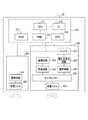
図2は、送電装置10の構成を示す機能ブロック図である。なお、図2において、データの送受信を示す線は実線で示し、電力の供給を示す線は破線で示す。
送電装置10は、制御部110と、無線送信部120と、無線受信部130と、AC電源140と、電源供給部150とを含む。
制御部110は、送電装置10の各部を制御するための構成である。制御部110は、CPU111と、ROM112と、RAM113と、HDD114と、UI115とを含む。制御部110は、無線送信部120及び無線受信部130と内部バスで信号を送受信可能に接続される。
CPU111は、様々なデータを処理し、送電装置10を制御する。ROM112は、不揮発性の記憶媒体であり、CPU111が実行するブートプログラム等を記憶する。RAM113は、揮発性の記憶媒体であり、CPU111が使用するデータやプログラム等を一時的に記憶する。
HDD114は、不揮発性の記憶媒体であり、CPU111が実行するOSやアプリケーションプログラム(コンピュータプログラム)等を記憶する。すなわち、HDD114には、本発明の実施形態にかかる制御方法(後述)を実行するためのコンピュータプログラムが、コンピュータ読取り可能な形式で格納される。
UI115は、使用者に様々な情報を表示し、使用者から様々な指示を受け付ける。UI115は、画像などを表示できる表示デバイスと、使用者が指示を入力するための操作デバイスを含む。表示デバイスは、たとえば液晶表示パネルなど、文字や画像を表示可能な表示デバイスが適用される。操作デバイスは、各種釦や、表示デバイスと一体に構成されるタッチパネルなどが適用される。
CPU111は、HDD114に格納されるコンピュータプログラムを読み出し、RAM113に展開して実行する。これにより、CPU111は、送電装置10の各部を制御する。そして、後述する処理(本発明の実施形態にかかる制御方法)が実現する。FIG. 2 is a functional block diagram illustrating a configuration of the
The
The
The
The
The
The
無線送信部120は、電力を受電装置20へ無線で送信するための構成である。無線送信部120は、通信回路121と、送電回路122と、ダイプレクサー123と、送電コイル124とを含む。
通信回路121は、通信を行うための変調信号を生成する。
送電回路122は、電力を送信するための変調信号を生成する。
ダイプレクサー123は、通信回路121が生成した変調信号と送電回路122が生成した変調信号とを合成する。
送電コイル124は、ダイプレクサー123が合成した変調信号を、受電装置20へ無線で送信する。
無線受信部130は、受電装置20からデータを無線で受信するための構成である。無線受信部130は、受電コイル131と、受信回路132と、復調回路133と、伝搬時間測定回路134と、受信レベル検知回路135と、伝搬距離算出回路136とを含む。
受電コイル131は、通信を行うための変調信号を受電装置20から無線で受信する。
受信回路132は、受電コイル131が無線で受信した変調信号を受信する。
復調回路133は、受信回路132が受信した変調信号を復調する。
伝搬時間測定回路134は、復調回路133が変調した信号から、受電装置20から送信された無線信号が送電装置10に到達するまでの伝搬時間を測定する。
受信レベル検知回路135は、受信回路132からアナログ信号を受信し、無線信号の受信レベル(例えば、受信電力レベル)を検知する。
伝搬距離算出回路136は、伝搬時間測定回路134が測定した伝搬時間と、受信レベル検知回路135が測定した受信レベルとから、送電装置10と受電装置20の距離を算出する。The
The
The
The
The
The
The
The receiving
The
The propagation
The reception
The propagation
AC電源140は、交流電圧を送電コイル124と電源供給部150に供給する。
電源供給部150は、AC電源140が供給する交流電圧を直流電圧へ変換し、直流電圧を制御部110と、無線送信部120と、無線受信部130とに供給する。The
The
図3は、受電装置20の構成を示す機能ブロック図である。なお、図3において、データの送受信を示す線は実線で示し、電力の供給を示す線は破線で示す。
受電装置20は、制御部210と、無線送信部220と、無線受信部230とを含む。FIG. 3 is a functional block diagram illustrating a configuration of the
The
制御部210は、受電装置20の各部を制御するための構成である。制御部210は、CPU211と、ROM212と、RAM213と、HDD214と、UI215とを含む。制御部210は、無線送信部220及び無線受信部230と、内部バスで信号を送受信可能に接続される。
CPU211は、様々なデータを処理して、受電装置20を制御する。
ROM212は、不揮発性の記憶媒体であり、CPU211が実行するブートプログラム等を記憶する。
RAM213は、揮発性の記憶媒体であり、CPU211が使用するデータやプログラム等を一時的に記憶する。
HDD214は、不揮発性の記憶媒体であり、CPU211が実行するOSやアプリケーションプログラム(コンピュータプログラム)等を記憶する。すなわち、HDD214には、受電装置20を制御するためのコンピュータプログラムが格納されている。
UI215は、CPU211による制御にしたがって、使用者に様々な情報を表示し、使用者から様々な指示を受け付ける。UI215は、所定の情報を表示できる表示デバイスと、使用者の操作を受け付ける操作デバイスとを有する。
CPU211は、受電装置20を制御するためのコンピュータプログラムをHDD214から読み出し、RAM213に展開して実行する。このようにして、CPU211は、受電装置20の各部を制御する。これにより、後述する処理(本発明の実施形態にかかる制御方法)が実現する。The
The
The
The
The
The
The
無線送信部220は、送電装置10へデータを無線で送信するための構成である。無線送信部220は、通信回路221と、送電コイル222とを含む。
通信回路221は、通信を行うための変調信号を生成する。
送電コイル222は、通信回路221が生成した変調信号を送電装置10へ無線で送信する。The
The
The
無線受信部230は、電力を送電装置10から無線で受信するための構成である。無線受信部230は、受電コイル231と、ダイプレクサー232と、受信回路233と、復調回路234と、整流回路235と、電圧安定化回路236と、バッテリー237とを含む。
受電コイル231は、送電装置10から変調信号を無線で受信する。
ダイプレクサー232は、受電コイル231が受信した変調信号を、通信を行うための変調信号と、電力を送信するための変調信号とに分ける。
受信回路233は、ダイプレクサー232が分けた通信を行うための変調信号を受信する。
復調回路234は、受信回路233が受信した変調信号を復調する。
整流回路235は、ダイプレクサー232により分けられた電力を送信するための変調信号を整流し、直流電圧を生成する。
電圧安定化回路236は、整流回路235が生成した直流電圧を安定化する。
バッテリー237は、電圧安定化回路236が安定化した電圧を受けて、電力を蓄積する。また、バッテリー237は、蓄積した電力を基に、直流電圧を制御部210と、無線送信部220と、無線受信部230とに電力を供給する。The
The
The diplexer 232 divides the modulation signal received by the
The receiving circuit 233 receives a modulated signal for performing communication divided by the diplexer 232.
The demodulation circuit 234 demodulates the modulation signal received by the reception circuit 233.
The rectifier circuit 235 rectifies the modulation signal for transmitting the power divided by the diplexer 232 to generate a DC voltage.
The
The battery 237 receives the voltage stabilized by the
図4は、スーパーフレームの構造を示す図である。本発明の第1の実施形態にかかる無線給電システムにおいては、この様なスーパーフレームを繰り返し用いることによって、無線給電が実現される。
1つのスーパーフレームは、関連付け期間(S101)と、電力伝送準備期間(S102)と、電力伝送期間(S103)とからなる。なお、それぞれの期間の長さは可変である。
S101では、送電装置10が、受電装置20に対してデバイスIDと電力の必要性の確認を行う。デバイスIDと電力の必要性があれば、S102へ移行する。なお、S101からS102へ移行する期間も可変である。
S102では、受電装置20が、送電装置10のデータリクエストによるフレームのレスポンスやアクノリッジを送信することができる。なお、それぞれのレスポンスフレームの長さやアクノリッジフレームの長さは可変である。S102が終了すると、S103へ移行する。なお、S102からS103へ移行する期間も可変である。
S103では、送電装置10が、受電装置20へ電力を伝送する。S103において、受電装置20は、送電装置10からのリクエストフレームがなくても、フレームを送電装置10へ送信することができる。FIG. 4 is a diagram illustrating the structure of a superframe. In the wireless power feeding system according to the first embodiment of the present invention, wireless power feeding is realized by repeatedly using such a superframe.
One superframe includes an association period (S101), a power transmission preparation period (S102), and a power transmission period (S103). Note that the length of each period is variable.
In S <b> 101, the
In S <b> 102, the
In S <b> 103, the
図5は、フレームフォーマットの構造を示す図である。前述したスーパーフレーム内では、図5に示すようなフレームフォーマットのパケットを用いて、無線給電のためのデータ通信が実現される。
フレームヘッダー310は、データ転送時の宛先等を示すものである。フレームヘッダー310は、ID311と、フレームコントロール312と、発信元アドレス313と、行先アドレス314と、シーケンスナンバー315とを含む。
ID311は、無線給電システムでデータ通信を行うときに使われるIDである。
フレームコントロール312は、受電装置20のデータ交換のための情報である。フレームコントロール312は、電力管理3120を含む。電力管理3120は、電力の必要性を確認するためのデータである。
発信元アドレス313は、データ転送時における発信元のアドレスである。
行先アドレス314は、データ転送時における行先のアドレスである。
シーケンスナンバー315は、フレームの番号である。
フレームボディ320は、データ転送時のデータ本体の情報である。フレームボディ320は、ペイロード321と、フレームチェックシーケンス322とを含む。
ペイロード321は、データ本体である。例えば、デバイスID3210がペイロード321に割り当てられる。
フレームチェックシーケンス322は、ペイロード321のエラーチェックを行うデータである。FIG. 5 is a diagram showing the structure of the frame format. In the above-described superframe, data communication for wireless power feeding is realized using a packet having a frame format as shown in FIG.
The
The
The
The
The
The
The
The
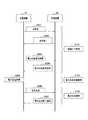
図6は、スーパーフレームにおける送電装置10と受電装置20の間のデータの送受信を示すシーケンス図である。
送電装置10と受電装置20とは、前述したスーパーフレームを用いて、図6に示す様な信号の送受信や電力の送給を行う。これにより、無線給電のためのデータ通信が実現される。
S201において、送電装置10は、受電装置20に対してデバイスIDの要求を送信する。このときは、フレームフォーマットのID311を用いる。受電装置20は、送電装置10からのデバイスIDの要求を受信する。
S202において、受電装置20は、送電装置10に対してデバイスIDを送信する。送電装置10は、受電装置20からデバイスID3210を受け取る。このときは、フレームフォーマットのID311を用いる。
S203において、送電装置10は、受電装置20に電力の必要性を確認する。このときは、フレームフォーマットの電力管理3120を用いる。受電装置20は、送電装置10からの電力の必要性の確認を受信する。そして、受電装置20は、電力の必要があるか否かを判定する。
S204において、受電装置20は、受電装置20に電力の必要があれば、送電装置10へ電力必要の通知を行う。また、S203において、受電装置20は、受電装置20に電力の必要がなければ、送電装置10へ電力不要の通知を行う。このときは、フレームフォーマットの電力管理3120を用いる。送電装置10は、受電装置20からの電力の必要性の回答を受信する。そして、送電装置10は、電力が必要であるとの回答であるか不要であるとの回答であるかを判定する。
S205において、送電装置10は、電力が必要であるとの回答を受信した場合には、電力伝送の準備を行う。
S206において、送電装置10は、受電装置20に電力伝送を行う。受電装置20は、送電装置10から無線により電力の送給を受け、送給された電力を用いてバッテリー237を充電する。
S207において、受電装置20は、バッテリー237がフルになったら、送電装置10へ電力伝送終了の通知を行う。このときは、フレームフォーマットの電力管理3120を用いる。FIG. 6 is a sequence diagram illustrating transmission / reception of data between the
The
In step S <b> 201, the
In step S <b> 202, the
In step S <b> 203, the
In S <b> 204, if the
In S205, the
In S <b> 206, the
In S207, when the battery 237 is full, the
図7は、本発明の第1の実施形態にかかる制御方法の内容を示すフローチャートである。この制御方法を実行するためのコンピュータプログラムは、送電装置10のHDD114と受電装置20のHDD214とにあらかじめ格納されている。そして、送電装置10のCPU111と受電装置20のCPU211がそれぞれこのコンピュータプログラムを読み出して実行する。これにより、送電装置10と受電装置20の各部が制御され、この制御方法が実現する。 FIG. 7 is a flowchart showing the contents of the control method according to the first embodiment of the present invention. A computer program for executing this control method is stored in advance in the
S301では、送電装置10は、工場出荷者などの設定操作に応じて、距離に応じた伝送効率(距離と伝送効率との関係)をROM112またはHDD114に登録する。なお、距離と伝送効率との関係は、あらかじめ調査されており、既知である。
S302では、送電装置10は、通信エリア40内の受電装置20に対して無線通信でポーリングを行い、デバイスIDの確認を行う。受電装置20は、送電装置10の無線通信に応答し無線通信ネットワークでのデバイスIDを返信する。
S303では、送電装置10は、受電装置20が給電エリア30内に存在するか否かの確認を行う。受電装置20が給電エリア30内に存在する場合は、S304へ移行する。受電装置20が給電エリア30に存在しない場合は、S307へ移行する。
S307において、送電装置10は、受電装置20に対して、受電装置20が給電エリア30まで何mの距離にあるかを通知する。送電装置10と受電装置20との距離は、伝搬距離算出回路136が算出する。これにより、受電装置20の使用者に対して、伝送効率の高いエリアへの移動を促す。
S304では、送電装置10は、受電装置20へ電力の伝送が必要かどうかの確認を行う。受電装置20は、電力の伝送が必要であれば電力管理3120に電力伝送の必要性のフラグをたてて、送電装置10へ応答する。In S301, the
In S <b> 302, the
In S <b> 303, the
In step S <b> 307, the
In S <b> 304, the
S305では、送電装置10は、受電装置20が伝送効率の良いエリアにいるかどうかの確認を行う。伝送効率の良いエリアかどうかを判断する方法としては、たとえば次のような方法が適用される。
まず、伝搬時間測定回路134は、復調回路133からの復調信号を用いて、受電装置20から送信された無線信号が送電装置10に到達するまでの伝搬時間を測定する。次に、受信レベル検知回路135は、アナログ受信信号を受け、受信した無線信号の受信レベルを検知する。そして、伝搬距離算出回路136は、伝搬時間測定回路134からの伝搬時間と、受信レベル検知回路135からのレベルを判断して受電装置20と送電装置10との距離を算出する。In S305, the
First, the propagation
図8は、S301において伝送効率の設定をしたときのUI215が表示する画面の一例である。図8に示すように、UI215の表示デバイスは、距離に応じた伝送効率を表示する。この例では、送電装置10を中心に半径1mの範囲が、90%の伝送効率で送電できるエリアに設定される。送電装置10を中心に半径1〜3mの範囲が、60%の伝送効率で送電できるエリアに設定される。送電装置10を中心に半径3〜5mの範囲が、30%の伝送効率で送電できるエリアに設定される。
この例では、第一の設定として、第一の距離表示部1150に距離が0〜1mと入力され、第一の効率表示部1151に伝送効率が90%と入力される。第二の設定として、第二の距離表示部1152に距離が1〜3mと入力され、第二の効率表示部1153に伝送効率が60%と入力される。第三の設定として、第三の距離表示部1154に距離が3〜5mと入力され、第三の効率表示部1155に伝送効率が30%と入力される。
簡易図表示部1156は、1150から1155の設定の簡易図を表示するエリアである。図8に示すように、簡易図表示部1156は、距離に応じた伝送効率を、画像を用いて簡易的に表示する。
また、この例では、90%の伝送効率で送電できるエリア(送電装置10を中心に半径1mの範囲)が、最大伝送効率で電力を送電できるエリアとなる。FIG. 8 is an example of a screen displayed by the
In this example, as a first setting, a distance of 0 to 1 m is input to the first
The simplified
Further, in this example, an area where power can be transmitted with a transmission efficiency of 90% (range of a radius of 1 m centering on the power transmission device 10) is an area where power can be transmitted with the maximum transmission efficiency.
そして、CPU111は、算出した距離と、ステップS301において登録された距離に応じた伝送効率とを照合し、受電装置20が伝送効率の良いエリアにいるかどうか判定する。図8の例を参照すると、受電装置20が伝送効率90%の範囲の距離に存在する場合には、CPU111は、受電装置20が、伝送効率の良いエリア(最大伝送効率の位置)に存在すると判定する。一方、受電装置20が伝送効率60%または30%の範囲の距離に存在する場合には、CPU111は、受電装置20が、伝送効率の良いエリアに存在しない判定する。 Then, the
S306では、送電装置10は、最大伝送効率で電力を伝送できる距離を受電装置20へ通知する。 In S <b> 306, the
図9は、フレームボディ320の一部であるペイロード321の一例を示す図である。
ステップS303において、送電装置10は、受電装置20へ通信距離3211をリクエストし、通信距離3211のデータを受信する。図9(a)は、この場合のペイロード321の構成を示す。この場合には、ペイロード321には、通信距離3211が格納される。
そして、送電装置10は、受電装置20から受け取った通信距離3211から伝送効率3212のデータを受電装置20へ送信する。図9(b)は、この場合のペイロード321の構成を示す。この場合には、ペイロード321には、伝送効率3212が格納される。FIG. 9 is a diagram illustrating an example of a
In step S <b> 303, the
Then, the
<第2の実施形態>
次に、本発明の第2の実施形態について説明する。図10は、本発明の第2の実施形態にかかる送電装置10の機能ブロック図である。
第1の実施形態と第2の実施形態とは、受電装置20との距離を算出する回路の構成が相違する。すなわち、第1の実施形態においては、送電装置10は、伝搬時間測定回路134と、受信レベル検知回路135と、伝搬距離算出回路136とが、送電装置10と受電装置20との距離を算出する。これに対して、第2の実施形態では、送電装置10がリニアセンサー160を有する。そして、このリニアセンサー160が、受電装置20を持った使用者を検知することで、送電装置10と受電装置20との距離を算出し、受電装置20が伝送効率の良いエリアに存在するか否かを判断する。このリニアセンサー160には、公知の各種リニアセンサーが適用できる。そして例えば、図8に示すように3つの設定が登録されている構成であれば、リニアセンサー160は、その設定に応じた3つの距離を判別する。
なお、第2の実施形態においては、伝搬時間測定回路134と、受信レベル検知回路135と、伝搬距離算出回路136とは必要ない。このほかの構成については、第1の実施形態と共通の構成が適用できる。また、制御方法についても、送電装置10において、受電装置20との距離の算出主体と方法とが異なる以外は、第1の実施形態と共通の制御方法が適用できる。したがって、説明は省略する。<Second Embodiment>
Next, a second embodiment of the present invention will be described. FIG. 10 is a functional block diagram of the
The first embodiment is different from the second embodiment in the configuration of a circuit that calculates the distance to the
In the second embodiment, the propagation
<第3の実施形態>
次に、本発明の第3の実施形態について説明する。なお、第1の実施形態または第2の実施形態と共通の構成については同じ符号を付し、説明を省略することがある。
図11は、本発明の第3の実施形態にかかる無線給電システムの構成を示す概念図である。本発明の第3の実施形態にかかる無線給電システムは、第1の実施形態と同様に、送電装置10を含み、1つの送電装置10により複数の受電装置20に磁界共鳴方式により無線で給電できる。
送電装置10は、受電装置20に無線で電力を伝送する。また、送電装置10は、受電装置20との間で給電のために必要なデータ通信も行う。
受電装置20は、送電装置10から無線で電力を受ける。また、受電装置20は、送電装置10との間で給電のために必要なデータ通信も行う。
送電装置10と受電装置20の距離に対応する伝送効率があらかじめ確認されており、送電装置10に登録されている。
位置と伝送効率の登録例として、送電装置10から0〜1mの範囲は伝送効率が90%、1〜2mの範囲は40%、2〜3m以内は10%の例を示す。
給電エリア30は、送電装置10から受電装置20へ給電が実行可能なエリアである。この図11では、送電装置10から3mまでのエリアが給電エリア30である。
通信エリア40は、送電装置10と受電装置20の間においてデータ通信が実行可能なエリアである。図11内では、送電装置10から5mまでのエリアが通信エリア40である。
給電エリア30と通信エリア40の関係は、給電エリア30より通信エリア40の方が広く、給電エリア30は通信エリア40に完全に包含される。<Third Embodiment>
Next, a third embodiment of the present invention will be described. In addition, about the structure which is common in 1st Embodiment or 2nd Embodiment, the same code | symbol may be attached | subjected and description may be abbreviate | omitted.
FIG. 11 is a conceptual diagram showing a configuration of a wireless power feeding system according to the third embodiment of the present invention. As in the first embodiment, the wireless power feeding system according to the third embodiment of the present invention includes the
The
The
The transmission efficiency corresponding to the distance between the
As an example of registration of the position and transmission efficiency, the range of 0 to 1 m from the
The
The
Regarding the relationship between the
図12は、第3の実施形態にかかる送電装置10の構成を示す機能ブロック図である。
送電装置10は、磁界共鳴方式である。送電装置10は、制御部110と、無線送信部120と、無線受信部130と、AC電源140と、電源供給部150と、2次元センサー161とを含む。
第3の実施形態にかかる送電装置10は、第2の実施形態にかかる送電装置10と比較すると、リニアセンサー160が2次元センサー161に置き換わった点で相違する。それ以外は、第3の実施形態と共通の構成が適用される。したがって、説明は省略する。FIG. 12 is a functional block diagram illustrating a configuration of the
The
The
2次元センサー161は、受電装置20を持つ使用者(人間)の位置と距離の検出を行う。2次元センサー161は、たとえば、CPU111とシリアルI/F等で接続される。制御部110は、2次元センサー161が出力するセンサーデータを用いて、使用者の位置を検出する。そして、制御部110は、検出した使用者の位置を、無線送信部120を介して受電装置20へ無線で送信する。 The two-
電源供給部150は、AC電源140が供給する交流電圧を直流電圧へ変換し、直流電圧を制御部110と、無線送信部120と、無線受信部130と、2次元センサー161とに供給する。 The
第3の実施形態にかかる受電装置20は、第1の実施形態との受電装置20と共通の構成が適用される。したがって、説明は省略する。 The
本発明の第3の実施形態にかかる無線給電システムにおいては、送電装置10と受電装置20とがスーパーフレームを使用して通信することにより、無線給電を実現する。第3の実施形態において使用するスーパーフレームの構造およびフレームフォーマットは、第1の実施形態と共通である(図4、図5、図9参照)。したがって、説明は省略する。
また、スーパーフレームを使用した送電装置10と受電装置20との間のデータの送受信のシーケンスも、第1の実施形態と共通である(図6参照)。In the wireless power feeding system according to the third embodiment of the present invention, wireless power feeding is realized by the
In addition, the data transmission / reception sequence between the
ここで、本発明の第3の実施形態にかかる制御方法の内容について、図13を参照して説明する。図13は、本発明の第3の実施形態にかかる制御方法の内容を示すフローチャートである。この制御方法を実行するためのコンピュータプログラムは、送電装置10のHDD114と受電装置20のHDD214にあらかじめ格納されている。送電装置10のCPU111と受電装置20のCPU211は、それぞれこのコンピュータプログラムを読み出して実行することにより、この制御方法が実現する。そして、この制御方法の実行により、受電装置20を持つ使用者に対して、伝送効率の良い位置への移動を促すことができる。 Here, the content of the control method according to the third embodiment of the present invention will be described with reference to FIG. FIG. 13 is a flowchart showing the contents of the control method according to the third embodiment of the present invention. A computer program for executing this control method is stored in advance in the
S401では、送電装置10は、工場出荷者等によるUI215への操作に応じて、距離に応じた伝送効率の設定をROM112またはHDD114に格納する。
図14は、S401において伝送効率の設定をしたときのUI215の表示デバイスの画面の一例である。この例では、送電装置10から0〜1mの範囲は伝送効率が90%、1〜2mの範囲は40%、2〜3m以内は10%の例を示す。
この例では、第一の設定として、第一の距離表示部1150に距離が0〜1mと入力され、第一の効率表示部1151に伝送効率が90%と入力される。第二の設定として、第二の距離表示部1152に距離が1〜2mと入力され、第二の効率表示部1153に伝送効率が40%と入力される。第三の設定として、第三の距離表示部1154に距離が2〜3mと入力され、第三の効率表示部1155に伝送効率が10%と入力される。
なお、図14では、簡易図表示部(図8参照)が設けられない構成を示すが、簡易表示部が設けられる構成であってもよい。In S <b> 401, the
FIG. 14 is an example of a screen of the display device of the
In this example, as a first setting, a distance of 0 to 1 m is input to the first
14 illustrates a configuration in which the simplified diagram display unit (see FIG. 8) is not provided, a configuration in which a simplified display unit is provided may be used.
S402では、送電装置10は、通信エリア40内の受電装置20に対して、伝送効率と距離の表示情報を無線送信する。受電装置20は、受信した情報をUI215の表示デバイスに表示する。図15は、伝送効率と距離の関係の表示の一例を示す。図15に示すように、受電装置20は、S401において設定された伝送効率と距離との関係を、すなわち、0〜1mの範囲においては90%、1〜2mの範囲においては40%、2m以遠においては10%という関係を、UI215の表示デバイスに表示する。図中の数字は、伝送効率を示す。この際、受電効率ごとのエリアを、色を変えて表示することにより、使用者に分かりやすくする。 In S <b> 402, the
S403では、送電装置10は、受電装置20の位置および送電装置10からの距離を、2次元センサー161を用いて検出する。ここで、2次元センサー161について説明する。人感センサーとして、焦電センサーが知られている。焦電センサーは、シングルタイプのセンサー素子を有するものが一般である。シングルタイプのセンサー素子を有する焦電センサーは、広範囲検出が可能であるが、範囲内に人間がいるかいないを検出するのみであり、位置検出精度は低い。最近、改良されたアレイセンサータイプの焦電センサーが使用されるようになってきている。アレイセンサータイプの焦電センサーは、素子がN×Nのアレイ状に並べられたセンサーを有する。アレイセンサータイプの焦電センサーは、広範囲で、位置の高精度の検出が可能である。そこで、本実施形態においては、2次元センサー161に、アレイセンサータイプの焦電センサーが適用されるものとする。
図16は、2次元センサー161としての焦電センサーの外形例を模式的に示す図である。2次元センサー161としての焦電センサーは、センサーレンズ1201を有する。そして、センサーレンズ1201を介して人間の位置および距離を検出する。
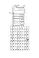
図17は、送電装置10に2次元センサー161が取り付けられている構成の例を示す。図17に示すように、2次元センサー161としての焦電センサーは、送電装置10の前面(受電装置20を持つ使用者が接近する側)の所定の位置に設けられる。これは、受電装置20を持った使用者が送電装置10の前面へ近づいてくることと、焦電センサーの検知範囲が取り付け位置の下方エリアになる特性による。要は、2次元センサー161は、これらの特性を考慮して、送電装置10に接近する使用者の位置および距離を精度よく検出できる位置に取り付けられる構成であればよい。図17においては、素子が8×8に配列される焦電センサーを例に示す。このような焦電センサーによれば、8×8のマトリックス状に分割された検出範囲のいずれに使用者が存在するかを検出できる。なお、分割された各エリアが、いずれの伝送効率の範囲に対応するかは、S301において設定される。例えば、エリア1〜24は距離0〜1mの伝送効率が90%である範囲に対応し、エリア25〜48は距離1〜2mの伝送効率が40%である範囲に対応し、エリア49〜64は距離2m以遠の伝送効率が10%の範囲に対応付けられている。この例の場合には、2次元センサー161としての焦電センサーの検出範囲は、約3m四方になる。また、図17においては、エリア40に使用者が存在すると検出される例を示す。In S <b> 403, the
FIG. 16 is a diagram schematically illustrating an external example of a pyroelectric sensor as the two-
FIG. 17 shows an example of a configuration in which the two-
S404では、送電装置10は、受電装置20を持つ人間(使用者)の位置を、受電装置20へ無線で送信する。受電装置20は、受信した使用者の位置に関する情報を、UI215の表示デバイスに表示する。図18は、使用者の位置に関する情報の表示の一例を示す。例えば、受電装置20は、S402で表示した伝送効率と距離の関係表示に、使用者の位置を重ねて表示する。この例の場合では、エリア40に対応する箇所に、「検知」という表示を行う。これにより、使用者は、自身の位置および送電装置10からの距離を把握することができる。さらに、使用者は、自身が存在する位置における伝送効率を把握することができる。なお、表示の態様は、図17に示す態様に限定されるものではない。例えば、ここでは「検知」という表示を行っているが、この表示に限定されない。要は、このエリアに使用者が存在する表示がされていれば良い。
使用者は、UI215の表示を見て、自身が伝送効率の良い位置に居るかを判断することができる。この例では、使用者は伝送効率40%であるエリア4の位置に存在することを把握できる。このように、第3の実施形態においては、無線給電システムは、受電装置20を持つ使用者に対して、伝送効率の高い位置への移動を促すことができる。In S <b> 404, the
The user can determine whether he / she is in a position with good transmission efficiency by looking at the display of the
受電装置20を持つ使用者が、伝送効率と距離の関係の表示内の現在地を表示する印を見て、伝送効率の良いエリアへ移動したとする。この場合、2次元センサー161は、移動している使用者の位置を連続して検出し、受電装置20に連続的に送信する。受電装置20は、使用者の位置の情報を送電装置10から連続的に受信し、UI215に連続的に表示する。例えば、2次元センサー161は、使用者がエリア40からエリア19に移動したことを検出したとする。そうすると、図19に示すように、受電装置20は、送電装置10から使用者に位置の情報を受信すると、UI215に、使用者がエリア40からエリア19に移動したことを表示する。これにより、使用者は、伝送効率90%のエリアに移動しているのを判断できる。
このような構成によれば、受電装置20を持つ使用者に対して、伝送効率の高い位置への移動を促すことができる。It is assumed that the user having the
According to such a configuration, the user having the
ここで、図13に示す処理を実行するタイミングについて説明する。図20は、送電装置10と受電装置20との間のデータの送受信と電力送信を示すシーケンス図に、図13を参照して説明した制御方法の処理を加えたシーケンス図である。図20に示すように、送電装置10と受電装置20とは、S201,S201でIDの要求と送信を行った後に、S401−S404の処理を実行する。このように、本実施形態においては、あらかじめ、使用者に対して受電装置20を伝送効率の良い位置への移動を促す。その後、送電装置10は、S203からの電力の送信を行う。 Here, the timing for executing the processing shown in FIG. 13 will be described. FIG. 20 is a sequence diagram in which the process of the control method described with reference to FIG. 13 is added to the sequence diagram showing data transmission / reception and power transmission between the
<第4の実施形態>
次に、本発明の第4の実施形態について説明する。図21は、本発明の第4の実施形態における、送電装置10と受電装置20の間でデータの送受信と電力送給を示すシーケンス図である。
第4の実施形態は、第3の実施形態と比較して、「伝送効率の高いエリアへの移動を促す」(S401−S404)のシーケンスが、電力伝送(S206)の開始から電力伝送終了通知(S207)の間に移動している点が相違する。このように、第4の実施形態においては、伝送効率の高いエリアへの移動を促すシーケンス(S401−S404)を、S203−S206後で、電力送信を開始した後に行う。そして、電力伝送が終了するまで、伝送効率の高いエリアへの移動を許可している。
それ以外の構成は、第3の実施形態と共通であるため、説明を省略する。<Fourth Embodiment>
Next, a fourth embodiment of the present invention will be described. FIG. 21 is a sequence diagram showing data transmission / reception and power supply between the
Compared with the third embodiment, in the fourth embodiment, the sequence of “prompt movement to an area with high transmission efficiency” (S401 to S404) is notified from the start of power transmission (S206) to the end of power transmission. The difference is that it moved during (S207). As described above, in the fourth embodiment, the sequence (S401 to S404) that prompts the user to move to an area with high transmission efficiency is performed after the power transmission is started after S203 to S206. And the movement to the area with high transmission efficiency is permitted until electric power transmission is completed.
Since the other configuration is the same as that of the third embodiment, the description thereof is omitted.
以上説明したとおり、本発明の各実施形態にかかる無線電力伝送システムによれば、送電装置は受電装置に対して、電力の伝送効率を通知する。このため、使用者は、受電装置のUIなどを確認することにより、どの位置で給電すれば伝送効率が良いかが分かる。 As described above, according to the wireless power transmission system according to each embodiment of the present invention, the power transmission device notifies the power reception device of the power transmission efficiency. For this reason, the user can know at which position the power supply is good by checking the UI of the power receiving apparatus.
以上、本発明の好ましい実施形態について説明したが、本発明はこれらの実施形態に限定されず、その要旨の範囲内で種々の変形及び変更が可能である。 As mentioned above, although preferable embodiment of this invention was described, this invention is not limited to these embodiment, A various deformation | transformation and change are possible within the range of the summary.
本発明は、以下の処理を実行することによっても実現される。即ち、上述した実施形態の機能を実現するコンピュータ読取り可能なプログラム(ソフトウェア)を、ネットワーク又は各種記録媒体を介してシステム或いは装置に供給し、そのシステム或いは装置のコンピュータ(又はCPUやMPU等)がプログラムを読み出して実行する処理である。この場合、そのプログラム及びプログラムを記憶した記録媒体は本発明を構成することになる。 The present invention is also realized by executing the following processing. That is, a computer-readable program (software) that realizes the functions of the above-described embodiments is supplied to a system or apparatus via a network or various recording media, and a computer (or CPU, MPU, or the like) of the system or apparatus. This is a process of reading and executing a program. In this case, the program and the recording medium storing the program constitute the present invention.
10:送電装置
20:受電装置
30:給電エリア
40:通信エリア10: Power transmission device 20: Power reception device 30: Power feeding area 40: Communication area
Claims (7)
Translated fromJapanese受電装置が前記給電エリア内に存在するか否かを判定する第1の判定手段と、
前記受電装置が前記給電エリア内に存在しないと前記第1の判定手段によって判定された場合に、前記受電装置を前記給電エリア内に移動させることをユーザに促す第1の通知を、前記受電装置に送信する第1の通知手段と、
前記受電装置が前記給電エリア内に存在すると前記第1の判定手段によって判定された場合に、前記受電装置を更に移動させることをユーザに促す第2の通知を、前記受電装置に送信する必要があるか否かを判定する第2の判定手段と、
前記第2の通知を前記受電装置に送信する必要があると前記第2の判定手段によって判定された場合に、前記第2の通知を前記受電装置に送信する第2の通知手段とを備え、
前記第2の通知を前記受電装置に送信する必要がないと前記第2の判定手段によって判定された場合、前記第2の通知手段は、前記第2の通知を前記受電装置に送信しないことを特徴とする給電装置。A power supply device that wirelessly supplies power to apowerreceiving device existing in a power supply area ,
First determination means for determining whether or not a power receiving device exists in the power supply area;
When the first determination unit determines that the power receiving device does not exist in the power feeding area, a first notification that prompts the user to move the power receiving device into the power feeding area is provided. First notification means for transmitting to
When the first determination unit determines that the power receiving device exists in the power supply area, it is necessary to transmit a second notification to the user to further move the power receiving device to the power receiving device. Second determination means for determining whether or not there is;
Second notification means for transmitting the second notification to the power receiving apparatus when the second determination means determines that the second notification needs to betransmitted tothe powerreceiving apparatus;
When the seconddetermination unit determines that the second notification does not need to betransmitted to the power receiving device, the second notification unit does not transmit the second notification to the power receiving device. Characteristic power supply device.
前記特定手段によって特定された距離に基づいて、前記第2の判定手段は、前記第2の通知を前記受電装置に送信する必要があるか否かを判定することを特徴とする請求項1に記載の給電装置。Further comprising a specifying means for specifying a distance between the power feeding device and the powerreceiving device ;
Based on the distance specified by said specifying means,said second determination means, the second notification to claim1, wherein thedetermining whether it is necessary to be transmitted to the power receiving device The power feeding apparatus described.
前記特定手段によって特定された距離が、前記複数のエリアのうち最も伝送効率が良いエリアの外に前記受電装置が存在することを示す場合に、前記第2の判定手段は、前記第2の通知を前記受電装置に送信する必要があると判定し、When the distance specified by the specifying means indicates that the power receiving apparatus exists outside an area having the highest transmission efficiency among the plurality of areas, the second determination means determines that the second notification Is determined to be transmitted to the power receiving device,
前記特定手段によって特定された距離が、前記最も伝送効率が良いエリア内に前記受電装置が存在することを示す場合に、前記第2の判定手段は、前記第2の通知を前記受電装置に送信する必要がないと判定することを特徴とする請求項2に記載の給電装置。When the distance specified by the specifying means indicates that the power receiving apparatus exists in the area with the highest transmission efficiency, the second determination means transmits the second notification to the power receiving apparatus. The power feeding device according to claim 2, wherein it is determined that it is not necessary to perform the operation.
前記複数のエリアのうち最も伝送効率が良いエリアの外に前記受電装置が存在する場合に、前記第2の判定手段は、前記第2の通知を前記受電装置に送信する必要があると判定し、When the power receiving apparatus exists outside the area with the highest transmission efficiency among the plurality of areas, the second determination unit determines that the second notification needs to be transmitted to the power receiving apparatus. ,
前記最も伝送効率が良いエリア内に前記受電装置が存在する場合に、前記第2の判定手段は、前記第2の通知を前記受電装置に送信する必要がないと判定することを特徴とする請求項1に記載の給電装置。The second determination unit determines that the second notification does not need to be transmitted to the power receiving device when the power receiving device exists in the area with the highest transmission efficiency. Item 2. The power feeding device according to Item 1.
前記第2の通知には、前記受電装置から前記最も伝送効率が良いエリアまでの距離が少なくとも含まれることを特徴とする請求項3又は4に記載の給電装置。The first notification includes at least a distance from the power receiving device to the power supply area,
5. Thepower feeding device according to claim 3, wherein the second notificationincludes at least a distance from the power receiving device to thearea with the highest transmission efficiency .
受電装置が前記給電エリア内に存在するか否かを判定する第1の判定ステップと、
前記受電装置が前記給電エリア内に存在しないと前記第1の判定ステップにおいて判定された場合に、前記受電装置を前記給電エリア内に移動させることをユーザに促す第1の通知を、前記受電装置に送信する第1の通知ステップと、
前記受電装置が前記給電エリア内に存在すると前記第1の判定ステップにおいて判定された場合に、前記受電装置を更に移動させることをユーザに促す第2の通知を、前記受電装置に送信する必要があるか否かを判定する第2の判定ステップと、
前記第2の通知を前記受電装置に送信する必要があると前記第2の判定ステップにおいて判定された場合に、前記第2の通知を前記受電装置に送信する第2の通知ステップとを備え、
前記第2の通知を前記受電装置に送信する必要がないと前記第2の判定ステップにおいて判定された場合、前記第2の通知ステップにおいては、前記第2の通知を前記受電装置に送信しないことを特徴とする給電方法。A power supply method for supplying power wirelessly to a power receiving device existing in a power supply area,
A first determination step of determining whether or not a power receiving device exists in the power supply area;
When it is determined in the first determination step that the power receiving device does not exist in the power feeding area, a first notification that prompts the user to move the power receiving device into the power feeding area is provided. A first notification step to send to
When it is determined in the first determination step that the power receiving device is present in the power supply area, it is necessary to transmit to the power receiving device a second notification that prompts the user to move the power receiving device further. A second determination step for determining whether there is,
A second notificationstep of transmitting the second notification to the power receiving device when it is determined in the second determinationstep that the second notification needs to be transmitted to the power receiving device;
If it is determined in the second determination step that the second notification does not need to be transmitted to the power receiving device, the second notification is not transmitted to the power receiving device in the second notification step. A power supply method characterized by the above.
前記給電方法は、
受電装置が前記給電エリア内に存在するか否かを判定する第1の判定ステップと、
前記受電装置が前記給電エリア内に存在しないと前記第1の判定ステップにおいて判定された場合に、前記受電装置を前記給電エリア内に移動させることをユーザに促す第1の通知を、前記受電装置に送信する第1の通知ステップと、
前記受電装置が前記給電エリア内に存在すると前記第1の判定ステップにおいて判定された場合に、前記受電装置を更に移動させることをユーザに促す第2の通知を、前記受電装置に送信する必要があるか否かを判定する第2の判定ステップと、
前記第2の通知を前記受電装置に送信する必要があると前記第2の判定ステップにおいて判定された場合に、前記第2の通知を前記受電装置に送信する第2の通知ステップとを備え、
前記第2の通知を前記受電装置に送信する必要がないと前記第2の判定ステップにおいて判定された場合、前記第2の通知ステップにおいては、前記第2の通知を前記受電装置に送信しないことを特徴とするプログラム。A program for causing a computer to execute a power feeding method for wirelessly supplying power to a power receiving device existing in a power feeding area,
The power supply method is:
A first determination step of determining whether or not a power receiving device exists in the power supply area;
When it is determined in the first determination step that the power receiving device does not exist in the power feeding area, a first notification that prompts the user to move the power receiving device into the power feeding area is provided. A first notification step to send to
When it is determined in the first determination step that the power receiving device is present in the power supply area, it is necessary to transmit to the power receiving device a second notification that prompts the user to move the power receiving device further. A second determination step for determining whether there is,
A second notificationstep of transmitting the second notification to the power receiving device when it is determined in the second determinationstep that the second notification needs to be transmitted to the power receiving device;
If it is determined in the second determination step that the second notification does not need to be transmitted to the power receiving device, the second notification is not transmitted to the power receiving device in the second notification step. A program characterized by
Priority Applications (3)
| Application Number | Priority Date | Filing Date | Title |
|---|---|---|---|
| JP2013014350AJP6128861B2 (en) | 2013-01-29 | 2013-01-29 | Power supply apparatus, power supply method, and program |
| CN201410030178.0ACN103972992B (en) | 2013-01-29 | 2014-01-22 | power transmission device and control method thereof |
| US14/165,962US9692249B2 (en) | 2013-01-29 | 2014-01-28 | Power supply system, power transmission device, power receiving device, method for controlling power transmission device, method for controlling power receiving device, and program |
Applications Claiming Priority (1)
| Application Number | Priority Date | Filing Date | Title |
|---|---|---|---|
| JP2013014350AJP6128861B2 (en) | 2013-01-29 | 2013-01-29 | Power supply apparatus, power supply method, and program |
Publications (3)
| Publication Number | Publication Date |
|---|---|
| JP2014147219A JP2014147219A (en) | 2014-08-14 |
| JP2014147219A5 JP2014147219A5 (en) | 2016-03-17 |
| JP6128861B2true JP6128861B2 (en) | 2017-05-17 |
Family
ID=51222127
Family Applications (1)
| Application Number | Title | Priority Date | Filing Date |
|---|---|---|---|
| JP2013014350AActiveJP6128861B2 (en) | 2013-01-29 | 2013-01-29 | Power supply apparatus, power supply method, and program |
Country Status (3)
| Country | Link |
|---|---|
| US (1) | US9692249B2 (en) |
| JP (1) | JP6128861B2 (en) |
| CN (1) | CN103972992B (en) |
Families Citing this family (194)
| Publication number | Priority date | Publication date | Assignee | Title |
|---|---|---|---|---|
| US9948135B2 (en) | 2015-09-22 | 2018-04-17 | Energous Corporation | Systems and methods for identifying sensitive objects in a wireless charging transmission field |
| US10243414B1 (en) | 2014-05-07 | 2019-03-26 | Energous Corporation | Wearable device with wireless power and payload receiver |
| US9368020B1 (en) | 2013-05-10 | 2016-06-14 | Energous Corporation | Off-premises alert system and method for wireless power receivers in a wireless power network |
| US9900057B2 (en) | 2012-07-06 | 2018-02-20 | Energous Corporation | Systems and methods for assigning groups of antenas of a wireless power transmitter to different wireless power receivers, and determining effective phases to use for wirelessly transmitting power using the assigned groups of antennas |
| US10218227B2 (en) | 2014-05-07 | 2019-02-26 | Energous Corporation | Compact PIFA antenna |
| US10224982B1 (en) | 2013-07-11 | 2019-03-05 | Energous Corporation | Wireless power transmitters for transmitting wireless power and tracking whether wireless power receivers are within authorized locations |
| US9871398B1 (en) | 2013-07-01 | 2018-01-16 | Energous Corporation | Hybrid charging method for wireless power transmission based on pocket-forming |
| US9867062B1 (en) | 2014-07-21 | 2018-01-09 | Energous Corporation | System and methods for using a remote server to authorize a receiving device that has requested wireless power and to determine whether another receiving device should request wireless power in a wireless power transmission system |
| US10063105B2 (en) | 2013-07-11 | 2018-08-28 | Energous Corporation | Proximity transmitters for wireless power charging systems |
| US9853692B1 (en) | 2014-05-23 | 2017-12-26 | Energous Corporation | Systems and methods for wireless power transmission |
| US10050462B1 (en) | 2013-08-06 | 2018-08-14 | Energous Corporation | Social power sharing for mobile devices based on pocket-forming |
| US9787103B1 (en) | 2013-08-06 | 2017-10-10 | Energous Corporation | Systems and methods for wirelessly delivering power to electronic devices that are unable to communicate with a transmitter |
| US10090886B1 (en) | 2014-07-14 | 2018-10-02 | Energous Corporation | System and method for enabling automatic charging schedules in a wireless power network to one or more devices |
| US10211680B2 (en) | 2013-07-19 | 2019-02-19 | Energous Corporation | Method for 3 dimensional pocket-forming |
| US10199835B2 (en) | 2015-12-29 | 2019-02-05 | Energous Corporation | Radar motion detection using stepped frequency in wireless power transmission system |
| US10063064B1 (en) | 2014-05-23 | 2018-08-28 | Energous Corporation | System and method for generating a power receiver identifier in a wireless power network |
| US9887584B1 (en) | 2014-08-21 | 2018-02-06 | Energous Corporation | Systems and methods for a configuration web service to provide configuration of a wireless power transmitter within a wireless power transmission system |
| US10193396B1 (en) | 2014-05-07 | 2019-01-29 | Energous Corporation | Cluster management of transmitters in a wireless power transmission system |
| US10211674B1 (en) | 2013-06-12 | 2019-02-19 | Energous Corporation | Wireless charging using selected reflectors |
| US10008889B2 (en) | 2014-08-21 | 2018-06-26 | Energous Corporation | Method for automatically testing the operational status of a wireless power receiver in a wireless power transmission system |
| US9793758B2 (en) | 2014-05-23 | 2017-10-17 | Energous Corporation | Enhanced transmitter using frequency control for wireless power transmission |
| US9954374B1 (en) | 2014-05-23 | 2018-04-24 | Energous Corporation | System and method for self-system analysis for detecting a fault in a wireless power transmission Network |
| US9838083B2 (en) | 2014-07-21 | 2017-12-05 | Energous Corporation | Systems and methods for communication with remote management systems |
| US9876648B2 (en) | 2014-08-21 | 2018-01-23 | Energous Corporation | System and method to control a wireless power transmission system by configuration of wireless power transmission control parameters |
| US10291055B1 (en) | 2014-12-29 | 2019-05-14 | Energous Corporation | Systems and methods for controlling far-field wireless power transmission based on battery power levels of a receiving device |
| US10141791B2 (en) | 2014-05-07 | 2018-11-27 | Energous Corporation | Systems and methods for controlling communications during wireless transmission of power using application programming interfaces |
| US10256657B2 (en) | 2015-12-24 | 2019-04-09 | Energous Corporation | Antenna having coaxial structure for near field wireless power charging |
| US9843213B2 (en) | 2013-08-06 | 2017-12-12 | Energous Corporation | Social power sharing for mobile devices based on pocket-forming |
| US9859797B1 (en) | 2014-05-07 | 2018-01-02 | Energous Corporation | Synchronous rectifier design for wireless power receiver |
| US10263432B1 (en) | 2013-06-25 | 2019-04-16 | Energous Corporation | Multi-mode transmitter with an antenna array for delivering wireless power and providing Wi-Fi access |
| US9991741B1 (en) | 2014-07-14 | 2018-06-05 | Energous Corporation | System for tracking and reporting status and usage information in a wireless power management system |
| US9143000B2 (en) | 2012-07-06 | 2015-09-22 | Energous Corporation | Portable wireless charging pad |
| US9973021B2 (en) | 2012-07-06 | 2018-05-15 | Energous Corporation | Receivers for wireless power transmission |
| US20140008993A1 (en) | 2012-07-06 | 2014-01-09 | DvineWave Inc. | Methodology for pocket-forming |
| US9876379B1 (en) | 2013-07-11 | 2018-01-23 | Energous Corporation | Wireless charging and powering of electronic devices in a vehicle |
| US9843201B1 (en) | 2012-07-06 | 2017-12-12 | Energous Corporation | Wireless power transmitter that selects antenna sets for transmitting wireless power to a receiver based on location of the receiver, and methods of use thereof |
| US10992187B2 (en) | 2012-07-06 | 2021-04-27 | Energous Corporation | System and methods of using electromagnetic waves to wirelessly deliver power to electronic devices |
| US10199849B1 (en) | 2014-08-21 | 2019-02-05 | Energous Corporation | Method for automatically testing the operational status of a wireless power receiver in a wireless power transmission system |
| US9912199B2 (en) | 2012-07-06 | 2018-03-06 | Energous Corporation | Receivers for wireless power transmission |
| US10128699B2 (en) | 2014-07-14 | 2018-11-13 | Energous Corporation | Systems and methods of providing wireless power using receiver device sensor inputs |
| US9831718B2 (en) | 2013-07-25 | 2017-11-28 | Energous Corporation | TV with integrated wireless power transmitter |
| US9923386B1 (en) | 2012-07-06 | 2018-03-20 | Energous Corporation | Systems and methods for wireless power transmission by modifying a number of antenna elements used to transmit power waves to a receiver |
| US9824815B2 (en) | 2013-05-10 | 2017-11-21 | Energous Corporation | Wireless charging and powering of healthcare gadgets and sensors |
| US9899873B2 (en) | 2014-05-23 | 2018-02-20 | Energous Corporation | System and method for generating a power receiver identifier in a wireless power network |
| US10312715B2 (en) | 2015-09-16 | 2019-06-04 | Energous Corporation | Systems and methods for wireless power charging |
| US9847679B2 (en) | 2014-05-07 | 2017-12-19 | Energous Corporation | System and method for controlling communication between wireless power transmitter managers |
| US10224758B2 (en) | 2013-05-10 | 2019-03-05 | Energous Corporation | Wireless powering of electronic devices with selective delivery range |
| US9438045B1 (en) | 2013-05-10 | 2016-09-06 | Energous Corporation | Methods and systems for maximum power point transfer in receivers |
| US9882430B1 (en) | 2014-05-07 | 2018-01-30 | Energous Corporation | Cluster management of transmitters in a wireless power transmission system |
| US9124125B2 (en) | 2013-05-10 | 2015-09-01 | Energous Corporation | Wireless power transmission with selective range |
| US10124754B1 (en) | 2013-07-19 | 2018-11-13 | Energous Corporation | Wireless charging and powering of electronic sensors in a vehicle |
| US10075008B1 (en) | 2014-07-14 | 2018-09-11 | Energous Corporation | Systems and methods for manually adjusting when receiving electronic devices are scheduled to receive wirelessly delivered power from a wireless power transmitter in a wireless power network |
| US10230266B1 (en) | 2014-02-06 | 2019-03-12 | Energous Corporation | Wireless power receivers that communicate status data indicating wireless power transmission effectiveness with a transmitter using a built-in communications component of a mobile device, and methods of use thereof |
| US10223717B1 (en) | 2014-05-23 | 2019-03-05 | Energous Corporation | Systems and methods for payment-based authorization of wireless power transmission service |
| US9847677B1 (en) | 2013-10-10 | 2017-12-19 | Energous Corporation | Wireless charging and powering of healthcare gadgets and sensors |
| US9893768B2 (en) | 2012-07-06 | 2018-02-13 | Energous Corporation | Methodology for multiple pocket-forming |
| US11502551B2 (en) | 2012-07-06 | 2022-11-15 | Energous Corporation | Wirelessly charging multiple wireless-power receivers using different subsets of an antenna array to focus energy at different locations |
| US9893555B1 (en) | 2013-10-10 | 2018-02-13 | Energous Corporation | Wireless charging of tools using a toolbox transmitter |
| US9939864B1 (en) | 2014-08-21 | 2018-04-10 | Energous Corporation | System and method to control a wireless power transmission system by configuration of wireless power transmission control parameters |
| US10186913B2 (en) | 2012-07-06 | 2019-01-22 | Energous Corporation | System and methods for pocket-forming based on constructive and destructive interferences to power one or more wireless power receivers using a wireless power transmitter including a plurality of antennas |
| US9887739B2 (en) | 2012-07-06 | 2018-02-06 | Energous Corporation | Systems and methods for wireless power transmission by comparing voltage levels associated with power waves transmitted by antennas of a plurality of antennas of a transmitter to determine appropriate phase adjustments for the power waves |
| US9893554B2 (en) | 2014-07-14 | 2018-02-13 | Energous Corporation | System and method for providing health safety in a wireless power transmission system |
| US10270261B2 (en) | 2015-09-16 | 2019-04-23 | Energous Corporation | Systems and methods of object detection in wireless power charging systems |
| US10063106B2 (en) | 2014-05-23 | 2018-08-28 | Energous Corporation | System and method for a self-system analysis in a wireless power transmission network |
| US10206185B2 (en) | 2013-05-10 | 2019-02-12 | Energous Corporation | System and methods for wireless power transmission to an electronic device in accordance with user-defined restrictions |
| US10211682B2 (en) | 2014-05-07 | 2019-02-19 | Energous Corporation | Systems and methods for controlling operation of a transmitter of a wireless power network based on user instructions received from an authenticated computing device powered or charged by a receiver of the wireless power network |
| US9941707B1 (en) | 2013-07-19 | 2018-04-10 | Energous Corporation | Home base station for multiple room coverage with multiple transmitters |
| US9906065B2 (en) | 2012-07-06 | 2018-02-27 | Energous Corporation | Systems and methods of transmitting power transmission waves based on signals received at first and second subsets of a transmitter's antenna array |
| US10141768B2 (en) | 2013-06-03 | 2018-11-27 | Energous Corporation | Systems and methods for maximizing wireless power transfer efficiency by instructing a user to change a receiver device's position |
| US9966765B1 (en) | 2013-06-25 | 2018-05-08 | Energous Corporation | Multi-mode transmitter |
| US9252628B2 (en) | 2013-05-10 | 2016-02-02 | Energous Corporation | Laptop computer as a transmitter for wireless charging |
| US9876394B1 (en) | 2014-05-07 | 2018-01-23 | Energous Corporation | Boost-charger-boost system for enhanced power delivery |
| US10103582B2 (en) | 2012-07-06 | 2018-10-16 | Energous Corporation | Transmitters for wireless power transmission |
| US10965164B2 (en) | 2012-07-06 | 2021-03-30 | Energous Corporation | Systems and methods of wirelessly delivering power to a receiver device |
| US10291066B1 (en) | 2014-05-07 | 2019-05-14 | Energous Corporation | Power transmission control systems and methods |
| US9859756B2 (en) | 2012-07-06 | 2018-01-02 | Energous Corporation | Transmittersand methods for adjusting wireless power transmission based on information from receivers |
| US9899861B1 (en) | 2013-10-10 | 2018-02-20 | Energous Corporation | Wireless charging methods and systems for game controllers, based on pocket-forming |
| US10038337B1 (en) | 2013-09-16 | 2018-07-31 | Energous Corporation | Wireless power supply for rescue devices |
| US10148097B1 (en) | 2013-11-08 | 2018-12-04 | Energous Corporation | Systems and methods for using a predetermined number of communication channels of a wireless power transmitter to communicate with different wireless power receivers |
| US10128693B2 (en) | 2014-07-14 | 2018-11-13 | Energous Corporation | System and method for providing health safety in a wireless power transmission system |
| US9853458B1 (en) | 2014-05-07 | 2017-12-26 | Energous Corporation | Systems and methods for device and power receiver pairing |
| US10205239B1 (en) | 2014-05-07 | 2019-02-12 | Energous Corporation | Compact PIFA antenna |
| US10992185B2 (en) | 2012-07-06 | 2021-04-27 | Energous Corporation | Systems and methods of using electromagnetic waves to wirelessly deliver power to game controllers |
| US9812890B1 (en) | 2013-07-11 | 2017-11-07 | Energous Corporation | Portable wireless charging pad |
| US12057715B2 (en) | 2012-07-06 | 2024-08-06 | Energous Corporation | Systems and methods of wirelessly delivering power to a wireless-power receiver device in response to a change of orientation of the wireless-power receiver device |
| US9806564B2 (en) | 2014-05-07 | 2017-10-31 | Energous Corporation | Integrated rectifier and boost converter for wireless power transmission |
| US10439448B2 (en) | 2014-08-21 | 2019-10-08 | Energous Corporation | Systems and methods for automatically testing the communication between wireless power transmitter and wireless power receiver |
| US9941754B2 (en) | 2012-07-06 | 2018-04-10 | Energous Corporation | Wireless power transmission with selective range |
| US9882427B2 (en) | 2013-05-10 | 2018-01-30 | Energous Corporation | Wireless power delivery using a base station to control operations of a plurality of wireless power transmitters |
| US9859757B1 (en) | 2013-07-25 | 2018-01-02 | Energous Corporation | Antenna tile arrangements in electronic device enclosures |
| US9941747B2 (en) | 2014-07-14 | 2018-04-10 | Energous Corporation | System and method for manually selecting and deselecting devices to charge in a wireless power network |
| US9891669B2 (en) | 2014-08-21 | 2018-02-13 | Energous Corporation | Systems and methods for a configuration web service to provide configuration of a wireless power transmitter within a wireless power transmission system |
| US9825674B1 (en) | 2014-05-23 | 2017-11-21 | Energous Corporation | Enhanced transmitter that selects configurations of antenna elements for performing wireless power transmission and receiving functions |
| US10090699B1 (en) | 2013-11-01 | 2018-10-02 | Energous Corporation | Wireless powered house |
| US10381880B2 (en) | 2014-07-21 | 2019-08-13 | Energous Corporation | Integrated antenna structure arrays for wireless power transmission |
| US20150326070A1 (en) | 2014-05-07 | 2015-11-12 | Energous Corporation | Methods and Systems for Maximum Power Point Transfer in Receivers |
| US9819230B2 (en) | 2014-05-07 | 2017-11-14 | Energous Corporation | Enhanced receiver for wireless power transmission |
| US9538382B2 (en) | 2013-05-10 | 2017-01-03 | Energous Corporation | System and method for smart registration of wireless power receivers in a wireless power network |
| US9419443B2 (en) | 2013-05-10 | 2016-08-16 | Energous Corporation | Transducer sound arrangement for pocket-forming |
| US9866279B2 (en) | 2013-05-10 | 2018-01-09 | Energous Corporation | Systems and methods for selecting which power transmitter should deliver wireless power to a receiving device in a wireless power delivery network |
| US9537357B2 (en) | 2013-05-10 | 2017-01-03 | Energous Corporation | Wireless sound charging methods and systems for game controllers, based on pocket-forming |
| US10103552B1 (en) | 2013-06-03 | 2018-10-16 | Energous Corporation | Protocols for authenticated wireless power transmission |
| US10003211B1 (en) | 2013-06-17 | 2018-06-19 | Energous Corporation | Battery life of portable electronic devices |
| US10021523B2 (en) | 2013-07-11 | 2018-07-10 | Energous Corporation | Proximity transmitters for wireless power charging systems |
| US9979440B1 (en) | 2013-07-25 | 2018-05-22 | Energous Corporation | Antenna tile arrangements configured to operate as one functional unit |
| US9935482B1 (en) | 2014-02-06 | 2018-04-03 | Energous Corporation | Wireless power transmitters that transmit at determined times based on power availability and consumption at a receiving mobile device |
| US10075017B2 (en) | 2014-02-06 | 2018-09-11 | Energous Corporation | External or internal wireless power receiver with spaced-apart antenna elements for charging or powering mobile devices using wirelessly delivered power |
| US10158257B2 (en) | 2014-05-01 | 2018-12-18 | Energous Corporation | System and methods for using sound waves to wirelessly deliver power to electronic devices |
| US9966784B2 (en) | 2014-06-03 | 2018-05-08 | Energous Corporation | Systems and methods for extending battery life of portable electronic devices charged by sound |
| US10153653B1 (en) | 2014-05-07 | 2018-12-11 | Energous Corporation | Systems and methods for using application programming interfaces to control communications between a transmitter and a receiver |
| US10170917B1 (en) | 2014-05-07 | 2019-01-01 | Energous Corporation | Systems and methods for managing and controlling a wireless power network by establishing time intervals during which receivers communicate with a transmitter |
| US9973008B1 (en) | 2014-05-07 | 2018-05-15 | Energous Corporation | Wireless power receiver with boost converters directly coupled to a storage element |
| US9800172B1 (en) | 2014-05-07 | 2017-10-24 | Energous Corporation | Integrated rectifier and boost converter for boosting voltage received from wireless power transmission waves |
| US10153645B1 (en) | 2014-05-07 | 2018-12-11 | Energous Corporation | Systems and methods for designating a master power transmitter in a cluster of wireless power transmitters |
| US9876536B1 (en) | 2014-05-23 | 2018-01-23 | Energous Corporation | Systems and methods for assigning groups of antennas to transmit wireless power to different wireless power receivers |
| US10068703B1 (en) | 2014-07-21 | 2018-09-04 | Energous Corporation | Integrated miniature PIFA with artificial magnetic conductor metamaterials |
| US10116143B1 (en) | 2014-07-21 | 2018-10-30 | Energous Corporation | Integrated antenna arrays for wireless power transmission |
| US9871301B2 (en) | 2014-07-21 | 2018-01-16 | Energous Corporation | Integrated miniature PIFA with artificial magnetic conductor metamaterials |
| US9917477B1 (en) | 2014-08-21 | 2018-03-13 | Energous Corporation | Systems and methods for automatically testing the communication between power transmitter and wireless receiver |
| US9965009B1 (en) | 2014-08-21 | 2018-05-08 | Energous Corporation | Systems and methods for assigning a power receiver to individual power transmitters based on location of the power receiver |
| US10033198B2 (en)* | 2014-09-11 | 2018-07-24 | Cpg Technologies, Llc | Frequency division multiplexing for wireless power providers |
| US10122415B2 (en) | 2014-12-27 | 2018-11-06 | Energous Corporation | Systems and methods for assigning a set of antennas of a wireless power transmitter to a wireless power receiver based on a location of the wireless power receiver |
| US9893535B2 (en) | 2015-02-13 | 2018-02-13 | Energous Corporation | Systems and methods for determining optimal charging positions to maximize efficiency of power received from wirelessly delivered sound wave energy |
| US12283828B2 (en) | 2015-09-15 | 2025-04-22 | Energous Corporation | Receiver devices configured to determine location within a transmission field |
| US9906275B2 (en) | 2015-09-15 | 2018-02-27 | Energous Corporation | Identifying receivers in a wireless charging transmission field |
| US10523033B2 (en) | 2015-09-15 | 2019-12-31 | Energous Corporation | Receiver devices configured to determine location within a transmission field |
| US9941752B2 (en) | 2015-09-16 | 2018-04-10 | Energous Corporation | Systems and methods of object detection in wireless power charging systems |
| US10158259B1 (en) | 2015-09-16 | 2018-12-18 | Energous Corporation | Systems and methods for identifying receivers in a transmission field by transmitting exploratory power waves towards different segments of a transmission field |
| US9871387B1 (en) | 2015-09-16 | 2018-01-16 | Energous Corporation | Systems and methods of object detection using one or more video cameras in wireless power charging systems |
| US9893538B1 (en) | 2015-09-16 | 2018-02-13 | Energous Corporation | Systems and methods of object detection in wireless power charging systems |
| US10008875B1 (en) | 2015-09-16 | 2018-06-26 | Energous Corporation | Wireless power transmitter configured to transmit power waves to a predicted location of a moving wireless power receiver |
| US10211685B2 (en) | 2015-09-16 | 2019-02-19 | Energous Corporation | Systems and methods for real or near real time wireless communications between a wireless power transmitter and a wireless power receiver |
| US10199850B2 (en)* | 2015-09-16 | 2019-02-05 | Energous Corporation | Systems and methods for wirelessly transmitting power from a transmitter to a receiver by determining refined locations of the receiver in a segmented transmission field associated with the transmitter |
| US11710321B2 (en) | 2015-09-16 | 2023-07-25 | Energous Corporation | Systems and methods of object detection in wireless power charging systems |
| US10186893B2 (en) | 2015-09-16 | 2019-01-22 | Energous Corporation | Systems and methods for real time or near real time wireless communications between a wireless power transmitter and a wireless power receiver |
| US10778041B2 (en) | 2015-09-16 | 2020-09-15 | Energous Corporation | Systems and methods for generating power waves in a wireless power transmission system |
| US10027168B2 (en) | 2015-09-22 | 2018-07-17 | Energous Corporation | Systems and methods for generating and transmitting wireless power transmission waves using antennas having a spacing that is selected by the transmitter |
| US10135295B2 (en) | 2015-09-22 | 2018-11-20 | Energous Corporation | Systems and methods for nullifying energy levels for wireless power transmission waves |
| US10153660B1 (en) | 2015-09-22 | 2018-12-11 | Energous Corporation | Systems and methods for preconfiguring sensor data for wireless charging systems |
| US10128686B1 (en)* | 2015-09-22 | 2018-11-13 | Energous Corporation | Systems and methods for identifying receiver locations using sensor technologies |
| US10050470B1 (en) | 2015-09-22 | 2018-08-14 | Energous Corporation | Wireless power transmission device having antennas oriented in three dimensions |
| US10033222B1 (en) | 2015-09-22 | 2018-07-24 | Energous Corporation | Systems and methods for determining and generating a waveform for wireless power transmission waves |
| US10020678B1 (en) | 2015-09-22 | 2018-07-10 | Energous Corporation | Systems and methods for selecting antennas to generate and transmit power transmission waves |
| US10135294B1 (en) | 2015-09-22 | 2018-11-20 | Energous Corporation | Systems and methods for preconfiguring transmission devices for power wave transmissions based on location data of one or more receivers |
| US10333332B1 (en) | 2015-10-13 | 2019-06-25 | Energous Corporation | Cross-polarized dipole antenna |
| US10734717B2 (en) | 2015-10-13 | 2020-08-04 | Energous Corporation | 3D ceramic mold antenna |
| US9853485B2 (en) | 2015-10-28 | 2017-12-26 | Energous Corporation | Antenna for wireless charging systems |
| US9899744B1 (en) | 2015-10-28 | 2018-02-20 | Energous Corporation | Antenna for wireless charging systems |
| US10135112B1 (en) | 2015-11-02 | 2018-11-20 | Energous Corporation | 3D antenna mount |
| US10063108B1 (en) | 2015-11-02 | 2018-08-28 | Energous Corporation | Stamped three-dimensional antenna |
| US10027180B1 (en) | 2015-11-02 | 2018-07-17 | Energous Corporation | 3D triple linear antenna that acts as heat sink |
| US11863001B2 (en) | 2015-12-24 | 2024-01-02 | Energous Corporation | Near-field antenna for wireless power transmission with antenna elements that follow meandering patterns |
| US10038332B1 (en) | 2015-12-24 | 2018-07-31 | Energous Corporation | Systems and methods of wireless power charging through multiple receiving devices |
| US10116162B2 (en) | 2015-12-24 | 2018-10-30 | Energous Corporation | Near field transmitters with harmonic filters for wireless power charging |
| US10320446B2 (en) | 2015-12-24 | 2019-06-11 | Energous Corporation | Miniaturized highly-efficient designs for near-field power transfer system |
| US10256677B2 (en) | 2016-12-12 | 2019-04-09 | Energous Corporation | Near-field RF charging pad with adaptive loading to efficiently charge an electronic device at any position on the pad |
| US10079515B2 (en) | 2016-12-12 | 2018-09-18 | Energous Corporation | Near-field RF charging pad with multi-band antenna element with adaptive loading to efficiently charge an electronic device at any position on the pad |
| US10027159B2 (en) | 2015-12-24 | 2018-07-17 | Energous Corporation | Antenna for transmitting wireless power signals |
| US10008886B2 (en) | 2015-12-29 | 2018-06-26 | Energous Corporation | Modular antennas with heat sinks in wireless power transmission systems |
| JP6752641B2 (en)* | 2016-06-28 | 2020-09-09 | 日置電機株式会社 | measuring device |
| US10923954B2 (en) | 2016-11-03 | 2021-02-16 | Energous Corporation | Wireless power receiver with a synchronous rectifier |
| KR102185600B1 (en) | 2016-12-12 | 2020-12-03 | 에너저스 코포레이션 | A method of selectively activating antenna zones of a near field charging pad to maximize transmitted wireless power |
| US10439442B2 (en) | 2017-01-24 | 2019-10-08 | Energous Corporation | Microstrip antennas for wireless power transmitters |
| US10680319B2 (en) | 2017-01-06 | 2020-06-09 | Energous Corporation | Devices and methods for reducing mutual coupling effects in wireless power transmission systems |
| US10389161B2 (en) | 2017-03-15 | 2019-08-20 | Energous Corporation | Surface mount dielectric antennas for wireless power transmitters |
| US11011942B2 (en) | 2017-03-30 | 2021-05-18 | Energous Corporation | Flat antennas having two or more resonant frequencies for use in wireless power transmission systems |
| US10511097B2 (en) | 2017-05-12 | 2019-12-17 | Energous Corporation | Near-field antennas for accumulating energy at a near-field distance with minimal far-field gain |
| US11462949B2 (en) | 2017-05-16 | 2022-10-04 | Wireless electrical Grid LAN, WiGL Inc | Wireless charging method and system |
| US12074452B2 (en) | 2017-05-16 | 2024-08-27 | Wireless Electrical Grid Lan, Wigl Inc. | Networked wireless charging system |
| US12074460B2 (en) | 2017-05-16 | 2024-08-27 | Wireless Electrical Grid Lan, Wigl Inc. | Rechargeable wireless power bank and method of using |
| US10848853B2 (en) | 2017-06-23 | 2020-11-24 | Energous Corporation | Systems, methods, and devices for utilizing a wire of a sound-producing device as an antenna for receipt of wirelessly delivered power |
| US10122219B1 (en) | 2017-10-10 | 2018-11-06 | Energous Corporation | Systems, methods, and devices for using a battery as a antenna for receiving wirelessly delivered power from radio frequency power waves |
| US11342798B2 (en) | 2017-10-30 | 2022-05-24 | Energous Corporation | Systems and methods for managing coexistence of wireless-power signals and data signals operating in a same frequency band |
| US10615647B2 (en) | 2018-02-02 | 2020-04-07 | Energous Corporation | Systems and methods for detecting wireless power receivers and other objects at a near-field charging pad |
| US11159057B2 (en) | 2018-03-14 | 2021-10-26 | Energous Corporation | Loop antennas with selectively-activated feeds to control propagation patterns of wireless power signals |
| US11515732B2 (en) | 2018-06-25 | 2022-11-29 | Energous Corporation | Power wave transmission techniques to focus wirelessly delivered power at a receiving device |
| JP7218109B2 (en)* | 2018-06-28 | 2023-02-06 | 日置電機株式会社 | measuring device |
| US11437735B2 (en) | 2018-11-14 | 2022-09-06 | Energous Corporation | Systems for receiving electromagnetic energy using antennas that are minimally affected by the presence of the human body |
| US11539243B2 (en) | 2019-01-28 | 2022-12-27 | Energous Corporation | Systems and methods for miniaturized antenna for wireless power transmissions |
| EP3921945A1 (en) | 2019-02-06 | 2021-12-15 | Energous Corporation | Systems and methods of estimating optimal phases to use for individual antennas in an antenna array |
| US12155231B2 (en) | 2019-04-09 | 2024-11-26 | Energous Corporation | Asymmetric spiral antennas for wireless power transmission and reception |
| WO2021055898A1 (en) | 2019-09-20 | 2021-03-25 | Energous Corporation | Systems and methods for machine learning based foreign object detection for wireless power transmission |
| WO2021055899A1 (en) | 2019-09-20 | 2021-03-25 | Energous Corporation | Systems and methods of protecting wireless power receivers using multiple rectifiers and establishing in-band communications using multiple rectifiers |
| US11381118B2 (en) | 2019-09-20 | 2022-07-05 | Energous Corporation | Systems and methods for machine learning based foreign object detection for wireless power transmission |
| WO2021055901A1 (en) | 2019-09-20 | 2021-03-25 | Energous Corporation | Asymmetric spiral antennas with parasitic elements for wireless power transmission |
| CN114731061A (en) | 2019-09-20 | 2022-07-08 | 艾诺格思公司 | Classifying and detecting foreign objects using a power amplifier controller integrated circuit in a wireless power transmission system |
| US11355966B2 (en) | 2019-12-13 | 2022-06-07 | Energous Corporation | Charging pad with guiding contours to align an electronic device on the charging pad and efficiently transfer near-field radio-frequency energy to the electronic device |
| US10985617B1 (en) | 2019-12-31 | 2021-04-20 | Energous Corporation | System for wirelessly transmitting energy at a near-field distance without using beam-forming control |
| US11799324B2 (en) | 2020-04-13 | 2023-10-24 | Energous Corporation | Wireless-power transmitting device for creating a uniform near-field charging area |
| US11469629B2 (en) | 2020-08-12 | 2022-10-11 | Energous Corporation | Systems and methods for secure wireless transmission of power using unidirectional communication signals from a wireless-power-receiving device |
| US12306285B2 (en) | 2020-12-01 | 2025-05-20 | Energous Corporation | Systems and methods for using one or more sensors to detect and classify objects in a keep-out zone of a wireless-power transmission field, and antennas with integrated sensor arrangements |
| US12101725B2 (en) | 2021-09-22 | 2024-09-24 | Apple Inc. | Transmission power control |
| US11916398B2 (en) | 2021-12-29 | 2024-02-27 | Energous Corporation | Small form-factor devices with integrated and modular harvesting receivers, and shelving-mounted wireless-power transmitters for use therewith |
| US12142939B2 (en) | 2022-05-13 | 2024-11-12 | Energous Corporation | Integrated wireless-power-transmission platform designed to operate in multiple bands, and multi-band antennas for use therewith |
Family Cites Families (13)
| Publication number | Priority date | Publication date | Assignee | Title |
|---|---|---|---|---|
| WO2006037316A2 (en)* | 2004-10-06 | 2006-04-13 | Inventis Gmbh | Processor-controlled receiving unit for navigation data and method for transmitting and processing navigation data |
| KR100971748B1 (en) | 2007-11-30 | 2010-07-22 | 정춘길 | Short range wireless power transfer system |
| JP2009261156A (en)* | 2008-04-17 | 2009-11-05 | Sony Corp | Radio communication apparatus, power supply method, program and radio communication system |
| WO2010035321A1 (en)* | 2008-09-25 | 2010-04-01 | トヨタ自動車株式会社 | Power supply system and electric vehicle |
| JP2010183814A (en)* | 2009-02-09 | 2010-08-19 | Toyota Industries Corp | Non-contact power transmitter |
| JP5365306B2 (en)* | 2009-03-31 | 2013-12-11 | 富士通株式会社 | Wireless power supply system |
| KR101438294B1 (en)* | 2010-02-10 | 2014-09-04 | 후지쯔 가부시끼가이샤 | Resonance frequency control method, power transmission device, and power reception device for magnetic-resonant-coupling type power transmission system |
| CN101950999A (en)* | 2010-09-21 | 2011-01-19 | 宇龙计算机通信科技(深圳)有限公司 | Wireless charging method, wireless charging receiving device and mobile terminal |
| US9184633B2 (en)* | 2011-02-03 | 2015-11-10 | Denso Corporation | Non-contact power supply control device, non-contact power supply system, and non-contact power charge system |
| JP5743590B2 (en)* | 2011-02-18 | 2015-07-01 | 本田技研工業株式会社 | Electric car |
| JP5817267B2 (en)* | 2011-07-07 | 2015-11-18 | 富士ゼロックス株式会社 | Control device, image processing device |
| JP2013070580A (en)* | 2011-09-26 | 2013-04-18 | Sony Corp | Power receiving device, power transmitting device, wireless power transfer system, and wireless power transfer method |
| JP5772535B2 (en)* | 2011-11-18 | 2015-09-02 | トヨタ自動車株式会社 | Power transmission system and vehicle |
- 2013
- 2013-01-29JPJP2013014350Apatent/JP6128861B2/enactiveActive
- 2014
- 2014-01-22CNCN201410030178.0Apatent/CN103972992B/ennot_activeExpired - Fee Related
- 2014-01-28USUS14/165,962patent/US9692249B2/ennot_activeExpired - Fee Related
Also Published As
| Publication number | Publication date |
|---|---|
| JP2014147219A (en) | 2014-08-14 |
| CN103972992A (en) | 2014-08-06 |
| CN103972992B (en) | 2016-09-14 |
| US20140210281A1 (en) | 2014-07-31 |
| US9692249B2 (en) | 2017-06-27 |
Similar Documents
| Publication | Publication Date | Title |
|---|---|---|
| JP6128861B2 (en) | Power supply apparatus, power supply method, and program | |
| JP6188351B2 (en) | Power supply apparatus, power supply apparatus control method, and program | |
| JP6108915B2 (en) | Power receiving apparatus, control method thereof, and program | |
| TW201027873A (en) | Radio frequency charging system and method | |
| JP2010130729A (en) | Charging equipment, transmission equipment, and noncontact charging system | |
| KR20160003457A (en) | Image forming apparatus, position guiding method thereof and image forming system | |
| CN103246488A (en) | Mobile terminal and print instruction program | |
| US20140306547A1 (en) | Power transmission device, power transmission method, and storage medium | |
| US20190196757A1 (en) | Image processing system and mobile terminal device | |
| EP4293873A1 (en) | Power transmission device, control method of power transmission device, and program | |
| JP5854643B2 (en) | Information processing apparatus, control method, and program | |
| WO2018221515A1 (en) | Terminal device for position measurement, computer program, and system | |
| JP2015073339A (en) | Power transmission device, power reception device, control method of the same devices, and program | |
| JP6188605B2 (en) | Device registration program | |
| JP2018164123A (en) | Terminal management apparatus and terminal management system | |
| JP2019022090A (en) | Sensor device | |
| US20140177804A1 (en) | X-ray imaging apparatus | |
| JP2015152565A (en) | Electronics | |
| JP2016057829A (en) | Printing system and printing method | |
| JP5797058B2 (en) | IMAGING SYSTEM, IMAGING SYSTEM CONTROL METHOD, CONTROL DEVICE, AND DETECTION DEVICE | |
| EP3410786A1 (en) | Wireless communication apparatus, host terminal, and wireless communication system | |
| JP2015002658A (en) | Device and method for power transmission, and program | |
| JP6869041B2 (en) | Power transmission equipment, control methods and programs for power transmission equipment | |
| JP6094035B2 (en) | Image transmission apparatus, image transmission system, and program | |
| JP2017106752A (en) | Portable terminal device, information processing method, and program |
Legal Events
| Date | Code | Title | Description |
|---|---|---|---|
| A521 | Request for written amendment filed | Free format text:JAPANESE INTERMEDIATE CODE: A523 Effective date:20160129 | |
| A621 | Written request for application examination | Free format text:JAPANESE INTERMEDIATE CODE: A621 Effective date:20160129 | |
| A977 | Report on retrieval | Free format text:JAPANESE INTERMEDIATE CODE: A971007 Effective date:20161024 | |
| A131 | Notification of reasons for refusal | Free format text:JAPANESE INTERMEDIATE CODE: A131 Effective date:20161108 | |
| A521 | Request for written amendment filed | Free format text:JAPANESE INTERMEDIATE CODE: A523 Effective date:20161209 | |
| A131 | Notification of reasons for refusal | Free format text:JAPANESE INTERMEDIATE CODE: A131 Effective date:20170221 | |
| A521 | Request for written amendment filed | Free format text:JAPANESE INTERMEDIATE CODE: A523 Effective date:20170224 | |
| TRDD | Decision of grant or rejection written | ||
| A01 | Written decision to grant a patent or to grant a registration (utility model) | Free format text:JAPANESE INTERMEDIATE CODE: A01 Effective date:20170314 | |
| A61 | First payment of annual fees (during grant procedure) | Free format text:JAPANESE INTERMEDIATE CODE: A61 Effective date:20170411 | |
| R151 | Written notification of patent or utility model registration | Ref document number:6128861 Country of ref document:JP Free format text:JAPANESE INTERMEDIATE CODE: R151 |