JP6128341B2 - Cooker - Google Patents
CookerDownload PDFInfo
- Publication number
- JP6128341B2 JP6128341B2JP2014506031AJP2014506031AJP6128341B2JP 6128341 B2JP6128341 B2JP 6128341B2JP 2014506031 AJP2014506031 AJP 2014506031AJP 2014506031 AJP2014506031 AJP 2014506031AJP 6128341 B2JP6128341 B2JP 6128341B2
- Authority
- JP
- Japan
- Prior art keywords
- steam
- heating chamber
- cooking
- wall surface
- heating
- Prior art date
- Legal status (The legal status is an assumption and is not a legal conclusion. Google has not performed a legal analysis and makes no representation as to the accuracy of the status listed.)
- Active
Links
Images


Classifications
- A—HUMAN NECESSITIES
- A47—FURNITURE; DOMESTIC ARTICLES OR APPLIANCES; COFFEE MILLS; SPICE MILLS; SUCTION CLEANERS IN GENERAL
- A47J—KITCHEN EQUIPMENT; COFFEE MILLS; SPICE MILLS; APPARATUS FOR MAKING BEVERAGES
- A47J27/00—Cooking-vessels
- A47J27/04—Cooking-vessels for cooking food in steam; Devices for extracting fruit juice by means of steam ; Vacuum cooking vessels
- F—MECHANICAL ENGINEERING; LIGHTING; HEATING; WEAPONS; BLASTING
- F24—HEATING; RANGES; VENTILATING
- F24C—DOMESTIC STOVES OR RANGES ; DETAILS OF DOMESTIC STOVES OR RANGES, OF GENERAL APPLICATION
- F24C15/00—Details
- F24C15/32—Arrangements of ducts for hot gases, e.g. in or around baking ovens
- F24C15/322—Arrangements of ducts for hot gases, e.g. in or around baking ovens with forced circulation
- F24C15/327—Arrangements of ducts for hot gases, e.g. in or around baking ovens with forced circulation with air moisturising
- A—HUMAN NECESSITIES
- A47—FURNITURE; DOMESTIC ARTICLES OR APPLIANCES; COFFEE MILLS; SPICE MILLS; SUCTION CLEANERS IN GENERAL
- A47J—KITCHEN EQUIPMENT; COFFEE MILLS; SPICE MILLS; APPARATUS FOR MAKING BEVERAGES
- A47J27/00—Cooking-vessels
- A47J27/04—Cooking-vessels for cooking food in steam; Devices for extracting fruit juice by means of steam ; Vacuum cooking vessels
- A47J2027/043—Cooking-vessels for cooking food in steam; Devices for extracting fruit juice by means of steam ; Vacuum cooking vessels for cooking food in steam
- H—ELECTRICITY
- H05—ELECTRIC TECHNIQUES NOT OTHERWISE PROVIDED FOR
- H05B—ELECTRIC HEATING; ELECTRIC LIGHT SOURCES NOT OTHERWISE PROVIDED FOR; CIRCUIT ARRANGEMENTS FOR ELECTRIC LIGHT SOURCES, IN GENERAL
- H05B6/00—Heating by electric, magnetic or electromagnetic fields
- H05B6/64—Heating using microwaves
- H05B6/647—Aspects related to microwave heating combined with other heating techniques
- H05B6/6473—Aspects related to microwave heating combined with other heating techniques combined with convection heating
- H05B6/6479—Aspects related to microwave heating combined with other heating techniques combined with convection heating using steam
Landscapes
- Engineering & Computer Science (AREA)
- Chemical & Material Sciences (AREA)
- Combustion & Propulsion (AREA)
- Mechanical Engineering (AREA)
- General Engineering & Computer Science (AREA)
- Food Science & Technology (AREA)
- Electric Ovens (AREA)
- Commercial Cooking Devices (AREA)
- Cookers (AREA)
Description
Translated fromJapanese本発明は、加熱室内に供給される蒸気を発生させる蒸気発生部を有する加熱調理器に関する。 The present invention relates to a cooking device having a steam generating section that generates steam supplied into a heating chamber.
加熱室内を循環する高温気流に飽和水蒸気を供給し、食品表面での水蒸気の凝縮伝熱作用による加熱の高速性と、ビタミン、ミネラルや美味成分などの流出を抑制する利点を利用した加熱調理装置が従来知られている(特許文献1等参照)。 Saturated steam is supplied to the high-temperature airflow circulating in the heating chamber, and the cooking equipment uses the advantages of high-speed heating by the condensation heat transfer action of steam on the food surface and the advantage of suppressing the outflow of vitamins, minerals, delicious ingredients, etc. Is conventionally known (see, for example, Patent Document 1).
ここで、従来の加熱調理装置100の正面図を図7(A)に示し、従来の加熱調理装置100の内部構成を側方から示す断面図を図7(B)に示す。図7(A)、(B)に示すように、この従来の加熱調理装置100は、加熱室101の左内壁面および右内壁面に、前後方向へ延びる上レール102が形成される。それぞれの上レール102の上には、上調理皿103が着脱可能に載置される。加熱室101の左内壁面および右内壁面には、前後方向へ延びる下レール104が形成される。それぞれの下レール104上には下調理皿105が着脱可能に載置される。 Here, a front view of the
加熱室101の後面には、上吐出口106および下吐出口107が形成されている。また、加熱室101の後面には吸入口108が形成されている。加熱室101内の空気が吸入口108より吸入されて、吸入された空気がヒータにて加熱された後、上吐出口106および下吐出口107を通して加熱された空気が加熱室101へ吐出される。 An
加熱室101の左内壁面における上レール102と下レール104との間には、蒸気ガイド109が固定され、蒸気ガイド109には複数のガイド部110が形成されている。これらガイド部110は、図示しない蒸気生成ユニットの蒸気口に接続されており、左右方向に水平に延びる円筒状を有している。ガイド部110は、蒸気生成ユニットの蒸気口から供給される蒸気の流通方向を案内する。蒸気口から供給された蒸気は、ガイド部110の内周面に沿って案内され、上レール102と下レール104との間の高さを水平方向へ真直ぐに流れるように、加熱室101内に供給される。 A
このような構成を有する従来の加熱調理装置100では、上レール102と下レール104との間に蒸気ガイド109が設けられている。そのため、蒸気ガイド109のガイド部110から加熱室101内へ吹き出された蒸気の一部分が、上レール102に支持される上調理皿103の上方へ流出する。その結果、上調理皿103の下面と下調理皿105の上面と間の空間における蒸気濃度が低下し易い。この空間が所望の蒸気濃度となるのには、蒸気が上方へ流出する分、時間を要する。また、下調理皿105よりも上方のこのような空間を短時間で所望の蒸気濃度とするには、蒸気生成ユニットの消費電力を増大させる必要がある。また、蒸気ガイド109は、円筒状に形成した複数のガイド部110によって構成されるため、部品点数、組み立て工数が増え、製品コストが増大する。 In the
本発明は上記状況に鑑みてなされたもので、その目的は、製品コストの増大および消費電力の増大を抑制しながら、加熱室内において調理に求められる蒸気濃度の調理領域を短時間で得ることができる加熱調理器を提供することにある。 The present invention has been made in view of the above situation, and its object is to obtain a cooking region having a steam concentration required for cooking in a heating chamber in a short time while suppressing an increase in product cost and an increase in power consumption. It is in providing the heating cooker which can be performed.
本発明の加熱調理器は、前面が開口された加熱室を内側に形成する内箱及び前記内箱の外方を覆う外箱を有する筐体と、前記加熱室を開閉する扉と、前記加熱室の互いに対向する内壁面に設けられ、上下方向における複数段の支持位置にて調理皿の両端を支持する調理皿支持部と、水を収容する水タンクと、前記筐体の側壁において前記内箱と前記外箱との間に設けられ、前記水タンクから供給される水を用いて蒸気を生成する蒸気発生部と、前記蒸気発生部と前記加熱室とを蒸気通路で接続する蒸気噴出部と、を備え、前記蒸気噴出部は、前記加熱室の内壁面に設けられた一つの凹部と、前記蒸気発生部にて生成された蒸気を前記加熱室内に噴出圧力の低下を抑制しながら供給する手段と、を備え、前記手段は、前記蒸気発生部の上部に設けられた一つの供給口と、前記凹部内の前記加熱室の内壁面に設けられた一つの吐出口と、一端が前記供給口に接続され他端が前記吐出口に接続された蒸気通路を構成する一本の蒸気接続パイプと、を備え、前記吐出口は、前記調理皿支持部の最上段の支持位置に支持される前記調理皿と前記加熱室の天井面との間の空間に面する一方の内壁面に設けられた前記凹部内において前記加熱室の内壁面から突出して設けられているものである。
The cooking device of the present invention includes a housing having an inner box that forms a heating chamber having an open front surface and an outer box that covers the outside of the inner box, a door that opens and closes the heating chamber, and the heating Provided on inner wall surfaces facing each other in the chamber and supporting both ends of the cooking plate at a plurality of support positions in the vertical direction, a water tank for containing water, and the inner wall at the side wall of the casing. A steam generating section that is provided between the box and the outer box and generates steam using water supplied from the water tank; and a steam ejection section that connects the steam generating section and the heating chamber through a steam passage And the steam ejection section suppliesone recess provided on the inner wall surface of the heating chamber and the steam generated in the steam generation section while suppressing a decrease in ejection pressure into the heating chamber.and meansfor, the said means, set at the top of the steam generating unit Configuration and one supply port which is, and one discharge port provided on the inner wall surface of the heating chamberof the recess, the steam path with one end the other end is connected to the supply port being connected to said discharge port The steam outlet pipe faces the space between the cooking plate supported at the uppermost support position of the cooking plate support and the ceiling surface of the heating chamber. In therecessed part provided in one inner wall surface, itprotrudes from the inner wall surface of the heating chamber .
本発明に係る加熱調理器によれば、製品コストの増大および消費電力の増大を抑制しながら、加熱室内において調理に求められる蒸気濃度の調理領域を短時間で得ることができる。 According to the cooking device according to the present invention, a cooking region having a steam concentration required for cooking in a heating chamber can be obtained in a short time while suppressing an increase in product cost and power consumption.
第1の発明の加熱調理器は、前面が開口された加熱室を内側に形成する内箱及び前記内箱の外方を覆う外箱を有する筐体と、前記加熱室を開閉する扉と、前記加熱室の互いに対向する内壁面に設けられ、上下方向における複数段の支持位置にて調理皿の両端を支持する調理皿支持部と、水を収容する水タンクと、前記筐体の側壁において前記内箱と前記外箱との間に設けられ、前記水タンクから供給される水を用いて蒸気を生成する蒸気発生部と、前記蒸気発生部と前記加熱室とを蒸気通路で接続する蒸気噴出部と、を備え、前記蒸気噴出部は、前記加熱室の内壁面に設けられた一つの凹部と、前記蒸気発生部にて生成された蒸気を前記加熱室内に噴出圧力の低下を抑制しながら供給する手段と、を備え、前記手段は、前記蒸気発生部の上部に設けられた一つの供給口と、前記凹部内の前記加熱室の内壁面に設けられた一つの吐出口と、一端が前記供給口に接続され他端が前記吐出口に接続された蒸気通路を構成する一本の蒸気接続パイプと、を備え、前記吐出口は、前記調理皿支持部の最上段の支持位置に支持される前記調理皿と前記加熱室の天井面との間の空間に面する一方の内壁面に設けられた前記凹部内において前記加熱室の内壁面から突出して設けられているものである。
A heating cooker according to a first aspect of the present invention includes a housing having an inner box that forms a heating chamber having an open front surface and an outer box that covers the outside of the inner box, a door that opens and closes the heating chamber, On the inner wall surfaces facing each other in the heating chamber, in a cooking tray support section that supports both ends of the cooking tray at a plurality of support positions in the vertical direction, a water tank that contains water, and a side wall of the housing Steam that is provided between the inner box and the outer box and generates steam using water supplied from the water tank, and steam that connects the steam generator and the heating chamber through a steam passage. A steam discharge section, and the steam spray section suppresses a decrease in the pressure of spray into the heating chamber withone recess provided on the inner wall surface of the heating chamber and the steam generated in the steam generation section.and means for supplying with said means, the top of the steam generating unit And one feed opening provided, and one discharge port provided on the inner wall surface of the heating chamberof the recess, the steam path with one end the other end is connected to the supply port being connected to said discharge port A steam connection pipe that constitutes the surface, and the discharge port faces a space between the cooking plate supported by the uppermost support position of the cooking plate support and the ceiling surface of the heating chamber. In theconcave portion provided on the one inner wallsurface, the projection is provided so as to protrude from the inner wall surface of the heating chamber .
このような構成とすることにより、調理皿支持部の最上段の支持位置に支持される調理皿と加熱室の天井面との間の空間に対して、蒸気噴出部の吐出口を通して蒸気を供給することができ、供給された蒸気が上方へ逃げることもない。よって、蒸気発生に伴う消費電力の増大を抑制しながら、加熱室内において調理に求められる蒸気濃度の調理領域を短時間で得ることができる。また、蒸気噴出部は1つの吐出口を備えるという簡素な構成により実現できるため、製品コストの増大も抑制できる。 With this configuration, steam is supplied to the space between the cooking pan supported at the uppermost support position of the cooking pan support section and the ceiling surface of the heating chamber through the outlet of the steam ejection section. The supplied steam does not escape upward. Therefore, the cooking area | region of the vapor | steam density | concentration calculated | required for cooking in a heating chamber can be obtained in a short time, suppressing the increase in the power consumption accompanying steam generation. Moreover, since a vapor | steam ejection part can be implement | achieved by the simple structure of providing one discharge port, the increase in product cost can also be suppressed.
第2の発明の加熱調理器は、第1の発明の加熱調理器において、前記調理皿と前記加熱室の天井面との間の空間は、蒸気を含んだ高温空気を貯留する実質的な閉塞空間である。このような構成とすることにより、最上段の他の段に調理皿が支持される場合や、調理皿が使用されない場合に比べ、調理領域が短時間で蒸気に満たされる。The cooking device of the second invention is the cooking device of the first invention,wherein the space between the cooking pan and the ceiling surface of the heating chamber is substantially closed to store hot air containing steam. It is space . By setting it as such a structure, compared with the case where a cooking plate is supported by the other stage of theuppermost stage, or the case where a cooking plate is not used, a cooking area | region is satisfy | filled with steam in a short time .
以下、本発明の実施の形態について、図面を参照しながら説明する。なお、この実施の形態によって本発明が限定されるものではない。 Hereinafter, embodiments of the present invention will be described with reference to the drawings. Note that the present invention is not limited to the embodiments.
(実施の形態)
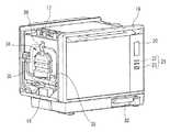
図1は、本発明に係る実施の形態の加熱調理器において扉が開かれた状態を示す斜視図であり、図2は、図1の加熱調理器において筐体の外箱を除いた状態にて加熱調理器を蒸気発生部側から見た斜視図であり、図3は、図2の加熱調理器の扉が開かれた状態を示す斜視図である。(Embodiment)
FIG. 1 is a perspective view showing a state where a door is opened in a heating cooker according to an embodiment of the present invention, and FIG. 2 is a state where an outer box of a housing is removed from the heating cooker of FIG. Fig. 3 is a perspective view of the heating cooker as seen from the steam generation unit side, and Fig. 3 is a perspective view showing a state where the door of the heating cooker of Fig. 2 is opened.
図1に示すように、本実施の形態の加熱調理器10は、前面11に開口部12を有する矩形箱状の筐体13を備える。筐体13は、内方に加熱室14を形成する内箱15と、内箱15の外方を覆う外箱16とを備える。筐体13の内方に形成される加熱室14に対して、開口部12を通して調理物などの加熱対象物が出し入れされる。 As shown in FIG. 1, the
図2に示すように、筐体13において、加熱室14の上方には上部電気室17が設けられ、加熱室14の下方には下部電気室18が設けられる。筐体13の開口部12の下方には扉19が水平方向の回転中心で開閉自在に取り付けられる。扉19が垂直状態となるように回転操作されることで加熱室14が閉鎖され、水平状態となるように回転操作されることで加熱室14が開放される。 As shown in FIG. 2, in the
正面視した扉19の一方の側方には、表示部20および操作部21が配置されている。正面視した場合に、操作部21の一部が加熱室14の内部空間に重なるように扉19に操作部21が配置されている。加熱調理器10の調理動作を操作するための各種の操作スイッチ22や調理スイッチ23が操作部21に設けられている。 A
下部電気室18には、マイクロ波を発生させるマグネトロン(図示せず)と、このマグネトロンに電力を供給するマグネトロン駆動電源(図示せず)と、マイクロ波発生動作の制御などを行う制御部等(図示せず)とが設けられる。 The lower
加熱室14の奥面24(図1参照)と外箱16との間には熱源である加熱ヒータ(コンベクションヒータ(図示せず))が設けられている。コンベクションヒータは、加熱室14の奥面24と外箱16とに挟まれた収容空間に配置されている。コンベクションヒータの中央側には循環ファン(図示しない)が設けられる。加熱室14の奥面24には吸気孔25および排気孔26が形成されており、循環ファンが回転駆動されることで、加熱室14の空気は吸気孔25から吸引され、コンベクションヒータによって加熱されて排気孔26から再び加熱室14へ戻る。これにより、調理物を均一に高温加熱する。 A heater (convection heater (not shown)) as a heat source is provided between the back surface 24 (see FIG. 1) of the
なお、加熱室14の上面側には、熱源として上部加熱ヒータが追加的に設けられていてもよい。上部加熱ヒータは、発熱することによって、加熱室14の調理物を輻射熱により加熱処理する。 An upper heater may be additionally provided on the upper surface side of the
筐体13の内箱15における互いに対向する内壁面には、上下方向における複数段の支持位置にて調理皿の両端を支持する調理皿支持部が設けられている。具体的には、図1および図3に示すように、加熱室14の開口部12を挟む一対の平行な内箱15の内壁面である左側内壁面27(図1参照)および右側内壁面28(図3参照)には、前後方向へ延在する上段レール29、中段レール30、下段レール31が調理皿支持部として設けられている。上段レール29、下段レール31、中段レール30のそれぞれには、調理皿32の両端が着脱可能に載置される。つまり、調理皿32は、左側内壁面27および右側内壁面28にレールを介して両端が支持されることで、加熱室14における上下多段支持位置(上段、中段、下段支持位置)の任意段(任意の支持位置)に支持される。加熱調理器10において、調理皿32は少なくとも一枚が備えられており、複数枚の調理皿32が備えられる場合であっても良い。 On the inner wall surfaces of the
加熱調理器10は、加熱室14内に蒸気を供給するための構成として、水を収容する水タンク33と、水タンク33から供給される水を用いて蒸気を生成する蒸気発生部34と、蒸気発生部34にて生成された蒸気を加熱室14内に噴出させて供給する蒸気噴出部35とを備えている。 The
図2に示すように、水タンク33は下部電気室18の下方に備えられる。蒸気発生部34は、筐体13の内箱15と外箱16との間に設けられており、水タンク33の水がポンプモータ(図示せず)によって蒸気発生部34に供給されて、蒸気発生部34にて蒸気が生成される。蒸気噴出部35は、蒸気発生部34と加熱室14とを接続する蒸気通路である蒸気接続パイプ36と、加熱室14の左側内壁面27に開口孔として設けられ、蒸気接続パイプ36の一端が接続される吐出口35Aとを備える。蒸気発生部34にて生成された蒸気は、蒸気接続パイプ36を通って吐出口35Aより加熱室14内に噴出して供給される。これにより、調理物に対する蒸気加熱が行われる。 As shown in FIG. 2, the
下部電気室18の制御部には、CPU、ROM、RAMを有する制御回路が設けられ、制御回路は調理制御および注水制御を行う。この制御回路には、加熱室14内の温度を検出する庫内温度センサ(図示せず)と、蒸気発生部34にて生成される蒸気温度を検出する蒸気温度センサ(図示せず)が接続される。制御回路は、庫内温度センサからの出力信号に基づいて加熱室14の庫内温度を検出し、蒸気温度センサからの出力信号に基づいて蒸気発生部34の温度を検出する。また、制御回路には、上述した操作スイッチ22や調理スイッチ23が接続される。これら複数のスイッチは、使用者が調理メニュー、調理温度、予熱の有無等の調理情報を入力するためのものとなる。制御回路は、複数のスイッチの操作内容に応じ、調理メニュー、調理温度、予熱の有無等の調理情報を検出する機能を有している。 The control unit of the lower
また、制御回路は、循環ファン、コンベクションヒータ、上部加熱ヒータ、マグネトロン、循環ファン、ポンプモータ(いずれも図示せず)を、調理情報の検出結果に基づいて個別に駆動制御する機能を有する。さらに、商用電源に接続される主電源部から制御回路に電力が供給され、マグネトロン、コンベクションヒータ、上部加熱ヒータ、蒸気発生部34等の加熱電力が許容電力値を超えないように、制御回路はこれら各部への電力配分を制御する。 The control circuit has a function of individually driving and controlling the circulation fan, the convection heater, the upper heating heater, the magnetron, the circulation fan, and the pump motor (all not shown) based on the detection result of the cooking information. Furthermore, the control circuit is configured so that power is supplied to the control circuit from the main power supply unit connected to the commercial power supply, and the heating power of the magnetron, the convection heater, the upper heating heater, the
図4は図3に示した蒸気発生部34の拡大図であり、図5は図1に示した蒸気噴出部35の拡大図であり、図6は調理皿32が中段支持位置に取り付けられた状態の加熱調理器10の斜視図である。 4 is an enlarged view of the
蒸気発生部34は、軽量で熱伝導性の高いアルミダイカスト製のスチームボイラ37を有する。スチームボイラ37には、水タンク33から水が供給される給水管38と、スチームボイラ37内の水が排水されるサイフォン排水管39とが接続される。また、スチームボイラ37には、生成された蒸気を供給する一つの供給口37Aが設けられており、この供給口37Aには、蒸気噴出部35の蒸気接続パイプ36の他端が接続される。図4に示すように、スチームボイラ37の内方には、蒸気生成用ヒータ37Bが設けられ、蒸気生成用ヒータ37Bは給水管38より供給された水を沸騰させ、体積膨張した蒸気(例えば、飽和蒸気)を、供給口37Aを通して蒸気接続パイプ36へ送り出す。 The
蒸気噴出部35において、蒸気接続パイプ36の先端は吐出口35Aに接続される。蒸気噴出部35の吐出口35Aは、図1に示すように、調理皿支持部における上段レール29に支持、すなわち、上下多段支持位置の最上段40の支持位置に支持された状態の調理皿32と加熱室14の天井面41との間の空間に面する一方の内壁面(左側内壁面27)に設けられる。蒸気噴出部35の吐出口35Aは、一つの供給口37Aおよび一本の蒸気接続パイプ36により、蒸気発生部34に接続されて生成された蒸気が供給される。図5に示すように、蒸気噴出部35の吐出口35Aは、加熱室14の左側内壁面27の一箇所に設けられるものである。また、吐出口35Aは、図5に示すように、一つの蒸気導出路の末端が十字孔43として開口されてもよい。また、十字孔43に代えて格子孔としても良い。このように吐出口35Aが十字孔43や格子孔とされることで、吐出孔35A内への異物の進入を防止できるとともに、噴出蒸気の適度な拡散作用も得ることができる。 In the
次に、上述のような構成を有する本実施の形態の加熱調理器10の作用を説明する。 Next, the effect | action of the
加熱調理器10において、蒸気加熱を行いながらグリル加熱を行なうには、まず、扉19を開き、加熱室14に調理皿32を取り付け、調理物を調理皿32に載置する。次いで、扉19を閉じ、操作スイッチ22を操作して、所望の加熱モードを設定した後、調理スイッチ23を操作する。 In order to perform grill heating while performing steam heating in the
マグネトロンから高周波が発生され、加熱室14に拡散供給される。調理皿32の高周波吸収膜が発熱して高周波発熱体が加熱され、その熱が金属板を介して調理物に伝播する。また、発生した高周波の一部は、加熱室14の内壁面と調理皿32との間隙を抜けて調理皿32の上方空間に入り、調理物を高周波加熱する。また、上部加熱ヒータを発熱させることで、調理皿32の調理物が輻射熱によって加熱処理される。 A high frequency is generated from the magnetron and diffused and supplied to the
蒸気発生部34には、ポンプモータによって水タンク33から水が供給される。蒸気発生部34は、供給された水を蒸気生成用ヒータ37Bにより沸騰させ、蒸気(例えば、飽和蒸気)を発生させる。発生した蒸気は、蒸気接続パイプ36を通じて1つの吐出口35Aから加熱室14の上方空間に供給される。この蒸気が調理物に当たり、熱交換が行われることで調理物が蒸されるとともに、蒸気による加熱が行われる。 Water is supplied from the
加熱調理器10では、上下多段位置の任意段に支持される調理皿32が最上段40の支持位置に支持され、この調理皿32と加熱室14の天井面41との間の空間である小さな調理領域44(図5参照)が加熱室14に仕切られて形成される。すなわち、調理皿32の上方の空間が天井面41により上方が閉塞されているため、この空間(すなわち、調理領域44)が上昇する高温空気の貯留空間として有効利用される。蒸気発生部34で発生した蒸気が、この調理領域44の一方の内壁面(左側内壁面27)に設けられた一つの吐出口35Aから、一本の蒸気接続パイプ36を通じて噴き出される。噴き出された蒸気は、小さな調理領域44に充満する。そのため、最上段40の他の段に調理皿32が支持される場合や、調理皿32が使用されない場合に比べ、調理領域44が短時間で蒸気に満たされる。これは、噴出される蒸気量が同一の場合、被噴出領域の空気量が小さければ蒸気と空気による混合気体の蒸気濃度が高くなるためである。 In the
また、蒸気発生部34が、一つの供給口37A、一本の蒸気接続パイプ36によって一つの吐出口35に接続されていることで、供給口や吐出口が複数設けられている場合に比べ、蒸気の噴出圧力が高くなる。 In addition, the
蒸気噴出部35の吐出口35Aが加熱室14の内壁面の上側(特に、最上段40の支持位置よりも上側)に設けられることで、調理皿32で仕切られた調理領域44は、温度、蒸気濃度の上昇もはやく、調理物を素早く蒸すあるいは加熱することができる。この場合、調理物は、調理皿32が図1に示す最上段40の支持位置(上段レール29にて支持された状態)でもっとも早く蒸せ、次いで図6に示す中段の支持位置(中段レール30にて支持された状態)となる。 By providing the
さらに、加熱調理器10では、調理領域44に一箇所から(すなわち、一つの吐出口35Aから)高い噴出圧力で蒸気が噴き出される。これにより、蒸気と空気の混合気体による一方向の強制対流が生成され易くなり、少ない部材(蒸気接続パイプ36などの蒸気噴出部35の構成部材)により調理領域44の効率的な雰囲気撹拌が可能となる。また、加熱調理器では、奥行き距離よりも間口距離が大きい加熱室が多く採用されている。このような形態の加熱室14においては、一方の内壁面(側面)から蒸気が噴き出されることで、加熱室14の奥面24から蒸気が噴き出される場合に比べ、調理領域44に流れる蒸気噴流の距離が長くなる。これにより、蒸気噴出部35の吐出口35Aが加熱室14の奥面24に設けられる構造に比べ、雰囲気の撹拌効率がより高められる。 Further, in the
従って、本実施の形態に係る加熱調理器10によれば、調理皿支持部の最上段40の支持位置に支持される調理皿32と加熱室14の天井面41との間の空間に対して、蒸気噴出部35の吐出口35Aを通して蒸気を供給することができ、供給された蒸気が上方へ逃げることもない。よって、蒸気生成用ヒータ37Bの消費電力の増大を抑制しながら、加熱室14内に形成された調理領域44を短時間で調理に求められる蒸気濃度とすることができる。また、蒸気噴出部35は1つの吐出口35A、1本の蒸気接続パイプ36を備えるという簡素な構成により実現できるため、製品コストの増大も抑制できる。 Therefore, according to the
なお、上記様々な実施の形態のうちの任意の実施形態を適宜組み合わせることにより、それぞれの有する効果を奏するようにすることができる。 In addition, it can be made to show the effect which each has by combining suitably arbitrary embodiment of the said various embodiment.
本発明は、添付図面を参照しながら好ましい実施の形態に関連して充分に記載されているが、この技術の熟練した人々にとっては種々の変形や修正は明白である。そのような変形や修正は、添付した請求の範囲による本発明の範囲から外れない限りにおいて、その中に含まれると理解されるべきである。 While the invention has been fully described in connection with preferred embodiments with reference to the accompanying drawings, various changes and modifications will be apparent to those skilled in the art. Such changes and modifications are to be understood as being included therein, so long as they do not depart from the scope of the present invention according to the appended claims.
本発明は、蒸気発生部を有する加熱調理器への適用に好適である。 The present invention is suitable for application to a cooking device having a steam generator.
10 加熱調理器
12 開口部
13 筐体
14 加熱室
15 内箱
16 外箱
27 左側内壁面(内壁面)
28 右側内壁面(内壁面)
32 調理皿
34 蒸気発生部
35 蒸気噴出部
35A 吐出口
36 蒸気接続パイプ
37 スチームボイラ
37A 供給口
40 最上段
41 天井面DESCRIPTION OF
28 Right inner wall (inner wall)
32
Claims (3)
Translated fromJapanese前記加熱室を開閉する扉と、
前記加熱室の互いに対向する内壁面に設けられ、上下方向における複数段の支持位置にて調理皿の両端を支持する調理皿支持部と、
水を収容する水タンクと、
前記筐体の側壁において前記内箱と前記外箱との間に設けられ、前記水タンクから供給される水を用いて蒸気を生成する蒸気発生部と、
前記蒸気発生部と前記加熱室とを蒸気通路で接続する蒸気噴出部と、を備え、
前記蒸気噴出部は、前記加熱室の内壁面に設けられた一つの凹部と、前記蒸気発生部にて生成された蒸気を前記加熱室内に噴出圧力の低下を抑制しながら供給する手段と、を備え、
前記手段は、前記蒸気発生部の上部に設けられた一つの供給口と、前記凹部内の前記加熱室の内壁面に設けられた一つの吐出口と、一端が前記供給口に接続され他端が前記吐出口に接続された蒸気通路を構成する一本の蒸気接続パイプと、を備え、
前記吐出口は、前記調理皿支持部の最上段の支持位置に支持される前記調理皿と前記加熱室の天井面との間の空間に面する一方の内壁面に設けられた前記凹部内において前記加熱室の内壁面から突出して設けられている、加熱調理器。A housing having an inner box that forms a heating chamber having an open front surface and an outer box that covers the outside of the inner box;
A door for opening and closing the heating chamber;
A cooking dish support part that is provided on inner wall surfaces facing each other in the heating chamber and supports both ends of the cooking dish at a plurality of support positions in the vertical direction;
A water tank for containing water;
A steam generator provided between the inner box and the outer box on the side wall of the housing, and generating steam using water supplied from the water tank;
A steam ejection part for connecting the steam generation part and the heating chamber with a steam passage;
The steam ejecting section includesone recess provided on an inner wall surface of the heating chamber,and meansfor supplying the steam generated in the steam generating section into the heating chamber while suppressing a decrease in ejection pressure. Prepared,
The means includes one supply port provided at an upper portion of the steam generation unit, one discharge port provided on an inner wall surface of the heating chamberin the recess , one end connected to the supply port, and the other end A steam connection pipe constituting a steam passage connected to the discharge port,
In therecess provided in one inner wall surface facing the space between the cooking plate supported by the uppermost support position of the cooking plate support portion and the ceiling surface of the heating chamber, the discharge portA heating cookerprovided so as to protrude from the inner wall surface of the heating chamber .
Applications Claiming Priority (3)
| Application Number | Priority Date | Filing Date | Title |
|---|---|---|---|
| JP2012062494 | 2012-03-19 | ||
| JP2012062494 | 2012-03-19 | ||
| PCT/JP2013/001789WO2013140773A1 (en) | 2012-03-19 | 2013-03-15 | Heating cooker |
Publications (2)
| Publication Number | Publication Date |
|---|---|
| JPWO2013140773A1 JPWO2013140773A1 (en) | 2015-08-03 |
| JP6128341B2true JP6128341B2 (en) | 2017-05-17 |
Family
ID=49222254
Family Applications (1)
| Application Number | Title | Priority Date | Filing Date |
|---|---|---|---|
| JP2014506031AActiveJP6128341B2 (en) | 2012-03-19 | 2013-03-15 | Cooker |
Country Status (5)
| Country | Link |
|---|---|
| US (1) | US9788678B2 (en) |
| EP (1) | EP2829806A4 (en) |
| JP (1) | JP6128341B2 (en) |
| CN (1) | CN104246374B (en) |
| WO (1) | WO2013140773A1 (en) |
Families Citing this family (19)
| Publication number | Priority date | Publication date | Assignee | Title |
|---|---|---|---|---|
| US10492637B2 (en) | 2013-03-08 | 2019-12-03 | Panasonic Intellectual Property Management Co., Ltd. | Heating cooker |
| US9655468B2 (en)* | 2014-01-10 | 2017-05-23 | 2T2J, Inc. | Apparatus and process for rapidly cooking food |
| KR102226003B1 (en)* | 2014-09-02 | 2021-03-10 | 삼성전자주식회사 | Cooking appliance |
| KR102252918B1 (en)* | 2014-11-27 | 2021-05-18 | 엘지전자 주식회사 | Steam generator and Cooker including the same |
| JP6484801B2 (en)* | 2015-03-19 | 2019-03-20 | パナソニックIpマネジメント株式会社 | Cooker |
| US9677774B2 (en) | 2015-06-08 | 2017-06-13 | Alto-Shaam, Inc. | Multi-zone oven with variable cavity sizes |
| US10337745B2 (en) | 2015-06-08 | 2019-07-02 | Alto-Shaam, Inc. | Convection oven |
| US10088172B2 (en) | 2016-07-29 | 2018-10-02 | Alto-Shaam, Inc. | Oven using structured air |
| US10890336B2 (en) | 2015-06-08 | 2021-01-12 | Alto-Shaam, Inc. | Thermal management system for multizone oven |
| US9879865B2 (en) | 2015-06-08 | 2018-01-30 | Alto-Shaam, Inc. | Cooking oven |
| CN105326339B (en)* | 2015-11-20 | 2017-10-27 | 广东美的厨房电器制造有限公司 | Pure steam stove |
| WO2019032876A1 (en) | 2017-08-09 | 2019-02-14 | Sharkninja Operating Llc | Cooking device and components thereof |
| CN107898300A (en)* | 2017-11-02 | 2018-04-13 | 广东美的厨房电器制造有限公司 | Cooking apparatus |
| CN109008590B (en)* | 2018-09-11 | 2024-01-30 | 广东格兰仕集团有限公司 | Condensate water reflux structure of electric steaming furnace |
| WO2020176477A1 (en) | 2019-02-25 | 2020-09-03 | Sharkninja Operating Llc | Cooking system with guard |
| US11051654B2 (en) | 2019-02-25 | 2021-07-06 | Sharkninja Operating Llc | Cooking device and components thereof |
| CN212346260U (en) | 2019-02-26 | 2021-01-15 | 沙克忍者运营有限责任公司 | Cooking system capable of being positioned on a support surface and mountable cooking system |
| US11678765B2 (en) | 2020-03-30 | 2023-06-20 | Sharkninja Operating Llc | Cooking device and components thereof |
| CN113491454A (en)* | 2020-04-06 | 2021-10-12 | 沙克忍者运营有限责任公司 | Cooking system positionable on a support surface |
Family Cites Families (16)
| Publication number | Priority date | Publication date | Assignee | Title |
|---|---|---|---|---|
| FR2564308B1 (en)* | 1984-05-17 | 1987-08-21 | Jovanovic Dragomir | ATMOSPHERIC PRESSURE VAPOR INJECTION COOKING APPARATUS |
| US6133558A (en)* | 1996-06-24 | 2000-10-17 | Matsushita Electric Industrial Co., Ltd. | Microwave steam heater with microwave and steam generators controlled to equalize workpiece inner and surface temperatures |
| DE602004001073T2 (en)* | 2003-03-12 | 2007-06-06 | Matsushita Electric Industrial Co., Ltd., Kadoma | High Frequency Heater provided with steam generating function |
| FR2884688B1 (en)* | 2005-04-22 | 2007-06-29 | Premark Feg Llc | OVEN PROFESSIONAL LARGE KITCHEN WITH HYPERFREQUENCY ENERGY CONFINED IN COOKING CAVITY |
| JP4589825B2 (en) | 2005-06-23 | 2010-12-01 | 株式会社東芝 | Cooking equipment |
| JP2007040656A (en) | 2005-08-05 | 2007-02-15 | Matsushita Electric Ind Co Ltd | Heating device |
| JP4735409B2 (en)* | 2006-05-12 | 2011-07-27 | パナソニック株式会社 | Cooking equipment |
| JP2007327674A (en) | 2006-06-07 | 2007-12-20 | Hitachi Appliances Inc | Cooker |
| JP2008032304A (en)* | 2006-07-28 | 2008-02-14 | Sanyo Electric Co Ltd | Heating cooker and steam generating device for heating cooker |
| US7867534B2 (en)* | 2006-10-18 | 2011-01-11 | Whirlpool Corporation | Cooking appliance with steam generator |
| JP4586111B1 (en)* | 2009-04-16 | 2010-11-24 | シャープ株式会社 | Cooker |
| JP2010266111A (en)* | 2009-05-14 | 2010-11-25 | Sharp Corp | Cooker |
| JP5295867B2 (en) | 2009-05-29 | 2013-09-18 | シャープ株式会社 | Steam cooker |
| JP4617386B2 (en) | 2009-06-11 | 2011-01-26 | シャープ株式会社 | Steam cooker |
| JP2011043259A (en) | 2009-08-19 | 2011-03-03 | Sharp Corp | Heating cooker |
| FR2958723B1 (en) | 2010-04-09 | 2012-05-04 | Fagorbrandt Sas | COOKING OVEN COMPRISING A WATER TANK PROVIDED WITH A TOO FULL DEVICE. |
- 2013
- 2013-03-15CNCN201380014796.XApatent/CN104246374B/enactiveActive
- 2013-03-15JPJP2014506031Apatent/JP6128341B2/enactiveActive
- 2013-03-15WOPCT/JP2013/001789patent/WO2013140773A1/enactiveApplication Filing
- 2013-03-15USUS14/386,252patent/US9788678B2/enactiveActive
- 2013-03-15EPEP13764782.2Apatent/EP2829806A4/ennot_activeWithdrawn
Also Published As
| Publication number | Publication date |
|---|---|
| WO2013140773A1 (en) | 2013-09-26 |
| EP2829806A4 (en) | 2016-02-24 |
| US9788678B2 (en) | 2017-10-17 |
| JPWO2013140773A1 (en) | 2015-08-03 |
| US20150047514A1 (en) | 2015-02-19 |
| CN104246374A (en) | 2014-12-24 |
| EP2829806A1 (en) | 2015-01-28 |
| CN104246374B (en) | 2018-01-02 |
Similar Documents
| Publication | Publication Date | Title |
|---|---|---|
| JP6128341B2 (en) | Cooker | |
| JP4439575B2 (en) | Cooker | |
| RU2401960C2 (en) | Heating oven | |
| JP6484801B2 (en) | Cooker | |
| RU2531415C2 (en) | Cooking device | |
| WO2010024381A1 (en) | Cooking device | |
| JP2008032304A (en) | Heating cooker and steam generating device for heating cooker | |
| CN117545960A (en) | Combination oven with separate steam generating element | |
| JP6629151B2 (en) | Cooking device | |
| JP5501206B2 (en) | Cooker | |
| JP4555805B2 (en) | Cooker | |
| JP2016099010A (en) | Heating cooker | |
| JP6156725B2 (en) | Cooker | |
| JP6209733B2 (en) | Cooker | |
| JP2011007493A (en) | Heating cooker and steam generating device for heating cooker | |
| WO2015125490A1 (en) | Microwave heating cooker | |
| JP5463394B2 (en) | Cooker | |
| JP6295406B2 (en) | Cooker | |
| JP2020094736A (en) | Heating cooker | |
| JP4864524B2 (en) | Cooker | |
| JP4576296B2 (en) | Cooker | |
| JP6158098B2 (en) | Cooker | |
| JP2011007492A (en) | Heating cooker | |
| JP4689535B2 (en) | Cooker | |
| JP2015108506A (en) | Cooker |
Legal Events
| Date | Code | Title | Description |
|---|---|---|---|
| A621 | Written request for application examination | Free format text:JAPANESE INTERMEDIATE CODE: A621 Effective date:20151118 | |
| A131 | Notification of reasons for refusal | Free format text:JAPANESE INTERMEDIATE CODE: A131 Effective date:20160816 | |
| A521 | Request for written amendment filed | Free format text:JAPANESE INTERMEDIATE CODE: A523 Effective date:20161017 | |
| A02 | Decision of refusal | Free format text:JAPANESE INTERMEDIATE CODE: A02 Effective date:20161122 | |
| A521 | Request for written amendment filed | Free format text:JAPANESE INTERMEDIATE CODE: A523 Effective date:20170221 | |
| A911 | Transfer to examiner for re-examination before appeal (zenchi) | Free format text:JAPANESE INTERMEDIATE CODE: A911 Effective date:20170301 | |
| TRDD | Decision of grant or rejection written | ||
| A01 | Written decision to grant a patent or to grant a registration (utility model) | Free format text:JAPANESE INTERMEDIATE CODE: A01 Effective date:20170321 | |
| A61 | First payment of annual fees (during grant procedure) | Free format text:JAPANESE INTERMEDIATE CODE: A61 Effective date:20170328 | |
| R151 | Written notification of patent or utility model registration | Ref document number:6128341 Country of ref document:JP Free format text:JAPANESE INTERMEDIATE CODE: R151 |