JP6127416B2 - Electronics - Google Patents
ElectronicsDownload PDFInfo
- Publication number
- JP6127416B2 JP6127416B2JP2012197918AJP2012197918AJP6127416B2JP 6127416 B2JP6127416 B2JP 6127416B2JP 2012197918 AJP2012197918 AJP 2012197918AJP 2012197918 AJP2012197918 AJP 2012197918AJP 6127416 B2JP6127416 B2JP 6127416B2
- Authority
- JP
- Japan
- Prior art keywords
- refrigerant
- refrigerant pipe
- heat
- cooling air
- heat receiving
- Prior art date
- Legal status (The legal status is an assumption and is not a legal conclusion. Google has not performed a legal analysis and makes no representation as to the accuracy of the status listed.)
- Active
Links
Images


Classifications
- H—ELECTRICITY
- H05—ELECTRIC TECHNIQUES NOT OTHERWISE PROVIDED FOR
- H05K—PRINTED CIRCUITS; CASINGS OR CONSTRUCTIONAL DETAILS OF ELECTRIC APPARATUS; MANUFACTURE OF ASSEMBLAGES OF ELECTRICAL COMPONENTS
- H05K7/00—Constructional details common to different types of electric apparatus
- H05K7/20—Modifications to facilitate cooling, ventilating, or heating
- H05K7/20709—Modifications to facilitate cooling, ventilating, or heating for server racks or cabinets; for data centers, e.g. 19-inch computer racks
- H05K7/20718—Forced ventilation of a gaseous coolant
- H05K7/20727—Forced ventilation of a gaseous coolant within server blades for removing heat from heat source
- G—PHYSICS
- G06—COMPUTING OR CALCULATING; COUNTING
- G06F—ELECTRIC DIGITAL DATA PROCESSING
- G06F1/00—Details not covered by groups G06F3/00 - G06F13/00 and G06F21/00
- G06F1/16—Constructional details or arrangements
- G06F1/20—Cooling means
- H—ELECTRICITY
- H05—ELECTRIC TECHNIQUES NOT OTHERWISE PROVIDED FOR
- H05K—PRINTED CIRCUITS; CASINGS OR CONSTRUCTIONAL DETAILS OF ELECTRIC APPARATUS; MANUFACTURE OF ASSEMBLAGES OF ELECTRICAL COMPONENTS
- H05K7/00—Constructional details common to different types of electric apparatus
- H05K7/20—Modifications to facilitate cooling, ventilating, or heating
- H05K7/20709—Modifications to facilitate cooling, ventilating, or heating for server racks or cabinets; for data centers, e.g. 19-inch computer racks
- H05K7/20718—Forced ventilation of a gaseous coolant
- H05K7/20736—Forced ventilation of a gaseous coolant within cabinets for removing heat from server blades
- H—ELECTRICITY
- H05—ELECTRIC TECHNIQUES NOT OTHERWISE PROVIDED FOR
- H05K—PRINTED CIRCUITS; CASINGS OR CONSTRUCTIONAL DETAILS OF ELECTRIC APPARATUS; MANUFACTURE OF ASSEMBLAGES OF ELECTRICAL COMPONENTS
- H05K7/00—Constructional details common to different types of electric apparatus
- H05K7/20—Modifications to facilitate cooling, ventilating, or heating
- H05K7/20709—Modifications to facilitate cooling, ventilating, or heating for server racks or cabinets; for data centers, e.g. 19-inch computer racks
- H05K7/20763—Liquid cooling without phase change
- H05K7/20772—Liquid cooling without phase change within server blades for removing heat from heat source
- H—ELECTRICITY
- H01—ELECTRIC ELEMENTS
- H01L—SEMICONDUCTOR DEVICES NOT COVERED BY CLASS H10
- H01L2924/00—Indexing scheme for arrangements or methods for connecting or disconnecting semiconductor or solid-state bodies as covered by H01L24/00
- H01L2924/0001—Technical content checked by a classifier
- H01L2924/0002—Not covered by any one of groups H01L24/00, H01L24/00 and H01L2224/00
Landscapes
- Engineering & Computer Science (AREA)
- Physics & Mathematics (AREA)
- General Engineering & Computer Science (AREA)
- Thermal Sciences (AREA)
- Microelectronics & Electronic Packaging (AREA)
- Computer Hardware Design (AREA)
- Theoretical Computer Science (AREA)
- Human Computer Interaction (AREA)
- General Physics & Mathematics (AREA)
- Cooling Or The Like Of Electrical Apparatus (AREA)
Description
Translated fromJapanese本出願は、直列に配置された高発熱部品の冷却を高効率で行うことが可能な電子機器及び該電子機器に搭載される冷却モジュールに関する。 The present application relates to an electronic device that can cool a highly heat-generating component arranged in series with high efficiency and a cooling module mounted on the electronic device.
近年、サーバ等の電子機器の高速化、高機能化が図られている。このような電子機器には多くの電子素子が実装されており、これらの電子素子はその動作に伴い熱を発生する。電子素子の1つであるCPU(中央処理装置)は、高速化、高機能化により消費電力が大きくなってきており、CPUの発熱量は供給電力量に応じて増大する傾向にある。また、一般的にサーバには複数のCPUが実装されており、これらから発生する熱量は多大であり、熱によってサーバ内が高温になると、電子素子の機能が損なわれ、サーバの故障の原因となる。そこで、電子素子の機能を維持し、且つサーバの故障を回避する為には、発熱した電子素子を冷却する必要がある。 In recent years, electronic devices such as servers have been increased in speed and functionality. Many electronic devices are mounted on such an electronic device, and these electronic devices generate heat with their operation. A CPU (central processing unit), which is one of electronic elements, has increased power consumption due to higher speed and higher functionality, and the amount of heat generated by the CPU tends to increase according to the amount of power supplied. In general, a server is equipped with a plurality of CPUs, and the amount of heat generated from these is great. If the temperature inside the server becomes high due to heat, the functions of the electronic elements are impaired, causing the server to fail. Become. Therefore, in order to maintain the function of the electronic element and avoid the failure of the server, it is necessary to cool the generated electronic element.
発熱した電子素子の熱を奪って外部に放出する放熱器として、冷媒配管を流れる冷媒の通過によって発熱した電子素子の熱を奪い、外部に熱を放出する液冷システムが知られている(例えば、特許文献1、特許文献2)。液冷システムは一般に、受熱部と、ラジエータと、ポンプと、マニホールド、及びこれらを相互に接続して閉経路を形成する複数の配管を備えている。受熱部はCPUから冷媒に熱を奪い、ラジエータは奪った熱で高温となった冷媒の熱を空気等の外部に放出する。配管で形成される流路を流れる冷媒は、ポンプによって流路を流れる力を供給され、マニホールドは流路を流れる冷媒を分岐したり合流させたりする。 As a radiator that takes heat of an electronic element that has generated heat and releases it to the outside, a liquid cooling system that takes heat of the electronic element that has generated heat by passage of a refrigerant flowing through a refrigerant pipe and releases heat to the outside is known (for example,
ところが、液冷システムはこのような複数の構成物を持つために、液冷システムをサーバに適用する場合には、サーバ内部のスペースに限りがあるので、サーバ内の各構成物の配置を考えないと搭載することができない。また、サーバではCPU以外の電子部品を冷却するためにファンを用いた空冷システムが搭載されており、ファンによって外気を冷却風として取り入れて電子部品を冷却し、熱を奪って温風となった冷却風を外部に排出している。このため、既存の空冷システムに加えて液冷システムを搭載すると、空冷システムによって供給された冷却風の流れを液冷システムの構成物が遮り、冷却を阻害する問題があり、搭載に困難さが生じていた。 However, since the liquid cooling system has such a plurality of components, when the liquid cooling system is applied to a server, the space inside the server is limited, so the arrangement of each component in the server is considered. It cannot be installed without it. In addition, the server is equipped with an air cooling system that uses a fan to cool electronic components other than the CPU. The fan cools the electronic components by taking outside air as cooling air, and heat is taken away to produce hot air. Cooling air is discharged to the outside. For this reason, when a liquid cooling system is installed in addition to the existing air cooling system, there is a problem that the components of the liquid cooling system block the flow of cooling air supplied by the air cooling system, hindering cooling, and the mounting is difficult. It was happening.
更に、サーバ等の電子機器は、データセンタや計算機室等の限られた場所に設置される為、設置可能な場所は限定される。そして、限定された場所に多くのサーバを設置するには、サーバサイズを縮小し、設置時の占有エリアの縮小が求められる。また、近年では、サーバの機能、性能拡張を行い、複数のサーバで行っていた業務、計算等をより少ないサーバ台数で実行することも盛んになっている。加えて、サーバ単体の性能向上も図る為、装置が占めるエリアが縮小する一方で、サーバが実行できる機能や、サーバの性能向上を果たすには、サーバ内の電子部品をより高密度に実装する必要が生じている。そして、サーバ内に電子部品を高密度で実装する場合は、発熱する電子部品を如何に効率よく冷却するかが課題となっている。 Furthermore, since electronic devices such as servers are installed in limited places such as a data center and a computer room, places where they can be installed are limited. In order to install many servers in a limited place, it is necessary to reduce the server size and reduce the occupied area at the time of installation. In recent years, server functions and performance have been expanded, and it has become popular to execute tasks, calculations, and the like that have been performed on a plurality of servers with a smaller number of servers. In addition, to improve the performance of a single server, the area occupied by the device is reduced. On the other hand, in order to improve the functions that can be executed by the server and the performance of the server, the electronic components in the server must be mounted at a higher density. There is a need. When electronic components are mounted in a server at a high density, how to efficiently cool the electronic components that generate heat is an issue.
1つの側面では、本出願は、空冷システムを備えた電子機器において、空冷システムにおける冷却風の流れを阻害することなく、電子機器に直列に並んだ複数のCPUを高効率で冷却可能な電子機器及び該電子機器に搭載される冷却モジュールの提供を目的とする。他の側面では、省スペースで所定の装置に高密度実装でき、且つ冷却対象以外の部品の搭載可能エリアを広く確保でき、且つポンプが冗長構成を持つことで、高信頼度を確保できる電子機器及び該電子機器に搭載される冷却モジュールを提供することを目的とする。 In one aspect, the present application provides an electronic device including an air cooling system, which can efficiently cool a plurality of CPUs arranged in series in the electronic device without obstructing a flow of cooling air in the air cooling system. It is another object of the present invention to provide a cooling module mounted on the electronic device. In another aspect, an electronic device that can be mounted in high density on a predetermined device in a space-saving manner, can secure a wide mounting area for parts other than the object to be cooled, and can ensure high reliability by having a redundant configuration of the pump. It is another object of the present invention to provide a cooling module mounted on the electronic device.
実施形態の一観点によれば、ファンと、ファンが発生する冷却風の下流に位置し、該冷却風に平行な実装面を有する回路基板と、前記回路基板上に搭載され、前記冷却風の方向に沿って配置される複数のプロセッサと、前記回路基板上に搭載され、前記複数のプロセッサそれぞれの両側に配置され、前記冷却風により冷却される複数のメモリと、前記回路基板上に搭載され、前記ファンの下流側に配置され、前記冷却風によって液体冷媒を冷却するラジエータと、前記回路基板上に搭載され、前記ラジエータで冷却された液体冷媒と前記複数のプロセッサそれぞれとの間で熱交換を行う複数の受熱部材と、前記回路基板上に搭載され、前記ラジエータと前記複数の受熱部材との間に前記液体冷媒を流通させる冷媒配管と、を備え、前記回路基板は、前記冷却風の方向に沿った領域のうち、前記複数のプロセッサを搭載する第1領域と、前記複数のメモリを搭載し該第1領域の両側にある第2領域と、を有し、前記冷媒配管は、前記第1領域上に前記冷却風の方向に沿って配置され、前記複数の受熱部材に並列に分岐し、前記複数の受熱部材は、前記第1領域に配置される、ことを特徴とする電子機器が提供される。According to one aspect of the embodiment, a fan, a circuit board positioned downstream of the cooling air generated by the fan and having a mounting surface parallel to the cooling air,and mounted on the circuit board, the cooling air A plurality of processors arranged along a direction, and mounted on the circuit board, mounted on the circuit board, arranged on both sides of the plurality of processors, and cooled by the cooling air, and mounted on the circuit board A radiator that is disposed downstream of the fan and that cools the liquid refrigerant by the cooling air; and heat exchange between the liquid refrigerant that is mounted on the circuit board and cooled by the radiator and each of the plurality of processors A plurality of heat receiving members that perform the operation, and a refrigerant pipe that is mounted on the circuit board and allows the liquid refrigerant to flow between the radiator and the plurality of heat receiving members. Has a first area in which the plurality of processors are mounted, and a second area on both sides of the first area, in which the plurality of processors are mounted, in the area along the direction of the cooling air, The refrigerant pipe is arranged along the direction of the cooling air on the first region, branches in parallel to the plurality of heat receiving members, and the plurality of heat receiving members are arranged in the first region. Is provided.
以下、添付図面を用いて本出願の実施の形態を、具体的な実施例に基づいて詳細に説明する。なお、以下に説明する実施例では、電子機器としてサーバを形成するサーバモジュールを例に挙げて説明するが、電子機器はこれに限定されるものではない。また、以下の実施例では、同じ機能を備えた構成部材には同じ符号を付して説明する。 Hereinafter, embodiments of the present application will be described in detail based on specific examples with reference to the accompanying drawings. In the embodiment described below, a server module that forms a server as an electronic device will be described as an example, but the electronic device is not limited to this. In the following embodiments, constituent members having the same function will be described with the same reference numerals.
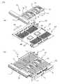
図1(a)は本出願に係る液却システムを備えるサーバモジュール1がラックキャビネット9に搭載されたラックマウントサーバ100の外観を示す斜視図である。ラックマウントサーバ100は情報処理装置の一種であり、ラックキャビネット9の中にはサーバモジュール1が単体または複数台搭載されている。サーバモジュール1を冷却するための冷却風は、前面から吸気され、サーバモジュール1の内部素子を冷却し、背面から排気される。 FIG. 1A is a perspective view showing an appearance of a
図1(b)は図1(a)に示したラックキャビネット9から1つのサーバモジュール1を引き出した状態を示す部分拡大図であり、図1(c)は1つのサーバモジュール1に搭載された空冷システムの構成を示す斜視図である。サーバモジュール1の内部には第1の発熱部品2が冷却風の流れに対してファン5の上流側にあり、ファン5の下流側にはCPU(第2の発熱部品)3や電子部品4等が配置されている。第1の発熱部品2は、例えばハードディスクやSSD(ソリッドステートディスク)等の電子部品である。ファン5による冷却風によりCPU3や電子部品4及びその他の発熱部品や電子部品が冷却される。 FIG. 1B is a partially enlarged view showing a state in which one
図2(a)は本出願の一実施例のサーバモジュール1を示すものであり、空冷システムを備えるサーバモジュール1に液冷システム10を搭載する状態を平面視した組立図である。なお、以後、液冷システム10は冷却モジュール10と記すこともある。また、図2(b)は図2(a)に示した空冷システムを備えるサーバモジュール1に液冷システム10が搭載された状態を示す平面図である。空冷システムには冷却風を発生させる複数台のファン5が備えられている。ファン5の上流側のメインボード6には図1(c)で説明した第1の発熱部品(ハードディスクやSSD等)が設けられるが、ここではその図示を省略してある。 FIG. 2A shows the
本出願ではサーバモジュール1のファン5の下流側のメインボード6の上の領域が、冷却風CAが流れる方向に沿った直線によって第1の領域A1と第2の領域A2に分けられている。第1の領域A1は、複数個の発熱部品(ここでは発熱部品3A,3B)が配置される領域であり、冷却風CAの流れる方向に沿って複数個の発熱部品3A,3Bが直列に配置されている。発熱部品3A,3Bは、例えば、CPU3A,3Bであり、発熱量が大きい強冷却必要部品である。この実施例では、CPU3BがCPU3Aの下流側に配置されている。よって、発熱部品3A,3Bは以後CPU3A,3B、或いは強冷却必要部品3A,3Bと記載することもある。第2の領域A2は第1の領域A1の両側(第1の領域A1の片側の場合もある)に位置する領域であり、冷却風で冷却可能な電子部品(弱冷却必要部品)4が配置される領域である。 In the present application, an area on the
第1の領域A1に配置されるCPU3A,3Bは、冷却風では十分な冷却ができない強冷却必要部品であるために、液冷システム10で冷却される。液冷システム10が配置される部分には、冷却風を必要としない、1W以下の発熱量を有する部品も配置される。CPU3A,3Bの配置は、液冷システム10が配置される領域内であれば、冷却風の流れ方向に直列でなくても良い。第2の領域A2に配置される電子部品4は、冷却風の供給することによって冷却可能か、又は、冷却風を供給し、且つヒートシンク等の放熱器を取り付けることで冷却可能な1W〜100W程度の発熱量を有する電子部品であり、弱冷却必要部品とも呼ばれる。このような電子部品4としては、DIMM(メモリモジュール)や電源部品等がある。 The
前述の第1の領域A1及び第2の領域A2は短冊状の矩形領域であり、細切れでない領域が確保されている。これは、液冷システム10の構成物等により、メインボード6上の領域が細かく分割された場合、空冷部品の間隔が液冷システム10により制限を受けて、システムが必要とする回路構成が実現困難となるからである。第1の領域A1のメインボード6の上の位置は、第2の領域A2の大きさや位置によって決まり、概ねメインボード6の中央部よりも少しずれた位置になる。また、第1の領域A1の両側に位置する第2の領域A2の面積は同じでなくても良い。 The first area A1 and the second area A2 described above are strip-shaped rectangular areas, and areas that are not shredded are secured. This is because when the area on the
本出願では、空冷システムの冷却風CAの下流側のメインボード6の上の領域が第1の領域A1と第2の領域A2に分けられたサーバモジュール1に、第2の領域A2への冷却風CAの流れを阻害しないような液冷システム10が、第1の領域A1に搭載される。液冷システム10は一般に、冷媒を冷却するラジエータ、発熱部品から熱を奪う(吸熱する)受熱部材、冷媒をラジエータから受熱部材に流す冷媒配管及び冷媒配管中の冷媒を移動させるポンプを備えている。受熱部材は冷却ジャケットとも呼ばれる。 In this application, the area on the
図2(a)、(b)に示す実施例では、ラジエータ11はファン5の下流側に、冷却風CAによって十分に冷却されるように設けられる。通常は冷却風CAの流れ方向に対して垂直な方向に設けられており、ファン5によって供給される冷却風CAが全て供給可能な様に配置されている。ラジエータ11の長さは複数並んだファン5の全長よりも短い。受熱部材12は各CPU3の上に設けられており、受熱部材12にラジエータ11から冷媒を供給する冷媒配管13は、第2の領域A2に入り込まないようにメインボード6の上に設けられている。ラジエータ11には複数の流路があり、冷媒配管13はマニホールド16によってラジエータ11の複数の流路に接続されている。そして、冷媒配管13と受熱部材12の間には、冷媒を一時的に貯留するタンク15と、冷媒を移動させるポンプ14が設けられている。ポンプ14は後にその構成を詳述するが、タンク15の両側に複数個設置されている。なお、ポンプ14の能力が大きければ、ポンプ14はタンク15の片側だけに設けることが可能である。 In the embodiment shown in FIGS. 2A and 2B, the
この構造では、受熱部材12の上にポンプ14とタンク15が互いに隣接するように集約されて設置されているので、これらを接続する冷媒配管13を短くでき、省スペース化が図れる。そして、冷媒配管13内を冷媒が流れる際の流路抵抗は、冷媒配管13の長さに依存する為、冷媒配管13を短くできることで、液冷システム10内を流れる冷媒の流路抵抗を小さくすることができる。また、冷媒の移動量が大きくなることにより、受熱部12からラジエータ11への熱移動が効率化される為、液冷システム10の性能を向上することができる。 In this structure, since the
更に、強冷却必要部品が、第2の領域を避けて第1の領域A1に集約されるため、液冷システム10の構成要素も第1の領域A1に集約することができる。その結果、第2の領域A2を細切れでなく、広く確保できる。そのうえ、液冷システム10が第2の領域A2に冷却風CAが流れることを阻害せず、第2の領域A2に実装される電子部品4に冷却風CAを十分に供給することができる。これらの利点により、液冷システム10の性能が向上し、300W程度の高発熱を有する発熱部品3A,3Bを冷却しつつ、冷却風CAにより冷却を行う電子部品4の冷却を阻害することなく液冷システム10をサーバに搭載可能となる。 Furthermore, since the components requiring strong cooling are concentrated in the first area A1 while avoiding the second area, the components of the
図3(a)は図2(a)に示したメインボード6に液冷システム10を搭載する状態を示す組立斜視図であり、図3(b)は図2(b)に示したサーバモジュール1の斜視図である。これらの図から分かるように、電子部品4は、実際には子ボード4Aの片面又は両面の上に実装された多くの電子部品であり、子ボード4Aは、メインボード6の上に設けられたソケット4Bに取り付けられる。また、1つのタンク15に6つのポンプ14が並列に接続されているので、冷媒の流量を増やすことができる。 3A is an assembled perspective view showing a state in which the
ここで、図9を用いて電子部品4が実装された子ボード4Aの配置並びにCPU3A,3Bとの接続の特徴について説明する。ここでは、電子部品4はメモリ(DIMM)であり、DIMM4は子ボード4Aの両面或いは片面にDRAM素子を複数個搭載した構造をとる。以後電子部品4はメモリ4、或いはDIMM4と記載することもある。子ボード4Aは冷却風CAの流れに平行に、CPU3A,3Bの両側にそれぞれ複数枚ずつ配置されている。このため、DIMM4とCPU3A,3Bの間の物理的な配線長は最短距離で済む。 Here, the arrangement of the
CPU3A,3Bの内部にはシステムコントローラ3Sとメモリアクセスコントローラ3Mがあり、メモリ4はメモリアクセスコントローラ3Mとシステムコントローラ3Sとを介してCPU3A,3Bとデータ転送を行っている。各素子間でのデータ転送には、各素子間の配線長(物理的な距離)に応じてそれぞれ時間がかかり、その間、CPUでのデータ処理は停止される。本実施例では、前述のようにメモリ4とCPU3A,3Bの間の物理的な配線長は最短距離で済むので、データ転送完了までの時間(メモリレイテンシ)が小さく、システム全体のデータ処理にかかる時間が短縮できる。 The
即ち、本実施例では、CPU3A,3Bとメモリ4の配置を最優先して、メインボード6が設計され、メインボード6上の強冷却必要部品3の配置に合わせて液冷システム10が配置されている。そのため、本実施例では、液冷システム10はメインボード6の中心からずれた場所に配置され、空冷システムは左右非対象の面積比を持っている。 That is, in this embodiment, the
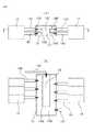
図4は、図3(a)に示した液冷システム10における冷媒配管13、ポンプ14及びタンク15の構造を示す要部拡大斜視図である。冷媒配管13は、ラジエータで冷却された低温の冷媒が流れる冷水管13Cと、発熱部品の熱を吸熱して温度が上昇した高温の冷媒が流れる温水管(図示せず)を備える。冷水管13Cはタンク15に接続されており、タンク15には6つのポンプ14が設けられている。ポンプ14はタンク15内に一時貯留された冷媒を吸入管14Sで吸い込み、吐出管14Dを通じてタンク15内に戻す。6つのポンプ14は受熱部材12からの高さを低くするために、斜めに傾いた状態でタンク15に取り付けられている。6つのポンプ14からタンク15内に戻された冷媒は合流し、冷水管13Cを通じて図示しない受熱部材に供給される。受熱部材の構造については後述する。ポンプ14の内部には図示を省略するが、ポンプ故障時に冷媒の逆流を防止している。 FIG. 4 is an essential part enlarged perspective view showing the structure of the
図5(a)は、図4に示したタンク15の内部構造の一例を示す縦断面図であり、図5(b)は図5(a)のB−B線における断面図である。これらの図から分かるように、タンク15はその内部が仕切壁15Wによって2つの部屋に分けられている。一方の部屋が貯留室15Sであり、ラジエータに接続する冷媒配管13とポンプ14の吸入管14Sが接続している。他方の部屋が混合室15Mであり、受熱部材に接続する冷媒配管13とポンプ14の吐出管14Dが接続している。貯留室15Sにはラジエータからの冷媒が流入し、一時貯留される。この時、冷媒中に含まれる空気は貯留室15Sの天井部に溜まる。ポンプ14の吸入管14Sは貯留室15Sの底面に近い部分に接続して冷媒を吸い出すので、貯留室15Sの天井部に溜まった空気がポンプ14に入ることがない。混合室15Mには各ポンプ14からの冷媒が吐出管14Dを通じて流入し、混合されて冷媒配管13から吐出される。仕切壁15Wの形状はこの実施例に限定されるものではない。 5A is a longitudinal sectional view showing an example of the internal structure of the
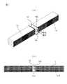
図6(a)は本出願におけるラジエータ11の一実施例の構成を示す斜視図であり、図6(b)は図6(a)に示したラジエータ11の正面図である。この実施例のラジエータ11は、マニホールド16を中心にして、左側に4つの放熱流路を備え、右側に4つの放熱流路を備えている。各流路は偏平状の流路がU字状に折り返された形状をしており、対向する流路の間には放熱効率を上げるための波形のフィン11Fが設けられている。 6A is a perspective view showing a configuration of an embodiment of the
各流路はマニホールド16に接続されている。マニホールド16には冷媒入口部16Hと冷媒出口部16Cとがある。冷媒入口部16Hはマニホールド16の内部で、マニホールド16の左側にある4つの放熱流路の一方の端部に接続しており、冷媒出口部16Cはマニホールド16の内部で、マニホールド16の右側にある4つの放熱流路の一方の端部に接続している。左側と右側の放熱流路の冷媒入口部16Hと冷媒出口部16Cに接続しない他方の端部同士は、マニホールド16の内部で連通している。 Each flow path is connected to the
冷媒入口部16Hに図示しない冷媒配管から流入した冷媒(温水)は、マニホールド16の左側にある4つの放熱流路に流入し、端部でUターンしてマニホールド16に戻り、続いてマニホールド16の右側にある4つの放熱流路に流入する。マニホールド16の右側にある4つの放熱流路に流入した冷媒は、端部でUターンして再びマニホールド16に戻り、冷媒出口部16Cから排出されて図示しない冷媒配管に流入する。冷媒入口部16Hから流入する冷媒は温水であるが、冷媒出口部16Cから排出される冷媒は、ラジエータ11の放熱流路で冷却されるので冷水である。 Refrigerant (warm water) that has flowed into the
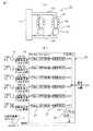
図7(a)は、図2(a)及び図3(a)に示した液冷システム10における冷媒の流れを説明する説明図であり、図7(b)は図7(a)に示した液冷システム10におけるポンプの制御回路の構成の一実施例を示す回路図である。前述のように、冷媒はラジエータ11で冷却され、冷水管13Hでタンク15に流入した後にポンプ14によって受熱部材12に送られて発熱部品を冷却し、温度が上昇した冷媒は温水管13Hでラジエータ11に戻る。 Fig.7 (a) is explanatory drawing explaining the flow of the refrigerant | coolant in the
各ポンプ14には図示は省略するが回転数検出センサが取り付けられており、各ポンプ14の動作はその回転数信号(パルス信号)が入力される制御回路(サービスプロセッサ)20によって監視されている。制御回路20には、パルス信号を回転数信号に変換する変換回路21、各ポンプ14の回転数を閾値と比較する閾値判定回路22、閾値判定回路22からの出力によりポンプ14が正常か否かを判定する部品判定回路23及びシステム判定回路24がある。 Although not shown, each pump 14 is provided with a rotation speed detection sensor, and the operation of each
例えば、6台のポンプ14のうち、1台のポンプ14が故障した場合は、1台のポンプ14からの回転数信号が制御回路20に入力されないが、制御回路20は1台程度の故障では液冷システム10による発熱部品の冷却には支障がないと判定する。そして、部品判定回路23からはポンプ14の1台が故障した通知が出力されるが、システム判定回路24からは液冷システムの動作続行(OK)が出力され、液冷システム10による発熱部品3の冷却が続行される。このようにポンプ14の制御に冗長性を持たせたことにより、ポンプ14が故障した場合でも、冷却能力が確保できる場合は液冷システム10が止まらず、CPUの冷却を続行することができるので、信頼性が確保できる。 For example, when one
図8は、図7(b)に示したポンプ14の制御回路20の制御手順の一実施例を示すフローチャートである。ステップ801で液冷システムの動作が開始されると、制御回路20はステップ802で各ポンプの回転数xの読み込みを行う。サーバモジュールが動作している間、ポンプの回転数は常に制御回路によって監視されている。そして、ステップ803において各ポンプの回転数xが閾値(2050rpm)以上か否かを判定する。全てのポンプの回転数xが閾値以上であれば(YES)ステップ802に戻り、各ポンプの回転数xの読み込みを続行する。 FIG. 8 is a flowchart showing an embodiment of a control procedure of the
一方、ステップ803の判定で、ポンプの回転数xに閾値を越えないものがあった場合(NO)はステップ804に進み、ポンプの故障を通知してステップ805に進む。ステップ805ではポンプの故障が1台か否かを判定し、ポンプの故障が1台であれば(YES)、前述のように液冷システムによる発熱部品の冷却には支障がないと判定してステップ802に戻り、各ポンプの回転数xの読み込みを続行する。ところが、ステップ805でポンプの故障が複数台と判定した場合(NO)は、液冷システムによる発熱部品の冷却には支障があると判定してステップ806に進み、冷却システムの動作を停止させてこのルーチンを終了する。 On the other hand, if it is determined in
図10は、本出願に係る液冷システム10におけるポンプ14とタンク15の下部にある部材の構成を詳細に示す分解斜視図である。ポンプ14とタンク15の下部には、ポンプ支持機構50と受熱部材12とがあり、受熱部材12は受熱部材固定部品17で図示しないメインボード上に固定される。受熱部材固定部品17の内部には雌ネジが形成されており、図12に示される雄ネジ19と螺合する。ポンプ支持機構50は、ポンプ置部51、ベース板52、取付部54及びブラケット(ポンプ取付金具)55を備える。また、受熱部材12は板金40、CPU用板金60、及びコールドプレート90を備える。 FIG. 10 is an exploded perspective view showing in detail the configuration of members under the
板金40には、段差部41、CPU電源部用板金部42、CPU用板金部43、搭載部品との干渉を避けるための孔44、凹部45及び受熱部材固定部品17を挿通する孔46がある。CPU用板金60には、ベース板61と受熱部材固定部品17を挿通する取付孔62がある。コールドプレート90には、冷水入口91、冷媒流路92、CPU用コールドプレート93、Uターン流路94及びCPU電源用コールドプレート95がある。板金40、CPU用板金60及びコールドプレート90を構成する各部材については拡大した図面を使用して後に詳述する。 The
ここで、本出願のサーバモジュールに設ける防風壁と漏水トレイについて説明する。図11(a)は空冷システムを備えるサーバモジュール1内を流れる冷却風CAの流れと、サーバモジュール1内の中央部に防風壁7を設置した場合の冷却風CAの流れを比較する比較図である。サーバモジュール1内に防風壁7がない場合は、ファンで生成された冷却風CAは、電子部品4が密集する部分には流路抵抗があるので、背の低い発熱部品3(CPU3A,3B)が実装されたメインボード6の上を主に流れる。 Here, the windbreak wall and the water leakage tray provided in the server module of the present application will be described. FIG. 11A is a comparison diagram comparing the flow of the cooling air CA flowing through the
流路抵抗は、高密度実装でメインボード6の上の部品間の間隔が狭いのと、その領域に搭載される部品の背が高いために発生する。即ち、電子部品4にはDIMM、電源モジュール等のメインボード6に垂直に立った子ボード4Aの上に回路が形成された構造をとっているため背が高く、そのために冷却風CAの流路をDIMM、電源モジュール等が遮ってしまうので、流路抵抗が発生するのである。これに対して、CPU3A,3Bは、メインボード6の上に直接実装されるので、DIMM、電源モジュール等と比べて背が低くなっている。DIMMのボード6からの高さは例えば33mmである。また、漏水トレイ8のボード6からの高さは例えば26.5mmである。漏水しないための漏水トレイ8の高さの下限値は約半分の13mmであり、筐体の天板に接触しないための漏水トレイ8の高さの上限値は35mmである。この高さの範囲であれば漏水せずにDIMM及び電源の冷却の高効率化が期待される。 The flow path resistance is generated due to a high density mounting and a narrow interval between components on the
背の低い発熱部品3が実装されたメインボード6の上に、前述のような液冷システム10を破線で示すように設けた場合でも、冷却風CAは液冷システムの周囲に流れるので、冷却風CAによる電子部品4の冷却能力が低下する。即ち、上記破線内の領域には液冷対象の強冷却必要部品と空冷を必要としない程度の低発熱(無発熱含む)の弱冷却必要部品のみが実装されており、冷却風の供給を必要としないにも関わらず、冷却風が流れ込む。その為、相対的に冷却風の供給が必要な電子部品4に供給する冷却風が減少する為、電子部品4の冷却性能が低下するのである。 Even when the
そこで、発熱部品3の周囲に冷却風CAが流れ込まないように、発熱部品3の上に搭載された液冷システム10の周囲を防風壁7で覆い、強冷却必要部品3に冷却風CAが流れ込まないようにする。この結果、冷却風の供給を必要としない領域への冷却風の流入を防止することができ、冷却風が必要な弱冷却必要部品4に冷却風の全てを供給することができる為、冷却風CAによる電子部品4の冷却能力が向上する。 Therefore, in order to prevent the cooling air CA from flowing around the
更に、図11(b)に示すように、メインボード6の上に搭載された発熱部品3と液冷システム10の周囲に設けた防風壁7の上部に天井壁70を形成し、発熱部品3と液冷システム10の全体を壁で覆えば冷却風CAによる電子部品4の冷却能力が一層向上する。また、発熱部品3と液冷システム10の周囲に防風壁7を設ける場合、図11(c)に示すように、防風壁7の上流側に湾曲部を設けたり、図11(d)に示すように、防風壁7の上流側にテーパー部を設ければ、冷却風CAが電子部品側に流れ易くなる。 Further, as shown in FIG. 11 (b), a
ところで、これまでに説明した液冷システム10では、冷却を行う冷媒が液体(例えば水)であるので、冷媒配管13や冷媒配管13と受熱部材12、ポンプ14或いはタンク15との接続部から冷媒が漏れる可能性がある。そして、液冷システム10から冷媒が漏れると、漏れた冷媒がメインボード6の上に溢れて電子部品4が浸水して回路が短絡する虞がある。そこで、液冷システム10の受熱部材、ポンプ14及びタンク15の下方に、漏れた冷媒の他の場所への流出を防止する漏水トレイを設置することが考えられる。 By the way, in the
図12は、図3(a)に示したメインボード6と、メインボード6の上に取り付けられる液冷システム10の間に漏水トレイ8を挿入した状態を示す組立斜視図であり、図13(a)がメインボード6の上に漏水トレイ8と液冷システム10とを取り付けた状態を示す斜視図である。メインボード6の上にはCPU3A,3B、子ボードを取り付けるソケット4B及びCPU用の電源回路30A,30Bが実装されているものとする。また、液冷システム10には、前述のように、ラジエータ11、受熱部材12、冷媒配管13、ポンプ14、タンク15及びマニホールド16がある。 12 is an assembly perspective view showing a state in which the
漏水トレイ8は、ベース板80、CPU接触用孔8A,8B、電源回路接触用孔8HA,8HB、及びベース板80の周囲に突設された防風壁7を備える。CPU接触用孔8A,8Bは、メインボード6の上にあるCPU3A,3Bを挿通させるための孔であり、電源回路接触用孔8HA,8HBは、CPU用の電源回路30A、30Bを挿通させるための孔である。また、CPU接触用孔8A,8Bの間のベース板80にはスリーブ8Sが設けられている。スリーブ8Sについては後述する。 The
防風壁7は漏水トレイ8のベース板80の外縁部を延長して上方に折り曲げることにより形成される。これは、漏水トレイ8のベース板80外縁部には、液冷システム10からの漏水を漏水トレイ8内に留めるための折り曲げ部が必要であるので、この折り曲げ部を上方に延長して壁の高さを大きくし、防風壁7を兼ねさせたものである。メインボード6の上に漏水トレイ8を取り付け、その上に液冷システム10を取り付けると、図13(a)に示すように、ポンプ14とタンク15の周囲には防風壁7が突出し、冷却風がポンプ14とタンク15がある領域に入って来なくなる。 The
図13(b)は図13(a)に示した液冷システム10の、冷却風の流れに垂直な方向の断面図である。受熱部材固定部品17はバネ17Bが上部に巻きつけられたネジ部品であり、板金40側から板金40、CPU用板金60、漏水トレイ8及びメインボード6を挿通して、メインボード6の裏面側に取り付けられた固定板18に螺着される。バネ17Bは、受熱部材固定部品17の頭部17Hと板金40との間に挿入され、板金40をメインボード6側に付勢している。この図から、防風壁7の内側には冷水管13C,温水管13H,からコールドプレートの冷媒流路92までの範囲の部品が全て収納され、冷却風が液冷システム10内に入って来ないことが分かる。 FIG. 13B is a cross-sectional view of the
一方、図14(a)は、図13(a)に示した液冷システム10の、冷却風の流れに沿った方向の部分断面図である。図14(a)にはCPU3Aの部分のみが示してあり、CPU3B側の断面は省略してある。この図からも受熱部材固定部品17が雄ネジ19及びメインボード6の裏面側にある固定板18に螺着され、バネ17Bが頭部17H側から板金40をメインボード6側に付勢していることが分かる。 On the other hand, FIG. 14A is a partial cross-sectional view of the
ここで、図10に示した板金40、CPU用板金60及びコールドプレート90と、図12に示したメインボード6と漏水トレイ8との係合状態を図14(a)を用いて説明する。メインボード6には、CPU用電源回路30Aとして第1の部品30A1と第2の部品30A2と、CPU3Aが実装されている。メインボード6に漏水トレイ8が取り付けられた状態では、CPU用電源回路30Aは、漏水トレイ8の電源接触用孔8HAの中に入り、CPU3Aは漏水トレイ8のCPU接触用孔8Aの中に入る。漏水トレイ8のベース80のメインボード6側の面において、CPU接触用孔8A,8Bをパッキンで囲んでもよい。パッキンがCPU3A、3Bの周囲に密着し、止水の効果が高められる。 Here, the engaged state of the
図10に示したコールドプレート90には、CPU用コールドプレート93と、CPU電源用コールドプレート95とがある。CPU用コールドプレート93には2つの流路があり、一方の流路の一端は冷水入口91に接続し、他端はUターン流路94に接続している。他方の流路は、その一端がUターン流路94に接続し、他端が冷媒流路92に接続している。冷媒流路92は内部で流路が二分されており、冷水入口91がある冷媒流路92とUターン流路94を経た冷媒が戻ってくる冷媒流路92とは連通していない。従って、Uターン流路94を経て冷媒流路92に戻ってきた冷媒は、全量がCPU電源用コールドプレート95に流入して冷媒配管13の温水管13Hに流入する。冷媒の流れは図10に矢印で示される。The
液冷システム10が漏水トレイ8の上に取り付けられると、受熱部材12を形成するコールドプレート90のCPU用コールドプレート93がCPU3Aの直上に位置し、CPU電源用コールドプレート95がCPU用電源回路30Aの直上に位置する。このとき、CPU3Aは熱伝導シート31を介してCPU用コールドプレート93に重なるが、CPU用電源回路30Aの第1の部品30A1は背が低いのでCPU電源用コールドプレート95に重ならない。そこで、CPU用電源回路30Aの第1の部品30A1の上には、CPU電源用コールドプレート95に接触させるための金属棒32が熱伝導シート31を介して設けられている。When the
CPU板金60は、ベース板61の四隅に取付孔62を備えるものであり、取付孔62を挿通する受熱部材固定部品17によってベース板61がCPU用コールドプレート93に重なるように設けられている。
板金40はCPU用板金部43を備えており、このCPU用板金部43にはベース板61の四隅にある取付孔62に重なる孔46が設けられている。板金40の一方の端部には段差部41があり、この段差部41はバネ性を備えている。そして段差部41に続くCPU電源用板金部42はCPU用板金部43より一段低くなっており、取付時にメインボード6に近づくように形成されている。板金40は、受熱部材固定部品17によって取り付けられた状態では、CPU用板金部43がCPU板金60のベース板61に重なり、CPU電源用板金部42がCPU電源用コールドプレート95に重なる。また、板金40のCPU用板金部43がCPU板金60のベース板61に重なった状態では、CPU電源用板金部42の下面のメインボード6からの高さは、CPU電源用コールドプレート95の上面のメインボード6からの高さよりも低くなっている。このため、板金40が受熱部材固定部品17によって取り付けられ、CPU電源用板金部42がCPU電源用コールドプレート95に重なった状態では、段差部41のバネ性により、CPU電源用コールドプレート95がCPU電源用板金部42によって付勢される。 The
以上のような構成により、メインボード6の第1の領域A1の中に配置されたCPU3A,3B及びCPU用電源部品30Aにある部品が発生する熱は、CPU用コールドプレート93とCPU電源用コールドプレート95によって吸熱される。 With the above configuration, the heat generated by the components in the
なお、液冷システム10からの漏水を防止するための漏水トレイ8は、図14(b)や図14(c)に示すように、底板を二重構造にすると、液冷システム10から漏れた冷媒を逃がし難い。図14(b)は二重底84にドレイン83を設けた実施例を示しており、図13(c)は2枚の傾斜底85、86を設けた実施例の構成を示すものである。また、漏水トレイ8を二重底にせずに、図13(d)に示す別の実施例のように、漏水トレイ8の底板に吸水シート87を挿入して、液冷システム10から漏れた冷媒を逃がし難くすることが可能である。 It should be noted that the
図15(a)は、液冷システム10のタンク15の両側に配置する6つのポンプ14の取付状態を示す部分拡大斜視図である。前述のように、タンク15には6つのポンプ14が接続されており、タンク15には冷媒配管13の冷水管13Cから冷媒が供給されている。ポンプ14とタンク15の間は吸入管14Sと吐出管14Dで接続されており、タンク15の中の冷媒はポンプ14によって吸い出され、加圧されてタンク15に戻される。ポンプ14によって加圧された冷媒は、供給側とは反対側のタンク15の端部から冷水管13Cを通じて受熱部材12に供給される。受熱部材12の構造は既に説明したので、同じ構成部材には同じ符号を付してその説明を省略する。吸熱した冷媒は、受熱部材12のCPU電源用コールドプレート95から温水管13Hに戻される。 FIG. 15A is a partially enlarged perspective view showing the attachment state of the six
図15(b)は図15(a)に示した構造から6つのポンプ14を除去してポンプ支持機構50の構造を説明する部分拡大斜視図である。タンク15は、冷媒配管13側に設けられた取付脚15Aがねじ53でポンプ支持機構50のベース板52に固定されている。また、ベース板52には3つのポンプ置部51を備えたブラケット55の両端部にある取付部54がねじ53で固定されている。ポンプ14をタンク15に対して斜めに配置するために、ポンプ置部51は直角溝となっている。タンク15の側面にはポンプ14に冷媒を送り出す吐出口15Tとポンプから冷媒が流入する吸入口15Kとがある。ブラケット50は、例えばSUS(ステンレス鋼板)で構成されている。そして、ポンプ置部51にはブラケット55とポンプ14の間に挟む緩衝板が取り付けられる。この緩衝板により、受熱部材12とタンク15の変形、製造時の寸法公差によりズレが生じても、このズレを吸収することができる。 FIG. 15B is a partially enlarged perspective view for explaining the structure of the
図16は、空冷システムと本出願の液冷システム10が搭載されたサーバモジュール1の第2の実施例を示す平面図である。第2の実施例のサーバモジュール1が前述の実施例と異なる点は、サーバモジュール1の背面側に、上下方向に積み重ねられたサーバモジュール1にあるメインボード6同士を接続する接続ユニット(以後XBユニットと言う)71が設けられている点である。XBユニット71は、液冷システム10を備える第1の領域A1の一方の側にある第2の領域A2の、冷却風の流れの下流側に設けられている。第1の領域A1にある液冷システム10の構成並びに第1の領域A1の両側に配置された第2の領域A2の構成は、既に説明した実施例と同様であるので、同じ構成部材には同じ符号を付してその説明を省略する。 FIG. 16 is a plan view showing a second embodiment of the
サーバモジュール1の第2の実施例のように、サーバモジュール1にXBユニット71が設けられている場合、XBユニット71の内部には図17に示すように、動作時に発熱が大きくなるXBチップ73が存在している。そして、このXBチップ73は冷却風によって冷却する必要がある弱冷却必要部品である。このため、サーバモジュール1の第2の実施例では、サーバモジュール1の筐体に対して、第1の領域A1と2つの第2の領域A2は、筐体に対して一方の側にシフトされており、シフトによって空いた部分を通じて冷却風CAをXBユニット71に送っている。 When the
図18は図16、図17で説明した第2の実施例のサーバモジュール1内に、液冷システム10が設けメインボード6を2枚重ねて取り付ける本出願のサーバモジュール1の第3の実施例を示す組立斜視図である。ここで、第1と第2の領域A1、A2を備え、それぞれの領域に既に説明した発熱部品や電子部品が実装され、液冷システム10を備えたメインボード6をシステムユニットと呼ぶことにする。すると、第3の実施例のサーバモジュール1には、第1のシステムユニットU1がまず筐体上に取り付けられ、第1のシステムユニットU1の上側に、第2のシステムユニットU2が重ねて取り付けられる。第1のシステムユニットU1のメインボード6にある電子部品の位置と、第2のシステムユニットU2のメインボード6にある電子部品の位置は全く同じである。 FIG. 18 shows a third embodiment of the
この場合、第2のシステムユニットU2のメインボード6の底面には、図19に示すような接続コネクタ70が取り付けられる。接続コネクタ70は、第1のシステムユニットU1の上側に第2のシステムユニットU2が重ねて取り付けられた時に、第2のシステムユニットU2にある回路を第1のシステムユニットU1にある回路に接続するためのものである。第1のシステムユニットU1と第2のシステムユニットU2とが接続コネクタ70を通じて電気的に接続されると、一方のメインボード6にあるCPU3A,3Bが他方のメインボード6にあるDIMM4のデータを使用することができる。 In this case, a
第2のシステムユニットU2の底面に設けられた接続コネクタ70の位置は、第1のシステムユニットU1のメインボード6に取り付けられた漏水トレイ8にあるスリーブ8Sの位置と同じである。この場合、第1のシステムユニットU1のメインボード6には、漏水トレイ8のスリーブ8S内に、第2のシステムユニットU2のメインボード6の底面に設けられた接続コネクタ70に嵌合するコネクタ(ペアコネクタ)が実装される。従って、第1のシステムユニットU1の上側に第2のシステムユニットU2が重ねて取り付けられると、第2のシステムユニットU2にある接続コネクタ70が第1のシステムユニットU1にあるスリーブ8Sに挿入され、ペアコネクタに接続される。 The position of the
図20は、図18に示した第1と第2のシステムユニットU1,U2が重ね合された状態を示すサーバモジュール1の要部の斜視図であり、ファンの図示は省略してある。この図から分かるように、第1のシステムユニットU1の上側に第2のシステムユニットU2が重ねて取り付けられた状態でも、XBユニット71への冷却風の通路は確保されている。なお、図18に示すように、ファン5の大きさは、2段に重ねられたラジエータ11に十分な冷却風を送ることができる大きさである。 FIG. 20 is a perspective view of a main part of the
このように本出願によれば、高い発熱量を放熱する能力を持ち、且つ省スペースで所定の装置に高密度実装でき、更には冷却対象以外の部品の搭載可能エリアを広く確保できる液冷システムを提供できる。また、冷媒を輸送するポンプが冗長構成かつ冗長制御を持つことで、高信頼度を確保し、且つ冷却対象以外の部品の冷却を阻害しない液冷システム及びそれを実装した電子機器を提供することが可能である。 As described above, according to the present application, the liquid cooling system has the ability to dissipate a high calorific value, can be mounted on a predetermined device in high density in a small space, and can secure a wide mounting area for parts other than the cooling target. Can provide. Also, a liquid cooling system that secures high reliability and does not hinder cooling of components other than the cooling target by providing a redundant configuration and redundant control for the pump for transporting the refrigerant, and an electronic device mounted with the liquid cooling system are provided. Is possible.
本出願の液冷システムにより、ラジエターサイズが高さ36mm、奥行59mm、幅350mmの時に、ポンプ流量0.9l/分で、2個の300WのCPUの冷却が可能である。また、DIMMを冷却する冷却風の経路にはラジエータしか存在しないため、効率的に冷却風がDIMMに当たり、256WのDIMM(8WのDIMMが32枚)の冷却が可能となる。また、ポンプ異常通知があることにより、異常発生から交換が短時間で行われることを前提とした場合、ポンプが2台同時に故障する可能性がなくなり、液冷システムのシステム故障が発生する可能性を無くすことが出来る。 With the liquid cooling system of the present application, two 300 W CPUs can be cooled at a pump flow rate of 0.9 l / min when the radiator size is 36 mm high, 59 mm deep, and 350 mm wide. Further, since only the radiator exists in the cooling air path for cooling the DIMM, the cooling air efficiently hits the DIMM, and 256 W DIMMs (32 8 W DIMMs) can be cooled. In addition, if there is a notification of pump abnormality, it is no longer possible that two pumps will fail at the same time if replacement is performed in a short time after the occurrence of the abnormality, and a liquid cooling system failure may occur. Can be eliminated.
以上、本出願を特にその好ましい実施の形態を参照して詳細に説明した。本出願の容易な理解のために、本出願の具体的な形態を以下に付記する。 The present application has been described in detail with particular reference to preferred embodiments thereof. For easy understanding of the present application, specific forms of the present application are appended below.
(付記1) ファンと、
前記ファンが発生する冷却風の下流に位置し、該冷却風に平行な実装面を有する回路基板と、
前記冷却風の方向に沿った直線で前記実装面上に区画され、それぞれ複数の電子部品を搭載する第1及び第2の領域と、
前記電子部品として前記第1の領域に搭載され、液体冷媒により冷却される複数の発熱部品と、を備えることを特徴とする電子機器。
(付記2) 前記第2の領域が前記第1の領域の両側に配置されることを特徴とする付記1に記載の電子機器。
(付記3) 前記発熱部品として複数のCPUが搭載され、前記第2の領域に複数のメモリが搭載されることを特徴とする付記1又は2に記載の電子機器。
(付記4) 前記メモリはマトリクス状に配列されたことを特徴とする付記3に記載の電子機器。
(付記5) 前記発熱部品として、第1の発熱部品及び前記発熱部品と高さが異なる第2の発熱部品が前記第1の領域に搭載されることを特徴とする付記1または2に記載の電子機器。(Appendix 1) With fans
A circuit board located downstream of the cooling air generated by the fan and having a mounting surface parallel to the cooling air;
First and second regions that are partitioned on the mounting surface in a straight line along the direction of the cooling air and each mount a plurality of electronic components;
An electronic device comprising: a plurality of heat generating components mounted in the first region as the electronic components and cooled by a liquid refrigerant.
(Additional remark 2) The said 2nd area | region is arrange | positioned at the both sides of the said 1st area | region, The electronic device of
(Supplementary note 3) The electronic device according to
(Supplementary note 4) The electronic device according to
(Supplementary note 5) The
(付記6) 前記ファンの下流側に配置され、前記冷媒の流入部と流出部とを有し、前記冷却風によって前記冷媒を冷却するラジエータと、
前記流出部と前記流入部との間で、前記第2の領域上を避ける経路に沿って前記冷媒を流通する冷媒配管と、
前記冷媒配管の途中に設けられ、前記冷媒と前記発熱部品との間で熱交換を行う受熱部材と、
前記冷媒配管の途中に設けられ、前記冷媒を移動させるポンプと、
を有することを特徴とする付記1から付記5に記載の電子機器。
(付記7) 分岐された後の前記冷媒配管と前記受熱部材との間に、前記冷媒を一時貯留するタンクが設けられており、
前記ポンプは前記タンクの各個に複数取り付けられていることを特徴とする付記6に記載の電子機器。
(付記8) 前記ラジエータは、前記冷却風に対して前記ファンの下流側で且つ前記発熱部品の上流側に配置されていることを特徴とする付記6又は7に記載の電子機器。
(付記9) 前記基板と前記冷媒配管との間の隙間に挿入されるベース板、及び前記ベース板の周囲から前記回路基板の垂直方向に起立し、前記冷媒配管及び前記前記タンクを包囲する壁部とを有する漏水トレイを備えることを特徴とする付記1から8の何れかに記載の電子機器。
(付記10) 前記ベース部には複数の開口が設けられ、前記開口内に前記発熱部品が挿通することを特徴とする付記9に記載の電子機器。(Additional remark 6) The radiator which is arrange | positioned in the downstream of the said fan, has an inflow part and an outflow part of the said refrigerant | coolant, and cools the said refrigerant | coolant with the said cooling air,
A refrigerant pipe that circulates the refrigerant along a path that avoids the second region between the outflow part and the inflow part;
A heat receiving member that is provided in the middle of the refrigerant pipe and performs heat exchange between the refrigerant and the heat generating component;
A pump that is provided in the middle of the refrigerant pipe and moves the refrigerant;
The electronic device according to
(Appendix 7) A tank for temporarily storing the refrigerant is provided between the refrigerant pipe after being branched and the heat receiving member,
The electronic device according to
(Additional remark 8) The said radiator is arrange | positioned with respect to the said cooling air in the downstream of the said fan, and the upstream of the said heat-emitting component, The electronic device of
(Supplementary Note 9) A base plate inserted in a gap between the substrate and the refrigerant pipe, and a wall that stands up in the vertical direction of the circuit board from the periphery of the base plate and surrounds the refrigerant pipe and the tank The electronic device according to any one of
(Additional remark 10) The said base part is provided with several opening, The said heat-emitting component is penetrated in the said opening, The electronic device of
(付記11) 前記ポンプはポンプ取付金具に保持された状態で前記タンクの側面に取り付けられていることを特徴とする付記7に記載の電子機器。
(付記12) 前記ポンプはポンプ取付金具との間に緩衝板が取り付けられることを特徴とする付記11に記載の電子機器。
(付記13) 前記受熱部材は、前記第1の領域にある第1の発熱部品用のコールドプレートと第2の発熱部品用のコールドプレートとを備えることを特徴とする付記6から12の何れかに記載の電子機器。
(付記14) 前記受熱部材は板金を備えており、該板金は前記第1の発熱部品用のコールドプレートに接触する第1の板金部と、前記第2の発熱部品用のコールドプレートに接触する第2の板金部とを備えることを特徴とする付記13に記載の電子機器。
(付記15)複数の前記回路基板が前記実装面に垂直な方向に積層されて互いに電気的に接続されることを特徴とする付記1〜14のいずれかに記載の電子機器。(Additional remark 11) The said pump is attached to the side surface of the said tank in the state hold | maintained at the pump mounting bracket, The electronic device of
(Supplementary note 12) The electronic device according to
(Supplementary note 13) Any one of
(Additional remark 14) The said heat receiving member is equipped with the sheet metal, and this sheet metal contacts the 1st sheet metal part which contacts the cold plate for said 1st heat generating components, and the cold plate for said 2nd heat generating components. The electronic apparatus according to
(Supplementary note 15) The electronic device according to any one of
(付記16) 前記電子機器の一方の側面に近い背面部に、上下方向に重ねられた別の電子機器と接続する接続機構が設けられており、前記回路基板は、前記接続機構内にある冷却必要部品に冷却風を送る送風路を確保するために、他方の側面側にオフセットされて前記電子機器の筺体内に配置されていることを特徴とする付記1から15の何れかに記載の電子機器。
(付記17) 前記複数の回路基板を互いに電気的に接続するコネクタが前記複数の強冷却部品間の空間に配置されることを特徴とする付記15または16に記載の電子機器。
(付記18) 前記冷媒の流入部と流出部とを有し、冷却風によって前記冷媒を冷却するラジエータと、
前記流出部から前記冷却風の方向に沿った直線上を延伸する冷水管と、
前記冷却風の方向に対して垂直な方向に前記冷水管に隣接し、前記冷却風の方向に沿って配列され、前記冷水管に互いに並列に接続されて発熱部品と前記冷媒との間で熱交換を行う複数の受熱部と、
前記受熱部に接続され、前記冷却風の方向に沿って延伸し、前記受熱部を通過した前記冷媒を前記流入部へ流す温水管と、を備えることを特徴とする冷却モジュール。
(付記19) 前記冷水管と前記複数の受熱部との間の前記冷媒経路上に、前記冷媒を貯留する複数のタンクが設けられ、前記タンクは前記受熱部上に配置されることを特徴とする付記18に記載の冷却モジュール。
(付記20) 前記複数のタンクそれぞれに、前記冷媒を移動させる複数のポンプが取り付けられていることを特徴とする付記19に記載の冷却モジュール。(Supplementary Note 16) A connection mechanism for connecting to another electronic device stacked in the vertical direction is provided on a back surface portion near one side surface of the electronic device, and the circuit board is cooled in the connection mechanism. The electronic device according to any one of
(Supplementary note 17) The electronic device according to
(Supplementary Note 18) A radiator having an inflow portion and an outflow portion for the refrigerant, and cooling the refrigerant with cooling air;
A cold water pipe extending on a straight line along the direction of the cooling air from the outflow part;
Adjacent to the cold water pipe in a direction perpendicular to the direction of the cooling air, arranged along the direction of the cooling air, and connected to the cold water pipe in parallel to each other, heat is generated between the heat generating component and the refrigerant. A plurality of heat receiving parts to be exchanged;
A cooling module comprising: a hot water pipe connected to the heat receiving portion, extending along the direction of the cooling air, and flowing the refrigerant that has passed through the heat receiving portion to the inflow portion.
(Supplementary note 19) A plurality of tanks for storing the refrigerant are provided on the refrigerant path between the cold water pipe and the plurality of heat receiving units, and the tanks are disposed on the heat receiving units. The cooling module according to
(Supplementary note 20) The cooling module according to
1 サーバモジュール(電子機器)
3 発熱部品(CPU、強冷却必要部品)
4 電子部品(メモリ、DIMM)
6 メインボード
7 防風壁
8 漏水トレイ
10 液冷システム(冷却モジュール)
11 ラジエータ
12 受熱部材(冷却ジャケット)
13 冷媒配管
14 ポンプ
15 タンク
16 マニホールド
30 CPU用電源部品
40 板金
50 ポンプ支持機構
55 ポンプ取付金具(ブラケット)
60 CPU用板金
70 接続コネクタ
71 接続ユニット(XBユニット)
90 コールドプレート
93 CPU用コールドプレート
95 CPU電源用コールドプレート1 Server module (electronic equipment)
3 Heat-generating parts (CPU, parts that require strong cooling)
4 Electronic components (memory, DIMM)
6
11
13 Refrigerant piping 14
60 Sheet metal for
90
Claims (9)
Translated fromJapanese前記ファンが発生する冷却風の下流に位置し、該冷却風に平行な実装面を有する回路基板と、
前記回路基板上に搭載され、前記冷却風の方向に沿って配置される複数のプロセッサと、
前記回路基板上に搭載され、前記複数のプロセッサそれぞれの両側に配置され、前記冷却風により冷却される複数のメモリと、
前記回路基板上に搭載され、前記ファンの下流側に配置され、前記冷却風によって液体冷媒を冷却するラジエータと、
前記回路基板上に搭載され、前記ラジエータで冷却された液体冷媒と前記複数のプロセッサそれぞれとの間で熱交換を行う複数の受熱部材と、
前記回路基板上に搭載され、前記ラジエータと前記複数の受熱部材との間に前記液体冷媒を流通させる冷媒配管と、を備え、
前記回路基板は、前記冷却風の方向に沿った領域のうち、前記複数のプロセッサを搭載する第1領域と、前記複数のメモリを搭載し該第1領域の両側にある第2領域と、を有し、
前記冷媒配管は、前記第1領域上に前記冷却風の方向に沿って配置され、前記複数の受熱部材に並列に分岐し、
前記複数の受熱部材は、前記第1領域に配置される、
ことを特徴とする電子機器。With fans,
A circuit board located downstream of the cooling air generated by the fan and having a mounting surface parallel to the cooling air;
A plurality of processors mounted on the circuit board and disposed along the direction of the cooling air;
A plurality of memories mounted on the circuit board, disposed on both sides of each of the plurality of processors, and cooled by the cooling air;
A radiator mounted on the circuit board, disposed on the downstream side of the fan, and for cooling the liquid refrigerant by the cooling air;
A plurality of heat receiving members mounted on the circuit board and performing heat exchange between each of the plurality of processors and the liquid refrigerant cooled by the radiator;
A refrigerant pipe mounted on the circuit board and allowing the liquid refrigerant to flow between the radiator and the plurality of heat receiving members;
The circuit board includes: a first area in which the plurality of processors are mounted in areas along the direction of the cooling air; and a second area in which the plurality of memories are mounted and on both sides of the first area. Have
The refrigerant pipe is disposed on the first region along the direction of the cooling air, and branches in parallel to the plurality of heat receiving members,
The plurality of heat receiving members are disposed in the first region.
An electronic device characterized by that.
前記回路基板上に搭載された前記冷媒配管は、前記ラジエータで冷却された液体媒体が前記流出部から前記複数の受熱部材に流れる1つの第1冷媒配管と、前記複数の受熱部材で熱交換された液体媒体が前記複数の受熱部材から前記流入部に流れる1つの第2冷媒配管でありThe refrigerant pipes mounted on the circuit board are heat-exchanged by the plurality of heat receiving members with one first refrigerant pipe through which the liquid medium cooled by the radiator flows from the outflow portion to the plurality of heat receiving members. A second refrigerant pipe through which the liquid medium flows from the plurality of heat receiving members to the inflow portion.
前記第1冷媒配管は、前記第1領域上に前記冷却風の方向に沿って配置され、前記複数の受熱部材に並列に分岐し、The first refrigerant pipe is disposed on the first region along the direction of the cooling air, and branches in parallel to the plurality of heat receiving members,
前記第2冷媒配管は、前記第1領域上に前記冷却風の方向に沿って配置され、前記複数の受熱部材に並列に分岐する、ことを特徴とする請求項1記載の電子機器。2. The electronic device according to claim 1, wherein the second refrigerant pipe is disposed along the direction of the cooling air on the first region and branches in parallel to the plurality of heat receiving members.
前記冷媒配管は上下2段に分かれ、片方の冷媒配管に前記ラジエータで冷却された液体媒体が流れ、もう片方の冷媒配管に前記複数の受熱部材で熱交換された液体媒体が流れる、ことを特徴とする請求項1記載の電子機器。The radiator has an inflow portion into which the liquid refrigerant flows and an outflow portion from which the liquid refrigerant flows out,
The refrigerant pipe is divided into upper and lower stages, a liquid medium cooled by the radiator flows through one refrigerant pipe, and a liquid medium heat-exchanged by the plurality of heat receiving members flows through the other refrigerant pipe. The electronic device according to claim 1.
前記ポンプは前記タンクの各個に複数取り付けられていることを特徴とする請求項5に記載の電子機器。A tank for temporarily storing the liquid refrigerant is provided between the refrigerant pipe after being branched and the plurality of heat receiving members,
The electronic device according to claim5 , wherein a plurality of the pumps are attached to each of the tanks.
Priority Applications (7)
| Application Number | Priority Date | Filing Date | Title |
|---|---|---|---|
| JP2012197918AJP6127416B2 (en) | 2012-09-07 | 2012-09-07 | Electronics |
| US13/673,282US8564951B1 (en) | 2012-09-07 | 2012-11-09 | Electronic apparatus and cooling module mounted in that electronic apparatus |
| TW102130439ATW201419994A (en) | 2012-09-07 | 2013-08-26 | Electronic apparatus and cooling module mounted in that electronic apparatus |
| EP13182504.4AEP2706833B1 (en) | 2012-09-07 | 2013-08-30 | Electronic apparatus and cooling module mounted in that electronic apparatus |
| KR1020130103717AKR20140032894A (en) | 2012-09-07 | 2013-08-30 | Electronic devices and cooling modules mounted on them |
| CN201310399769.0ACN103677180A (en) | 2012-09-07 | 2013-09-05 | Electronic apparatus and cooling module mounted in that electronic apparatus |
| US14/028,963US9223362B2 (en) | 2012-09-07 | 2013-09-17 | Electronic apparatus and cooling module mounted in that electronic apparatus |
Applications Claiming Priority (1)
| Application Number | Priority Date | Filing Date | Title |
|---|---|---|---|
| JP2012197918AJP6127416B2 (en) | 2012-09-07 | 2012-09-07 | Electronics |
Related Child Applications (1)
| Application Number | Title | Priority Date | Filing Date |
|---|---|---|---|
| JP2016079014ADivisionJP6202130B2 (en) | 2016-04-11 | 2016-04-11 | Electronics |
Publications (2)
| Publication Number | Publication Date |
|---|---|
| JP2014053504A JP2014053504A (en) | 2014-03-20 |
| JP6127416B2true JP6127416B2 (en) | 2017-05-17 |
Family
ID=49080766
Family Applications (1)
| Application Number | Title | Priority Date | Filing Date |
|---|---|---|---|
| JP2012197918AActiveJP6127416B2 (en) | 2012-09-07 | 2012-09-07 | Electronics |
Country Status (6)
| Country | Link |
|---|---|
| US (2) | US8564951B1 (en) |
| EP (1) | EP2706833B1 (en) |
| JP (1) | JP6127416B2 (en) |
| KR (1) | KR20140032894A (en) |
| CN (1) | CN103677180A (en) |
| TW (1) | TW201419994A (en) |
Families Citing this family (71)
| Publication number | Priority date | Publication date | Assignee | Title |
|---|---|---|---|---|
| CN102789290A (en)* | 2011-05-20 | 2012-11-21 | 鸿富锦精密工业(深圳)有限公司 | Server and mainboard thereof |
| USD714235S1 (en)* | 2012-09-07 | 2014-09-30 | Fujitsu Limited | Radiator for electronic device |
| TWD164333S (en)* | 2013-08-06 | 2014-11-21 | 富士通股份有限公司 | Radiator for electronic device |
| CN104378949B (en)* | 2013-08-12 | 2017-04-26 | 英业达科技有限公司 | Server and heat dissipation assembly thereof |
| US9363927B2 (en)* | 2014-09-12 | 2016-06-07 | Lanner Electronic Inc. | Electrical signal computing module capable of accommodating printed circuit board |
| US20180027702A1 (en)* | 2015-02-17 | 2018-01-25 | Hewlett Packard Enterprise Development Lp | Fluid manifold |
| JP6497113B2 (en)* | 2015-02-19 | 2019-04-10 | 富士通株式会社 | Electronic device and mounting method of mounting unit |
| JP6447267B2 (en)* | 2015-03-11 | 2019-01-09 | 富士通株式会社 | Unit device |
| WO2016175799A1 (en)* | 2015-04-29 | 2016-11-03 | Hewlett Packard Enterprise Development Lp | Converged infrastructure manager |
| KR102403512B1 (en) | 2015-04-30 | 2022-05-31 | 삼성전자주식회사 | Outdoor unit of air conditioner, control device applying the same |
| WO2016191374A1 (en)* | 2015-05-22 | 2016-12-01 | Teza Technologies LLC | Fluid cooled server and radiator |
| US9655281B2 (en)* | 2015-06-26 | 2017-05-16 | Seagate Technology Llc | Modular cooling system |
| WO2017070875A1 (en)* | 2015-10-29 | 2017-05-04 | 北京市鑫全盛商贸有限公司 | Computer liquid cooling system and liquid cooling apparatus container |
| CN108475090A (en)* | 2015-11-11 | 2018-08-31 | 株式会社ExaScaler | The cooling system of electronic equipment |
| WO2017081779A1 (en)* | 2015-11-11 | 2017-05-18 | 株式会社ExaScaler | Electronic device cooling system |
| TWI554871B (en)* | 2015-12-15 | 2016-10-21 | 技嘉科技股份有限公司 | Hear dissipating module |
| US10146231B2 (en) | 2015-12-21 | 2018-12-04 | Dell Products, L.P. | Liquid flow control based upon energy balance and fan speed for controlling exhaust air temperature |
| US10206312B2 (en)* | 2015-12-21 | 2019-02-12 | Dell Products, L.P. | Liquid cooled rack information handling system having storage drive carrier for leak containment and vibration mitigation |
| US10064314B2 (en) | 2015-12-21 | 2018-08-28 | Dell Products, L.P. | Runtime service of liquid cooled servers operating under positive hydraulic pressure without impacting component performance |
| US10156873B2 (en) | 2015-12-21 | 2018-12-18 | Dell Products, L.P. | Information handling system having fluid manifold with embedded heat exchanger system |
| TWI572273B (en)* | 2015-12-21 | 2017-02-21 | Man Zai Industrial Co Ltd | Liquid cooling heat sink |
| US10010013B2 (en) | 2015-12-21 | 2018-06-26 | Dell Products, L.P. | Scalable rack-mount air-to-liquid heat exchanger |
| US9839164B2 (en) | 2015-12-21 | 2017-12-05 | Dell Products, L.P. | Rack information handling system having modular liquid distribution (MLD) conduits |
| US9795065B2 (en) | 2015-12-21 | 2017-10-17 | Dell Products, L.P. | Integrated air-spring for hydraulic force damping of a rigid liquid cooling subsystem |
| CN105431020B (en)* | 2015-12-29 | 2018-10-30 | 曙光信息产业(北京)有限公司 | Liquid cooling system for server |
| US10080067B2 (en)* | 2015-12-31 | 2018-09-18 | Infinera Corporation | Heat relay network system for telecommunication equipment |
| US11523544B2 (en) | 2016-02-16 | 2022-12-06 | Hewlett Packard Enterprise Development Lp | Air and liquid cooling of electronic equipment based on a selected hybrid cooling profile |
| CN105739564B (en)* | 2016-02-21 | 2017-10-13 | 洛阳理工学院 | A kind of system for controlling case temperature |
| US10349557B2 (en) | 2016-02-24 | 2019-07-09 | Thermal Corp. | Electronics rack with compliant heat pipe |
| US10136556B2 (en) | 2016-02-24 | 2018-11-20 | Thermal Corp. | Electronics rack with selective engagement of heat sink |
| JP6794769B2 (en)* | 2016-10-21 | 2020-12-02 | 富士通株式会社 | Information processing device |
| JP7063448B2 (en)* | 2017-09-07 | 2022-05-09 | Necプラットフォームズ株式会社 | Electronics |
| US11263508B2 (en)* | 2017-09-22 | 2022-03-01 | Samsung Electronics Co., Ltd. | Modular NGSFF module to meet different density and length requirements |
| CN109582102B (en)* | 2017-09-29 | 2023-04-21 | 双鸿科技股份有限公司 | Electronic device with water cooling and heat dissipation function, water cooling heat dissipation module and water cooling radiator |
| CN107885295A (en) | 2017-11-08 | 2018-04-06 | 北京图森未来科技有限公司 | A kind of cooling system |
| CN107765795A (en) | 2017-11-08 | 2018-03-06 | 北京图森未来科技有限公司 | A kind of computer server |
| US10834853B2 (en) | 2018-03-02 | 2020-11-10 | Micron Technology, Inc. | Electronic device with a card-level thermal regulator mechanism and associated systems, devices, and methods |
| AT521021B1 (en)* | 2018-05-25 | 2019-10-15 | Miba Energy Holding Gmbh | Power module with fluid protection |
| US11467637B2 (en) | 2018-07-31 | 2022-10-11 | Wuxi Kalannipu Thermal Management Technology Co., Ltd. | Modular computer cooling system |
| DE102018119201B3 (en)* | 2018-08-07 | 2019-09-26 | Fujitsu Limited | computer arrangement |
| CN109062375A (en)* | 2018-08-21 | 2018-12-21 | 河南省云乐科技有限公司 | A kind of novel computer server radiating case |
| US10582639B1 (en)* | 2018-09-14 | 2020-03-03 | Cisco Technology, Inc. | Liquid cooling distribution in a modular electronic system |
| US11191185B2 (en) | 2018-09-14 | 2021-11-30 | Cisco Technology, Inc. | Liquid cooling distribution in a modular electronic system |
| CN108958416A (en)* | 2018-09-17 | 2018-12-07 | 李汝和 | A kind of heat radiating type computer based on block chain technology |
| US10667423B2 (en)* | 2018-10-26 | 2020-05-26 | Dell Products L.P. | Connector cooling and status indicator system |
| JP7131312B2 (en)* | 2018-11-07 | 2022-09-06 | 日本電産株式会社 | Cooling system |
| US11152283B2 (en) | 2018-11-15 | 2021-10-19 | Hewlett Packard Enterprise Development Lp | Rack and row-scale cooling |
| US11015608B2 (en) | 2018-12-10 | 2021-05-25 | Hewlett Packard Enterprise Development Lp | Axial flow pump with reduced height dimension |
| US10849223B2 (en)* | 2019-03-06 | 2020-11-24 | Cisco Technology, Inc. | Multi-socket server assembly |
| CN111240445A (en)* | 2020-01-03 | 2020-06-05 | 英业达科技有限公司 | Server heat radiation structure |
| CN113093872B (en)* | 2020-01-08 | 2022-09-02 | 富联精密电子(天津)有限公司 | Server |
| US11822826B2 (en)* | 2020-02-20 | 2023-11-21 | Raytheon Company | Sensor storage system |
| US11044834B1 (en)* | 2020-02-21 | 2021-06-22 | Google Llc | Inverted liquid cooling system |
| CN110989811B (en)* | 2020-03-03 | 2020-06-02 | 北京中航科电测控技术股份有限公司 | Rapid heat dissipation computer motherboard based on godson 3A3000 treater |
| US11157050B1 (en)* | 2020-04-28 | 2021-10-26 | Hewlett Packard Enterprise Development Lp | Compute node tray cooling |
| CN111465285B (en)* | 2020-04-30 | 2022-06-21 | 湖北三江航天万峰科技发展有限公司 | Heat radiation structure and power supply module of high density digital power supply |
| CN111538387B (en)* | 2020-05-14 | 2023-04-07 | 广东理工学院 | Computer with heat dissipation auxiliary constant temperature circuit |
| US11825628B2 (en)* | 2020-08-19 | 2023-11-21 | Baidu Usa Llc | Hybrid cooling system for electronic racks |
| KR102854365B1 (en)* | 2020-12-30 | 2025-09-04 | 삼성전자주식회사 | Memory module, main board, and server device |
| CN113199936B (en)* | 2021-06-18 | 2023-03-17 | 一汽解放汽车有限公司 | Pipeline distribution design method for vehicle cooling system and vehicle cooling system |
| US11910563B2 (en)* | 2021-06-21 | 2024-02-20 | Quanta Computer Inc. | Liquid cooling module with movable radiators |
| TWM635171U (en)* | 2022-04-12 | 2022-12-11 | 智邦科技股份有限公司 | Cold plate module |
| CN114756100B (en)* | 2022-04-26 | 2023-08-15 | 铵泰克(北京)科技有限公司 | High-integration industrial personal computer |
| TWI805363B (en)* | 2022-05-11 | 2023-06-11 | 英業達股份有限公司 | Liquid cooling plate for cpu |
| US20240019335A1 (en)* | 2022-07-14 | 2024-01-18 | Dell Products L.P. | Liquid cooling leak sensor |
| US12185496B2 (en)* | 2022-07-20 | 2024-12-31 | Dell Products, L.P. | Liquid cooling manifold for information technology equipment |
| US12405917B2 (en)* | 2022-07-27 | 2025-09-02 | Dell Products, L.P. | Chassis supporting interchangeable accelerator baseboards |
| US12317449B2 (en) | 2022-08-02 | 2025-05-27 | Quanta Computer Inc. | Structure for detection and collection of leaked coolant |
| CN118317554A (en)* | 2023-01-06 | 2024-07-09 | 台达电子工业股份有限公司 | Heat radiation system and solid-state transformer power supply device |
| CN116027869B (en)* | 2023-02-15 | 2023-07-25 | 兰洋(宁波)科技有限公司 | Temperature control system and control method for server |
| CN117331409B (en)* | 2023-10-16 | 2024-08-06 | 深圳市昂迅科技有限公司 | Multi-serial port computer motherboard based on high-frequency processor |
Family Cites Families (33)
| Publication number | Priority date | Publication date | Assignee | Title |
|---|---|---|---|---|
| JPH02144997A (en)* | 1988-11-28 | 1990-06-04 | Hitachi Ltd | electrical circuit equipment |
| JPH0426597U (en)* | 1990-06-27 | 1992-03-03 | ||
| JPH05109798A (en) | 1991-10-15 | 1993-04-30 | Rohm Co Ltd | Forming method of mold part in electronic components |
| JP4512296B2 (en)* | 2001-08-22 | 2010-07-28 | 株式会社日立製作所 | Liquid cooling system for portable information processing equipment |
| US6587343B2 (en)* | 2001-08-29 | 2003-07-01 | Sun Microsystems, Inc. | Water-cooled system and method for cooling electronic components |
| US7252139B2 (en)* | 2001-08-29 | 2007-08-07 | Sun Microsystems, Inc. | Method and system for cooling electronic components |
| US6711021B1 (en)* | 2003-01-15 | 2004-03-23 | Hewlett-Packard Development Company, L.P. | Systems and methods that use at least one component to remove the heat generated by at least one other component |
| WO2005001674A1 (en)* | 2003-06-27 | 2005-01-06 | Nec Corporation | Cooler for electronic equipment |
| JP4603783B2 (en) | 2003-07-18 | 2010-12-22 | 株式会社日立製作所 | Liquid cooling system and radiator |
| JP2005122503A (en)* | 2003-10-17 | 2005-05-12 | Hitachi Ltd | Cooling device and electronic device incorporating the same |
| US7068509B2 (en)* | 2004-02-03 | 2006-06-27 | Hewlett-Packard Development Company, L.P. | Small form factor cooling system |
| US7002799B2 (en)* | 2004-04-19 | 2006-02-21 | Hewlett-Packard Development Company, L.P. | External liquid loop heat exchanger for an electronic system |
| US7280358B2 (en)* | 2004-04-19 | 2007-10-09 | Hewlett-Packard Development Company, L.P. | Liquid loop with multiple heat exchangers for efficient space utilization |
| US6997247B2 (en)* | 2004-04-29 | 2006-02-14 | Hewlett-Packard Development Company, L.P. | Multiple-pass heat exchanger with gaps between fins of adjacent tube segments |
| US7325588B2 (en)* | 2004-04-29 | 2008-02-05 | Hewlett-Packard Development Company, L.P. | High serviceability liquid cooling loop using flexible bellows |
| US7203063B2 (en)* | 2004-05-21 | 2007-04-10 | Hewlett-Packard Development Company, L.P. | Small form factor liquid loop cooling system |
| JP2006135202A (en)* | 2004-11-09 | 2006-05-25 | Yaskawa Electric Corp | Heat dissipation structure of electronic equipment |
| US8051897B2 (en)* | 2005-11-30 | 2011-11-08 | International Business Machines Corporation | Redundant assembly for a liquid and air cooled module |
| US20070125523A1 (en)* | 2005-12-01 | 2007-06-07 | Bhatti Mohinder S | Low profile liquid cooled server heat sink |
| US7477516B2 (en)* | 2006-08-17 | 2009-01-13 | Delphi Technologies, Inc. | Air cooled computer chip |
| US7641101B2 (en)* | 2006-10-10 | 2010-01-05 | International Business Machines Corporation | Method of assembling a cooling system for a multi-component electronics system |
| US7457116B2 (en)* | 2006-12-27 | 2008-11-25 | Intel Corporation | Method and system to cool memory |
| US7551440B2 (en)* | 2007-01-24 | 2009-06-23 | Hewlett-Packard Development Company, L.P. | System and method for cooling an electronic component |
| JP2008211001A (en)* | 2007-02-27 | 2008-09-11 | Matsushita Electric Ind Co Ltd | Electronic equipment cooling device |
| US7957132B2 (en)* | 2007-04-16 | 2011-06-07 | Fried Stephen S | Efficiently cool data centers and electronic enclosures using loop heat pipes |
| JP2008287733A (en)* | 2008-06-19 | 2008-11-27 | Hitachi Ltd | Liquid cooling system |
| US7667967B1 (en)* | 2008-08-06 | 2010-02-23 | Sun Microsystems, Inc. | Liquid-cooled rack with optimized rack heat exchanger design for non-uniform power dissipation |
| CN101902895A (en)* | 2009-05-27 | 2010-12-01 | 鸿富锦精密工业(深圳)有限公司 | cooling system |
| US8014150B2 (en)* | 2009-06-25 | 2011-09-06 | International Business Machines Corporation | Cooled electronic module with pump-enhanced, dielectric fluid immersion-cooling |
| JP2011187762A (en)* | 2010-03-10 | 2011-09-22 | Fujitsu Ltd | Cooling device and electronic device |
| JP5651991B2 (en) | 2010-05-10 | 2015-01-14 | 富士通株式会社 | RADIATOR AND ELECTRONIC DEVICE HAVING THE SAME |
| US8385069B2 (en)* | 2010-05-24 | 2013-02-26 | International Business Machines Corporation | Liquid coolant conduit secured in an unused socket for memory module cooling |
| TW201144994A (en)* | 2010-06-15 | 2011-12-16 | Hon Hai Prec Ind Co Ltd | Server and server system |
- 2012
- 2012-09-07JPJP2012197918Apatent/JP6127416B2/enactiveActive
- 2012-11-09USUS13/673,282patent/US8564951B1/enactiveActive
- 2013
- 2013-08-26TWTW102130439Apatent/TW201419994A/enunknown
- 2013-08-30EPEP13182504.4Apatent/EP2706833B1/enactiveActive
- 2013-08-30KRKR1020130103717Apatent/KR20140032894A/ennot_activeCeased
- 2013-09-05CNCN201310399769.0Apatent/CN103677180A/enactivePending
- 2013-09-17USUS14/028,963patent/US9223362B2/enactiveActive
Also Published As
| Publication number | Publication date |
|---|---|
| CN103677180A (en) | 2014-03-26 |
| US8564951B1 (en) | 2013-10-22 |
| US9223362B2 (en) | 2015-12-29 |
| JP2014053504A (en) | 2014-03-20 |
| EP2706833A3 (en) | 2017-11-15 |
| KR20140032894A (en) | 2014-03-17 |
| TW201419994A (en) | 2014-05-16 |
| EP2706833B1 (en) | 2020-07-15 |
| EP2706833A2 (en) | 2014-03-12 |
| US20140071616A1 (en) | 2014-03-13 |
Similar Documents
| Publication | Publication Date | Title |
|---|---|---|
| JP6127416B2 (en) | Electronics | |
| TWI289039B (en) | Cooling apparatus and electronic equipment incorporating the same | |
| US8164901B2 (en) | High efficiency heat removal system for rack mounted computer equipment | |
| EP1448040B1 (en) | Liquid cooling system for a rack-mount server system | |
| US8587943B2 (en) | Liquid-cooling memory modules with liquid flow pipes between memory module sockets | |
| US8051897B2 (en) | Redundant assembly for a liquid and air cooled module | |
| US9210830B2 (en) | Immersion-cooled and conduction-cooled method for electronic system | |
| US8385069B2 (en) | Liquid coolant conduit secured in an unused socket for memory module cooling | |
| US8014150B2 (en) | Cooled electronic module with pump-enhanced, dielectric fluid immersion-cooling | |
| JP5664397B2 (en) | Cooling unit | |
| JP2008287733A (en) | Liquid cooling system | |
| TWI452962B (en) | Cooling module | |
| CN104541226A (en) | Server memory cooling apparatus | |
| JP2004319628A (en) | System module | |
| US10874034B1 (en) | Pump driven liquid cooling module with tower fins | |
| JP2011187762A (en) | Cooling device and electronic device | |
| CN112925397A (en) | Liquid cooling type heat dissipation device | |
| JP4603783B2 (en) | Liquid cooling system and radiator | |
| JP2012128710A (en) | Electronic component cooling device | |
| JP6202130B2 (en) | Electronics | |
| WO2022062926A1 (en) | Multi-node server, cabinet server and blade server | |
| JP2010163018A (en) | Vehicular cooling device | |
| JP4226347B2 (en) | Cooling system and electronic equipment | |
| JP7459545B2 (en) | Server cooling equipment, electronic equipment, and server cooling methods | |
| CN111880630A (en) | A computer water cooling radiator |
Legal Events
| Date | Code | Title | Description |
|---|---|---|---|
| A521 | Request for written amendment filed | Free format text:JAPANESE INTERMEDIATE CODE: A523 Effective date:20131225 | |
| A521 | Request for written amendment filed | Free format text:JAPANESE INTERMEDIATE CODE: A821 Effective date:20131225 | |
| A621 | Written request for application examination | Free format text:JAPANESE INTERMEDIATE CODE: A621 Effective date:20150512 | |
| A977 | Report on retrieval | Free format text:JAPANESE INTERMEDIATE CODE: A971007 Effective date:20160118 | |
| A131 | Notification of reasons for refusal | Free format text:JAPANESE INTERMEDIATE CODE: A131 Effective date:20160209 | |
| A521 | Request for written amendment filed | Free format text:JAPANESE INTERMEDIATE CODE: A523 Effective date:20160411 | |
| A131 | Notification of reasons for refusal | Free format text:JAPANESE INTERMEDIATE CODE: A131 Effective date:20161004 | |
| A521 | Request for written amendment filed | Free format text:JAPANESE INTERMEDIATE CODE: A523 Effective date:20161114 | |
| TRDD | Decision of grant or rejection written | ||
| A01 | Written decision to grant a patent or to grant a registration (utility model) | Free format text:JAPANESE INTERMEDIATE CODE: A01 Effective date:20170314 | |
| A61 | First payment of annual fees (during grant procedure) | Free format text:JAPANESE INTERMEDIATE CODE: A61 Effective date:20170327 | |
| R150 | Certificate of patent or registration of utility model | Ref document number:6127416 Country of ref document:JP Free format text:JAPANESE INTERMEDIATE CODE: R150 |