JP6126861B2 - Blast processing apparatus and blast processing method - Google Patents
Blast processing apparatus and blast processing methodDownload PDFInfo
- Publication number
- JP6126861B2 JP6126861B2JP2013027739AJP2013027739AJP6126861B2JP 6126861 B2JP6126861 B2JP 6126861B2JP 2013027739 AJP2013027739 AJP 2013027739AJP 2013027739 AJP2013027739 AJP 2013027739AJP 6126861 B2JP6126861 B2JP 6126861B2
- Authority
- JP
- Japan
- Prior art keywords
- weight
- rod
- blast
- nozzles
- rotating
- Prior art date
- Legal status (The legal status is an assumption and is not a legal conclusion. Google has not performed a legal analysis and makes no representation as to the accuracy of the status listed.)
- Active
Links
Images


Landscapes
- Cleaning In General (AREA)
- Spray Control Apparatus (AREA)
Description
Translated fromJapanese本発明の実施形態は、ブラスト処理装置及びブラスト処理方法に関する。 Embodiments described herein relate generally to a blast processing apparatus and a blast processing method.
従来、圧縮空気により硬質粒子を噴射させて、機械加工部品や塗装部品等のワークの表面に衝突させる表面処理技術としてブラスト処理が知られている。ブラスト処理によれば、ワーク表面の錆や汚れを除去することができる。このため、ブラスト処理は主として塗装等の下地処理の他、塗装はがしやショットピーニング等の表面処理のために用いられる。 Conventionally, blasting is known as a surface treatment technique in which hard particles are jetted by compressed air and collide with the surface of a workpiece such as a machined part or a painted part. According to the blast treatment, rust and dirt on the workpiece surface can be removed. For this reason, the blast treatment is mainly used for surface treatment such as paint peeling and shot peening as well as ground treatment such as painting.
ブラスト処理は、ブラスト処理用のノズルから圧縮空気とともにブラスト材料をワークに向けて噴射することにより行われる。このため、ブラスト処理では、噴射されたブラスト材料の飛散防止が課題となる。そこで、ブラスト材料の飛散を防止するために、ブラスト材料の噴射用のノズル近傍にブラスト材料の回収用の管路を設けるとともにノズル及び回収用の管路をケーシングで覆う構造を有するブラスト処理装置が提案されている(例えば特許文献1特許文献2及び特許文献3参照)。 The blasting process is performed by injecting a blasting material together with compressed air from a blasting process nozzle toward a workpiece. For this reason, in the blast treatment, it is a problem to prevent the sprayed blast material from being scattered. Therefore, in order to prevent the blast material from scattering, there is provided a blast processing apparatus having a structure in which a pipe for collecting the blast material is provided in the vicinity of the nozzle for injecting the blast material and the nozzle and the pipe for collecting are covered with a casing. It has been proposed (see
更に、船体外板等の大きなワークを、サンドブラスト法によって清掃できるようにするために、多関節のマニピュレータでノズルを移動させる技術が考案されている(例えば特許文献4参照)。この技術では、ノズルが、ノズルを覆うケーシングとともに車輪で自走できるように構成されている。また、ノズルを鉛直方向に上昇させるための駆動原としてアクチュエータと釣り合いを取るためのカウンタウェイトが併用されている。 Further, a technique has been devised in which a nozzle is moved by an articulated manipulator so that a large workpiece such as a hull outer plate can be cleaned by a sandblast method (see, for example, Patent Document 4). In this technique, the nozzle is configured to be able to self-propell with a wheel together with a casing covering the nozzle. Further, a counterweight for balancing the actuator is used as a driving source for raising the nozzle in the vertical direction.
しかしながら、従来のブラスト処理装置では、凹凸のある表面や面積が大きいワークを対象とするブラスト処理が困難であるという問題がある。例えば、ワークの表面に凹凸がある場合において、ブラスト材料の飛散防止用のケーシングを設置するとワークとの干渉が生じる。一方、飛散防止用のケーシングをワークから遠ざけたり、或いは飛散防止用のケーシングを除去するとブラスト材料の飛散を防止することができない。 However, the conventional blasting apparatus has a problem that it is difficult to perform a blasting process on a rough surface or a workpiece having a large area. For example, when there is unevenness on the surface of the workpiece, interference with the workpiece occurs when a casing for preventing the blast material from scattering is installed. On the other hand, if the casing for preventing scattering is kept away from the workpiece or the casing for preventing scattering is removed, it is not possible to prevent the blast material from scattering.
更に、ブラスト材料の飛散が生じると、リンク機構等の駆動部にブラスト材料の粉塵が混入するという問題がある。このため、ブラスト材料の噴射用のノズルを移動させることが必要となるような大きなワークをブラスト処理の対象とする場合には、防塵用のカバーで関節部分を覆った多関節のマニピュレータでノズルを移動させるという対策がとられている。 Further, when the blast material is scattered, there is a problem that dust of the blast material is mixed in a driving unit such as a link mechanism. For this reason, when large workpieces that require moving the blasting material injection nozzle are targeted for blasting, the nozzle is moved with an articulated manipulator that covers the joint with a dustproof cover. The measure of moving is taken.
しかしながら、多関節のマニピュレータを用いると、ノズルの移動範囲がマニピュレータの間接の長さに依存して制限される。このため、ワークのサイズが極端に大きい場合には、ワークのサイズに合わせて非常に関節の長いマニピュレータを準備することが必要となる。 However, when an articulated manipulator is used, the movement range of the nozzle is limited depending on the indirect length of the manipulator. For this reason, when the size of the workpiece is extremely large, it is necessary to prepare a manipulator having a very long joint according to the size of the workpiece.
特に、航空機部品の1つである外板用のパネルの長さはメートル級のオーダであり、かつストリンガ等の突起物が固定されているものも多い。このため、従来のブラスト処理装置を航空機のパネル用に用いることが困難である。この結果、航空機用パネルの塗装前の下地処理として、作業者がサンドペーパでワークを磨くといった手作業が行われているのが現状である。 In particular, the length of a panel for an outer plate, which is one of aircraft parts, is on the order of a metric class, and many protrusions such as stringers are fixed. For this reason, it is difficult to use a conventional blasting apparatus for an aircraft panel. As a result, the present situation is that manual work is performed by the operator to polish the workpiece with sandpaper as the ground treatment before painting the aircraft panel.
そこで、本発明は、ワークのサイズや形状にフレキシブルに適応し、かつ安定してブラスト処理することが可能なブラスト処理装置及びブラスト処理方法を提供することを目的とする。 SUMMARY OF THE INVENTION An object of the present invention is to provide a blast processing apparatus and a blast processing method that can flexibly adapt to the size and shape of a workpiece and can stably perform blast processing.
本発明の実施形態に係るブラスト処理装置は、複数のノズル、移動機構及び重りを備える。複数のノズルは、ブラスト材料を噴射する。移動機構は、前記複数のノズルを軌道に沿って往復移動させる。重りは、前記複数のノズルの往復移動に伴って生じる振動を打ち消す。前記移動機構は、棒状部材及び複数の回転体を有する。棒状部材は、前記複数のノズルを固定するためのものである。複数の回転体は、それぞれ対応する回転軸を支点として正転と逆転とを繰返し、各支点よりも一端側が前記棒状部材と連結される。前記重りは、前記複数の回転体の前記各支点よりも他端側にそれぞれ設けられる。
また、本発明の実施形態に係るブラスト処理方法は、複数のノズルからブラスト材料を噴射するステップと、移動機構を用いて前記複数のノズルを軌道に沿って往復移動させることにより被ブラスト処理品を製造するステップと、重りを用いて前記複数のノズルの往復移動に伴って生じる振動を打ち消すステップとを有する。前記移動機構は、棒状部材及び複数の回転体を有する。棒状部材は、前記複数のノズルを固定するためのものである。複数の回転体は、それぞれ対応する回転軸を支点として正転と逆転とを繰返し、各支点よりも一端側が前記棒状部材と連結される。前記重りは、前記複数の回転体の前記各支点よりも他端側にそれぞれ設けられる。A blasting apparatus according to an embodiment of the present invention includes aplurality of nozzles, a moving mechanism, and a weight.The plurality of nozzles inject blast material. The moving mechanism reciprocates theplurality of nozzles along a track. The weight cancels vibrations generated as theplurality of nozzles reciprocate.The moving mechanism includes a rod-shaped member and a plurality of rotating bodies. The rod-shaped member is for fixing the plurality of nozzles. Each of the plurality of rotating bodies repeats normal rotation and reverse rotation with the corresponding rotating shaft as a fulcrum, and one end side of each fulcrum is connected to the rod-shaped member. The weights are respectively provided on the other end side of the fulcrums of the plurality of rotating bodies.
Further, blasting method according to an embodiment of the present invention includes the steps of injecting the blast material from theplurality of nozzles, theusing the moving mechanism to be blasted article by reciprocating aplurality of nozzles along the track And a step of canceling vibrations caused by reciprocal movement of theplurality of nozzles using a weight.The moving mechanism includes a rod-shaped member and a plurality of rotating bodies. The rod-shaped member is for fixing the plurality of nozzles. Each of the plurality of rotating bodies repeats normal rotation and reverse rotation with the corresponding rotating shaft as a fulcrum, and one end side of each fulcrum is connected to the rod-shaped member. The weight is provided on the other end side of the fulcrums of the plurality of rotating bodies.
本発明の実施形態に係るブラスト処理装置及びブラスト処理方法によれば、ワークのサイズや形状にフレキシブルに適応し、かつ安定してブラスト処理することができる。 According to the blasting apparatus and the blasting method according to the embodiment of the present invention, it is possible to flexibly adapt to the size and shape of the workpiece and to perform blasting stably.
本発明の実施形態に係るブラスト処理装置及びブラスト処理方法について添付図面を参照して説明する。 A blast processing apparatus and a blast processing method according to embodiments of the present invention will be described with reference to the accompanying drawings.
(第1の実施形態)
(構成および機能)
図1は本発明の第1の実施形態に係るブラスト処理装置の正面図、図2は図1に示すブラスト処理装置の位置A-Aから見た断面図、図3は図1に示すブラスト処理装置の背面図、図4は図1に示すブラスト処理装置の位置B-Bから見た断面図である。(First embodiment)
(Configuration and function)
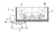
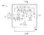
1 is a front view of a blasting apparatus according to a first embodiment of the present invention, FIG. 2 is a cross-sectional view of the blasting apparatus shown in FIG. 1 as viewed from a position AA, and FIG. 3 is a diagram of the blasting apparatus shown in FIG. 4 is a cross-sectional view of the blasting apparatus shown in FIG.
ブラスト処理装置1は、ブラスト材料Bを噴射するノズル2と、ノズル2を軌道に沿って往復移動させる移動機構3とを用いて構成することができる。図示された例では、ブラスト処理の効率が向上するように複数のノズル2がブラスト処理装置1に備えられている。各ノズル2は、ブラスト材料Bの供給ホースの先端に取り付けられる。また、ブラスト材料Bの他端は、ブラスト材料Bの供給系と接続される。但し、ブラスト材料Bの供給系及び供給ホースの図示は省略されている。 The
また、好適には、少なくともノズル2を覆うことによってブラスト材料Bの飛散を防止する防塵体4がブラスト処理装置1に備えられる。防塵体4としては、図示されるように筐体を兼ねた剛体の防塵ケースとする他、可撓性を有する防塵カバーとしてもよい。 Preferably, the
図示された例では、防塵ケースとしての防塵体4の一面側が開放されている。そして、防塵体4の開放された側からワークに向けてブラスト材料Bを噴射することができる。もちろん、ワークを筐体としての防塵体4の内部に設置するようにしてもよい。また、ワークを常に防塵体4の内部に設置する場合には、防塵効果が得られるように、防塵体4の四方の面を閉塞し、ワークの出し入れのための開閉扉を設けるようにしてもよい。 In the illustrated example, one surface side of the
一方、防塵体4のワークと逆側の面には、ブラスト処理の確認用に透明な確認窓4Aが設けられている。更に、防塵体4の底面付近には、ブラスト材料Bの供給ホースを通すための空隙4Bが設けられている。 On the other hand, a
移動機構3は、モータ5、回転体6、動力伝達機構7及び棒状部材8で構成することができる。モータ5は、移動機構3の動力源である。モータ5の出力軸5Aは、動力伝達機構7によって回転体6の回転軸6Aと連結される。そして、回転体6は、モータ5の出力を動力源とし、回転軸6Aを支点として正転と逆転とを繰返すように構成されている。従って、モータ5は、回転体6の回転軸6Aと同一直線上とならない位置に出力軸5Aを有する。 The
棒状部材8は、単一又は複数のノズル2を固定するための部材である。図示されるように複数のノズル2を水平方向に配置する場合には、長手方向が水平方向となるように棒状部材8が配置される。そして、棒状部材8は、回転体6と連結される。これにより、回転体6の支点よりも一端側が棒状部材8を介してノズル2と連結される。 The rod-shaped
棒状部材8は、回転体6に対して回転できるようにシャフトやベアリング等で連結することができる。棒状部材8を回転体6に対して回転可能に連結すれば、リンク機構が形成される。このため、回転体6の往復移動によってワイパーのように棒状部材8とともに各ノズル2を往復移動させることができる。但し、回転体6の数が1つである場合には、安定性を向上させるために棒状部材8を回転体6に固定するようにしてもよい。 The rod-shaped
一方、図示されるように、複数の棒状の回転体6を回転可能に共通の棒状部材8と連結することができる。すなわち、それぞれ対応する回転軸6Aを支点として正転と逆転とを繰返す複数の回転体6を、各支点よりも一端側で棒状部材8と連結することができる。この場合、複数の回転体6と棒状部材8とによってリンク機構が形成される。このため、移動機構3の剛性を向上させることができる。また、棒状部材8を常に水平方向に向けて往復移動させることが可能となる。 On the other hand, as shown in the drawing, a plurality of rod-shaped
尚、ノズル2を直接回転体6に固定するようにしてもよい。その場合、棒状部材8を省略することもできる。但し、ノズル2を直接回転体6に固定する場合であっても、棒状部材8で複数の回転体6を連結すれば、移動機構3の剛性を向上させることができる。 The
また、図示されるように、複数の回転体6を用いて移動機構3を構成する場合には、少なくとも1つの回転体6が動力伝達機構7によってモータ5と連結されればよい。動力伝達機構7は、モータ5の出力軸5Aの一方向の回転動力を、回転体6の正転及び逆転の繰返しのための動力として回転軸6Aに伝達するように構成される。従って、モータ5を含む構成要素によって移動機構3は、クランク機構となる。 As shown in the figure, when the moving
尚、モータ5の出力軸5Aが回転体6の回転軸6Aと同一直線上となるようにモータ5を配置しても、移動機構3を構成することができる。但し、回転体6を往復移動させるために、モータ5の出力軸5Aの回転方向を断続的に反転させることが必要となる。つまり、出力軸5Aが正転及び逆転を繰返すモータ5を回転体6の回転軸6A上に設けることが必要となる。しかしながら、モータ5の回転方向を変化させるとモータ5の消耗に繋がる。従って、モータ5の出力軸5Aを回転体6の回転軸6Aからシフトさせ、かつ動力伝達機構7によって連結する構造とすれば、モータ5の消耗を抑制することができる。 The moving
動力伝達機構7は、回転板9及び連結棒10によって構成することができる。回転板9は、モータ5の出力軸5Aに固定される。連結棒10は、回転体6の回転軸6A上とならない部分及び回転板9の回転中心以外の部分にそれぞれ回転可能に連結される。連結棒10は、回転体6に直接連結することもできる。 The
但し、図示されるように、回転体6の回転軸6Aに棒状のレバー11の一端を、回転体6とレバー11とが所定の間隔で離れた状態となるように固定し、レバー11の他端に回転可能に連結棒10を連結させれば、少なくともモータ5及び動力伝達機構7を防塵体4の外部に配置することが可能となる。すなわち、リンク機構の駆動部分を防塵体4の外部に配置することができる。このため、ブラスト材料Bの飛散による動力伝達機構7及びモータ5の目詰まりを防止することができる。 However, as shown in the drawing, one end of a rod-shaped
尚、回転板9の回転中心に関して連結棒10の連結位置と逆側における重量を、回転板9の回転によって生じる振動が抑制される重さに調整することが望ましい。すなわち、連結棒10の重量を加味した回転板9の回転中心回りの重力による回転モーメントがゼロとなるように、回転板9の重量を調節することが回転板9の振動を抑制する観点から好適である。 In addition, it is desirable to adjust the weight on the opposite side of the connecting position of the connecting
具体例として、回転板9の連結棒10が連結される側に板厚方向の複数の貫通孔を設けて回転板9の重量及び回転に必要なトルクを軽減する一方、回転板9の連結棒10が連結されない側の板厚を相対的に厚くすることによって、重力による回転モーメントを釣り合わせることができる。これにより、回転板9の振動を抑制し、かつ連結棒10の連結に用いられるベアリングの不均一な摩耗を回避することもできる。 As a specific example, a plurality of through holes in the plate thickness direction are provided on the side of the
更に、ブラスト処理装置1には、ノズル2の往復移動に伴って生じる振動を打ち消す重り12が設けられる。重り12は、回転体6の支点よりも他端側に設けられる。従って、図示されるように、複数の回転体6が設けられる場合には、重り12が、複数の回転体6の各支点よりも他端側にそれぞれ設けられる。 Further, the
重り12の重量及び位置は、回転体6の支点周りのノズル2側における重力による回転モーメントが支点周りの重り12側における重力による回転モーメント以下となるように決定される。従って、回転体6の長さを長くし、支点と重り12との距離を長くする程、重り12の重さを軽くすることができる。 The weight and position of the
原理的には、重り12の重量及び位置を、回転体6の支点周りの重力による回転モーメントがゼロとなるように決定することが最適である。但し、機械的な干渉を防止するために、回転モーメントを釣り合わせることが困難な場合には、下方の回転モーメントが上方の回転モーメントよりも大きくする方が、低重心化による安定性の向上に繋がる In principle, it is optimal to determine the weight and position of the
図示された例では、棒状の各回転体6の上方側の端部がノズル2と連結されている。従って、棒状の各回転体6の下方側の端部に円板状の重り12が固定されている。もちろん、回転体6の上方側に重り12を取付け、下方側にノズル2を連結するようにしてもよい。また、ノズル2が鉛直方向又は所望の方向に往復移動するように棒状部材8及び回転体6を配置し、回転体6の他端側に重り12を取付けるようにしてもよい。 In the illustrated example, the upper end of each rod-like
この他の移動機構3の特徴としては、移動機構3を重り12の高さが最小の時にノズル2を固定するための棒状部材8の高さが最大となるように構成することが好適である。この場合、各回転体6の長手方向が鉛直方向となって重り12が最下点に到達した時に、各回転体6の長手方向と棒状部材8の長手方向とのなす角がいずれも直角となる。従って、ノズル2を揺動させた場合に、左右の移動が対称となり、左右の移動量が均等になる。その結果、回転体6と棒状部材8との連結に用いられるベアリングの局所的な摩耗による寿命の低下を低減させることができる。 As another feature of the moving
(動作および作用)
次にブラスト処理装置1の動作および作用について説明する。(Operation and action)
Next, the operation and action of the
ブラスト処理装置1を用いてブラスト処理を行う場合には、ブラスト処理の対象となるワークのサイズや形状に応じてブラスト処理装置1自体をゴンドラ等の搬送装置に設置することができる。従って、ブラスト処理装置1を用いれば、ストリンガを取り付けた航空機のパネル等の凹凸を有し、かつ大型のワークであっても容易にブラスト処理を行うことが可能である。もちろん、ワークが小さい場合には、搬送装置を使用せずに、ブラスト処理装置1を設置してもよい。また、ワーク側を搬送装置に搭載してもよい。 When blast processing is performed using the
実際にブラスト処理を行う際には、ブラスト処理装置1のノズル2の先にワークがセットされる。或いは、逆に、ワークに合わせてブラスト処理装置1が配置される。そして、ブラスト材料Bの供給系から供給ホースを通じてブラスト材料Bが供給される。これにより、ノズル2からワークに向けてブラスト材料Bが噴射される。 When actually performing the blasting process, the work is set at the tip of the
一方、モータ5が駆動し、出力軸5Aが回転する。出力軸5Aの回転トルクは、動力伝達機構7を介して回転体6の回転軸6Aに往復回転のトルクとして伝達される。具体的には、モータ5の出力軸5Aの回転によって、回転板9が回転する。このため、回転板9と回転可能に連結された連結棒10の一端は、円状の軌跡を描いて回転移動する。他方、連結棒10の他端は、連結棒10の回転板9側における端部の位置に応じてレバー11の端部に押付力と引張力とを交互かつ周期的に負荷する。 On the other hand, the
この結果、レバー11の連結棒10側における端部は、回転軸6Aを中心とする円弧状の軌跡を往復移動することとなる。このため、レバー11の他方側の端部は、回転軸6Aとともに回転方向を周期的に変えながら所定の角度だけ回転する。従って、回転軸6Aに固定された回転体6も同様に回転軸6Aを中心として回転方向を周期的に変えながら所定の角度だけ回転する。すなわち、回転体6が往復移動する。 As a result, the end of the
回転体6が往復移動すると、回転体6に連結された棒状部材8とともにノズル2が円弧状の軌道に沿って往復移動する。また、棒状部材8と連結された、動力伝達機構7と直接連結されていない他の回転体6も、動力伝達機構7と直接連結された回転体6と同様な軌跡に沿って往復移動する。これにより、ブラスト材料Bが、ノズル2の移動範囲に応じたワークの所定の範囲に打ち付けられる。 When the
この時、ブラスト処理装置1又はワークを設置した搬送装置を駆動させ、ワークに対してノズル2を所望の方向に相対移動させることができる。例えば、ノズル2が左右端に到達する度に、ノズル2を鉛直方向に断続的にステップ移動させることができる。そうすると、ワークを広範囲に亘ってブラスト処理することができる。そして、必要な領域のブラスト処理を行うことによって、被ブラスト処理品を製造することができる。 At this time, the
尚、モータ5の回転によってノズル2が周期的に往復移動する。しかしながら、回転体6の他端には、重力による回転モーメントが釣り合うように重り12が取り付けてある。このため、ノズル2の往復移動に伴って生じる振動が打ち消される。この結果、安定的にワークのブラスト処理を行うことができる。 The
つまり以上のようなブラスト処理装置1は、ノズル2を含むブラスト材料Bの噴射部をクランク機構によって往復移動させるようにしたものである。更に、ノズル2を往復移動させる場合に生じる振動を抑制するために重り12を設けたものである。 In other words, the
(効果)
このため、ブラスト処理装置1によれば、ワークのサイズや形状にフレキシブルに適応し、かつ安定してブラスト処理することができる。すなわち、ブラスト処理装置1は、従来のように多関節アームの先にノズルを取り付けた構造ではなく、クランク機構によってノズル2を往復移動させる構造を有している。しかも、モータ5の出力を伝達するための動力伝達機構7は、防塵体4の外部に配置することができる。このため、ブラスト材料Bの飛散によって目詰まりを起こす恐れのある部位を最小限にすることができる。その結果、従来のようなノズル近傍を覆う防塵カバーや真空機構等の構成要素を不要にすることができる。これにより、凹凸のあるワークであっても容易にブラスト処理を行うことができる。(effect)
For this reason, according to the
また、ノズル2の往復移動によって生じ得る振動を重り12によって抑制することができる。すなわち、従来の多関節アームでノズルを移動させるタイプや真空引きによって防塵カバーをワークに吸着させるタイプでは、振動が生じるという問題自体が生じないが、クランク機構を採用するに当たり問題となる振動を重り12によって効果的に抑制することができる。この結果、クランク機構を用いたノズル2の往復移動が可能となる。 Further, the
そして、ノズル2の周期的な往復移動を行っても、安定的にブラスト処理を実行することができる。特に、ノズル2を高所に配置した場合における振動を大幅に抑制することが可能である。このため、ノズル2を高所に配置することが可能となる。すなわち、ノズル2を含むブラスト処理装置1を広範囲に亘って移動させることが可能となる。 The blasting process can be stably executed even when the
従って、航空機部品等の大型のワークであっても、搬送装置等によってブラスト処理装置1を広範囲に移動させることにより、容易にブラスト処理を施すことができる。つまり、ブラスト処理装置1によれば、非常に広範囲のブラスト処理が可能である。 Therefore, even a large workpiece such as an aircraft part can be easily subjected to blasting by moving the
(第2の実施形態)
図5は本発明の第2の実施形態に係るブラスト処理装置の正面図であり、図6は図5に示すブラスト処理装置の位置C-Cから見た断面図である。(Second Embodiment)
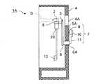
FIG. 5 is a front view of a blasting apparatus according to the second embodiment of the present invention, and FIG. 6 is a cross-sectional view of the blasting apparatus shown in FIG.
図5に示された第2の実施形態におけるブラスト処理装置1Aでは、重り12を重り制御機構20によって往復移動させるようにした点が第1の実施形態におけるブラスト処理装置1と相違する。他の構成および作用については第1の実施形態におけるブラスト処理装置1と実質的に異ならないため同一の構成については同符号を付して説明を省略する。 The blast processing apparatus 1A in the second embodiment shown in FIG. 5 is different from the
ブラスト処理装置1Aには、センサ21及び重り制御機構20が備えられる。センサ21では、ノズル2の移動方向を検出することができる。従って、センサ21には、加速度センサ等のセンサ21自体の移動方向を検出することが可能な任意のセンサが用いられる。また、センサ21は、ノズル2と共に移動する棒状部材8等の任意の部分に取り付けられる。尚、ノズル2と共に周期的に動く部分であれば、回転体6や回転軸6Aにセンサ21を取り付けるようにしてもよい。 The blast processing apparatus 1A includes a
一方、重り制御機構20は、センサ21によって検出されたノズル2の移動方向に応じて振動が打ち消される方向に重り12を移動させる装置である。従って、センサ21の出力先は、重り制御機構20と接続される。重り制御機構20は、重り12を先端に取り付けた振り子装置とすることができる。そして、重り制御機構20には、センサ21から取得した検出信号に基づいてノズル2の移動方向及び移動方向の変化を検知し、ノズル2の往復移動の周期と同等な周期で重り12をノズル2と同じ方向に移動させる機能が備えられる。 On the other hand, the
重り12の適切な最大回転角度及び移動周期は、ノズル2の移動範囲及び移動周期が既知であることから理論的又は試験によって経験的に予め求めておくことができる。従って、適切な重り12の最大回転角度及び移動周期を予め決定して重り12の制御を行うことができる。但し、重り制御機構20が加速度センサ等のセンサ21の相対位置情報や速度情報を取得して、重り12の回転角度及び移動周期を自律制御するようにしてもよい。その場合には、適切な重り12の最大回転角度及び移動周期の決定作業を省略することができる。 The appropriate maximum rotation angle and moving period of the
尚、図5には、単一の重り12及び重り制御機構20が設けられたブラスト処理装置1Aが例示されているが、複数の重り12及び重り制御機構20をブラスト処理装置1Aに設けてもよい。また、センサ21を重り制御機構20に内蔵してもよい。 5 illustrates the blast processing apparatus 1A provided with the
このような第2の実施形態におけるブラスト処理装置1Aによれば、ノズル2の往復移動に伴って生じる振動を、独立した重り12の制御によって打ち消すことができる。このため、第2の実施形態におけるブラスト処理装置1Aによれば、第1の実施形態におけるブラスト処理装置1と同様な効果を得ることができる。 According to the
(他の実施形態)
以上、特定の実施形態について記載したが、記載された実施形態は一例に過ぎず、発明の範囲を限定するものではない。ここに記載された新規な方法及び装置は、様々な他の様式で具現化することができる。また、ここに記載された方法及び装置の様式において、発明の要旨から逸脱しない範囲で、種々の省略、置換及び変更を行うことができる。添付された請求の範囲及びその均等物は、発明の範囲及び要旨に包含されているものとして、そのような種々の様式及び変形例を含んでいる。(Other embodiments)
Although specific embodiments have been described above, the described embodiments are merely examples, and do not limit the scope of the invention. The novel methods and apparatus described herein can be implemented in a variety of other ways. Various omissions, substitutions, and changes can be made in the method and apparatus described herein without departing from the spirit of the invention. The appended claims and their equivalents include such various forms and modifications as are encompassed by the scope and spirit of the invention.
1、1A ブラスト処理装置
2 ノズル
3 移動機構
4 防塵体
4A 確認窓
4B 空隙
5 モータ
5A 出力軸
6 回転体
6A 回転軸
7 動力伝達機構
8 棒状部材
9 回転板
10 連結棒
11 レバー
12 重り
20 重り制御機構
21 センサ
B ブラスト材料DESCRIPTION OF
Claims (9)
Translated fromJapanese前記複数のノズルを軌道に沿って往復移動させる移動機構と、
前記複数のノズルの往復移動に伴って生じる振動を打ち消す重りと、
を備え、
前記移動機構は、
前記複数のノズルを固定するための棒状部材と、
それぞれ対応する回転軸を支点として正転と逆転とを繰返し、各支点よりも一端側が前記棒状部材と連結される複数の回転体とを有し、
前記重りは、前記複数の回転体の前記各支点よりも他端側にそれぞれ設けられるブラスト処理装置。Aplurality of nozzles for injecting blast material;
A moving mechanism for reciprocating theplurality of nozzles along a track;
A weight that cancels vibration caused by the reciprocating movement of theplurality of nozzles;
Equipped witha,
The moving mechanism is
A rod-shaped member for fixing the plurality of nozzles;
Each of the rotating shafts corresponding to the respective fulcrum is rotated forward and reverse, and one end side of each fulcrum has a plurality of rotating bodies connected to the rod-shaped member,
The weights are respectively provided that blasting deviceon the other side of the respective support point of the plurality of rotating bodies.
前記回転軸と同一直線上とならない位置に出力軸を有するモータと、
前記出力軸と前記回転軸の少なくとも1つとを連結し、前記出力軸の一方向の回転動力を、前記回転軸の少なくとも1つの正転及び逆転の繰返しのための動力として前記回転軸の少なくとも1つに伝達する動力伝達機構と、
を更に有する請求項1乃至3のいずれか1項に記載のブラスト処理装置。The moving mechanism is
A motor having an output shaft at a position that is not collinear with the rotational shaft;
Connecting atleast one capitalof the rotary shaft and the output shaft, the rotational power in one direction of the output shaft,the rotating shaft as a power for atleast one forward and reverse rotation of the repetitionof said rotary shaft A power transmission mechanism for transmitting toat least one ;
The blast processing apparatus accordingto any one of claims1 to 3 , further comprising:
少なくとも前記モータ及び前記動力伝達機構は、前記防塵体の外部に配置される請求項4記載のブラスト処理装置。A dustproof body for preventing scattering of the blast material by covering at least theplurality of nozzles;
The blast processing apparatus according to claim4 , wherein at least the motor and the power transmission mechanism are arranged outside the dustproof body.
前記モータの出力軸に固定される回転板と、
前記複数の回転体のうちの1つ及び前記回転板の回転中心以外の部分に回転可能に連結される連結棒とを有し、
前記回転板の前記回転中心に関して前記連結棒の連結位置と逆側における重量が、前記回転板の回転によって生じる振動が抑制される重さに調整される請求項4又は5記載のブラスト処理装置。The power transmission mechanism is
A rotating plate fixed to the output shaft of the motor;
A connecting rod rotatably connected toone of theplurality of rotating bodies and a portion other than the rotation center of the rotating plate;
The blast processing apparatus according to claim4 or 5 , wherein the weight of the rotating plate on the side opposite to the connecting position of the connecting rod with respect to the rotation center of the rotating plate is adjusted to a weight that suppresses vibration caused by the rotation of the rotating plate.
移動機構を用いて前記複数のノズルを軌道に沿って往復移動させることにより被ブラスト処理品を製造するステップと、
重りを用いて前記複数のノズルの往復移動に伴って生じる振動を打ち消すステップと、
を有し、
前記移動機構は、
前記複数のノズルを固定するための棒状部材と、
それぞれ対応する回転軸を支点として正転と逆転とを繰返し、各支点よりも一端側が前記棒状部材と連結される複数の回転体とを有し、
前記重りは、前記複数の回転体の前記各支点よりも他端側にそれぞれ設けられるブラスト処理方法。Injecting blast material from aplurality of nozzles;
Producing a blasted product by reciprocating theplurality of nozzles along a trajectoryusing a moving mechanism ;
Canceling vibration caused by reciprocating movement of theplurality of nozzles using a weight;
I have a,
The moving mechanism is
A rod-shaped member for fixing the plurality of nozzles;
Each of the rotating shafts corresponding to the respective fulcrum is rotated forward and reverse, and one end side of each fulcrum has a plurality of rotating bodies connected to the rod-shaped member,
The weights are respectively provided that blasting methodto the other side of the respective support point of the plurality of rotating bodies.
Priority Applications (1)
| Application Number | Priority Date | Filing Date | Title |
|---|---|---|---|
| JP2013027739AJP6126861B2 (en) | 2013-02-15 | 2013-02-15 | Blast processing apparatus and blast processing method |
Applications Claiming Priority (1)
| Application Number | Priority Date | Filing Date | Title |
|---|---|---|---|
| JP2013027739AJP6126861B2 (en) | 2013-02-15 | 2013-02-15 | Blast processing apparatus and blast processing method |
Publications (2)
| Publication Number | Publication Date |
|---|---|
| JP2014155977A JP2014155977A (en) | 2014-08-28 |
| JP6126861B2true JP6126861B2 (en) | 2017-05-10 |
Family
ID=51577224
Family Applications (1)
| Application Number | Title | Priority Date | Filing Date |
|---|---|---|---|
| JP2013027739AActiveJP6126861B2 (en) | 2013-02-15 | 2013-02-15 | Blast processing apparatus and blast processing method |
Country Status (1)
| Country | Link |
|---|---|
| JP (1) | JP6126861B2 (en) |
Families Citing this family (7)
| Publication number | Priority date | Publication date | Assignee | Title |
|---|---|---|---|---|
| JP6426395B2 (en) | 2014-08-06 | 2018-11-21 | ブラスト工業株式会社 | Blasting apparatus and blasting method |
| CN108326754A (en)* | 2018-02-23 | 2018-07-27 | 湖南云思智能科技有限公司 | A kind of auto-delivery type liquid sandblasting machine with manipulator grabbing workpiece |
| US10674592B2 (en)* | 2018-09-27 | 2020-06-02 | Electronics And Telecommunications Research Institute | Plasma generation apparatus |
| CN112355915B (en)* | 2020-11-06 | 2024-06-18 | 东莞吉川机械科技股份有限公司 | Surface treatment device |
| CN113043174A (en)* | 2021-03-26 | 2021-06-29 | 天津英德诺机械设备有限公司 | Automatic rotatory sand blasting unit of pan |
| CN114131512B (en)* | 2021-12-09 | 2023-03-28 | 滨州职业学院 | Mechanical and electrical automation's rust cleaning equipment |
| CN116604478B (en)* | 2023-05-31 | 2025-06-24 | 中国长江电力股份有限公司 | Intelligent sand blasting room and control method thereof |
Family Cites Families (13)
| Publication number | Priority date | Publication date | Assignee | Title |
|---|---|---|---|---|
| JPS604688Y2 (en)* | 1981-07-22 | 1985-02-12 | 三井造船株式会社 | vacuum cleaner |
| JPS5914596A (en)* | 1982-07-16 | 1984-01-25 | Fukashi Uragami | Wall surface cleaner |
| JPH03196973A (en)* | 1989-12-26 | 1991-08-28 | Fuji Seiki Mach Works Ltd | Dry blasting device |
| JPH05116070A (en)* | 1991-10-30 | 1993-05-14 | Kyushu Electron Metal Co Ltd | Continuous wet type sand blast machining apparatus |
| JP3084905B2 (en)* | 1992-03-09 | 2000-09-04 | 石川島播磨重工業株式会社 | Damping device |
| US5419734A (en)* | 1993-06-28 | 1995-05-30 | Van Sickle; Jimmy L. | Sandblasting hose holder for treating upright surfaces |
| JPH09168972A (en)* | 1995-12-18 | 1997-06-30 | Hisato Yoshihara | Automatic and manual stone sculpturing device |
| US6315648B1 (en)* | 1998-03-13 | 2001-11-13 | Dana L. Neer | Apparatus for pressure treating a surface |
| JP3927812B2 (en)* | 2002-01-15 | 2007-06-13 | 株式会社 テクトリア | Injecting rotor and polishing apparatus using the same |
| JP2003291067A (en)* | 2002-03-29 | 2003-10-14 | Sinto Brator Co Ltd | Air blast processing device and air blasting method |
| NL1022293C2 (en)* | 2002-12-31 | 2004-07-15 | Tno | Device and method for manufacturing or processing optical elements and / or optical form elements, as well as such elements. |
| JP2006341504A (en)* | 2005-06-09 | 2006-12-21 | Masaomi Koriyama | Apparatus for and method of removing slope covering |
| JP2010174550A (en)* | 2009-01-30 | 2010-08-12 | Takenaka Komuten Co Ltd | Active mass damper and construction |
- 2013
- 2013-02-15JPJP2013027739Apatent/JP6126861B2/enactiveActive
Also Published As
| Publication number | Publication date |
|---|---|
| JP2014155977A (en) | 2014-08-28 |
Similar Documents
| Publication | Publication Date | Title |
|---|---|---|
| JP6126861B2 (en) | Blast processing apparatus and blast processing method | |
| JP6426395B2 (en) | Blasting apparatus and blasting method | |
| JP6005871B2 (en) | Method, processing apparatus, and processing system for automatically surface processing of large molded member of wind power generator | |
| CN102001046B (en) | Rotary table type automatic sand-blasting machine | |
| CN108326753B (en) | One kind climbing wall type shot-peening robot | |
| CN106513381A (en) | Laser cleaning device and method for axis parts | |
| CN205521383U (en) | Eight robots of planer -type | |
| CN109176321B (en) | Sandblasting equipment, sandblasting system and sandblasting method | |
| CN201815958U (en) | Turntable automatic sandblasting machine | |
| CN206811738U (en) | A four-sided grinding head for a multifunctional five-axis machine tool | |
| JP6005970B2 (en) | Blast processing apparatus and blast processing method | |
| CN203156578U (en) | Automatic shot-blast unit | |
| CN205272036U (en) | Five robots of lateral wall formula | |
| JP5721090B1 (en) | Rotating nozzle head for frame scaffold cleaning | |
| CN104827408A (en) | Working device with centripetally rotary nozzle and used for sand blasting and shot blasting | |
| CN105945675A (en) | Omni-directional robot articulated arm polishing device | |
| CN102229115B (en) | Special sandblasting machine for cylindrical part | |
| CN110405635A (en) | a sandblasting machine | |
| CN106737622B (en) | Sand blasting robot | |
| CN215357985U (en) | Novel through type sand blasting machine | |
| CN209579255U (en) | Equipment for rotor surface processing | |
| CN108638089A (en) | A kind of removing welding slag manipulator for the workshop that is welded | |
| US12427625B2 (en) | Abrasive blast treatment machine for surfaces of large-scale workpieces | |
| CN210790595U (en) | Sand blasting machine | |
| CN216138749U (en) | A sandblasting device for metal product processing |
Legal Events
| Date | Code | Title | Description |
|---|---|---|---|
| A621 | Written request for application examination | Free format text:JAPANESE INTERMEDIATE CODE: A621 Effective date:20151203 | |
| A977 | Report on retrieval | Free format text:JAPANESE INTERMEDIATE CODE: A971007 Effective date:20160915 | |
| A131 | Notification of reasons for refusal | Free format text:JAPANESE INTERMEDIATE CODE: A131 Effective date:20161004 | |
| A521 | Request for written amendment filed | Free format text:JAPANESE INTERMEDIATE CODE: A523 Effective date:20161202 | |
| TRDD | Decision of grant or rejection written | ||
| A01 | Written decision to grant a patent or to grant a registration (utility model) | Free format text:JAPANESE INTERMEDIATE CODE: A01 Effective date:20170404 | |
| A61 | First payment of annual fees (during grant procedure) | Free format text:JAPANESE INTERMEDIATE CODE: A61 Effective date:20170410 | |
| R150 | Certificate of patent or registration of utility model | Ref document number:6126861 Country of ref document:JP Free format text:JAPANESE INTERMEDIATE CODE: R150 | |
| R250 | Receipt of annual fees | Free format text:JAPANESE INTERMEDIATE CODE: R250 | |
| R250 | Receipt of annual fees | Free format text:JAPANESE INTERMEDIATE CODE: R250 | |
| R250 | Receipt of annual fees | Free format text:JAPANESE INTERMEDIATE CODE: R250 | |
| R250 | Receipt of annual fees | Free format text:JAPANESE INTERMEDIATE CODE: R250 | |
| R250 | Receipt of annual fees | Free format text:JAPANESE INTERMEDIATE CODE: R250 | |
| R250 | Receipt of annual fees | Free format text:JAPANESE INTERMEDIATE CODE: R250 |