Movatterモバイル変換


[0]ホーム

URL:


JP6124462B2 - Display input device and image forming apparatus having the same - Google Patents

Display input device and image forming apparatus having the same
Download PDF

Info

Publication number
JP6124462B2
JP6124462B2JP2014112612AJP2014112612AJP6124462B2JP 6124462 B2JP6124462 B2JP 6124462B2JP 2014112612 AJP2014112612 AJP 2014112612AJP 2014112612 AJP2014112612 AJP 2014112612AJP 6124462 B2JP6124462 B2JP 6124462B2
Authority
JP
Japan
Prior art keywords
unit
vibration
control unit
maintenance
drive signal
Prior art date
Legal status (The legal status is an assumption and is not a legal conclusion. Google has not performed a legal analysis and makes no representation as to the accuracy of the status listed.)
Expired - Fee Related
Application number
JP2014112612A
Other languages
Japanese (ja)
Other versions
JP2015227920A (en
Inventor
容子 田中
容子 田中
Current Assignee (The listed assignees may be inaccurate. Google has not performed a legal analysis and makes no representation or warranty as to the accuracy of the list.)
Kyocera Document Solutions Inc
Original Assignee
Kyocera Document Solutions Inc
Priority date (The priority date is an assumption and is not a legal conclusion. Google has not performed a legal analysis and makes no representation as to the accuracy of the date listed.)
Filing date
Publication date
Application filed by Kyocera Document Solutions IncfiledCriticalKyocera Document Solutions Inc
Priority to JP2014112612ApriorityCriticalpatent/JP6124462B2/en
Priority to CN201510272640.2Aprioritypatent/CN105278731B/en
Priority to US14/722,966prioritypatent/US9329550B2/en
Publication of JP2015227920ApublicationCriticalpatent/JP2015227920A/en
Application grantedgrantedCritical
Publication of JP6124462B2publicationCriticalpatent/JP6124462B2/en
Expired - Fee Relatedlegal-statusCriticalCurrent
Anticipated expirationlegal-statusCritical

Links

Images

Classifications

Landscapes

Description

Translated fromJapanese

本発明は表示部、タッチパネル部、タッチパネル部を振動させるための圧電素子を含む表示入力装置、及び、これを備えた画像形成装置に関する。  The present invention relates to a display unit, a touch panel unit, a display input device including a piezoelectric element for vibrating the touch panel unit, and an image forming apparatus including the display input device.

近年、表示部とタッチパネル部を重ね合わせて操作、入力を受け付ける入力装置(例えば、携帯情報端末)において、圧電素子を設けることがある。キーの表示位置をタッチする入力操作が行われたとき、圧電素子に電圧を印加し、圧電素子を変位(変形)させ、その変位に基づく振動により使用者の触覚を刺激する。圧電素子を用いることで、キーを操作したかのようなクリック感を与えることができる。  In recent years, a piezoelectric element may be provided in an input device (for example, a portable information terminal) that receives an operation and an input by superimposing a display unit and a touch panel unit. When an input operation for touching the display position of the key is performed, a voltage is applied to the piezoelectric element to displace (deform) the piezoelectric element, and the user's tactile sense is stimulated by vibration based on the displacement. By using the piezoelectric element, it is possible to give a click feeling as if the key was operated.

このような技術の一例が特許文献1に記載されている。具体的に、特許文献1には、パネルの表面に対する押圧または接触の有無を検出し、押圧または接触が検出されたときには、押圧時点または接触時点から信号波形を生成し、押圧または接触の確定後は押圧時点または接触時点から生成する信号波形よりも大きな振幅の信号波形を生成し、信号波形に従ってパネルを変位させるパネル変位手段(圧電アクチュエーター)と、を有する入力装置が記載されている。この構成により、途中で振動の大きさを変えることで、クリック感とともに、スイッチボタンを押したときのようなストローク感を体感させようとする。(特許文献1:請求項1、明細書段落[0010]等参照)。  An example of such a technique is described inPatent Document 1. Specifically,Patent Document 1 detects the presence or absence of pressing or contact with the surface of the panel. When pressing or contact is detected, a signal waveform is generated from the pressing time or the contact time, and after the pressing or contact is determined. Describes an input device having panel displacement means (piezoelectric actuator) that generates a signal waveform having a larger amplitude than the signal waveform generated from the time of pressing or contact, and displaces the panel according to the signal waveform. With this configuration, by changing the magnitude of vibration in the middle, it is possible to experience a feeling of stroke as if the switch button was pressed, together with a feeling of clicking. (See Patent Literature 1:Claim 1, paragraph [0010] of the specification, etc.).

特開2005−149197号公報JP 2005-149197 A

複合機、複写機、プリンター、ファクシミリ装置のような画像形成装置には、表示部やタッチパネル部を含む操作パネルが設けられることがある。表示部は、ジョブの設定画面を表示する。設定画面には、機能や設定項目や設定値を選択するためのキーやボタンが表示される。そして、キーの表示位置をタッチする操作(キー操作)によって、使用者は設定を行う。また、ジョブが開始されると、実行中のジョブに関する情報、メッセージを表示部に表示する場合もある。例えば、コピージョブのとき、表示部は、読取済の原稿の枚数や、印刷済の枚数などの情報や、エラーが発生した旨のメッセージ等を表示する。  An image forming apparatus such as a multifunction machine, a copier, a printer, or a facsimile machine may be provided with an operation panel including a display unit and a touch panel unit. The display unit displays a job setting screen. The setting screen displays keys and buttons for selecting functions, setting items, and setting values. Then, the user performs setting by an operation (key operation) of touching the display position of the key. In addition, when a job is started, information about a job being executed and a message may be displayed on the display unit. For example, in the case of a copy job, the display unit displays information such as the number of read documents and the number of printed documents, a message indicating that an error has occurred, and the like.

また、表示部は、使用者への注意喚起として、メンテナンスに関する情報を表示することがある。例えば、用紙やトナーの残量が少なくなってきたことをメンテナンス情報として表示する場合がある。また、交換可能なユニットの交換時期が近づくと、交換すべき部材をメンテナンス情報として表示することがある。  Moreover, a display part may display the information regarding a maintenance as alerting a user. For example, it may be displayed as maintenance information that the remaining amount of paper or toner is low. Further, when the replacement time of replaceable units approaches, a member to be replaced may be displayed as maintenance information.

見落とされないようにメンテナンス情報は表示すべきではある。しかし、表示部では、ジョブの設定画面や、実行中のジョブに関する画面に割り当てられる面積が広く、メンテナンス情報のようなメッセージを表示する領域は、狭く、且つ、端であることが多い。このため、使用者は、メンテナンス情報を見落とす場合があるという問題がある。  Maintenance information should be displayed so that it is not overlooked. However, in the display unit, the area allocated to the job setting screen and the screen related to the job being executed is wide, and the area for displaying a message such as maintenance information is often narrow and at the end. For this reason, there is a problem that the user may miss the maintenance information.

例えば、用紙残量が少ない旨のメンテナンス情報を見落したまま、多数枚の印刷を行うと、ジョブの実行中に用紙切れが生ずることが多くなる。この場合、印刷が中断されてしまう。また、トナーの残量が少なくなっている旨のメンテナンス情報を見落としたまま多数枚を印刷するジョブを実行すると、ジョブ中にトナー切れが生ずる場合がある。また、感光体ドラムや定着ユニットのような印刷に関するユニットは、在庫などの関係で注文してから使用者のもとに到着するまで時間がかかる場合がある。そして、このようなメンテナンスの時期が近いメッセージを見落して、寿命が来たユニットの注文が遅れると、しばらくの間、画像形成装置できない状態が続く場合もある。このように、メンテナンス情報の見落としがあれば、上記の弊害が生ずる。  For example, if a large number of sheets are printed while overlooking maintenance information indicating that the remaining amount of paper is low, out of paper often occurs during execution of a job. In this case, printing is interrupted. If a job for printing a large number of sheets is overlooked while overlooking maintenance information indicating that the remaining amount of toner is low, toner may run out during the job. Further, a unit related to printing, such as a photosensitive drum or a fixing unit, may take time until it arrives at the user after placing an order due to inventory. If a message about such a maintenance time is overlooked and an order for a unit that has reached the end of its life is delayed, there may be a case where the image forming apparatus cannot continue for a while. In this way, if there is an oversight of maintenance information, the above-described adverse effects occur.

更に、表示部は、メンテナンス情報のようなメッセージを表示する領域に、例えば、時刻、日時、画像形成装置の状態を示す情報など、メンテナンス情報以外の情報を表示する場合もあり、このような場合には、更に、メンテナンス情報を見落としやすくなる。  In addition, the display unit may display information other than maintenance information such as time, date and time, and information indicating the state of the image forming apparatus in an area for displaying a message such as maintenance information. Furthermore, it becomes easier to overlook maintenance information.

そのため、画像形成装置のメンテナンスを行うべき時期が近いことをメッセージとして表示するだけではなく、他の手法によってもメンテナンスすべき時期が近いことを伝達できるようにすることが望ましい。  Therefore, it is desirable not only to display as a message that the time for maintenance of the image forming apparatus is near, but also to be able to communicate that the time for maintenance is near by other methods.

なお、特許文献1記載の技術では、ストローク感を与えるために、キーの表示位置がタッチされるまでは小さな振動とし、キーの表示位置がタッチされると振動を大きくする点は記載されている。しかし、画像形成装置のメンテナンスに関する記載はない。従って、特許文献1記載の入力装置は、メンテナンス時期が近い旨のメッセージの見落としが頻発し得るものであり、上記の問題点を解決することはできない。  The technique described inPatent Document 1 describes that in order to give a feeling of stroke, the vibration is small until the key display position is touched, and the vibration is increased when the key display position is touched. . However, there is no description regarding maintenance of the image forming apparatus. Therefore, the input device described inPatent Document 1 can frequently overlook a message indicating that the maintenance time is near, and cannot solve the above problem.

本発明は上記の問題点に鑑み、複数の圧電素子によりタッチパネル部を振動(変形)させるとき、画像形成装置のメンテナンスを行うべき時期が近いことを触覚的に伝達し、使用者の注意喚起を図る。  In view of the above problems, the present invention, when vibrating (deforming) the touch panel unit with a plurality of piezoelectric elements, tactilely communicates that the time to perform maintenance of the image forming apparatus is near, and alerts the user. Plan.

上記課題解決のため請求項1に係る画像形成装置は、画面に操作、設定用のキーを表示する表示部と、前記表示部に対して設けられタッチされている位置を検知して使用者による操作を受け付けるためのタッチパネル部と、前記タッチパネル部と接する複数の圧電素子と、前記タッチパネル部の出力に基づき使用者の操作内容を認識するパネル制御部を含む操作パネルと、前記タッチパネル部を振動させるための駆動信号を前記圧電素子に入力する振動制御部と、交換、補充を行う対象であって、種類に応じたメンテナンス時期が予め定められているメンテナンス対象と前記メンテナンス時期に基づき、複数の前記メンテナンス対象のうち、メンテナンスを行うべき時期が近い要確認対象を判断する判断部と、を備え、前記振動制御部は、前記要確認対象がない状態でキー操作がなされたとき、予め定められた通常駆動信号を前記圧電素子に入力して通常振動量で前記タッチパネル部及び前記圧電素子を振動させ、前記要確認対象がある状態で予め定められたキーへの操作がなされたとき、報知用駆動信号を前記圧電素子に入力し、前記通常振動量とは異なる振動量で振動させる。  In order to solve the above problem, an image forming apparatus according to a first aspect of the present invention provides a display unit that displays operation and setting keys on a screen, and a position provided on the display unit that is touched by a user. A touch panel unit for receiving an operation, a plurality of piezoelectric elements in contact with the touch panel unit, an operation panel including a panel control unit for recognizing a user operation content based on an output of the touch panel unit, and the touch panel unit are vibrated A vibration control unit that inputs a drive signal to the piezoelectric element, an object to be replaced and replenished, and a plurality of the maintenance times based on a maintenance object in which a maintenance time corresponding to a type is predetermined and the maintenance time A determination unit that determines a target to be confirmed that is close to a time when maintenance should be performed, and the vibration control unit When a key operation is performed in a state where there is no confirmation target, a predetermined normal drive signal is input to the piezoelectric element to vibrate the touch panel unit and the piezoelectric element with a normal vibration amount, and the confirmation target is present. When a predetermined key is operated in a state, a notification drive signal is input to the piezoelectric element to vibrate with a vibration amount different from the normal vibration amount.

上述したように、本発明によれば、複数の圧電素子によりタッチパネル部を振動(変形)させるとき、メンテナンスを行うべき要確認対象があるとき、通常時とは振動量を異ならせることで、画像形成装置のメンテナンスを行うべき時期が近いことを触覚的に伝達することができる。従って、表示されたメッセージを視覚的に確認させるだけではなく、触覚的にも使用者を刺激して、注意喚起を図ることができる。  As described above, according to the present invention, when the touch panel portion is vibrated (deformed) by a plurality of piezoelectric elements, when there is a confirmation target that needs to be maintained, the amount of vibration is different from that in the normal state. It is possible to tactilely communicate that the time for maintenance of the forming apparatus is near. Therefore, not only the displayed message can be visually confirmed, but also the user can be stimulated tactilely to call attention.

複合機の一例を示す図である。1 is a diagram illustrating an example of a multifunction machine.操作パネルの一例を示す図である。It is a figure which shows an example of an operation panel.複合機のハードウェア構成の一例を示す図である。2 is a diagram illustrating an example of a hardware configuration of a multifunction peripheral. FIG.表示パネル部の構成の一例を示す図である。It is a figure which shows an example of a structure of a display panel part.各圧電素子を振動させる構成の一例を示す図である。It is a figure which shows an example of the structure which vibrates each piezoelectric element.メンテナンス対象としてのユニットを説明するための図である。It is a figure for demonstrating the unit as a maintenance object.トナー及び用紙に関するメンテナンスを説明するための図である。It is a figure for demonstrating the maintenance regarding a toner and a paper.要確認対象がないときの振動処理の流れの一例を示すフローチャートである。It is a flowchart which shows an example of the flow of a vibration process when there is no confirmation target required.要確認対象があるときの振動処理の流れの一例を示すフローチャートである。It is a flowchart which shows an example of the flow of a vibration process when there exists a confirmation target required.通常振動量と振動量を異ならせる場合の振動に関する設定画面の一例を示す。An example of the setting screen regarding a vibration in the case of changing a normal vibration amount and a vibration amount is shown.通常振動量と振動量を異ならせる場合の振動に関する設定画面の一例を示す。An example of the setting screen regarding a vibration in the case of changing a normal vibration amount and a vibration amount is shown.通常振動量と振動量を異ならせる場合の振動に関する設定画面の一例を示す。An example of the setting screen regarding a vibration in the case of changing a normal vibration amount and a vibration amount is shown.

以下、図1〜図12を用い、本発明の実施形態を説明する。以下では、複合機100(画像形成装置に相当)を例に挙げ説明する。本実施の形態に記載されている構成、配置等の各要素は、発明の範囲を限定せず、単なる説明例にすぎない。  Hereinafter, embodiments of the present invention will be described with reference to FIGS. In the following description, the multifunction peripheral 100 (corresponding to an image forming apparatus) is taken as an example. Each element such as the configuration and arrangement described in the present embodiment does not limit the scope of the invention and is merely an illustrative example.

(複合機100の全体構成)
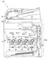
次に、図1を用いて、実施形態に係る複合機100について説明する。図1は、複合機100の一例を示す図である。
(Overall configuration of MFP 100)
Next, theMFP 100 according to the embodiment will be described with reference to FIG. FIG. 1 is a diagram illustrating an example of the multifunction peripheral 100.

図3に示すように、複合機100は、操作パネル1(詳細は後述)、原稿搬送部2aと画像読取部2bを含む。原稿搬送部2aは、搬送読取用コンタクトガラス21に向けて原稿を搬送する。また、画像読取部2bは、搬送読取用コンタクトガラス21上を通過する原稿を読み取り、原稿の画像データを生成する(搬送読取を行う)。あるいは、画像読取部2bは、載置読取用コンタクトガラス22上に載置された原稿を読み取り、原稿の画像データを生成する(載置読取を行う)。また、複合機100は、印刷部100aを備える。印刷部100aは、給紙部3a、搬送部3b、画画像形成部4、中間転写ユニット5、定着ユニット6を含む。  As shown in FIG. 3, themulti-function device 100 includes an operation panel 1 (details will be described later), adocument conveying portion 2a, and animage reading portion 2b. Thedocument transport unit 2 a transports the document toward the transportreading contact glass 21. Further, theimage reading unit 2b reads a document passing over the transportreading contact glass 21, and generates image data of the document (performs transport reading). Alternatively, theimage reading unit 2b reads a document placed on the placement readingcontact glass 22 and generates image data of the document (performs placement reading). Themultifunction device 100 includes aprinting unit 100a. Theprinting unit 100 a includes apaper feeding unit 3 a, atransport unit 3 b, an imageimage forming unit 4, anintermediate transfer unit 5, and afixing unit 6.

給紙部3aは、用紙を供給し、搬送部3bに向けて送り出す。搬送部3bは、用紙を搬送し、印刷済みの用紙を機外に排出する。画画像形成部4は、画像データに基づきトナー像を形成する。画像形成部4は、ブラックの画像形成ユニット40Bk、シアンの画像形成ユニット40C、イエローの画像形成ユニット40Y、マゼンタの画像形成ユニット40Mを含む。各画像形成ユニット40の詳細は後述する。中間転写ユニット5は、各画像形成ユニット40で形成されたトナー像の1次転写を受け、用紙に2次転写する。定着ユニット6は、用紙に転写されたトナー像を加熱および加圧して定着させる。  Thepaper feed unit 3a supplies the paper and sends it toward thetransport unit 3b. Thetransport unit 3b transports the paper and discharges the printed paper out of the apparatus. The imageimage forming unit 4 forms a toner image based on the image data. Theimage forming unit 4 includes a black image forming unit 40Bk, a cyanimage forming unit 40C, a yellowimage forming unit 40Y, and a magentaimage forming unit 40M. Details of each image forming unit 40 will be described later. Theintermediate transfer unit 5 receives the primary transfer of the toner image formed by each image forming unit 40 and performs secondary transfer onto the paper. The fixingunit 6 fixes the toner image transferred onto the paper by heating and pressing.

そして、印刷部100aは、操作パネル1でコピージョブの実行指示がなされたとき、画像読取部2bによる原稿読み取りにより得られた画像データに基づき用紙への印刷を行う(コピー機能)。あるいは、印刷部100aは、通信部74で受信された印刷用データに基づく画像を用紙に印刷する(プリンター機能)。  Then, when a copy job execution instruction is issued on theoperation panel 1, theprinting unit 100a performs printing on a sheet based on image data obtained by reading an original by theimage reading unit 2b (copy function). Alternatively, theprinting unit 100a prints an image based on the printing data received by thecommunication unit 74 on a sheet (printer function).

(操作パネル1)
次に、図1、図2を用いて、実施形態に係る操作パネル1の一例を説明する。図2は、操作パネル1の一例を示す図である。
(Operation panel 1)
Next, an example of theoperation panel 1 according to the embodiment will be described with reference to FIGS. 1 and 2. FIG. 2 is a diagram illustrating an example of theoperation panel 1.

図1に示すように、操作パネル1は、複合機100の正面上方に設けられる。操作パネル1は、表示部11とタッチパネル部12を含む表示パネル部1aを備える。表示部11は、複合機100の設定や動作指示を与え、操作するためのメニュー、画面、キー、ボタン、複合機100等の状態のメッセージなどを表示する。表示部11は、例えば、液晶表示パネルや有機EL表示パネルなどである。  As shown in FIG. 1, theoperation panel 1 is provided on the upper front side of the multifunction peripheral 100. Theoperation panel 1 includes adisplay panel unit 1 a including adisplay unit 11 and atouch panel unit 12. Thedisplay unit 11 gives settings and operation instructions for themultifunction device 100 and displays menus, screens, keys, buttons, messages about the state of themultifunction device 100, and the like for operation. Thedisplay unit 11 is, for example, a liquid crystal display panel or an organic EL display panel.

そして、表示部11の上面側に、タッチパネル部12が設けられる。タッチパネル部12は、表示部11のうち、使用者にタッチされた部分の位置(タッチ位置の座標)を検知し、使用者による操作を受け付けるためのものである。尚、タッチパネル部12としては、静電容量方式、抵抗膜方式、表面弾性波方式、赤外線方式等、各方式のものを採用でき特に制限はない。  Atouch panel unit 12 is provided on the upper surface side of thedisplay unit 11. Thetouch panel unit 12 is for detecting the position (coordinate of the touch position) of the part touched by the user in thedisplay unit 11 and accepting an operation by the user. In addition, as thetouch panel part 12, those of each method such as a capacitance method, a resistance film method, a surface acoustic wave method, an infrared method and the like can be adopted, and there is no particular limitation.

又、操作パネル1は、コピー等のジョブ開始指示用のスタートキー13や、数字入力用のテンキー部14のようなハードキーを含むハードキー配置部1bを含む。このように、操作パネル1は、タッチパネル部12やハードキー配置部1bを含み、複合機100の各機能について表示、各種設定、モード選択等を行うための表示入力装置として機能する。  Further, theoperation panel 1 includes a hardkey arrangement unit 1b including hard keys such as astart key 13 for instructing job start such as copying and anumeric keypad unit 14 for inputting numbers. As described above, theoperation panel 1 includes thetouch panel unit 12 and the hardkey arrangement unit 1b, and functions as a display input device for performing display, various settings, mode selection, and the like for each function of the multifunction peripheral 100.

(複合機100等のハードウェア構成)
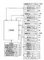
次に、図3を用いて、実施形態に係る複合機100のハードウェア構成の一例を説明する。図3は複合機100のハードウェア構成の一例を示す図である。
(Hardware configuration ofMFP 100 etc.)
Next, an example of a hardware configuration of the multifunction peripheral 100 according to the embodiment will be described with reference to FIG. FIG. 3 is a diagram illustrating an example of a hardware configuration of the multifunction peripheral 100.

まず、複合機100本体内には、主制御部7(判断部に相当)が設けられる。主制御部7は、操作パネル1、原稿搬送部2a、画像読取部2b、印刷部100a(給紙部3a、搬送部3b、画像形成部4、中間転写ユニット5、定着ユニット6)などと接続され、これらの制御を行う。  First, a main control unit 7 (corresponding to a determination unit) is provided in theMFP 100 main body. Themain control unit 7 is connected to theoperation panel 1, thedocument conveying unit 2a, theimage reading unit 2b, theprinting unit 100a (thepaper feeding unit 3a, the conveyingunit 3b, theimage forming unit 4, theintermediate transfer unit 5, and the fixing unit 6). And perform these controls.

例えば、主制御部7は、CPU71や、複合機100での処理を行うための専用回路であるASIC72等の素子を含む。CPU71は記憶部73に記憶される制御プログラムや制御用のデータに基づき演算、処理を行い、複合機100の各部を制御する。尚、主制御部7は全体制御や画像処理を行うメイン制御部や、印刷部100aを制御するエンジン制御部等、機能ごとに分割して複数種設けてもよい。  For example, themain control unit 7 includes elements such as aCPU 71 and anASIC 72 that is a dedicated circuit for performing processing in the multifunction peripheral 100. TheCPU 71 performs calculation and processing based on the control program and control data stored in thestorage unit 73 and controls each unit of the multifunction peripheral 100. Themain control unit 7 may be divided into functions and provided in a plurality of types, such as a main control unit that performs overall control and image processing, and an engine control unit that controls theprinting unit 100a.

記憶部73は、主制御部7と通信可能に接続される。記憶部73は、ROM、RAM、HDD等の記憶装置の組み合わせである。記憶部73は、複合機100の制御用プログラム、制御用データ、設定データ、画像読取部2bによって読み取られた原稿の画像データのような各種データを記憶する。又、例えば、主制御部7には画像読取部2bで原稿を読み取って得られた画像データや通信部74を介して複合機100に入力された画像データに対し、画像処理を施す画像処理部75が設けられる。画像処理部75が処理した画像データは、印刷や送信に用いられる。  Thestorage unit 73 is communicably connected to themain control unit 7. Thestorage unit 73 is a combination of storage devices such as ROM, RAM, and HDD. Thestorage unit 73 stores various data such as a control program, control data, setting data, and image data of a document read by theimage reading unit 2b. In addition, for example, themain control unit 7 performs image processing on image data obtained by reading a document by theimage reading unit 2 b and image data input to the multifunction peripheral 100 via thecommunication unit 74. 75 is provided. The image data processed by theimage processing unit 75 is used for printing and transmission.

そして、主制御部7は各種コネクタ、ソケットやFAXモデム等を備えた通信用インターフェイス部(以下、通信部74)と接続される。通信部74は、ネットワークや公衆回線等により接続された外部のコンピュータ−200(例えば、パーソナルコンピュータ−やサーバー)やFAX装置300から印刷や送信を行うためのデータ(画像データやジョブの設定に関するデータ)を受信する。また、画像読取部2bで得られた画像データをコンピュータ−200や相手方FAX装置300に送信することもできる(スキャナ機能、FAX機能)。  Themain control unit 7 is connected to a communication interface unit (hereinafter, communication unit 74) including various connectors, sockets, a FAX modem, and the like. Thecommunication unit 74 is data (image data and data related to job settings) for printing and transmission from an external computer 200 (for example, a personal computer or server) or a FAX apparatus 300 connected via a network or a public line. ). Also, the image data obtained by theimage reading unit 2b can be transmitted to the computer-200 or the counterpart FAX apparatus 300 (scanner function, FAX function).

また、主制御部7には、操作パネル1に配され、タッチパネル部12を振動させるための圧電素子9を制御する振動制御部8(圧電素子9への電圧印加や、圧電素子9の出力を検知するための圧電素子制御用回路)が設けられる。振動制御部8の詳細は、後述する。  Further, themain control unit 7 is provided with a vibration control unit 8 (controlling a voltage applied to thepiezoelectric element 9 and an output of the piezoelectric element 9), which is arranged on theoperation panel 1 and controls thepiezoelectric element 9 for vibrating thetouch panel unit 12. A piezoelectric element control circuit for detection) is provided. Details of thevibration control unit 8 will be described later.

又、操作パネル1でなされたジョブに関する設定の内容は、主制御部7に伝えられる。主制御部7は、使用者の設定にあわせてコピーのようなジョブが行われるように複合機100を制御する。操作パネル1は、パネル制御部10(認識部に相当)、ドライバー回路15、メモリー16、表示部11、タッチパネル部12を含む。パネル制御部10は、CPU10aやICなどの回路を含む。パネル制御部10は、表示部11の表示を実際に制御するドライバー回路15に指示を与え、表示部11の表示を制御する。また、パネル制御部10は、タッチパネル部12の出力を受け、タッチ位置(座標)を認識する。タッチパネル部12の出力とタッチ位置の座標の対応を示すデータはメモリー16に記憶される。パネル制御部10は、タッチ位置の座標と表示画面の画像データを比較して、画面上で選択された(押された、操作された)キーやボタンを認識する。言い換えると、パネル制御部10は、タッチパネル部12の出力と表示部11の表示に基づき、使用者の操作内容を認識する。このようにして、複合機100のコピーや送信等の各種機能における各種設定や動作指示を操作パネル1で行うことができる。  Further, the contents of the settings regarding the job made on theoperation panel 1 are transmitted to themain control unit 7. Themain control unit 7 controls the multifunction peripheral 100 so that a job such as copying is performed in accordance with the setting of the user. Theoperation panel 1 includes a panel control unit 10 (corresponding to a recognition unit), adriver circuit 15, a memory 16, adisplay unit 11, and atouch panel unit 12. Thepanel control unit 10 includes a circuit such as a CPU 10a and an IC. Thepanel control unit 10 gives an instruction to thedriver circuit 15 that actually controls the display on thedisplay unit 11 to control the display on thedisplay unit 11. Further, thepanel control unit 10 receives the output of thetouch panel unit 12 and recognizes the touch position (coordinates). Data indicating the correspondence between the output of thetouch panel unit 12 and the coordinates of the touch position is stored in the memory 16. Thepanel control unit 10 compares the coordinates of the touch position with the image data on the display screen, and recognizes a key or button selected (pressed or operated) on the screen. In other words, thepanel control unit 10 recognizes the operation content of the user based on the output of thetouch panel unit 12 and the display of thedisplay unit 11. In this way, various settings and operation instructions for various functions such as copying and transmission of the multifunction peripheral 100 can be performed on theoperation panel 1.

(表示パネル部1a)
次に、図4を用いて、表示部11や、タッチパネル部12を含む表示パネル部1aを説明する。図4は、表示パネル部1aの構成の一例を示す図である。尚、図4では、操作パネル1のうちのハードキー配置部1bの図示は省略している。
(Display panel section 1a)
Next, thedisplay panel unit 1a including thedisplay unit 11 and thetouch panel unit 12 will be described with reference to FIG. FIG. 4 is a diagram illustrating an example of the configuration of thedisplay panel unit 1a. In FIG. 4, the hardkey placement unit 1 b in theoperation panel 1 is not shown.

図4に示すように、表示パネル部1aは、タッチパネル部12を振動させるための複数の圧電素子9を含む。複数の圧電素子9は、例えば、矩形状(帯状)である。各圧電素子9は、タッチパネル部12に接するように(タッチパネル部12の裏面側に)取り付けられる。各圧電素子9はチタン酸ジルコン酸鉛などの圧電効果を有する材料で形成され、例えば、積層型のものが用いられる。  As shown in FIG. 4, thedisplay panel unit 1 a includes a plurality ofpiezoelectric elements 9 for vibrating thetouch panel unit 12. The plurality ofpiezoelectric elements 9 have, for example, a rectangular shape (band shape). Eachpiezoelectric element 9 is attached so as to be in contact with the touch panel unit 12 (on the back side of the touch panel unit 12). Eachpiezoelectric element 9 is formed of a material having a piezoelectric effect such as lead zirconate titanate, and for example, a laminated type is used.

又、タッチパネル部12の裏面側には、タッチパネル部12と所定の間隔を設けつつ、表示部11が配置される。タッチパネル部12は、表示部11に表示された画面、画像を透過する。例えば、タッチパネル部12には、透明のプラスチック板やガラス板が用いられる。又、各圧電素子9は、タッチパネル部12の下側(表示部11の側)の面に取り付けられる(上側の面に取り付けられても良い)。例えば、各圧電素子9は接着剤、両面テープなどによりタッチパネル部12に取り付けられる。  Further, thedisplay unit 11 is disposed on the back side of thetouch panel unit 12 while providing a predetermined distance from thetouch panel unit 12. Thetouch panel unit 12 transmits a screen and an image displayed on thedisplay unit 11. For example, a transparent plastic plate or a glass plate is used for thetouch panel unit 12. Eachpiezoelectric element 9 is attached to the lower surface (thedisplay unit 11 side) of the touch panel unit 12 (may be attached to the upper surface). For example, eachpiezoelectric element 9 is attached to thetouch panel unit 12 with an adhesive, a double-sided tape, or the like.

又、化粧ケース17には、開口17a(操作窓)が設けられている。開口17aは、矩形状であり、タッチパネル部12のうち、開口17aに応じた矩形の領域は、外部に露出する。この露出部分が使用者から(外部から)視認でき、使用者によりタッチされ得る領域(タッチ可能領域12a)となる。また、表示部11のうち、開口17aに対応する領域が使用者に視認される部分となる。使用者は、タッチ可能領域12aに映る表示部11のキー等の表示位置をタッチして、所望の機能や設定項目について設定を行う。一方、タッチパネル部12のうち、化粧ケース17により隠され、外部から視認できず(視認されず)、使用者によりタッチされない領域(外周縁領域12b)に各圧電素子9が取り付けられる。  Thedecorative case 17 is provided with anopening 17a (operation window). Theopening 17a has a rectangular shape, and a rectangular area corresponding to theopening 17a in thetouch panel unit 12 is exposed to the outside. This exposed portion becomes a region (touchable region 12a) that can be visually recognized from the user (from the outside) and can be touched by the user. Moreover, the area | region corresponding to theopening 17a becomes a part visually recognized by the user among thedisplay parts 11. FIG. The user touches a display position such as a key of thedisplay unit 11 displayed in thetouchable area 12a to set a desired function or setting item. On the other hand, eachpiezoelectric element 9 is attached to a region (outerperipheral region 12 b) of thetouch panel portion 12 that is hidden by thedecorative case 17, cannot be visually recognized from the outside (not visually recognized), and is not touched by the user.

また、タッチパネル部12、圧電素子9、表示部11には、化粧ケース17が被せられる。化粧ケース17とタッチパネル部12の間には、埃やゴミの進入を防ぐシール材18が挟まれる。  Thetouch panel unit 12, thepiezoelectric element 9, and thedisplay unit 11 are covered with adecorative case 17. Between thedecorative case 17 and thetouch panel unit 12, a sealing material 18 that prevents entry of dust and dirt is sandwiched.

(各圧電素子9、タッチパネル部12の振動)
次に、図5を用いて、実施形態に係る操作パネル1での各圧電素子9とタッチパネル部12の振動を説明する。図5は、各圧電素子9を振動させる構成の一例を示す図である。
(Vibration of eachpiezoelectric element 9 and touch panel unit 12)
Next, the vibration of eachpiezoelectric element 9 and thetouch panel unit 12 on theoperation panel 1 according to the embodiment will be described with reference to FIG. FIG. 5 is a diagram illustrating an example of a configuration for vibrating eachpiezoelectric element 9.

図5に示すように、本実施形態の圧電素子9は、タッチパネル部12の上下左右の辺に対し、それぞれ1つずつ配される。そして、タッチパネル部12の各端辺から予め定められた長さだけ内側であって、各辺の中央に対して90度のラインと、圧電素子9の中心が重なるように各圧電素子9が配される。尚、各圧電素子9の配置の手法は上記に限られず、別の態様で配置してもよい。  As shown in FIG. 5, onepiezoelectric element 9 of the present embodiment is arranged for each of the upper, lower, left and right sides of thetouch panel unit 12. Then, eachpiezoelectric element 9 is arranged so that a line of 90 degrees with respect to the center of each side is overlapped with the center of each side by a predetermined length from each end side of thetouch panel unit 12. Is done. In addition, the arrangement | positioning method of eachpiezoelectric element 9 is not restricted above, You may arrange | position in another aspect.

そして、振動制御部8は、制御回路81(制御IC)、入力電圧調整部82、スイッチング部83を含む。制御回路81は、各圧電素子9への電圧印加のON/OFFを制御する。入力電圧調整部82は、各圧電素子9に入力する駆動信号用の直流電圧を生成する回路であり、電圧の大きさを変えることができる。スイッチング部83は、各圧電素子9への電圧印加のON/OFFを行うためのスイッチング素子であり、制御回路81の指示に基づき、ON/OFFを行い、その結果、パルス信号が各圧電素子9に入力される。  Thevibration control unit 8 includes a control circuit 81 (control IC), an inputvoltage adjustment unit 82, and aswitching unit 83. Thecontrol circuit 81 controls ON / OFF of voltage application to eachpiezoelectric element 9. The inputvoltage adjusting unit 82 is a circuit that generates a DC voltage for a drive signal input to eachpiezoelectric element 9 and can change the magnitude of the voltage. The switchingunit 83 is a switching element for performing ON / OFF of voltage application to eachpiezoelectric element 9, and performs ON / OFF based on an instruction from thecontrol circuit 81, and as a result, a pulse signal is transmitted to eachpiezoelectric element 9. Is input.

主制御部7が交換、補充の時期が近いメンテナンス対象(詳細は後述)がないと判断している状態でキー操作がなされたとき、制御回路81は、通常駆動信号S1を各圧電素子9に入力させる。具体的に、通常駆動信号S1を入力するとき、制御回路81は、入力電圧調整部82に予め定められた大きさ(振幅)のに直流電圧を生成させる。尚、入力電圧調整部82は、制御回路81の指示に応じた電圧を出力するコンバーターである。そして、制御回路81は、予め定められた入力期間(例えば、0.5秒程度)の間に、予め定められた周波数で各圧電素子9への電圧印加のON/OFFをスイッチング部83に行わせる。この通常駆動信号S1の入力による圧電素子9の形状変化によって、圧電素子9及びこれに接するタッチパネル部12が通常振動量で振動する。この振動によって、クリックしたような操作感を与えることができる。  When a key operation is performed in a state where themain control unit 7 determines that there is no maintenance target (details will be described later) for replacement and replenishment, thecontrol circuit 81 sends a normal drive signal S1 to eachpiezoelectric element 9. Let them enter. Specifically, when the normal drive signal S1 is input, thecontrol circuit 81 causes the inputvoltage adjustment unit 82 to generate a DC voltage having a predetermined magnitude (amplitude). The inputvoltage adjustment unit 82 is a converter that outputs a voltage according to an instruction from thecontrol circuit 81. Then, thecontrol circuit 81 performs ON / OFF of the voltage application to eachpiezoelectric element 9 at a predetermined frequency during a predetermined input period (for example, about 0.5 seconds). Make it. Due to the change in the shape of thepiezoelectric element 9 due to the input of the normal drive signal S1, thepiezoelectric element 9 and thetouch panel unit 12 in contact with thepiezoelectric element 9 vibrate with a normal vibration amount. This vibration can give an operational feeling like clicking.

そして、本実施形態の操作パネル1では、各圧電素子9とタッチパネル部12の振動量を変えることができる。言い換えると、振動の大きさや振動する時間を通常振動量と異ならせることができる。主制御部7が交換、補充の時期が近いメンテナンス対象(詳細は後述)があると判断している状態でキー操作がなされたとき、制御回路81は、通常振動量とは異なる振動量となる報知用駆動信号S2を各圧電素子9に入力する(場合がある)。例えば、圧電素子9は、印加される電圧の大小に応じて圧電素子9の変形量が変わる点に着目し、入力電圧調整部82は、圧電素子9に入力する駆動信号の電圧の振幅(大きさ)を通常駆動信号S1と異ならせる。  And in theoperation panel 1 of this embodiment, the vibration amount of eachpiezoelectric element 9 and thetouch panel part 12 can be changed. In other words, the magnitude of vibration and the vibration time can be made different from the normal vibration amount. When a key operation is performed in a state where themain control unit 7 determines that there is a maintenance target (details will be described later) for replacement and replenishment, thecontrol circuit 81 has a vibration amount different from the normal vibration amount. The notification drive signal S2 is input to each piezoelectric element 9 (in some cases). For example, thepiezoelectric element 9 pays attention to the fact that the deformation amount of thepiezoelectric element 9 changes depending on the magnitude of the applied voltage, and the inputvoltage adjustment unit 82 determines the amplitude (large) of the voltage of the drive signal input to thepiezoelectric element 9. Is different from the normal drive signal S1.

また、圧電素子9には、共振周波数のような振動が最も大きくなる周波数が存在する。そこで、制御回路81は、各圧電素子9への電圧印加のON期間とOFF期間の長さを調整することで(スイッチング部83のスイッチング周波数を調整することで)、各圧電素子9に入力する通常駆動信号S1の周波数と報知用駆動信号S2の周波数を異ならせてもよい。また、制御回路81は、通常駆動信号S1と報知用駆動信号S2で各圧電素子9に入力するパルス数やパルスを入力する時間の長さを異ならせて、振動している時間を異ならせてもよい。  Further, thepiezoelectric element 9 has a frequency such as a resonance frequency at which the vibration is greatest. Therefore, thecontrol circuit 81 adjusts the length of the ON period and the OFF period of voltage application to each piezoelectric element 9 (by adjusting the switching frequency of the switching unit 83), and inputs it to eachpiezoelectric element 9. The frequency of the normal drive signal S1 may be different from the frequency of the notification drive signal S2. In addition, thecontrol circuit 81 varies the number of pulses input to eachpiezoelectric element 9 and the length of time for inputting the pulses by using the normal drive signal S1 and the notification drive signal S2 to vary the vibration time. Also good.

このように、振動制御部8は、各圧電素子9に入力する駆動信号の波形を、通常駆動信号S1と報知用駆動信号S2とで異ならせる(調整する)ことで、各圧電素子9とタッチパネル部12の振動量を制御できる。  As described above, thevibration control unit 8 varies (adjusts) the waveform of the drive signal input to eachpiezoelectric element 9 between the normal drive signal S1 and the notification drive signal S2, thereby adjusting eachpiezoelectric element 9 and the touch panel. The amount of vibration of theunit 12 can be controlled.

(メンテナンス対象としてのユニット)
次に、図1、図6を用いて、メンテナンス対象としてのユニットを説明する。図6は、メンテナンス対象としてのユニットを説明するための図である。尚、各色の画像形成ユニット40は同様の構成である。
(Units subject to maintenance)
Next, a unit as a maintenance target will be described with reference to FIGS. FIG. 6 is a diagram for explaining a unit as a maintenance target. Each color image forming unit 40 has the same configuration.

本実施形態の複合機100では、印刷関連のユニットのうち、複数のユニットを交換することができる。各ユニットの寿命には差があるので、寿命が来たユニットごとに交換することができる。これにより、複合機100の寿命を全体的に延ばすことができる。本実施形態の複合機100では、ドラムユニット4a、現像ユニット4b、中間転写ユニット5、定着ユニット6などを交換することができる。これらのユニットがメンテナンス対象である。  In theMFP 100 according to the present embodiment, a plurality of units among the printing-related units can be exchanged. Since there is a difference in the life of each unit, it can be replaced for each unit that has reached the end of its life. Thereby, the lifetime of the multifunction peripheral 100 can be extended as a whole. In the multifunction peripheral 100 of this embodiment, thedrum unit 4a, the developingunit 4b, theintermediate transfer unit 5, the fixingunit 6 and the like can be replaced. These units are subject to maintenance.

ドラムユニット4aは、各色の画像形成ユニット40に含まれるユニットであり、感光体ドラム41を含む。感光体ドラム41の表面には、静電潜像が形成され、感光体ドラム41は、静電潜像をトナーで現像したトナー像を担持する。また、ドラムユニット4aは、感光体ドラム41を回転させるためのギア列や感光体ドラム41を支持する筐体などを含む。  Thedrum unit 4 a is a unit included in the image forming unit 40 for each color and includes aphotosensitive drum 41. An electrostatic latent image is formed on the surface of thephotosensitive drum 41, and thephotosensitive drum 41 carries a toner image obtained by developing the electrostatic latent image with toner. Thedrum unit 4 a includes a gear train for rotating thephotosensitive drum 41, a housing that supports thephotosensitive drum 41, and the like.

現像ユニット4bは、各色の画像形成ユニット40に含まれる。トナーの色ごとに、計4つの現像ユニット4bが設けられる。現像ユニット4bは、トナーを感光体ドラム41に飛翔させ、感光体ドラム41周面の静電潜像をトナーで現像するため、トナーを担持する部材や、現像ユニット4b内のトナーを攪拌する部材や各種回転体を回転させるギア列などを含む。  The developingunit 4b is included in the image forming unit 40 for each color. A total of four developingunits 4b are provided for each toner color. The developingunit 4b causes the toner to fly to thephotosensitive drum 41, and develops the electrostatic latent image on the circumferential surface of thephotosensitive drum 41 with the toner. Therefore, the developingunit 4b is a member that carries the toner and a member that stirs the toner in the developingunit 4b. And a gear train that rotates various rotating bodies.

中間転写ユニット5は、中間転写ベルト51や1次転写ローラー52を含む。中間転写ユニット5は中間転写ベルト51を回転させ、1次転写ローラー52に電圧を印加し、各感光体ドラム41で形成されたトナー像を重ね合わせつつ中間転写ベルト51に1次転写する。そして、中間転写ユニット5は、2次転写ローラー53を含み、2次転写ローラー53に電圧を印加し、中間転写ベルト51上のトナー像を用紙に2次転写する。また、中間転写ユニット5はこれらの部材を支持するフレームや各種回転体を回転させるギア列などを含む。  Theintermediate transfer unit 5 includes anintermediate transfer belt 51 and aprimary transfer roller 52. Theintermediate transfer unit 5 rotates theintermediate transfer belt 51, applies a voltage to theprimary transfer roller 52, and primarily transfers the toner images formed on thephotosensitive drums 41 to theintermediate transfer belt 51 while superimposing them. Theintermediate transfer unit 5 includes asecondary transfer roller 53, applies a voltage to thesecondary transfer roller 53, and secondarily transfers the toner image on theintermediate transfer belt 51 to a sheet. Theintermediate transfer unit 5 includes a frame that supports these members, a gear train that rotates various rotating bodies, and the like.

定着ユニット6は、トナーを加熱する加熱ローラー61、加熱ローラー61に圧接してニップを形成する加圧ローラー62を含む。定着ユニット6は、加熱ローラー61と加圧ローラー62のニップに用紙を通過させ、用紙にトナー像を定着させる。加熱ローラー61を熱するため、ヒーターや通電スイッチや温度センサーや過昇温防止回路などを含むヒーターユニット63も定着ユニット6に設けられる。また、定着ユニット6は、これらの部材を支持するフレームや各種回転体を回転させるギア列などを含む。  The fixingunit 6 includes aheating roller 61 that heats the toner, and apressure roller 62 that presses theheating roller 61 to form a nip. The fixingunit 6 passes the paper through the nip between theheating roller 61 and thepressure roller 62 and fixes the toner image on the paper. In order to heat theheating roller 61, aheater unit 63 including a heater, an energization switch, a temperature sensor, an excessive temperature rise prevention circuit and the like is also provided in the fixingunit 6. The fixingunit 6 includes a frame that supports these members, a gear train that rotates various rotating bodies, and the like.

そして、各ユニット(ドラムユニット4a、現像ユニット4b、中間転写ユニット5、定着ユニット6)には、それぞれ印刷耐用枚数(印刷できる枚数)が予め定められる。印刷耐用枚数は、各ユニットのメンテナンス時期(交換時期)を定めたものである。各ユニットの印刷耐用枚数は、画質や摩耗の程度などを考慮して適宜定められる。例えば、ドラムユニット4aと中間転写ユニット5の印刷耐用枚数は、50万ページ、現像ユニット4bや定着ユニット6は25万ページのように定められる。これらの各ユニットの印刷耐用枚数を定めたデータ(印刷耐用枚数データD1)が記憶部73に記憶される。  Each unit (thedrum unit 4a, the developingunit 4b, theintermediate transfer unit 5, and the fixing unit 6) has a predetermined printing durability (number of printable sheets). The number of prints that can be printed is determined by the maintenance time (replacement time) of each unit. The printing endurance number of each unit is appropriately determined in consideration of the image quality and the degree of wear. For example, the durable printing number of thedrum unit 4a and theintermediate transfer unit 5 is set to 500,000 pages, and the developingunit 4b and the fixingunit 6 are set to 250,000 pages. Data (print life count data D 1) that defines the print life count of each unit is stored in thestorage unit 73.

そして、主制御部7は、各ユニットについて、使用開始から(取り付けられてから)、現在までの印刷枚数の累計印刷枚数を示すデータ(累計印刷枚数データD2)を記憶部73に記憶させる。例えば、主制御部7は、1ページ印刷するごとに、印刷で用いたユニットの累計印刷枚数を示すデータを更新させる。例えば、白黒印刷のときブラックのドラムユニット4a、現像ユニット4bは使用するが、ブラック以外の色のドラムユニット4a、現像ユニット4bは用いない。この場合、ブラックのドラムユニット4a、現像ユニット4bについてのみ累計印刷枚数の値を増やす。あるいは、主制御部7は、ジョブが完了するごとに、そのジョブで印刷した枚数分、印刷で用いたユニットの累計印刷枚数のカウントを増やす。  Then, themain control unit 7 causes thestorage unit 73 to store data indicating the total number of printed sheets from the start of use (after being attached) to each unit (total number of printed sheets data D2). For example, each time one page is printed, themain control unit 7 updates data indicating the total number of printed sheets of the unit used for printing. For example, theblack drum unit 4a and the developingunit 4b are used for monochrome printing, but thedrum unit 4a and the developingunit 4b for colors other than black are not used. In this case, the value of the total number of printed sheets is increased only for theblack drum unit 4a and the developingunit 4b. Alternatively, each time the job is completed, themain control unit 7 increases the count of the total number of printed sheets of the unit used for printing by the number of sheets printed by the job.

更に、主制御部7は、印刷耐用枚数と累計印刷枚数に基づき、各ユニットのうち、寿命が近いため交換時期が近づいており、メンテナンスを行うべき時期が近いユニット(要確認対象)の有無を判断する。具体的には、主制御部7は、印刷耐用枚数から累計印刷枚数を引いて得られる枚数が、予め定められた基準枚数を下回っているユニットを、要確認対象と判断する。基準枚数は、適宜定めることができる。例えば、残り2000枚というように具体的な枚数でもよいし、各ユニットの印刷耐用枚数に5%を乗じて得られる枚数のように、印刷耐用枚数に所定の比率を乗じて得られる枚数でもよい。各ユニットの基準枚数を示すデータ(基準枚数データD3)は、記憶部73に記憶される。  Further, themain control unit 7 determines whether or not there is a unit (required confirmation target) whose maintenance time is approaching and maintenance is near due to the near end of life, based on the print endurance number and the cumulative number of prints. to decide. Specifically, themain control unit 7 determines that a unit whose number obtained by subtracting the cumulative number of printed sheets from the printable number of sheets is less than a predetermined reference number is a confirmation target. The reference number can be determined as appropriate. For example, a specific number such as the remaining 2000 sheets may be used, or a number obtained by multiplying the printing durability number by a predetermined ratio, such as a number obtained by multiplying the printing durability number of each unit by 5%. . Data indicating the reference number of each unit (reference number data D3) is stored in thestorage unit 73.

例えば、ユニットを交換したサービスマンが操作パネル1に対して入力を行うことにより、主制御部7は、ユニット交換がなされたこと、交換されたユニットを認識する。この場合、操作パネル1は、ユニットの交換がなされた旨の入力を受け付ける。そして、主制御部7は、交換されたユニットの累計印刷枚数をリセットする。  For example, when the service person who exchanged the unit inputs to theoperation panel 1, themain control unit 7 recognizes that the unit has been exchanged and the exchanged unit. In this case, theoperation panel 1 receives an input indicating that the unit has been replaced. Then, themain control unit 7 resets the cumulative number of printed sheets of the replaced unit.

また、主制御部7は、ユニットのうち、要確認対象のものがあるとき、そのユニットの交換時期が近づいている旨のメッセージを表示部11に表示させる。表示部11は、左下隅や右下隅などの限られた領域にメッセージを表示する。  Further, when there is a unit to be confirmed among the units, themain control unit 7 causes thedisplay unit 11 to display a message indicating that the replacement time of the unit is approaching. Thedisplay unit 11 displays a message in a limited area such as the lower left corner or the lower right corner.

(メンテナンス対象としての給紙部3a、トナーコンテナ42、廃トナー容器44)
次に、図1、図7を用いて、トナー及び用紙に関するメンテナンスを説明する。図7は、トナー及び用紙に関するメンテナンスを説明するための図である。尚、図1では、便宜上、トナーコンテナ42と廃トナー容器44の図示を省略している。
(Feeding unit 3a,toner container 42,waste toner container 44 as maintenance targets)
Next, maintenance related to toner and paper will be described with reference to FIGS. FIG. 7 is a diagram for explaining maintenance related to toner and paper. In FIG. 1, thetoner container 42 and thewaste toner container 44 are not shown for convenience.

主制御部7は、トナーや用紙に関するメンテナンスを行うべき時期が近づいているか否かも判断する。複合機100は、トナーに関する部分として、トナーコンテナ42、トナー補給機構43、廃トナー容器44、廃トナー搬送部45、を含む。このうち、トナーコンテナ42や廃トナー容器44がメンテナンス対象である。また、複合機100は、用紙の給紙を行う部分であり、メンテナンス対象としての給紙部3aを含む。  Themain control unit 7 also determines whether or not the maintenance time for toner and paper is approaching. The multifunction peripheral 100 includes atoner container 42, atoner supply mechanism 43, awaste toner container 44, and a wastetoner transport unit 45 as parts related to toner. Among these, thetoner container 42 and thewaste toner container 44 are maintenance targets. Themultifunction machine 100 is a part that feeds paper, and includes apaper feed unit 3a as a maintenance target.

トナーに関し、各色の現像ユニット4bに対して、トナーコンテナ42(トナーコンテナ42)が設けられる(計4つ)。各トナーコンテナ42は、対応する現像ユニット4bが形成するトナー像の色(ブラック、シアン、イエロー、マゼンタの何れか1色)のトナーを収容する。そして、各トナーコンテナ42は、現像ユニット4bにトナーを補給する。トナーコンテナ42から現像ユニット4bにトナーを送るためトナー補給機構43が設けられる。トナー補給機構43は、トナーを現像ユニット4bに向けて搬送する補給スクリュー43aや、補給スクリュー43aを回転させる補給用モーター43bを含む。主制御部7は、補給用モーター43b及び補給スクリュー43aを回転させ、トナーを補給させる。  Regarding the toner, toner containers 42 (toner containers 42) are provided for the developingunits 4b of the respective colors (a total of four). Eachtoner container 42 stores toner of the color of the toner image (any one of black, cyan, yellow, and magenta) formed by the corresponding developingunit 4b. Eachtoner container 42 supplies toner to the developingunit 4b. Atoner replenishing mechanism 43 is provided to send toner from thetoner container 42 to the developingunit 4b. Thetoner replenishing mechanism 43 includes a replenishingscrew 43a that conveys toner toward the developingunit 4b and a replenishingmotor 43b that rotates the replenishingscrew 43a. Themain control unit 7 rotates thereplenishment motor 43b and thereplenishment screw 43a to replenish the toner.

そして、各トナーコンテナ42には、トナーコンテナ42内のトナーの残量を検知するためのトナー残量センサー46が設けられる。主制御部7は、トナー残量センサー46の出力に基づき、各トナーコンテナ42に残るトナーの量を認識する。尚、トナー残量センサー46には、光センサーや磁気センサーや圧力センサーなどを用いることができ、用いるトナーの特性を考慮したセンサーが用いられる。また、主制御部7は、トナーコンテナ42が取り付けられてから原稿の画像データに対してトナーをのせるドットを累計的にカウントし、累計のドットカウントに基づきトナーの残量を認識、推定するようにしてもよい。  Eachtoner container 42 is provided with a toner remainingamount sensor 46 for detecting the remaining amount of toner in thetoner container 42. Themain control unit 7 recognizes the amount of toner remaining in eachtoner container 42 based on the output of the toner remainingamount sensor 46. As the toner remainingamount sensor 46, an optical sensor, a magnetic sensor, a pressure sensor, or the like can be used, and a sensor that takes into account the characteristics of the toner to be used is used. Themain control unit 7 cumulatively counts the number of dots on which the toner is applied to the image data of the document after thetoner container 42 is attached, and recognizes and estimates the remaining amount of toner based on the cumulative dot count. You may do it.

更に、主制御部7は、認識した各トナーコンテナ42内のトナーの残量に基づき、各トナーコンテナ42のうち、トナーの残量が少ないため、メンテナンスを行うべき時期(交換時期)が近いトナーコンテナ42(要確認対象)の有無を判断する。具体的には、主制御部7は、トナー残量センサー46の出力に基づき、トナーコンテナ42内のトナーが予め定められたトナー残量を下回ったトナーコンテナ42を要確認対象と認識する。例えば主制御部7は、残り10%を下回っているトナーコンテナ42を要確認対象と判断する。  Further, themain control unit 7 determines that the maintenance time (replacement time) is close because the remaining toner amount is small in eachtoner container 42 based on the recognized remaining toner amount in eachtoner container 42. The presence / absence of the container 42 (confirmation target required) is determined. Specifically, themain control unit 7 recognizes thetoner container 42 in which the toner in thetoner container 42 falls below a predetermined toner remaining amount as a confirmation target based on the output of the toner remainingamount sensor 46. For example, themain control unit 7 determines that thetoner container 42 that is less than the remaining 10% is a confirmation target.

尚、主制御部7は、トナーコンテナ42が取り付けられてからの印刷枚数を累計的にカウントし、累計印刷枚数が一定値を超えているトナーコンテナ42を要確認対象と認識してもよい。この場合、主制御部7は、検知される残量が所定の値以上増えた色のトナーコンテナ42が交換されたと認識する。交換したトナーコンテナ42の色の入力が操作パネル1になされたとき、主制御部7は、その色のトナーコンテナ42が交換されたと認識してもよい。  Themain control unit 7 may cumulatively count the number of printed sheets after thetoner container 42 is attached, and may recognize thetoner container 42 whose accumulated number of printed sheets exceeds a certain value as a confirmation target. In this case, themain control unit 7 recognizes that thecolor toner container 42 whose detected remaining amount has increased by a predetermined value or more has been replaced. When the color of the replacedtoner container 42 is input to theoperation panel 1, themain control unit 7 may recognize that thetoner container 42 of that color has been replaced.

また、中間転写ユニット5の中間転写ベルト51や感光体ドラム41上のトナーは、全て転写されず、残る場合がある。残ったトナーは次のトナー像形成の邪魔になる。そこで、本実施形態の複合機100には、感光体ドラム41や中間転写ベルト51に残るトナーを除去するクリーニングユニット47、54(図1参照)が設けられる。主制御部7は、除去されたトナーを廃トナーとして廃トナー容器44に向けて廃トナー搬送部45に搬送させる。廃トナー搬送部45は、廃トナーを送る搬送用スクリュー45aや、搬送用スクリュー45aを回転させる廃トナーモーター45bを含む。主制御部7は、印刷ジョブ中や印刷ジョブ後、一定時間の間、廃トナーモーター45b及び搬送用スクリュー45aを回転させ、廃トナー容器44に向けて廃トナーを送る。  Further, all the toner on theintermediate transfer belt 51 and thephotosensitive drum 41 of theintermediate transfer unit 5 may not be transferred and may remain. The remaining toner interferes with the next toner image formation. Therefore, the multifunction peripheral 100 according to the present embodiment is provided with cleaningunits 47 and 54 (see FIG. 1) that remove toner remaining on thephotosensitive drum 41 and theintermediate transfer belt 51. Themain control unit 7 transports the removed toner as waste toner toward thewaste toner container 44 to the wastetoner transport unit 45. The wastetoner conveyance unit 45 includes aconveyance screw 45a for sending waste toner and a waste toner motor 45b for rotating theconveyance screw 45a. Themain control unit 7 rotates the waste toner motor 45 b and the conveyingscrew 45 a for a predetermined time during the print job or after the print job, and sends the waste toner toward thewaste toner container 44.

そして、廃トナー容器44に対して、廃トナー容器44内の廃トナーの量を検知する(廃トナー容器44に収容される廃トナーが一定量を超えたか否かを検知する)ための廃トナーセンサー48が設けられる。廃トナー容器44の収容量には限界があり、廃トナーがこぼれると機内を汚すので、こぼれるほど廃トナー容器44に廃トナーが溜まる前に廃トナー容器44の交換を促す必要がある。主制御部7は、廃トナーセンサー48の出力に基づき、廃トナー容器44内の廃トナーの量を認識する。尚、トナー残量センサー46には、廃トナー容器44内の積み上げられた廃トナーの高さを検知するセンサー(例えば、光センサー)などを用いることができる。  Then, waste toner for detecting the amount of waste toner in the waste toner container 44 (detecting whether or not the amount of waste toner contained in thewaste toner container 44 exceeds a certain amount) with respect to thewaste toner container 44. Asensor 48 is provided. The capacity of thewaste toner container 44 is limited, and if the waste toner is spilled, the inside of the apparatus is soiled. Therefore, it is necessary to promote the replacement of thewaste toner container 44 before the waste toner is collected in thewaste toner container 44. Themain control unit 7 recognizes the amount of waste toner in thewaste toner container 44 based on the output of thewaste toner sensor 48. As the toner remainingamount sensor 46, a sensor (for example, an optical sensor) that detects the height of the accumulated waste toner in thewaste toner container 44 can be used.

更に、主制御部7は、認識した廃トナーセンサー48の出力に基づき、廃トナー容器44内の廃トナーの量が一定量を超えており、満杯が近いため、メンテナンスを行うべき時期(交換時期)が近いか否かを判断する。  Furthermore, themain control unit 7 determines the time when maintenance should be performed because the amount of waste toner in thewaste toner container 44 exceeds a certain amount based on the recognized output of thewaste toner sensor 48 and is almost full. ) Is close.

尚、各ユニットやトナーコンテナ42と同様に、主制御部7は、廃トナー容器44が取り付けられてからの印刷枚数を累計的にカウントし、累計印刷枚数が一定値を超えているとき、廃トナー容器44を要確認対象と認識してもよい。この場合、主制御部7は、廃トナー容器44内の廃トナーの量が一定量でなくなったことに基づき、廃トナー容器44が交換されたと認識する。また、廃トナー容器44を交換した旨の入力がなされたとき、主制御部7は、廃トナー容器44が交換されたと認識してもよい。As with each unit andtoner container 42, themain control unit 7 cumulatively counts the number of printed sheets after thewaste toner container 44 is attached, and when the total number of printed sheets exceeds a certain value, Thetoner container 44 may be recognized as a confirmation target. In this case, themain control unit 7 recognizes that thewaste toner container 44 has been replaced based on the fact that the amount of waste toner in thewaste toner container 44 is no longer constant. Further, when an input indicating that thewaste toner container 44 has been replaced is made, themain control unit 7 may recognize that thewaste toner container 44 has been replaced.

次に、用紙に関するメンテナンスを説明する。給紙部3aは、印刷に用いる用紙を収容する。例えば、500枚程度の用紙を収容する。尚、複数の給紙部3aを積み重ねて給紙部3aを増設することで、数千枚の用紙を収容することもできる。そして、給紙部3aには、用紙の残量を検知するための用紙残量センサー31が設けられる。  Next, maintenance related to paper will be described. Thepaper feed unit 3a accommodates paper used for printing. For example, about 500 sheets are accommodated. It should be noted that several thousands of sheets can be accommodated by stacking a plurality ofsheet feeding units 3a and adding thesheet feeding unit 3a. Thepaper feed unit 3a is provided with a paper remainingamount sensor 31 for detecting the remaining amount of paper.

主制御部7は、用紙残量センサー31の出力に基づき、給紙部3a(給紙カセット)に残る用紙の量を認識する。尚、用紙残量センサー31には、用紙の積載方向(上下方向)に並べた複数の光センサーなどを用いることができ、用紙の残量を認識できればよい。  Themain control unit 7 recognizes the amount of paper remaining in thepaper feed unit 3 a (paper feed cassette) based on the output of the paper remainingamount sensor 31. It should be noted that a plurality of optical sensors arranged in the paper stacking direction (vertical direction) can be used for the paper remainingamount sensor 31 as long as the remaining amount of paper can be recognized.

更に、主制御部7は、認識した用紙残量に基づき、メンテナンスを行うべき時期(用紙の補充時期)が近いか否かを判断する。具体的に、主制御部7は、用紙残量センサー31の出力に基づき、残量が予め定められた用紙残量を下回ったと認識したとき、給紙部3aを要確認対象と認識する。例えば、主制御部7は、残り10%を下回っていると、給紙部3aを要確認対象と判断する。  Further, themain control unit 7 determines whether or not it is time to perform maintenance (paper replenishment time) based on the recognized remaining paper amount. Specifically, when themain control unit 7 recognizes that the remaining amount falls below a predetermined remaining sheet amount based on the output of the remainingsheet sensor 31, themain control unit 7 recognizes thesheet feeding unit 3a as a confirmation target. For example, if the remaining 10% is less than the remaining 10%, themain control unit 7 determines that thesheet feeding unit 3a is a confirmation target.

また、主制御部7は、給紙部3a、各トナーコンテナ42、廃トナー容器44のうち、要確認対象があるとき、用紙の補充、又は、交換時期が近づいている旨のメッセージを表示部11に表示させる。表示部11は、左下隅や右下隅などの限られた領域にメッセージを表示する。  Themain control unit 7 also displays a message indicating that the time for replenishment or replacement of paper is approaching when there is a confirmation target among thepaper supply unit 3a, eachtoner container 42, andwaste toner container 44. 11 is displayed. Thedisplay unit 11 displays a message in a limited area such as the lower left corner or the lower right corner.

(要確認対象がないときの振動処理)
次に、図8を用いて、要確認対象がないときの振動処理の流れを説明する。図8は、要確認対象がないときの振動処理の流れの一例を示すフローチャートである。
(Vibration processing when there is no confirmation required)
Next, the flow of vibration processing when there is no confirmation target will be described with reference to FIG. FIG. 8 is a flowchart illustrating an example of the flow of vibration processing when there is no confirmation target.

図8のスタートでは、主制御部7は、各ユニット(ドラムユニット4a、現像ユニット4b、中間転写ユニット5、定着ユニット6)、各色のトナーコンテナ42、廃トナー容器44、給紙部3aといったメンテナンス対象のうち、要確認対象がないと判断している状態である。  At the start of FIG. 8, themain control unit 7 performs maintenance on each unit (drumunit 4a, developingunit 4b,intermediate transfer unit 5, fixing unit 6),toner container 42 for each color,waste toner container 44, andpaper feeding unit 3a. Of these, it is determined that there is no confirmation target.

まず、パネル制御部10は、タッチパネル部12の出力と表示している画面のデータに基づき、表示部11に表示されたキーに対する操作がなされたか否かを確認する(ステップ♯11)。パネル制御部10は、キー操作がなされるまで確認を続ける(ステップ♯11のNo→ステップ♯11)  First,panel control unit 10 confirms whether or not an operation has been performed on the key displayed ondisplay unit 11 based on the output oftouch panel unit 12 and the displayed screen data (step # 11).Panel control unit 10 continues checking until a key operation is performed (No instep # 11 → step # 11).

キー操作がなされたとき(ステップ♯11のYes)、パネル制御部10は、主制御部7にキー操作がなされた旨を伝える(ステップ♯12)。この旨を受けて、振動制御部8は、予め定められた通常駆動信号S1を各圧電素子9に入力する(ステップ♯13)。  When a key operation is performed (Yes in step # 11), thepanel control unit 10 notifies themain control unit 7 that the key operation has been performed (step # 12). In response to this, thevibration control unit 8 inputs a predetermined normal drive signal S1 to each piezoelectric element 9 (step # 13).

通常駆動信号S1は、パルス信号である。また、通常駆動信号S1の振幅、パルス信号の周波数、入力するパルス数、通常駆動信号S1を入力する時間の長さ、キー操作がなされてから通常駆動信号S1の入力を開始するまでの時間などが予め定められている。この通常駆動信号S1を示すデータ(通常駆動信号データD4)は、記憶部73に記憶されている。振動制御部8は、通常駆動信号データD4に示される波形の信号を各圧電素子9に入力する。その結果、各圧電素子9やタッチパネル部12は通常振動量で振動する。通常駆動信号S1は、使用者にクリック感を与えるような波形である。そして、フローは終了し、ステップ♯11から再び開始される(ステップ♯13の後、ステップ♯11に戻るともいえる)。  The normal drive signal S1 is a pulse signal. Further, the amplitude of the normal drive signal S1, the frequency of the pulse signal, the number of pulses to be input, the length of time for inputting the normal drive signal S1, the time from when the key operation is performed until the input of the normal drive signal S1 is started, etc. Is predetermined. Data indicating the normal drive signal S1 (normal drive signal data D4) is stored in thestorage unit 73. Thevibration control unit 8 inputs a signal having a waveform indicated by the normal drive signal data D4 to eachpiezoelectric element 9. As a result, eachpiezoelectric element 9 and thetouch panel unit 12 vibrate with a normal vibration amount. The normal drive signal S1 has a waveform that gives a click feeling to the user. Then, the flow ends and starts again from step # 11 (it can be said that the process returns to step # 11 after step # 13).

(要確認対象があるときの振動処理)
次に、図9〜図12を用いて、要確認対象があるときの振動処理の流れを説明する。図9は、要確認対象があるときの振動処理の流れの一例を示すフローチャートである。図10〜図12は、通常振動量と振動量を異ならせる場合の振動に関する設定画面の一例を示す。
(Vibration processing when there is a confirmation target)
Next, the flow of vibration processing when there is a target to be confirmed will be described with reference to FIGS. FIG. 9 is a flowchart illustrating an example of the flow of vibration processing when there is a confirmation target. 10 to 12 show examples of setting screens related to vibration when the normal vibration amount and the vibration amount are different.

図9のスタートでは、主制御部7は、各ユニット(ドラムユニット4a、現像ユニット4b、中間転写ユニット5、定着ユニット6)、各色のトナーコンテナ42、廃トナー容器44、給紙部3aといったメンテナンス対象のうち、要確認対象があると判断している状態である。言い換えると、主制御部7が、補充、交換の時期が近いメンテナンス対象があると判断している状態である。  At the start of FIG. 9, themain control unit 7 performs maintenance on each unit (drumunit 4a, developingunit 4b,intermediate transfer unit 5, fixing unit 6),toner container 42 for each color,waste toner container 44, andpaper feeding unit 3a. Among these, it is in a state where it is determined that there is a confirmation target. In other words, themain control unit 7 is in a state where it is determined that there is a maintenance object whose replenishment and replacement timing are close.

まず、パネル制御部10は、タッチパネル部12の出力と表示している画面のデータに基づき、表示部11に表示されたキーに対する操作がなされたか否かを確認する(ステップ♯21)。パネル制御部10は、キー操作がなされるまで確認を続ける(ステップ♯21のNo→ステップ♯21)  First,panel control unit 10 confirms whether or not an operation has been performed on the key displayed ondisplay unit 11 based on the output oftouch panel unit 12 and the displayed screen data (step # 21).Panel control unit 10 continues checking until a key operation is performed (No instep # 21 → step # 21).

キー操作がなされたとき(ステップ♯21のYes)、パネル制御部10は、主制御部7に操作されたキー(キーの種類)を伝える(ステップ♯22)。そして、主制御部7は、操作されたキーに基づき、通常振動量と異なる振動量で振動させるか否かを判断する(ステップ♯23)。  When a key operation is performed (Yes in Step # 21), thepanel control unit 10 informs themain control unit 7 of the operated key (key type) (Step # 22). Then, themain control unit 7 determines whether to vibrate with a vibration amount different from the normal vibration amount based on the operated key (step # 23).

ここで、本実施形態の複合機100では、表示部11に表示されるキーのうち、要確認対象がある状態でどのようなキーが操作されると、振動量を通常と異ならせるかを予め定めておくことができる。図10を用いて、この点を説明する。  Here, in theMFP 100 according to the present embodiment, among the keys displayed on thedisplay unit 11, which key is operated in a state where there is a confirmation target is required to determine in advance whether the vibration amount is different from the normal amount. It can be determined. This point will be described with reference to FIG.

図10は、要確認対象がある状態での振動を設定するための画面(第1振動設定画面SC1)である。第1振動設定画面SC1は、操作パネル1に対して所定の操作が行われると、パネル制御部10は、表示部11に表示させる。  FIG. 10 is a screen (first vibration setting screen SC1) for setting vibration in a state where there is a confirmation target. Thepanel control unit 10 causes thedisplay unit 11 to display the first vibration setting screen SC1 when a predetermined operation is performed on theoperation panel 1.

図10の第1振動設定画面SC1の第1の項目に配されたキーを操作することにより、要確認対象がある状態でどのようなキーが操作されると、圧電素子9やタッチパネル部12の振動量を通常と異ならせるかを定めることができる。  By operating the keys arranged in the first item of the first vibration setting screen SC1 in FIG. 10, which key is operated in a state where there is a confirmation target, thepiezoelectric element 9 and thetouch panel unit 12 It is possible to determine whether the amount of vibration is different from normal.

図10の第1振動設定画面SC1の第1の項目のうち、左側の第1選択キーK1が操作されると、パネル制御部10は、要確認対象がある状態で、予め定められた特定キーが操作されたときのみ、圧電素子9やタッチパネル部12の振動量を通常と異ならせる(報知用駆動信号S2を各圧電素子9に入力する)設定がなされたと認識する。  When the first selection key K1 on the left side of the first items on the first vibration setting screen SC1 in FIG. 10 is operated, thepanel control unit 10 determines a specific key that is set in advance in a state where there is a confirmation target. Only when the button is operated, it is recognized that the vibration amount of thepiezoelectric element 9 and thetouch panel unit 12 is set to be different from normal (the notification drive signal S2 is input to each piezoelectric element 9).

特定キーは、メンテナンス対象(要確認対象)ごとに、適宜定めることができる。例えば、給紙部3aに対しては、用紙の設定に関するキーを特定キーと定めることができる。例えば、印刷に用いる用紙サイズの設定項目を選択するためのキーが、給紙部3aの特定キーとされてもよい。また、用紙サイズの設定項目を選択すると表示される用紙サイズ選択画面内に配された用紙サイズ(設定値)を選択するためのキー(例えば、「A4」や「レター」の文字を含むキー)が給紙部3aの特定キーとされてもよい。また、給紙部3aに収容されている用紙のサイズと一致する文字を含むキー(例えば、「A4」サイズが収容されているとき、「A4」の文字を含むキー)が給紙部3aの特定キーとされてもよい。尚、給紙部3aには収容される用紙のサイズを自動的に検知するための用紙サイズセンサー32を設けることができる(図7参照)。主制御部7は、用紙サイズセンサー32の出力に基づき、給紙部3a内の用紙のサイズを認識する。このように、用紙の設定に関するキーを給紙部3aに対する特定キーとし、通常振動量と振動量が異なったときに直前に操作したキーの種類によって、給紙部3aや用紙に関するメンテナンス対象が要確認対象であると使用者に類推させることができる。  The specific key can be appropriately determined for each maintenance target (confirmation target required). For example, for thepaper feed unit 3a, a key relating to paper setting can be determined as a specific key. For example, a key for selecting a setting item for the paper size used for printing may be a specific key of thepaper feed unit 3a. In addition, a key for selecting a paper size (setting value) arranged in a paper size selection screen displayed when a paper size setting item is selected (for example, a key including characters “A4” and “letter”). May be a specific key of thesheet feeding unit 3a. In addition, a key including characters that match the size of the paper stored in thepaper supply unit 3a (for example, a key including the characters “A4” when the “A4” size is stored) is included in thepaper supply unit 3a. It may be a specific key. Thepaper feed unit 3a can be provided with apaper size sensor 32 for automatically detecting the size of the stored paper (see FIG. 7). Themain control unit 7 recognizes the size of the paper in thepaper supply unit 3 a based on the output of thepaper size sensor 32. As described above, the key relating to the paper setting is set as a specific key for thepaper feeding unit 3a, and the maintenance target relating to thepaper feeding unit 3a and the paper is required depending on the type of the key operated immediately before the normal vibration amount and the vibration amount are different. The user can be inferred to be the confirmation target.

また、トナーコンテナ42、廃トナー容器44に対しては、色の設定に関するキーやトナーに関するキーを特定キーと定めることができる。例えば、印刷物の色の設定項目を選択するためのキーや、各トナーコンテナ42のトナー残量を示す画面を表示させるためのキーがトナーコンテナ42や廃トナー容器44の特定キーとされてもよい。また、印刷物の色を定めるためのキー(カラー印刷を行うかモノクロ印刷を行うか)がトナーコンテナ42や廃トナー容器44の特定キーとされてもよい。あるいは、要確認対象となっているトナーコンテナ42の色と同じ意味合いを有するキー(例えば、ブラックのトナーコンテナ42が要確認対象のとき、黒やブラックの文字を含むキーや、黒色で塗りつぶされたキー)が、トナーコンテナ42や廃トナー容器44の特定キーとされてもよい。このように、トナーに関するキーをトナーコンテナ42や廃トナー容器44に対する特定キーとし、通常振動量と振動量が異なったときに直前に操作したキーの種類によって、トナーコンテナ42や廃トナー容器44が要確認対象であると使用者に類推させることができる。  For thetoner container 42 and thewaste toner container 44, a key relating to color setting and a key relating to toner can be determined as specific keys. For example, a key for selecting a setting item for the color of the printed material or a key for displaying a screen indicating the remaining amount of toner in eachtoner container 42 may be the specific key for thetoner container 42 or thewaste toner container 44. . A key for determining the color of the printed material (whether color printing or monochrome printing is performed) may be used as a specific key for thetoner container 42 or thewaste toner container 44. Alternatively, a key having the same meaning as the color of thetoner container 42 to be confirmed (for example, when theblack toner container 42 is to be confirmed, a key including black or black characters or a black color) Key) may be a specific key for thetoner container 42 and thewaste toner container 44. As described above, the key relating to the toner is used as a specific key for thetoner container 42 and thewaste toner container 44, and thetoner container 42 and thewaste toner container 44 are changed depending on the type of the key operated immediately before the normal vibration amount and the vibration amount are different. The user can be inferred that it is a confirmation target.

また、各ユニット(ドラムユニット4a、現像ユニット4b、中間転写ユニット5、定着ユニット6)に対しては、画質の設定に関するキーや、印刷画質のための調整に関するキーを特定キーと定めることができる。例えば、印刷の濃度を設定するためのキーが、各ユニットの特定キーとされてもよい。また、感光体ドラム41に意図的にトナーをのせてトナーに含まれる研磨剤によるリフレッシュ処理に関するキーが、ドラムユニット4aの特定キーと設定されてもよい。現像ユニット4bに印加する電圧の調整を行うためのキーが現像ユニット4bの特定キーとされてもよい。また、位置ずれや色ずれを確認するために中間転写ベルト51にトナー像を転写させるキャリブレーション処理に関するキーが、中間転写ユニット5の特定キーと設定されてもよい。また、印刷時の加熱ローラー61の温度の設定に関するキーが定着ユニット6の特定キーと設定されてもよい。このように、印刷プロセスや、印刷プロセスの調整に関するキーを各ユニットに対する特定キーとし、通常振動量と振動量が異なったときに直前に操作したキーの種類によって、要確認対象となっているユニットを使用者に類推させることができる。  For each unit (drumunit 4a, developingunit 4b,intermediate transfer unit 5, fixing unit 6), a key relating to image quality setting and a key relating to adjustment for printing image quality can be determined as specific keys. For example, a key for setting the printing density may be a specific key of each unit. Further, a key relating to the refresh process by the abrasive contained in the toner by intentionally putting the toner on thephotosensitive drum 41 may be set as a specific key of thedrum unit 4a. A key for adjusting the voltage applied to the developingunit 4b may be a specific key of the developingunit 4b. In addition, a key relating to a calibration process for transferring a toner image to theintermediate transfer belt 51 in order to confirm a positional shift or a color shift may be set as a specific key of theintermediate transfer unit 5. Further, a key related to the setting of the temperature of theheating roller 61 during printing may be set as a specific key of the fixingunit 6. In this way, the key related to the printing process and the adjustment of the printing process is a specific key for each unit, and the unit that needs to be checked depending on the type of key operated immediately before when the normal vibration amount and vibration amount differ Can be analogized by the user.

一方で、図10の第1振動設定画面SC1の第1の項目のうち、右側の第2選択キーK2が操作されると、パネル制御部10は、要確認対象がある状態では、表示部11に表示されたキーの何れのキーが操作されても、圧電素子9やタッチパネル部12の振動量を通常と異ならせる(報知用駆動信号S2を圧電素子9に入力する)設定がなされたと認識する。  On the other hand, when the second selection key K2 on the right side among the first items on the first vibration setting screen SC1 in FIG. 10 is operated, thepanel control unit 10 displays thedisplay unit 11 in a state where there is a confirmation target. Regardless of which of the keys displayed on the screen is operated, it is recognized that the vibration amount of thepiezoelectric element 9 or thetouch panel unit 12 is set differently from normal (the notification drive signal S2 is input to the piezoelectric element 9). .

これら特定キーのみか、全てのキーかの設定に基づき、主制御部7は、操作されたキーに基づき、通常振動量と異なる振動量で振動させるか否かを判断する(ステップ♯23)。特定キーが操作されたときのみ通常振動量と異なる振動量とする設定がなされているとき、主制御部7は、操作されたキーが現在の要確認対象に対応する特定キーであれば、通常振動量と異なる振動量で振動させると判断し(ステップ♯23のYes)、操作されたキーが現在の要確認対象に対応する特定キー以外のキーであれば、通常振動量で振動させると判断する(ステップ♯23のNo)。また、何れのキーが操作されても、圧電素子9やタッチパネル部12の振動量を通常と異ならせる設定がなされているとき、主制御部7は、通常振動量と異なる振動量で振動させると判断する(ステップ♯23のYes)。  Based on the setting of only these specific keys or all the keys, themain controller 7 determines whether or not to vibrate with a vibration amount different from the normal vibration amount based on the operated key (step # 23). When the setting is made such that the vibration amount is different from the normal vibration amount only when the specific key is operated, themain control unit 7 is normal if the operated key is the specific key corresponding to the current confirmation target. It is determined to vibrate with a vibration amount different from the vibration amount (Yes in step # 23), and if the operated key is a key other than the specific key corresponding to the current confirmation target, it is determined to vibrate with the normal vibration amount. (No in step # 23). In addition, when any key is operated, when themain control unit 7 vibrates with a vibration amount different from the normal vibration amount when the vibration amount of thepiezoelectric element 9 or thetouch panel unit 12 is set to be different from the normal vibration amount. Judgment is made (Yes in step # 23).

通常振動量で振動させると判断したとき(ステップ♯23のNo)、主制御部7は、各圧電素子9に、予め定められた通常駆動信号S1を振動制御部8に入力させる(ステップ♯24)。そして、フローは終了し、ステップ♯21から再び開始される(ステップ♯24の後、ステップ♯21に戻るともいえる)。  When it is determined to vibrate with the normal vibration amount (No in step # 23), themain control unit 7 causes eachpiezoelectric element 9 to input a predetermined normal drive signal S1 to the vibration control unit 8 (step # 24). ). Then, the flow ends and starts again from step # 21 (it can be said that the process returns to step # 21 after step # 24).

報知用駆動信号S2で振動させると判断したとき(ステップ♯23のNo)、主制御部7は、各圧電素子9に、通常駆動信号S1とは波形が異なる報知用駆動信号S2を振動制御部8に入力させる(ステップ♯25)。そして、フローは終了し、ステップ♯21から再び開始される(ステップ♯25の後、ステップ♯21に戻るともいえる)。  When it is determined to vibrate with the notification drive signal S2 (No in step # 23), themain control unit 7 applies a notification drive signal S2 having a waveform different from that of the normal drive signal S1 to eachpiezoelectric element 9 to the vibration control unit. 8 (step # 25). Then, the flow ends and starts again from step # 21 (it can be said that the process returns to step # 21 after step # 25).

ここで、本実施形態の複合機100では、報知用駆動信号S2を圧電素子9に入力するとき(通常と振動量を異ならせるとき)の振動量を設定することができる。この点を、図10〜図12を用いて説明する。  Here, in themultifunction machine 100 of the present embodiment, the vibration amount when the notification drive signal S2 is input to the piezoelectric element 9 (when the vibration amount is different from the normal amount) can be set. This point will be described with reference to FIGS.

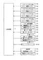
まず、本実施形態の複合機100では、複数のメンテナンス対象をグループ分けすることができる。パネル制御部10は、図10に示す第1振動設定画面SC1に配された有キーK3に対する操作がなされると、各メンテナンス対象をグループ分けする旨の設定がなされたと認識する。  First, in theMFP 100 according to the present embodiment, a plurality of maintenance targets can be grouped. Thepanel control unit 10 recognizes that the setting for grouping the maintenance targets has been made when an operation is performed on the key K3 arranged on the first vibration setting screen SC1 shown in FIG.

有りキーの下方には、複数のメンテナンス対象が上下方向に並べて表示される。そして、各メンテナンス対象に対し、属するグループを設定するためのチェックボックスC1C1が設けられる。メンテナンス対象1つにつき、チェックボックスC1が3つなので、本実施形態の複合機100では、メンテナンス対象を3つのグループに分けることができる。このように、タッチパネル部12は、各メンテナンス対象をグループ分けする入力を受け付け、パネル制御部10は、タッチパネル部12の出力に基づき、各メンテナンス対象が属するグループを認識する。  Below the presence key, a plurality of maintenance objects are displayed side by side in the vertical direction. A check box C1C1 for setting a group to which each maintenance target belongs is provided. Since there are three check boxes C1 for each maintenance target, the maintenance target can be divided into three groups in theMFP 100 of the present embodiment. As described above, thetouch panel unit 12 receives an input for grouping each maintenance target, and thepanel control unit 10 recognizes the group to which each maintenance target belongs based on the output of thetouch panel unit 12.

図10に示す例では、要確認対象となる頻度(交換や補充の頻度)が最も高い用紙補充(給紙部3a)をグループ1に、要確認対象となる頻度(交換や補充の頻度)が中程度のトナーコンテナ42や廃トナー容器44をグループ2に、要確認対象となる頻度(交換や補充の頻度)が低い各ユニット(ドラムユニット4a、現像ユニット4b、中間転写ユニット5、定着ユニット6)をグループ3とする例を示している。  In the example shown in FIG. 10, the paper replenishment (feeding unit 3a) having the highest frequency to be confirmed (frequency of replacement or replenishment) is assigned togroup 1, and the frequency to be confirmed (frequency of replacement or replenishment). Each unit (drumunit 4a, developingunit 4b,intermediate transfer unit 5, fixing unit 6) with a low frequency (replacement or replenishment frequency) that is a subject of confirmation in thegroup 2 for themedium toner container 42 and thewaste toner container 44. Shows an example in which agroup 3 is used.

グループ分けをする設定で第1振動設定画面SC1の次へキーK5が操作されると、パネル制御部10は、図11に示す第2振動設定画面SC2を表示部11に表示させる。第2振動設定画面SC2では、並べられたチェックボックスC2にチェックをいれることで、グループ単位で振動量の大きさを設定することができる。なお、第2振動設定画面SC2では、通常振動量よりも3段階まで振動量を大きく又は小さくできる(計6段階)例を示しているが、更に多段階でもよい。  When the key K5 is operated next to the first vibration setting screen SC1 in the grouping setting, thepanel control unit 10 causes thedisplay unit 11 to display the second vibration setting screen SC2 shown in FIG. On the second vibration setting screen SC2, the magnitude of the vibration amount can be set for each group by checking the check boxes C2 arranged. Note that the second vibration setting screen SC2 shows an example in which the vibration amount can be increased or decreased up to three steps (total six steps) from the normal vibration amount, but may be further multi-stepped.

各段階での報知用駆動信号S2の波形を示すデータ(報知用駆動信号データD5)は、記憶部73に記憶されている。主制御部7は、各圧電素子9に対し、記憶部73に記憶された報知用駆動信号データD5と、第2設定画面で設定された段階に基づいた報知用駆動信号S2を振動制御部8に入力させる。  Data indicating the waveform of the notification drive signal S2 at each stage (notification drive signal data D5) is stored in thestorage unit 73. For eachpiezoelectric element 9, themain control unit 7 transmits the notification drive signal data D5 stored in thestorage unit 73 and the notification drive signal S2 based on the stage set on the second setting screen to thevibration control unit 8. To input.

振動制御部8は、報知用駆動信号S2と通常駆動信号S1とで、振幅のみを変化させることで振動量を異ならせるようにしてもよい。この場合、振動制御部8は、通常駆動信号S1の振幅と報知用駆動信号S2の振幅を異ならせる。そして、振動制御部8は、振動量が大きい段階ほど振幅が大きい波形の報知用駆動信号S2を、振動量が小さい段階ほど振幅が小さい波形の報知用駆動信号S2を各圧電素子9に入力する。  Thevibration control unit 8 may vary the amount of vibration by changing only the amplitude between the notification drive signal S2 and the normal drive signal S1. In this case, thevibration control unit 8 makes the amplitude of the normal drive signal S1 different from the amplitude of the notification drive signal S2. Then, thevibration control unit 8 inputs to each piezoelectric element 9 a notification driving signal S2 having a waveform with a larger amplitude as the amount of vibration increases, and a notification driving signal S2 having a waveform with a smaller amplitude as the amount of vibration decreases. .

また、振動制御部8は、報知用駆動信号S2と通常駆動信号S1とで、パルス信号の周波数のみを変化させることで振動量を異ならせるようにしてもよい。この場合、振動制御部8は、通常駆動信号S1の周波数と報知用駆動信号S2の周波数を異ならせる。そして、振動制御部8は、振動量が大きい段階ほど圧電素子9の固有振動数に近い周波数の報知用駆動信号S2を、振動量が小さい段階ほど圧電素子9の固有振動数から遠い周波数の報知用駆動信号S2を各圧電素子9に入力する。  Further, thevibration control unit 8 may vary the amount of vibration by changing only the frequency of the pulse signal between the notification drive signal S2 and the normal drive signal S1. In this case, thevibration control unit 8 changes the frequency of the normal drive signal S1 and the frequency of the notification drive signal S2. Then, thevibration control unit 8 notifies the notification drive signal S2 having a frequency closer to the natural frequency of thepiezoelectric element 9 as the vibration amount increases, and notifies the frequency farther from the natural frequency of thepiezoelectric element 9 as the vibration amount decreases. Drive signal S2 is input to eachpiezoelectric element 9.

また、振動制御部8は、報知用駆動信号S2と通常駆動信号S1とで、パルス信号を入力する時間(入力するパルスの個数)のみを変化させることで振動量を異ならせるようにしてもよい。この場合、振動制御部8は、通常駆動信号S1を入力する時間の長さと、報知用駆動信号S2を入力する時間の長さを異ならせる。また、振動制御部8は、振動量が大きい段階ほどパルス信号の入力時間が長い報知用駆動信号S2を、振動量が小さい段階ほどパルス信号の入力時間が短い報知用駆動信号S2を各圧電素子9に入力する。  Further, thevibration control unit 8 may vary the vibration amount by changing only the time (number of pulses to be input) for inputting the pulse signal between the notification drive signal S2 and the normal drive signal S1. . In this case, thevibration control unit 8 varies the length of time for inputting the normal drive signal S1 and the length of time for inputting the notification drive signal S2. In addition, thevibration control unit 8 generates a notification drive signal S2 having a longer pulse signal input time as the vibration amount is larger, and a notification drive signal S2 having a shorter pulse signal input time as the vibration amount is smaller. 9

また、振幅、周波数、信号を入力する時間の長さの長短の複数を組み合わせて、報知用駆動信号S2の波形と通常駆動信号S1の波形を異ならせるようにしてもよい。  Further, the waveform of the notification drive signal S2 and the waveform of the normal drive signal S1 may be made different by combining a plurality of amplitudes, frequencies, and lengths of time for inputting signals.

そして、図11に示す第2振動設定画面SC2は、要確認対象となる頻度(交換や補充の頻度)が最も高いグループ1を振動量が最も小さい段階に設定し、要確認対象となる頻度が最も低いグループ3を振動量が最も大きい段階に設定し、要確認対象となる頻度(交換や補充の頻度)が中程度のグループ2を、グループ3よりは振動量が小さく、通常駆動信号S1よりは振動量が大きい段階に設定した例を示している。振動量の大小の関係は、グループ1<グループ2<グループ3となる。  Then, the second vibration setting screen SC2 shown in FIG. 11 sets thegroup 1 having the highest frequency (replacement and replenishment frequency) to be confirmed as the stage where the vibration amount is the smallest, and the frequency to be confirmed. Thelowest group 3 is set at the stage where the vibration amount is the largest, and thegroup 2 having a medium frequency (replacement and replenishment frequency) to be confirmed is smaller than thegroup 3, and the vibration amount is smaller than that of the normal drive signal S1. Shows an example in which the amount of vibration is set to a large level. The relationship between the magnitudes of vibration amounts isgroup 1 <group 2 <group 3.

また、逆に、要確認対象となる頻度が最も高いグループ1ほど、振動量が大きくなるように設定してもよい。また、どのグループも、通常振動量よりも振動量が大きくなるように設定してもよいし、通常振動量よりも振動量が小さくなるように設定してもよい。このように、パネル制御部10は、複数のメンテナンス対象をグループに分ける設定を認識する。そして、振動制御部8は、グループごとに報知用駆動信号S2の波形を異ならせ、グループごとに振動量を異ならせる。尚、全て又は2つのグループの振動量が同じになるように設定してもよい。  Conversely, the vibration amount may be set so as to increase in thegroup 1 having the highest frequency to be confirmed. Further, any group may be set so that the vibration amount is larger than the normal vibration amount, or may be set so that the vibration amount is smaller than the normal vibration amount. In this way, thepanel control unit 10 recognizes a setting for dividing a plurality of maintenance targets into groups. Thevibration control unit 8 varies the waveform of the notification drive signal S2 for each group, and varies the vibration amount for each group. In addition, you may set so that the vibration amount of all or two groups may become the same.

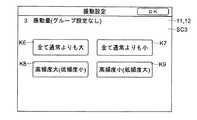
また、本実施形態の複合機100では、複数のメンテナンス対象をグループ分けせずに、要確認対象があるときの報知用駆動信号S2を設定することができる。具体的に、パネル制御部10は、図10に示す第1振動設定画面SC1に配された無キーK4に対する操作がなされると、各メンテナンス対象をグループしない旨の設定がなされたと認識する。  Further, in theMFP 100 according to the present embodiment, the notification drive signal S2 when there is a confirmation target can be set without grouping a plurality of maintenance targets. Specifically, thepanel control unit 10 recognizes that the setting indicating that the maintenance targets are not grouped is made when an operation is performed on the no-key K4 arranged on the first vibration setting screen SC1 illustrated in FIG.

グループ分けをしない設定で第1振動設定画面SC1の次へキーK5が操作されると、パネル制御部10は、図12に示す第3振動設定画面SC3を表示部11に表示させる。第3振動設定画面SC3では、要確認対象があるときの振動量を4種の中から選択することができる。  When the key K5 is operated next to the first vibration setting screen SC1 without setting the grouping, thepanel control unit 10 causes thedisplay unit 11 to display the third vibration setting screen SC3 shown in FIG. On the third vibration setting screen SC3, the vibration amount when there is a confirmation target can be selected from four types.

まず、画面中央に配された4つのキーのうち、左上の振動増加キーK6が操作されると、パネル制御部10は、報知用駆動信号S2を各圧電素子9に入力して振動量を通常振動量と異ならせるとき、要確認対象の種類を問わず、通常振動量よりも振動量を大きくする旨の設定がなされたと認識する。この設定がなされているとき、主制御部7は、各圧電素子9に、要確認対象がいずれのメンテナンス対象でも、通常振動量よりも振動量が大きくなるような報知用駆動信号S2を振動制御部8に入力させる。  First, of the four keys arranged in the center of the screen, when the upper left vibration increase key K6 is operated, thepanel control unit 10 inputs the notification drive signal S2 to eachpiezoelectric element 9 to set the vibration amount normally. When different from the vibration amount, it is recognized that the setting to increase the vibration amount is made larger than the normal vibration amount regardless of the type of the confirmation target. When this setting is made, themain control unit 7 controls the vibration of the notification drive signal S2 for eachpiezoelectric element 9 so that the vibration amount is larger than the normal vibration amount regardless of the maintenance target to be confirmed. Input tounit 8.

一方、画面中央に配された4つのキーのうち、右上の振動抑制キーK7が操作されると、パネル制御部10は、報知用駆動信号S2を各圧電素子9に入力して振動量を通常振動量と異ならせるとき、要確認対象の種類を問わず、通常振動量よりも振動量を小さくする旨の設定がなされたと認識する。この設定がなされているとき、主制御部7は、要確認対象がいずれのメンテナンス対象でも、各圧電素子9に対し、通常振動量よりも振動量が小さくなるような報知用駆動信号S2を振動制御部8に入力させる。  On the other hand, when the vibration suppression key K7 in the upper right of the four keys arranged at the center of the screen is operated, thepanel control unit 10 inputs the notification drive signal S2 to eachpiezoelectric element 9 to normally set the vibration amount. When different from the vibration amount, it is recognized that the setting for reducing the vibration amount is made smaller than the normal vibration amount regardless of the type of the confirmation target. When this setting is made, themain control unit 7 vibrates the notifying drive signal S2 so that the vibration amount is smaller than the normal vibration amount for eachpiezoelectric element 9 regardless of the maintenance target to be confirmed. Input to thecontrol unit 8.

また、画面中央に配された4つのキーのうち、左下の高頻度増加キーK8が操作されると、パネル制御部10は、報知用駆動信号S2を各圧電素子9に入力して振動量を通常振動量と異ならせるとき、高頻度と予め定められたメンテナンス対象が要確認対象であるときは、通常振動量よりも振動量を大きくし、低頻度と予め定められたメンテナンス対象が要確認対象であるときは、通常振動量よりも振動量を小さくする旨の設定がなされたと認識する。この設定がなされているとき、主制御部7は、要確認対象に応じて、各圧電素子9に対し、通常振動量よりも振動量が大きく又は小さくなるような報知用駆動信号S2を振動制御部8に入力させる。  When the lower left high frequency increase key K8 is operated among the four keys arranged in the center of the screen, thepanel control unit 10 inputs the notification drive signal S2 to eachpiezoelectric element 9 to calculate the vibration amount. When different from the normal vibration amount, if the maintenance object that is determined frequently and the maintenance target is the confirmation target, the vibration amount is made larger than the normal vibration amount, and the maintenance object that is determined as the low frequency is the confirmation target If it is, it is recognized that the setting for reducing the vibration amount is made smaller than the normal vibration amount. When this setting is made, themain control unit 7 controls vibration control for eachpiezoelectric element 9 so that the vibration amount is larger or smaller than the normal vibration amount for eachpiezoelectric element 9 depending on the confirmation target. Input tounit 8.

また、画面中央に配された4つのキーのうち、右下の高頻度抑制キーK9が操作されると、パネル制御部10は、報知用駆動信号S2を各圧電素子9に入力して振動量を通常振動量と異ならせるとき、高頻度と予め定められたメンテナンス対象が要確認対象であるときは、通常振動量よりも振動量を小さくし、低頻度と予め定められたメンテナンス対象が要確認対象であるときは、通常振動量よりも振動量を大きくする旨の設定がなされたと認識する。この設定がなされているとき、主制御部7は、要確認対象に応じて、各圧電素子9に対し、通常振動量よりも振動量が大きく又は小さくなるような報知用駆動信号S2を振動制御部8に入力させる。  Also, when the lower right high frequency suppression key K9 is operated among the four keys arranged in the center of the screen, thepanel control unit 10 inputs the notification drive signal S2 to eachpiezoelectric element 9 and the vibration amount. Is different from the normal amount of vibration, if the maintenance target that is high frequency and predetermined is the target to be confirmed, the vibration amount is made smaller than the normal vibration amount, and the predetermined maintenance target is required to be low frequency When it is a target, it is recognized that the setting for increasing the vibration amount than the normal vibration amount has been made. When this setting is made, themain control unit 7 controls vibration control for eachpiezoelectric element 9 so that the vibration amount is larger or smaller than the normal vibration amount for eachpiezoelectric element 9 depending on the confirmation target. Input tounit 8.

尚、各メンテナンス対象が高頻度に属するか低頻度に属するかは適宜定めることができる。例えば、給紙部3a、トナーコンテナ42、廃トナー容器44が高頻度であると予め定められ(固定的に定められ)、各ユニット(ドラムユニット4a、現像ユニット4b、中間転写ユニット5、定着ユニット6)が低頻度であると予め定めることができる。  Note that whether each maintenance target belongs to high frequency or low frequency can be determined as appropriate. For example, thesheet feeding unit 3a, thetoner container 42, and thewaste toner container 44 are predetermined (fixedly determined) to be frequently used, and each unit (thedrum unit 4a, the developingunit 4b, theintermediate transfer unit 5, and the fixingunit 6). ) Can be predetermined to be infrequent.

メンテナンス対象をグループ分けするか、グループ分けする場合、メンテナンス対象をどのグルーブに含めるか、設けられたグループの振動量の大きさをどうするか、グループわけしない場合、振動増加キーK6、振動抑制キーK7、高頻度増加キーK8、高頻度抑制キーK9のうち選択されたキーはどれかという設定が操作パネル1で受け付けられ、設定内容が駆動信号設定データD6(図3参照)として記憶部73に記憶される。主制御部7は、各圧電素子9に対し、この駆動信号設定データD6に基づく波形を振動制御部8に入力させる。  When the maintenance targets are grouped or grouped, the group to be included in the maintenance target, the magnitude of the vibration amount of the provided group, or the group to be divided into groups, the vibration increase key K6, the vibration suppression key K7 Theoperation panel 1 accepts the setting of which one of the high frequency increase key K8 and the high frequency suppression key K9 is selected, and the setting content is stored in thestorage unit 73 as drive signal setting data D6 (see FIG. 3). Is done. Themain control unit 7 causes eachpiezoelectric element 9 to input a waveform based on the drive signal setting data D6 to thevibration control unit 8.

このようにして、実施形態に係る画像形成装置(複合機100)は、画面に操作、設定用のキーを表示する表示部11と、表示部11に対して設けられタッチされている位置を検知して使用者による操作を受け付けるためのタッチパネル部12と、タッチパネル部12と接する複数の圧電素子9と、タッチパネル部12の出力に基づき使用者の操作内容を認識するパネル制御部10を含む操作パネル1と、タッチパネル部12を振動させるための駆動信号を圧電素子9に入力する振動制御部8と、交換、補充を行う対象であって、種類に応じたメンテナンス時期が予め定められているメンテナンス対象(ドラムユニット4a、現像ユニット4b、中間転写ユニット5、定着ユニット6、トナーコンテナ42、廃トナー容器44、給紙部3a)とメンテナンス時期に基づき、複数のメンテナンス対象のうち、メンテナンスを行うべき時期が近い要確認対象を判断する判断部(主制御部7)と、を備え、振動制御部8は、要確認対象がない状態でキー操作がなされたとき、予め定められた通常駆動信号S1を圧電素子9に入力して通常振動量でタッチパネル部12及び圧電素子9を振動させ、要確認対象がある状態で予め定められたキーへの操作がなされたとき、報知用駆動信号S2を圧電素子9に入力し、通常振動量とは異なる振動量で振動させる。  In this manner, the image forming apparatus (multifunction peripheral 100) according to the embodiment detects the position touched on thedisplay unit 11 and thedisplay unit 11 that displays the operation and setting keys on the screen. An operation panel including atouch panel unit 12 for accepting an operation by the user, a plurality ofpiezoelectric elements 9 in contact with thetouch panel unit 12, and apanel control unit 10 for recognizing the operation content of the user based on the output of thetouch panel unit 12. 1, avibration control unit 8 that inputs a drive signal for vibrating thetouch panel unit 12 to thepiezoelectric element 9, an object to be replaced and supplemented, and a maintenance object in which a maintenance time corresponding to the type is determined in advance (Drum unit 4a,development unit 4b,intermediate transfer unit 5, fixingunit 6,toner container 42,waste toner container 44,paper feed unit 3a) A determination unit (main control unit 7) that determines a target to be checked that is close to the time when maintenance should be performed based on the maintenance time, and thevibration control unit 8 has no target to be checked When the key operation is performed, the predetermined normal drive signal S1 is input to thepiezoelectric element 9 to vibrate thetouch panel unit 12 and thepiezoelectric element 9 with the normal vibration amount, and the predetermined determination target is necessary. When the key is operated, the notification drive signal S2 is input to thepiezoelectric element 9 to vibrate with a vibration amount different from the normal vibration amount.

これにより、メンテナンスを行うべき時期が近いメンテナンス対象(要確認対象)がある状態で何れかのキー操作がなされたとき、通常と異なった振動を生じさせることができる。この通常との振動の差により、確認、点検すべきメンテナンス対象があることを使用者に触覚により伝え、注意を喚起することができる。  Thereby, when any key operation is performed in a state where there is a maintenance target (a target to be confirmed) whose maintenance should be performed, it is possible to generate vibration different from normal. Due to this difference in vibration from normal, it is possible to notify the user by touch that there is a maintenance object to be confirmed and inspected, and call attention.

ここで、振動量の差を持たせるとき、圧電素子9に入力する報知用駆動信号S2の電圧値(振幅)や、周波数や、駆動信号を圧電素子9に入力する時間の長さを、通常駆動信号S1と異ならせることで、振動量の差を持たせてもよい。  Here, when the difference in vibration amount is given, the voltage value (amplitude) of the notification drive signal S2 input to thepiezoelectric element 9, the frequency, and the length of time for inputting the drive signal to thepiezoelectric element 9 are normally set. A difference in vibration amount may be provided by making it different from the drive signal S1.

また、判断部(主制御部7)が要確認対象の存在を認識しているとき、振動制御部8は、認識中の要確認対象に対応するキーとして予め定められた特定キーに対する操作がなされたとき報知用駆動信号S2を圧電素子9に入力し、特定キーでないキーに対して操作がなされたとき通常駆動信号S1を圧電素子9に入力するようにしてもよい。これにより、要確認対象に対応する特定キーを操作すると、通常振動量とは異なる振動量で圧電素子9やタッチパネル部12を振動させることができる。従って、特定キーに対応する(関連する)メンテナンス対象の交換、補充が必要であることを使用者に触覚により伝えることができる。また、確認が必要なメンテナンス対象はどれかを使用者に伝えることもできる。  Further, when the determination unit (main control unit 7) recognizes the presence of the confirmation target, thevibration control unit 8 performs an operation on a specific key that is predetermined as a key corresponding to the confirmation target being recognized. The notification drive signal S2 may be input to thepiezoelectric element 9 at the time, and the normal drive signal S1 may be input to thepiezoelectric element 9 when an operation is performed on a key that is not a specific key. Accordingly, when the specific key corresponding to the confirmation target is operated, thepiezoelectric element 9 and thetouch panel unit 12 can be vibrated with a vibration amount different from the normal vibration amount. Accordingly, it is possible to notify the user by touch that the maintenance target corresponding to (related to) the specific key needs to be replaced or replenished. It is also possible to inform the user which maintenance object needs to be confirmed.

また、判断部(主制御部7)が要確認対象の存在を認識しているとき、振動制御部8は、表示部11に表示されたキーの何れのキーが操作されても、報知用駆動信号S2を圧電素子9に入力するようにしてもよい。これにより、どのキーの操作がなされても通常とは異なった振動となるので、確認すべきメンテナンス対象が存在していることを使用者に触覚により伝えることができる。  In addition, when the determination unit (main control unit 7) recognizes the presence of the target to be confirmed, thevibration control unit 8 drives the notification drive regardless of which of the keys displayed on thedisplay unit 11 is operated. The signal S2 may be input to thepiezoelectric element 9. As a result, vibrations that are different from normal vibrations occur regardless of which key is operated, so that it is possible to notify the user by touch that there is a maintenance target to be confirmed.

また、振動制御部8は、通常駆動信号S1を入力したときよりも振動量が小さくなる、又は、大きくなる駆動信号を報知用駆動信号S2として圧電素子9に入力する。このように、振動量の差を持たせることで、確認、点検すべきメンテナンス対象が存在することを使用者に触覚により伝えることができる。  Further, thevibration control unit 8 inputs a drive signal whose vibration amount is smaller or larger than when the normal drive signal S1 is input to thepiezoelectric element 9 as a notification drive signal S2. In this way, by providing a difference in vibration amount, it is possible to notify the user by touch that there is a maintenance target to be confirmed and inspected.

また、複数のメンテナンス対象(ドラムユニット4a、現像ユニット4b、中間転写ユニット5、定着ユニット6、トナーコンテナ42、廃トナー容器44、給紙部3a)はグループ分けされ、振動制御部8は、グループごとに報知用駆動信号S2の波形を異ならせるようしてもよい。このように、グループ単位でキーが操作されたときの振動量に差を持たせることで、使用者は、感じられた振動量によって、確認すべきメンテナンス対象をある程度絞り込むことができる。使用者は、感じた振動量に対応するグループに属するメンテナンス対象を確認、点検すればよい。  A plurality of maintenance objects (drumunit 4a, developingunit 4b,intermediate transfer unit 5, fixingunit 6,toner container 42,waste toner container 44,paper feed unit 3a) are divided into groups, andvibration control unit 8 is provided for each group. Alternatively, the waveform of the notification drive signal S2 may be varied. In this way, by providing a difference in the vibration amount when the key is operated in units of groups, the user can narrow down the maintenance target to be confirmed to some extent by the felt vibration amount. The user only has to confirm and check the maintenance target belonging to the group corresponding to the felt vibration amount.

また、メンテナンス対象は、印刷に用いる用紙を収容し、収容する用紙の残量を検知するための用紙残量センサー31を含む給紙部3aである。判断部(主制御部7)は、用紙残量センサー31の出力に基づき、給紙部3aに収容される用紙が予め定められた用紙残量を下回ったと認識したとき、給紙部3aを要確認対象と認識する。これにより、使用者に用紙残量が少なくなってきており、用紙の切れの時期が近く、用紙補給が必要であることを触覚により伝えることができる。  The maintenance target is apaper feed unit 3a that contains paper used for printing and includes a paper remainingamount sensor 31 for detecting the remaining amount of paper to be stored. When the determination unit (main control unit 7) recognizes that the paper stored in thepaper feed unit 3a falls below a predetermined paper remaining amount based on the output of the paper remainingamount sensor 31, thepaper feed unit 3a is required. Recognize as a confirmation target. As a result, the remaining amount of paper is decreasing to the user, and it is possible to inform the user that the paper is about to run out and paper supply is necessary.

また、メンテナンス対象は、補給用のトナーを収容するトナーコンテナ42と、印刷で生じた廃トナーを収容する廃トナー容器44である。そして、画像形成装置(複合機100)は、収容するトナーの残量を検知するためのトナー残量センサー46と、印刷により生じた廃トナーを廃トナー容器44に送る廃トナー搬送部45と、廃トナー容器44の廃トナー量が一定量を超えたことを検知するための廃トナーセンサー48と、を含む。判断部(主制御部7)は、トナー残量センサー46の出力に基づき、トナーコンテナ42に収容されるトナーが予め定められたトナー残量を下回ったと認識したときトナーコンテナ42を要確認対象と認識し、廃トナーセンサー48の出力に基づき、廃トナー容器44に収容される廃トナーが一定量を超えたと認識したとき、廃トナー容器44を要確認対象と認識する。これにより、トナー切れや、廃トナー容器44満杯の時期が近く、トナーコンテナ42や廃トナー容器44の交換時期であることを触覚により伝えることができる。  The maintenance targets are atoner container 42 that stores toner for replenishment and awaste toner container 44 that stores waste toner generated by printing. The image forming apparatus (multifunction device 100) includes a toner remainingamount sensor 46 for detecting the remaining amount of toner to be stored, a wastetoner transport unit 45 that sends waste toner generated by printing to awaste toner container 44, Awaste toner sensor 48 for detecting that the amount of waste toner in thewaste toner container 44 exceeds a certain amount. When the determination unit (main control unit 7) recognizes that the toner contained in thetoner container 42 has fallen below a predetermined toner remaining amount based on the output of the toner remainingamount sensor 46, thetoner container 42 is determined as a subject to be confirmed. When it is recognized that the amount of waste toner stored in thewaste toner container 44 exceeds a certain amount based on the output of thewaste toner sensor 48, thewaste toner container 44 is recognized as a confirmation target. As a result, it is possible to tell by touch that the toner is exhausted or thewaste toner container 44 is almost full and it is time to replace thetoner container 42 and thewaste toner container 44.

また、画像形成装置(複合機100)は、印刷枚数を記憶する記憶部73を含む。印刷に用いる感光体ドラム41を含むドラムユニット4a、用紙にトナー像を転写するための中間転写ユニット5、感光体ドラム41上の静電潜像をトナーで現像する現像ユニット4b、用紙に転写されたトナー像を定着させる定着ユニット6のうち、少なくとも1つのユニットがメンテナンス対象である。判断部(主制御部7)は、取り付けられてから現在までの累計印刷枚数をユニットごとに記憶部73に記憶させ、ユニットに対して予め定められた印刷耐用枚数から累計印刷枚数を減じて得られる枚数が予め定められた枚数を下回ったユニットを、要確認対象と認識する。
これにより、ユニットの寿命切れが近く、ユニットの交換時期であることを触覚により伝えることができる。
Further, the image forming apparatus (multifunction peripheral 100) includes astorage unit 73 that stores the number of printed sheets. Thedrum unit 4a including thephotosensitive drum 41 used for printing, theintermediate transfer unit 5 for transferring the toner image to the paper, the developingunit 4b for developing the electrostatic latent image on thephotosensitive drum 41 with toner, and transferred to the paper Of the fixingunit 6 for fixing the toner image, at least one unit is a maintenance target. The determination unit (main control unit 7) stores the cumulative number of printed sheets from the time of attachment to the present in thestorage unit 73 for each unit, and subtracts the total number of printed sheets from the predetermined printing durable number for each unit. A unit whose number is less than a predetermined number is recognized as a confirmation target.
Thereby, it is possible to tell by touch that the unit is almost out of service life and it is time to replace the unit.

また、判断部(主制御部7)は、要確認対象を認識したとき、表示部11に要確認対象に関するメンテナンス情報を表示させる。これにより、触覚により要確認対象の存在を使用者に知らせるとともに、表示部11により要確認対象の具体的な情報を使用者に知らせることができる。要確認対象があるとき、表示部11は、メッセージ情報(例えば、用紙の補充、又は、交換時期が近づいている旨のメッセージ)を表示するところ、キー操作での振動が通常と異なることにより、表示部11の左下隅や右下隅などの限られた領域に表示されたメッセージに対し、注意を喚起することができる。  Further, when the determination unit (main control unit 7) recognizes the confirmation target, the determination unit (main control unit 7) causes thedisplay unit 11 to display maintenance information regarding the confirmation target. Accordingly, the user can be notified of the presence of the confirmation target by tactile sense, and the user can be notified of the specific information of the confirmation target by thedisplay unit 11. When there is an object to be confirmed, thedisplay unit 11 displays message information (for example, a message indicating that paper replenishment or replacement is approaching). It is possible to call attention to a message displayed in a limited area such as the lower left corner or the lower right corner of thedisplay unit 11.

また、画像形成装置(複合機100)は、上述の表示入力装置(操作パネル1)を含む。そのため、キーを操作したとき、タッチパネル部12が所望する大きさで振動するように、容易、正確、直感的に設定することができる。そして、使用者に理想的なクリック感を与えることができ、心地よく設定、入力の操作を行える画像形成装置(複合機100)を提供することができる。  The image forming apparatus (multifunction device 100) includes the display input device (operation panel 1) described above. Therefore, when the key is operated, thetouch panel unit 12 can be set easily, accurately, and intuitively so as to vibrate with a desired size. In addition, it is possible to provide an image forming apparatus (multifunction peripheral 100) that can give an ideal click feeling to the user and can perform comfortable setting and input operations.

また、特定キーをメンテナンス対象毎に、例えば、給紙部3aに対して用紙の設定に関するキーを特定キーと定めたが、メンテナンス対象毎に用紙サイズを選択する個々のキーを設定してもよい。具体的には、「A4」サイズの用紙残量が予め定めた用紙残量を下回ったときに、「A4」サイズの用紙を使用しようと、用紙サイズ選択画面に表示された「A4」サイズの用紙選択キーが操作されたときに通常振動量と異なる振動量とするようにしてもよい。  Further, the specific key is set for each maintenance target, for example, the key related to the paper setting for thepaper feed unit 3a is set as the specific key. However, individual keys for selecting the paper size may be set for each maintenance target. . Specifically, when the remaining amount of the “A4” size paper falls below the predetermined remaining amount of paper, the “A4” size displayed on the paper size selection screen is displayed to use the “A4” size paper. The vibration amount may be different from the normal vibration amount when the paper selection key is operated.

本発明の実施形態を説明したが、本発明の範囲はこれに限定されるものではなく、発明の主旨を逸脱しない範囲で種々の変更を加えて実施することができる。  Although the embodiment of the present invention has been described, the scope of the present invention is not limited to this, and various modifications can be made without departing from the spirit of the invention.

例えば、振動制御部8を複合機100の主制御部7に設ける例を説明したが、振動制御部8は、操作パネル1内や、パネル制御部10内に設けるようにしてもよい。  For example, although the example in which thevibration control unit 8 is provided in themain control unit 7 of the multifunction peripheral 100 has been described, thevibration control unit 8 may be provided in theoperation panel 1 or thepanel control unit 10.

本発明は、表示部11とタッチパネル部12と複数の圧電素子9を有する表示入力装置や、画像形成装置に利用可能である。  The present invention is applicable to a display input device having adisplay unit 11, atouch panel unit 12, and a plurality ofpiezoelectric elements 9, and an image forming apparatus.

100 複合機(画像形成装置) 1 操作パネル
10 パネル制御部 11 表示部
12 タッチパネル部 3a 給紙部(メンテナンス対象)
31 用紙残量センサー 4a ドラムユニット(メンテナンス対象)
4b 現像ユニット(メンテナンス対象)
42 トナーコンテナ(メンテナンス対象)
44 廃トナー容器(メンテナンス対象)
45 廃トナー搬送部 46 トナー残量センサー
48 廃トナーセンサー
5 中間転写ユニット(メンテナンス対象)
6 定着ユニット(メンテナンス対象)
7 主制御部(判断部) 8 振動制御部
9 圧電素子
DESCRIPTION OFSYMBOLS 100 Multifunction device (image forming apparatus) 1Operation panel 10Panel control part 11Display part 12Touch panel part 3a Paper feed part (maintenance object)
31 Remainingpaper sensor 4a Drum unit (for maintenance)
4b Development unit (for maintenance)
42 Toner Container (Maintenance target)
44 Waste toner container (for maintenance)
45 Wastetoner transport unit 46 Remainingtoner sensor 48 Waste toner sensor
5 Intermediate transfer unit (for maintenance)
6 Fixing unit (for maintenance)
7 Main control unit (determination unit) 8Vibration control unit 9 Piezoelectric element

Claims (9)

Translated fromJapanese
画面に操作、設定用のキーを表示する表示部と、前記表示部に対して設けられタッチされている位置を検知して使用者による操作を受け付けるためのタッチパネル部と、前記タッチパネル部と接する複数の圧電素子と、前記タッチパネル部の出力に基づき使用者の操作内容を認識するパネル制御部を含む操作パネルと、
前記タッチパネル部を振動させるための駆動信号を前記圧電素子に入力する振動制御部と、
交換、補充を行う対象であって、種類に応じたメンテナンス時期が予め定められているメンテナンス対象と
前記メンテナンス時期に基づき、複数の前記メンテナンス対象のうち、メンテナンスを行うべき時期が近い要確認対象を判断する判断部と、を備え、
前記振動制御部は、前記要確認対象がない状態でキー操作がなされたとき、予め定められた通常駆動信号を前記圧電素子に入力して通常振動量で前記タッチパネル部及び前記圧電素子を振動させ、前記要確認対象がある状態で予め定められたキーへの操作がなされたとき、報知用駆動信号を前記圧電素子に入力し、前記通常振動量とは異なる振動量で振動させることを特徴とする画像形成装置。
A display unit that displays operation and setting keys on the screen, a touch panel unit that detects a touched position provided on the display unit and accepts an operation by a user, and a plurality that touches the touch panel unit An operation panel including a panel control unit that recognizes a user's operation content based on an output of the touch panel unit,
A vibration control unit that inputs a drive signal for vibrating the touch panel unit to the piezoelectric element;
Maintenance target for which replacement and replenishment are performed, and a maintenance target in which a maintenance time corresponding to the type is determined in advance, and a confirmation target that needs close maintenance time among the plurality of maintenance targets based on the maintenance time. A determination unit for determining,
When the key operation is performed without the confirmation target, the vibration control unit inputs a predetermined normal drive signal to the piezoelectric element to vibrate the touch panel unit and the piezoelectric element with a normal vibration amount. When a predetermined key is operated in a state where the target to be confirmed is present, a notification drive signal is input to the piezoelectric element, and is vibrated with a vibration amount different from the normal vibration amount. Image forming apparatus.
前記判断部が前記要確認対象の存在を認識しているとき、前記振動制御部は、認識中の前記要確認対象に対応するキーとして予め定められた特定キーに対する操作がなされたとき前記報知用駆動信号を前記圧電素子に入力し、前記特定キーでないキーに対して操作がなされたとき前記通常駆動信号を前記圧電素子に入力することを特徴とする請求項1記載の画像形成装置。  When the determination unit recognizes the presence of the confirmation target, the vibration control unit performs the notification when an operation is performed on a specific key predetermined as a key corresponding to the recognition target being recognized. 2. The image forming apparatus according to claim 1, wherein a drive signal is input to the piezoelectric element, and the normal drive signal is input to the piezoelectric element when an operation is performed on a key that is not the specific key. 前記判断部が前記要確認対象の存在を認識しているとき、前記振動制御部は、前記表示部に表示されたキーの何れのキーが操作されても、前記報知用駆動信号を前記圧電素子に入力することを特徴とする請求項1記載の画像形成装置。  When the determination unit recognizes the presence of the confirmation target, the vibration control unit outputs the notification drive signal to the piezoelectric element regardless of which of the keys displayed on the display unit is operated. The image forming apparatus according to claim 1, further comprising: 前記振動制御部は、前記通常駆動信号を入力したときよりも振動量が小さくなる、又は、大きくなる駆動信号を前記報知用駆動信号として前記圧電素子に入力することを特徴とする請求項1乃至3の何れか1項に記載の画像形成装置。  The vibration control unit inputs a drive signal whose vibration amount is smaller or larger than when the normal drive signal is input, to the piezoelectric element as the notification drive signal. 4. The image forming apparatus according to any one of items 3. 複数の前記メンテナンス対象はグループ分けされ、
前記振動制御部は、前記グループごとに前記報知用駆動信号の波形を異ならせることを特徴とする請求項1乃至4の何れか1項に記載の画像形成装置。
A plurality of the maintenance objects are grouped,
5. The image forming apparatus according to claim 1, wherein the vibration control unit varies a waveform of the notification drive signal for each of the groups.
前記メンテナンス対象は、印刷に用いる用紙を収容し、収容する用紙の残量を検知するための用紙残量センサーを含む給紙部であり、
前記判断部は、前記用紙残量センサーの出力に基づき、前記給紙部に収容される用紙が予め定められた用紙残量を下回ったと認識したとき、前記給紙部を前記要確認対象と認識することを特徴とする請求項1乃至5の何れか1項に記載の画像形成装置。
The maintenance object is a paper feeding unit that contains paper used for printing and includes a paper remaining amount sensor for detecting the remaining amount of paper to be stored.
When the determination unit recognizes that the paper stored in the paper feeding unit is less than a predetermined paper remaining amount based on the output of the paper remaining amount sensor, the paper feeding unit is recognized as the confirmation target. The image forming apparatus according to claim 1, wherein the image forming apparatus is an image forming apparatus.
前記メンテナンス対象は、補給用のトナーを収容するトナーコンテナと、印刷で生じた廃トナーを収容する廃トナー容器であり、
収容するトナーの残量を検知するためのトナー残量センサーと、
印刷により生じた廃トナーを前記廃トナー容器に送る廃トナー搬送部と、
前記廃トナー容器の廃トナー量が一定量を超えたことを検知するための廃トナーセンサーと、を含み、
前記判断部は、前記トナー残量センサーの出力に基づき、前記トナーコンテナに収容されるトナーが予め定められたトナー残量を下回ったと認識したとき前記トナーコンテナを前記要確認対象と認識し、前記廃トナーセンサーの出力に基づき、前記廃トナー容器に収容される廃トナーが前記一定量を超えたと認識したとき、前記廃トナー容器を前記要確認対象と認識することを特徴とする請求項1乃至6の何れか1項に記載の画像形成装置。
The maintenance object is a toner container that stores toner for replenishment, and a waste toner container that stores waste toner generated by printing,
A remaining toner sensor for detecting the remaining amount of toner to be stored;
A waste toner transport unit for sending waste toner generated by printing to the waste toner container;
A waste toner sensor for detecting that the amount of waste toner in the waste toner container exceeds a certain amount,
The determination unit recognizes the toner container as the confirmation target when it recognizes that the toner stored in the toner container is less than a predetermined toner remaining amount based on the output of the toner remaining amount sensor; 2. The waste toner container is recognized as the confirmation target when the waste toner contained in the waste toner container is recognized as exceeding the predetermined amount based on an output of the waste toner sensor. The image forming apparatus according to any one of 6.
印刷枚数を記憶する記憶部を含み、
印刷に用いる感光体ドラムを含むドラムユニット、用紙にトナー像を転写するための中間転写ユニット、感光体ドラム上の静電潜像をトナーで現像する現像ユニット、用紙に転写されたトナー像を定着させる定着ユニットのうち、少なくとも1つのユニットが前記メンテナンス対象であり、
前記判断部は、取り付けられてから現在までの累計印刷枚数をユニットごとに前記記憶部に記憶させ、ユニットに対して予め定められた印刷耐用枚数から前記累計印刷枚数を減じて得られる枚数が予め定められた枚数を下回ったユニットを、前記要確認対象と認識することを特徴とする請求項1乃至7の何れか1項に記載の画像形成装置。
Including a storage unit for storing the number of printed sheets;
A drum unit including a photosensitive drum used for printing, an intermediate transfer unit for transferring a toner image onto a sheet, a developing unit for developing an electrostatic latent image on the photosensitive drum with toner, and a toner image transferred on the sheet being fixed. Among the fixing units, at least one unit is the maintenance target,
The determination unit stores the cumulative number of printed sheets from the time of attachment to the present in the storage unit for each unit, and the number of sheets obtained by subtracting the cumulative number of printed sheets from a predetermined printing durable number for the unit is determined in advance. The image forming apparatus according to claim 1, wherein a unit that falls below a predetermined number is recognized as the confirmation target.
前記判断部は、前記要確認対象を認識したとき、前記表示部に前記要確認対象に関するメンテナンス情報を表示させることを特徴とする請求項1乃至8の何れか1項に記載の画像形成装置。  9. The image forming apparatus according to claim 1, wherein when the determination target is recognized, the determination unit displays maintenance information regarding the confirmation target on the display unit. 10.
JP2014112612A2014-05-302014-05-30 Display input device and image forming apparatus having the sameExpired - Fee RelatedJP6124462B2 (en)

Priority Applications (3)

Application NumberPriority DateFiling DateTitle
JP2014112612AJP6124462B2 (en)2014-05-302014-05-30 Display input device and image forming apparatus having the same
CN201510272640.2ACN105278731B (en)2014-05-302015-05-26Image processing system
US14/722,966US9329550B2 (en)2014-05-302015-05-27Image forming apparatus

Applications Claiming Priority (1)

Application NumberPriority DateFiling DateTitle
JP2014112612AJP6124462B2 (en)2014-05-302014-05-30 Display input device and image forming apparatus having the same

Publications (2)

Publication NumberPublication Date
JP2015227920A JP2015227920A (en)2015-12-17
JP6124462B2true JP6124462B2 (en)2017-05-10

Family

ID=54701601

Family Applications (1)

Application NumberTitlePriority DateFiling Date
JP2014112612AExpired - Fee RelatedJP6124462B2 (en)2014-05-302014-05-30 Display input device and image forming apparatus having the same

Country Status (3)

CountryLink
US (1)US9329550B2 (en)
JP (1)JP6124462B2 (en)
CN (1)CN105278731B (en)

Families Citing this family (11)

* Cited by examiner, † Cited by third party
Publication numberPriority datePublication dateAssigneeTitle
JP2013236130A (en)*2012-05-022013-11-21Kyocera CorpElectronic apparatus, control method, and control program
JP6565703B2 (en)*2016-01-202019-08-28コニカミノルタ株式会社 Operation terminal and image processing apparatus to which it is removable
JP6733536B2 (en)*2016-12-192020-08-05コニカミノルタ株式会社 Image forming apparatus, job setting value switching confirmation method and switching confirmation program
JP6784234B2 (en)*2017-06-292020-11-11京セラドキュメントソリューションズ株式会社 Image forming device
JP6988222B2 (en)*2017-07-182022-01-05京セラドキュメントソリューションズ株式会社 Image forming device
JP7118787B2 (en)*2018-07-172022-08-16キヤノン株式会社 Management system and management method
JP7206822B2 (en)*2018-11-022023-01-18コニカミノルタ株式会社 Input device and image forming device
JP7335484B2 (en)*2019-01-102023-08-30シンフォニアテクノロジー株式会社 Parts feeder controller and parts feeder
JP2021026618A (en)*2019-08-072021-02-22ソニー株式会社Generation device, generation method, program and tactile sense presentation device
JP7532912B2 (en)*2020-06-042024-08-14コニカミノルタ株式会社 Operation input device and image forming apparatus
US12380303B2 (en)*2020-09-302025-08-05Brother Kogyo Kabushiki KaishaImage processing apparatus, image processing system, and method to prevent duplicate order for supplies

Family Cites Families (18)

* Cited by examiner, † Cited by third party
Publication numberPriority datePublication dateAssigneeTitle
JP2004287159A (en)*2003-03-242004-10-14Minolta Co LtdImage forming device
JP4478436B2 (en)*2003-11-172010-06-09ソニー株式会社 INPUT DEVICE, INFORMATION PROCESSING DEVICE, REMOTE CONTROL DEVICE, AND INPUT DEVICE CONTROL METHOD
WO2005048094A1 (en)2003-11-172005-05-26Sony CorporationInput device, information processing device, remote control device, and input device control method
US20070104496A1 (en)*2005-11-102007-05-10Xerox CorporationIlluminated output presence indicator
JP2009122862A (en)*2007-11-132009-06-04Sharp Corp Operation panel and electric device equipped with the same
JP2009237291A (en)*2008-03-272009-10-15Fuji Xerox Co LtdPhotoreceptor optical fatigue detecting device, photoreceptor unit and image forming apparatus
JP5178299B2 (en)*2008-04-182013-04-10京セラドキュメントソリューションズ株式会社 Image forming apparatus
JP4720848B2 (en)*2008-04-302011-07-13コニカミノルタビジネステクノロジーズ株式会社 Consumable management method and image forming apparatus
JP4676523B2 (en)*2008-09-172011-04-27シャープ株式会社 Image forming apparatus
US8847897B2 (en)*2009-02-232014-09-30Toyo Denso Kabushiki KaishaTouch-operating input device and electronic device equipped with the same
US8676069B2 (en)*2010-05-282014-03-18Kyocera Mita CorporationImage forming apparatus
JP2012078684A (en)*2010-10-052012-04-19Konica Minolta Business Technologies IncImage forming apparatus, image formation system and component replacement method
JP5427748B2 (en)*2010-10-122014-02-26京セラドキュメントソリューションズ株式会社 Image forming apparatus
JP5862271B2 (en)*2010-12-292016-02-16株式会社リコー User interface device, image forming apparatus, user interface control method and program
JP2012178103A (en)*2011-02-282012-09-13Kyocera Document Solutions IncInput device and image forming apparatus
JP5410555B2 (en)*2012-01-262014-02-05京セラドキュメントソリューションズ株式会社 Touch panel device
JP5634462B2 (en)*2012-08-312014-12-03京セラドキュメントソリューションズ株式会社 Display input device and image forming apparatus
JP5781495B2 (en)*2012-12-282015-09-24京セラドキュメントソリューションズ株式会社 Touch panel device

Also Published As

Publication numberPublication date
CN105278731A (en)2016-01-27
US9329550B2 (en)2016-05-03
JP2015227920A (en)2015-12-17
CN105278731B (en)2018-04-13
US20150346666A1 (en)2015-12-03

Similar Documents

PublicationPublication DateTitle
JP6124462B2 (en) Display input device and image forming apparatus having the same
JP5410555B2 (en) Touch panel device
CN106453988B (en)Operation panel and the image forming apparatus for having the operation panel
US9342150B2 (en)Display input device, image forming apparatus including the display input device, and method of controlling the display input device
JP2013059986A (en)Operation panel, method of controlling the same, and program for controlling the same
JP5498249B2 (en) OPERATION DEVICE, ELECTRONIC APPARATUS EQUIPPED WITH OPERATION DEVICE, IMAGE PROCESSING DEVICE, AND INFORMATION DISPLAY METHOD IN THE OPERATION DEVICE
JP2020201332A (en)Display unit, image forming apparatus, and method for displaying remaining amount of consumable item
US10069987B2 (en)Image processing device with operation panel responding by vibration
JP2023165289A (en)Image forming apparatus and input device
JP2013141795A (en)Image forming device
JP4324184B2 (en) Image forming apparatus and program
JP5870136B2 (en) OPERATION DEVICE, ELECTRONIC APPARATUS EQUIPPED WITH OPERATION DEVICE, IMAGE PROCESSING DEVICE, AND INFORMATION DISPLAY METHOD IN THE OPERATION DEVICE
JP7296809B2 (en) display device and image forming device
JP6311598B2 (en) Image forming apparatus
JP2020112602A (en) Replacement time prediction system and information processing device
JP2014086911A (en)Image processing apparatus
JP4439276B2 (en) Equipment communication system
JP5450367B2 (en) Image forming apparatus
JP6321232B2 (en) Operating device, image processing device including operating device, and information display method in operating device
JP6341177B2 (en) Printer driver and information processing apparatus
JP6116028B2 (en) Operating device, image processing device including operating device, and information display method in operating device
JP2020078053A (en)Operating device, image processing apparatus including operating device, and information display method in the operating device
JP2011203598A (en)Image forming apparatus
JP2004287159A (en)Image forming device
JP2019056877A (en)Image forming device

Legal Events

DateCodeTitleDescription
A621Written request for application examination

Free format text:JAPANESE INTERMEDIATE CODE: A621

Effective date:20160620

TRDDDecision of grant or rejection written
A01Written decision to grant a patent or to grant a registration (utility model)

Free format text:JAPANESE INTERMEDIATE CODE: A01

Effective date:20170307

A977Report on retrieval

Free format text:JAPANESE INTERMEDIATE CODE: A971007

Effective date:20170308

A61First payment of annual fees (during grant procedure)

Free format text:JAPANESE INTERMEDIATE CODE: A61

Effective date:20170403

R150Certificate of patent or registration of utility model

Ref document number:6124462

Country of ref document:JP

Free format text:JAPANESE INTERMEDIATE CODE: R150

RD03Notification of appointment of power of attorney

Free format text:JAPANESE INTERMEDIATE CODE: R3D03

LAPSCancellation because of no payment of annual fees

[8]ページ先頭

©2009-2025 Movatter.jp