JP6122291B2 - Optical connector and optical connector assembling method - Google Patents
Optical connector and optical connector assembling methodDownload PDFInfo
- Publication number
- JP6122291B2 JP6122291B2JP2012277095AJP2012277095AJP6122291B2JP 6122291 B2JP6122291 B2JP 6122291B2JP 2012277095 AJP2012277095 AJP 2012277095AJP 2012277095 AJP2012277095 AJP 2012277095AJP 6122291 B2JP6122291 B2JP 6122291B2
- Authority
- JP
- Japan
- Prior art keywords
- ferrule
- holding member
- housing
- optical fiber
- optical connector
- Prior art date
- Legal status (The legal status is an assumption and is not a legal conclusion. Google has not performed a legal analysis and makes no representation as to the accuracy of the status listed.)
- Active
Links
- 230000003287optical effectEffects0.000titleclaimsdescription69
- 238000000034methodMethods0.000titledescription15
- 239000013307optical fiberSubstances0.000claimsdescription101
- 239000000835fiberSubstances0.000claimsdescription57
- 238000003780insertionMethods0.000claimsdescription49
- 230000037431insertionEffects0.000claimsdescription49
- 230000002093peripheral effectEffects0.000claimsdescription19
- 230000001681protective effectEffects0.000claimsdescription9
- 210000000078clawAnatomy0.000description11
- 238000002788crimpingMethods0.000description9
- 230000004308accommodationEffects0.000description8
- 230000008878couplingEffects0.000description5
- 238000010168coupling processMethods0.000description5
- 238000005859coupling reactionMethods0.000description5
- 239000000463materialSubstances0.000description5
- 238000012545processingMethods0.000description4
- 229920005989resinPolymers0.000description4
- 239000011347resinSubstances0.000description4
- 238000013459approachMethods0.000description3
- 239000002184metalSubstances0.000description3
- 239000007769metal materialSubstances0.000description3
- 230000013011matingEffects0.000description2
- 239000007779soft materialSubstances0.000description2
- 229920003051synthetic elastomerPolymers0.000description2
- 229920003002synthetic resinPolymers0.000description2
- 239000000057synthetic resinSubstances0.000description2
- 239000005061synthetic rubberSubstances0.000description2
- 239000000853adhesiveSubstances0.000description1
- 230000001070adhesive effectEffects0.000description1
- 238000005452bendingMethods0.000description1
- 239000011248coating agentSubstances0.000description1
- 238000000576coating methodMethods0.000description1
- 238000004891communicationMethods0.000description1
- 239000000470constituentSubstances0.000description1
- 230000005489elastic deformationEffects0.000description1
- 238000012423maintenanceMethods0.000description1
- 239000004033plasticSubstances0.000description1
- 230000001105regulatory effectEffects0.000description1
Images


Classifications
- G—PHYSICS
- G02—OPTICS
- G02B—OPTICAL ELEMENTS, SYSTEMS OR APPARATUS
- G02B6/00—Light guides; Structural details of arrangements comprising light guides and other optical elements, e.g. couplings
- G02B6/24—Coupling light guides
- G02B6/36—Mechanical coupling means
- G02B6/38—Mechanical coupling means having fibre to fibre mating means
- G02B6/3807—Dismountable connectors, i.e. comprising plugs
- G02B6/3887—Anchoring optical cables to connector housings, e.g. strain relief features
- G02B6/3888—Protection from over-extension or over-compression
- G—PHYSICS
- G02—OPTICS
- G02B—OPTICAL ELEMENTS, SYSTEMS OR APPARATUS
- G02B6/00—Light guides; Structural details of arrangements comprising light guides and other optical elements, e.g. couplings
- G02B6/24—Coupling light guides
- G02B6/36—Mechanical coupling means
- G02B6/38—Mechanical coupling means having fibre to fibre mating means
- G02B6/3807—Dismountable connectors, i.e. comprising plugs
- G02B6/3869—Mounting ferrules to connector body, i.e. plugs
- G—PHYSICS
- G02—OPTICS
- G02B—OPTICAL ELEMENTS, SYSTEMS OR APPARATUS
- G02B6/00—Light guides; Structural details of arrangements comprising light guides and other optical elements, e.g. couplings
- G02B6/24—Coupling light guides
- G02B6/36—Mechanical coupling means
- G02B6/38—Mechanical coupling means having fibre to fibre mating means
- G02B6/3807—Dismountable connectors, i.e. comprising plugs
- G02B6/3873—Connectors using guide surfaces for aligning ferrule ends, e.g. tubes, sleeves, V-grooves, rods, pins, balls
- G02B6/3874—Connectors using guide surfaces for aligning ferrule ends, e.g. tubes, sleeves, V-grooves, rods, pins, balls using tubes, sleeves to align ferrules
- G02B6/3878—Connectors using guide surfaces for aligning ferrule ends, e.g. tubes, sleeves, V-grooves, rods, pins, balls using tubes, sleeves to align ferrules comprising a plurality of ferrules, branching and break-out means
- G—PHYSICS
- G02—OPTICS
- G02B—OPTICAL ELEMENTS, SYSTEMS OR APPARATUS
- G02B6/00—Light guides; Structural details of arrangements comprising light guides and other optical elements, e.g. couplings
- G02B6/24—Coupling light guides
- G02B6/36—Mechanical coupling means
- G02B6/38—Mechanical coupling means having fibre to fibre mating means
- G02B6/3807—Dismountable connectors, i.e. comprising plugs
- G02B6/3887—Anchoring optical cables to connector housings, e.g. strain relief features
- G02B6/38875—Protection from bending or twisting
- G—PHYSICS
- G02—OPTICS
- G02B—OPTICAL ELEMENTS, SYSTEMS OR APPARATUS
- G02B6/00—Light guides; Structural details of arrangements comprising light guides and other optical elements, e.g. couplings
- G02B6/24—Coupling light guides
- G02B6/36—Mechanical coupling means
- G02B6/38—Mechanical coupling means having fibre to fibre mating means
- G02B6/3807—Dismountable connectors, i.e. comprising plugs
- G02B6/3833—Details of mounting fibres in ferrules; Assembly methods; Manufacture
- G02B6/3855—Details of mounting fibres in ferrules; Assembly methods; Manufacture characterised by the method of anchoring or fixing the fibre within the ferrule
- G02B6/3861—Adhesive bonding
- Y—GENERAL TAGGING OF NEW TECHNOLOGICAL DEVELOPMENTS; GENERAL TAGGING OF CROSS-SECTIONAL TECHNOLOGIES SPANNING OVER SEVERAL SECTIONS OF THE IPC; TECHNICAL SUBJECTS COVERED BY FORMER USPC CROSS-REFERENCE ART COLLECTIONS [XRACs] AND DIGESTS
- Y10—TECHNICAL SUBJECTS COVERED BY FORMER USPC
- Y10T—TECHNICAL SUBJECTS COVERED BY FORMER US CLASSIFICATION
- Y10T29/00—Metal working
- Y10T29/49—Method of mechanical manufacture
- Y10T29/49826—Assembling or joining
- Y10T29/49908—Joining by deforming
Landscapes
- Physics & Mathematics (AREA)
- General Physics & Mathematics (AREA)
- Optics & Photonics (AREA)
- Mechanical Coupling Of Light Guides (AREA)
Description
Translated fromJapanese本発明は、光コネクタ及び光コネクタの組立方法に関する。 The present invention relates to an optical connector and an optical connector assembling method.
複数の光コネクタプラグを並列状態に連結して多心用コネクタプラグとして使用可能とした多連結型光コネクタが知られている(例えば特許文献1参照)。
図14に示すこの多連結型光コネクタは、単一のケース501に、図示しないストップリング(後側ケース部503の後方)から引き出した2本以上の光ケーブルに接続する複数のフェルール505が、それぞれスプリング507を介してプラグ本体に並列状に収納可能とされる。ケース501は、それぞれのフェルール505の先端側を挿入する複数の前側挿入孔509を有する前側ケース部511と、それぞれのフェルール505の後端側をスプリング507と共に挿入する複数の後側挿入孔513を有する後側ケース部503とを備える。これら前側ケース部511と後側ケース部503とは、互いに組み合わせて固定可能に形成されている。A multi-connection type optical connector that can be used as a multi-core connector plug by connecting a plurality of optical connector plugs in parallel is known (for example, see Patent Document 1).
This multi-connection type optical connector shown in FIG. 14 includes a plurality of
互いに連通した前側ケース部511の前側挿入孔509と、後側ケース部503の後側挿入孔513との内部に、フェルール505、フェルールホルダー515、チューブ517及びスプリング507のそれぞれが収納されてケース501が組み立てられる。
このような多連結型光コネクタによれば、シンプルな構成によって多心用コネクタプラグを形成することができる。Each of the
According to such a multi-connection type optical connector, a multi-fiber connector plug can be formed with a simple configuration.
しかしながら、光ケーブルに接続する複数のフェルール505をそれぞれスプリング507と共に前側ケース部511と後側ケース部503とから成るケース501に収納した多連結型光コネクタは、スプリング507や後側ケース部503などの先通し部品が多く、端末の加工作業性がよくないという問題があった。また、前側挿入孔509と後側挿入孔513との内部に収納される前は、支持されていないフェルール505がスプリング507の先端部に当接されるのみであるため、フェルール505が振れ易く、2芯同時には前側ケース部511の前側挿入孔509に入れ難い為、組立性がよくないという問題もあった。 However, a multi-connection type optical connector in which a plurality of
本発明は上記状況に鑑みてなされたもので、その目的は、加工作業性、組立性の向上によりコストを低減できる光コネクタ及び光コネクタの組立方法を提供することにある。 The present invention has been made in view of the above circumstances, and an object thereof is to provide an optical connector and an optical connector assembling method capable of reducing costs by improving workability and assembling performance.
本発明に係る上記目的は、下記構成により達成される。
(1) 光ファイバケーブルのケーブル先端部に接続されるフェルールと、前記フェルールを収容するハウジングと、前記ハウジング内に装着されて前記ハウジング内における前記フェルール及び光ファイバを位置決め保持するフェルール保持部材と、前記フェルールを前記ハウジングの先端側に付勢するばね部材と、を備えた光コネクタであって、前記フェルール保持部材は、前記フェルールの先端側への移動を規制するため前記フェルール保持部材の先端部に設けられた支持部と、前記光ファイバを収容するため前記フェルール保持部材の側面に凹設されたファイバ挿入溝と、前記光ファイバケーブルの抗張力線及び外被の少なくとも一方を固定する加締め部材をその外周面に装着するため前記光ファイバが導出される前記フェルール保持部材の後端部に設けられた加締め部と、前記フェルールを前記支持部に弾性接触させると共に前記ファイバ挿入溝を覆った状態で装着される前記ばね部材を固定するため前記フェルール保持部材の側面に設けられたばね固定部と、を備え、前記ばね部材は、薄板からなると共に、前記ファイバ挿入溝に収容された前記光ファイバを前記ファイバ挿入溝と前記ばね部材とで挟んで脱落不能とするように、ファイバ軸線直交方向から前記フェルール保持部材の側面に装着されて前記ばね固定部に固定されており、前記フェルールを保持した前記フェルール保持部材は、前記ハウジングの後方に形成された後方開口から挿入され前記ハウジング内に装着されていることを特徴とする光コネクタ。The above object of the present invention is achieved by the following configuration.
(1) a ferrule connected to a cable tip of an optical fiber cable; a housing that houses the ferrule; and a ferrule holding member that is mounted in the housing and positions and holds the ferrule and the optical fiber in the housing; A spring member that urges the ferrule toward the distal end side of the housing, wherein the ferrule holding member is configured to restrict the movement of the ferrule toward the distal end side of theferrule holding member. A caulkingmember for fixing at least one of a supporting portion provided in the optical fiber, a fiber insertion groove recessed ina side surface of theferrule holding member for accommodating the optical fiber, and a tensile strength line and a jacket of the optical fiber cable Theferrule holder from which the optical fiber is led out to be attached to its outer peripheral surfaceA side surface of the ferrule holding member for fixing the spring member mounted in a state where the ferrule is elastically contacted with the support portion and the fiber insertion groove is covered, and a caulking portion provided at arear end portion of themember and a spring fixing portionprovided onsaid spring member, it becomes a thin plate, and the optical fiber housed in said fiber inserting groove impossible dropping across between the spring member and the fiber fixing groove As described above, the ferrule holding member is attached to the side surface of the ferrule holding member from the direction perpendicular to the fiber axis and fixed to the spring fixing portion, and the ferrule holding member holding the ferrule is formed from a rear opening formed at the rear of the housing. An optical connectorinserted and mounted in the housing .
上記(1)の構成の光コネクタによれば、ファイバ端末加工時、ばね部材やフェルール保持部材を光ファイバに先通しする必要がなくなるため、端末加工性が向上する。また、光ファイバが収容されたファイバ挿入溝を覆うようにばね部材が固定されるため、ハウジング挿入時のファイバの脱落を防止できる。更に、フェルール保持部材は、支持部とばね部材とでフェルールを挟み、且つこのばね部材によって支持部に弾性接触させた状態でフェルールが保持されるため、ハウジング挿入作業が容易となる。 According to the optical connector having the configuration (1), it is not necessary to pass the spring member and the ferrule holding member through the optical fiber at the time of fiber end processing, so that the end workability is improved. Further, since the spring member is fixed so as to cover the fiber insertion groove in which the optical fiber is accommodated, it is possible to prevent the fiber from dropping off when the housing is inserted. Further, since the ferrule holding member holds the ferrule between the support portion and the spring member and is elastically brought into contact with the support portion by the spring member, the housing insertion work is facilitated.
(2) 上記(1)の構成の光コネクタであって、前記支持部は、前記フェルールの外周面に沿って延びるU字状支持部と、前記U字状支持部を前記保持部材先端部に連設する連結支持部とを有し、前記フェルールの外周面には、前記U字状支持部に係止されて先端側への移動が規制される円環部が突設されていることを特徴とする光コネクタ。(2) The optical connector configured as described in (1) above, wherein the support portion includes a U-shaped support portion extending along an outer peripheral surface of the ferrule, and the U-shaped support portion at the distal end portion of the holding member. A connecting support portion that is continuously provided, and an annular portion that is locked to the U-shaped support portion and is restricted from moving toward the tip side is projected on the outer peripheral surface of the ferrule. A featured optical connector.
上記(2)の構成の光コネクタによれば、U字状支持部がフェルールを外周面に沿って保持すると共に円環部を係止してフェルールの先端側への移動を規制することができるので、フェルールを支持部に保持させる固定作業が容易となる。
(3) 上記(1)又は(2)の構成の光コネクタであって、前記光ファイバケーブル及び前記加締め部材の外周を覆う保護部と、前記保護部に連設されて前記ハウジングの後方開口を覆うフランジ部とを有するブーツを備え、前記フランジ部のハウジング内方側に突設されたT字状突起の首部が、前記フェルール保持部材の外側部に形成されて前記ハウジングの側壁内面により開口端が閉塞されるブーツ係止用切欠部に挿入されることを特徴とする光コネクタ。According to the optical connector having the configuration (2), the U-shaped support portion can hold the ferrule along the outer peripheral surface and can lock the annular portion to restrict the movement of the ferrule toward the tip side. Therefore, the fixing work for holding the ferrule on the support portion is facilitated.
(3) An optical connector having the above-described configuration (1) or (2), wherein a protective portion that covers the outer periphery of the optical fiber cable and the caulking member, and a rear opening of the housing that is connected to the protective portion. And a neck portion of a T-shaped protrusion projecting on the inner side of the housing of the flange portion is formed on the outer side of the ferrule holding member and is opened by the inner surface of the side wall of the housing. An optical connector, wherein the optical connector is inserted into a notch for locking a boot whose end is closed.
上記(3)の構成の光コネクタによれば、ブーツ係止用切欠部にT字状突起の首部を挿入したフェルール保持部材がハウジング内に収容されると、ブーツ係止用切欠部の開口端がハウジングの側壁内面により閉塞される。これにより、ブーツは、T字状突起を介してフェルール保持部材に係止され、ハウジングから抜けなくなる。 According to the optical connector having the configuration of (3) above, when the ferrule holding member in which the neck portion of the T-shaped projection is inserted into the notch portion for locking the boot is accommodated in the housing, the open end of the notch portion for boot locking Is closed by the inner surface of the side wall of the housing. As a result, the boot is locked to the ferrule holding member via the T-shaped protrusion and cannot be removed from the housing.
(4) 光ファイバケーブルのケーブル先端部に加締め部材を通す工程と、前記ケーブル先端部の外被を除去して露出した光ファイバの先端部にフェルールを固定する工程と、フェルール保持部材の側面に凹設されたファイバ挿入溝に前記光ファイバを入れながら前記フェルールを前記フェルール保持部材の先端部に設けられた支持部に載せる工程と、前記ファイバ挿入溝に収容された前記光ファイバを前記ファイバ挿入溝とばね部材とで挟んで脱落不能とするように、薄板からなる前記ばね部材をファイバ軸線直交方向から前記フェルール保持部材の側面に装着して固定し、前記固定したばね部材により前記フェルールを軸線方向前方へ付勢する工程と、前記光ファイバが導出された前記フェルール保持部材の後端部に設けられた加締め部に、前記ケーブル先端部の抗張力線及び外被の少なくとも一方を前記加締め部材にて固定する工程と、前記フェルールを保持した前記フェルール保持部材を、ハウジングの後方に形成された後方開口から挿入して前記ハウジングに組み付ける工程と、を含むことを特徴とする光コネクタの組立方法。(4) a step of passing a caulking member through the end portion of the optical fiber cable, a step of fixing the ferrule to the exposed end portion of the optical fiber by removing the jacket of the end portion of the cable, anda side surface of the ferrule holding member Placing the ferruleon a supportprovided at thetip of the ferrule holding member while inserting the optical fiber into a fiber insertion groove recessed in the optical fiber; and inserting the optical fiberaccommodated in the fiber insertion groove into the fiber The spring member made of a thin plate is attached and fixed to the side surface of the ferrule holding member from the direction orthogonal to the fiber axis so that the ferrule is held between the insertion groove and the spring member, and the ferrule is fixed by the fixed spring member. A step of biasing forward in the axial direction, anda caulking portion provided at arear end portion of the ferrule holding member from which the optical fiber is led out A step of fixing at least one of a tensile strength wire and a jacket of the cable tip with the caulking member, and inserting the ferrule holding member holding the ferrulefrom a rear opening formed at the rear of the housing. And a stepof assembling thehousing with the housing .
上記(4)の構成の光コネクタの組立方法によれば、光ファイバに先通しする部材が、加締め部材のみとなる。光ファイバの先端部にフェルールが固定された光ファイバは、ファイバ軸線直交方向からフェルール保持部材のファイバ挿入溝に挿入配置される。フェルール保持部材にばね部材が取り付けられることで、ファイバ挿入溝が閉鎖されて、閉塞されたファイバ挿入溝に保持される光ファイバが脱落しなくなる。フェルールは、更に支持部とばね部材とによって軸線に沿う方向に付勢された状態で挟まれることで、保持が確実となる。これにより、光ファイバケーブルが複数の光ファイバを備える場合であっても、それぞれの光ファイバに固定されるフェルールがそれぞればね部材に付勢されながら支持部に保持されて、フェルール保持部材に組み込まれる。即ち、ばね部材により付勢状態にある複数のフェルールを同時にハウジングに挿入することが容易となる。 According to the method of assembling the optical connector having the configuration (4), the member that passes through the optical fiber is only the caulking member. An optical fiber having a ferrule fixed to the tip of the optical fiber is inserted and disposed in the fiber insertion groove of the ferrule holding member from the direction perpendicular to the fiber axis. By attaching the spring member to the ferrule holding member, the fiber insertion groove is closed, and the optical fiber held in the closed fiber insertion groove does not fall off. The ferrule is further pinched in a state of being urged in the direction along the axis by the support portion and the spring member, thereby ensuring the holding. Thereby, even when the optical fiber cable includes a plurality of optical fibers, the ferrules fixed to the respective optical fibers are held by the support portions while being urged by the spring members, and are incorporated into the ferrule holding members. . That is, it becomes easy to simultaneously insert a plurality of ferrules biased by the spring member into the housing.
本発明に係る光コネクタ及び光コネクタの組立方法によれば、加工作業性、組立性の向上によりコストを低減できる。 According to the optical connector and the optical connector assembling method of the present invention, the cost can be reduced by improving the workability and assembling ability.
以上、本発明について簡潔に説明した。更に、以下に説明される発明を実施するための形態(以下、「実施形態」という。)を添付の図面を参照して通読することにより、本発明の詳細は更に明確化されるであろう。 The present invention has been briefly described above. Further, the details of the present invention will be further clarified by reading through a mode for carrying out the invention described below (hereinafter referred to as “embodiment”) with reference to the accompanying drawings. .
以下、本発明に係る実施形態を図面を参照して説明する。
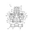
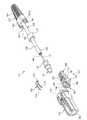
図1に示すように、本発明の第1実施形態に係る光コネクタ11は、ハウジング13と、フェルール15と、フェルール保持部材17と、ばね部材19と、加締めリング(加締め部材)21と、ブーツ23と、を主要な構成部材とし、不図示の相手光コネクタと結合することで光ファイバケーブル25の光ファイバ27の先端を突き合わせた状態に接続する。これにより、例えば自動車用等における光ファイバ相互を接続する。Embodiments according to the present invention will be described below with reference to the drawings.
As shown in FIG. 1, the
合成樹脂製のハウジング13は、図示しない相手光コネクタとの一対の結合開口部29を前方に有する。ハウジング13の後方には、後方開口31が形成される。ハウジング13は、結合開口部29の奥側に、フェルール保持部材17に保持された一対のフェルール15を後方開口31から挿入して収容する。なお、本明細書中において、光コネクタ11は、結合開口部29を前、後方開口31を後ろとして説明する。 The
ハウジング13の内方には保持部材収容空間30が形成され、保持部材収容空間30は後方がハウジング13の後端で上記後方開口31となって開口する(図10参照)。この保持部材収容空間30には、フェルール保持部材17の保持部材本体部33が収容される。保持部材収容空間30に保持部材本体部33が収容されたフェルール保持部材17は、加締め部35が後方開口31から突出した状態でハウジング13に装着される。 A holding
フェルール15は、光ファイバケーブル25における光ファイバ27の先端部37に接続される。即ち、それぞれのフェルール15には、光ファイバケーブル25から外被39や図示しない抗張力線が除去されて露出した光ファイバ27の先端部37が挿入固定される。より具体的には、光ファイバ27から更に内部被覆の除去された裸のファイバ芯線が接着剤等によって挿入固定され、ファイバ芯線の先端はフェルール細径部41の先端面に配置される。
フェルール15の外周面には、後述するフェルール保持部材17の支持部43に係止されて先端側への移動が規制される円環部45が突設されている。そして、フェルール15は、ハウジング13内においてフェルール保持部材17によって軸線方向に移動自在に収容され、且つフェルール保持部材17に装着されるばね部材19によってハウジング13の先端側へ弾性付勢される。The
On the outer peripheral surface of the
フェルール15は、相手光コネクタの相手フェルールと、フェルール細径部41の接合端面を以って突き合わせ接続される。これにより、フェルール15によってコネクタ接続可能に成端された光ファイバ27が相手光コネクタの光線路と接続される。 The
円環部45の後面に先端が係合するばね部材19によって前方へ弾性付勢されるフェルール15は、フェルール保持部材17の支持部43に円環部45の前面が当接することで、それ以上の前方への突出が阻止される。フェルール15は、相手光コネクタとの突き合わせ時にばね部材19の弾性変形範囲内で、接続方向後方へ若干押し込むことが可能であるから、これにより極度の応力集中による破損等が防止される。そして、ばね部材19の付勢力がフェルール同士間の突き合わせ力として作用して、目的の接続損失が安定して得られるように構成されている。 The
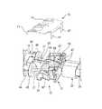
図2に示すように、フェルール保持部材17は硬質樹脂材料よりなり、光ファイバ27を内方に載置する一対のファイバ挿入溝47が形成された保持部材本体部33を有する。ファイバ挿入溝47は、前方が互いに離間されるように保持部材側面49に凹設されている。保持部材本体部33の後端には、後方に向けて加締め部35が突設されている。加締め部35の内方には、上記ファイバ挿入溝47が延在する。フェルール保持部材17は、光ファイバ27がファイバ挿入溝47に挿通された状態でハウジング13内に収容されると共に、ハウジング13の後方開口31から加締め部35が導出される。 As shown in FIG. 2, the
フェルール保持部材17は、ハウジング13内に装着されてハウジング13内におけるフェルール15及び光ファイバ27を位置決め保持する。フェルール保持部材17の保持部材先端部51には支持部43が設けられ、支持部43は円環部45を係止してフェルール15の先端側への移動を規制する。支持部43は、フェルール15の外周面に沿って延びるU字状支持部44と、一対のU字状支持部44を保持部材先端部51に連設する延出壁部(連結支持部)53とを有する。各U字状支持部44は、それぞれのフェルール15を載置して下方から支持できるように半円筒状に形成されている。 The
保持部材本体部33の保持部材側面49には、ファイバ挿入溝47を挟んで一対のばね固定部55が形成される。このばね固定部55には、後述するばね部材19の係合片部57(図6参照)が嵌入される。 A pair of
フェルール保持部材17の保持部材後端部59には光ファイバ27が導出される加締め部35が設けられ、加締め部35は光ファイバケーブル25の抗張力線及び外被39の少なくとも一方を加締めリング21によってその外周面61に装着する。加締め部35の外周面61には、外被39等の加締め強度を向上させるための環状突起63が軸線方向に複数形成されている。上記ファイバ挿入溝47は、この環状突起63を切断して切り込み形成される。これにより、光ファイバ27は、ファイバ軸線直交方向にファイバ挿入溝47へ挿入が可能となる。即ち、閉じられた筒体の場合のように光ファイバ27を内方に先通しする必要がない。 The holding member
保持部材本体部33の両側の外側部65には、弾性係止片67が設けられる。弾性係止片67は、先端側が保持部材本体部33に接続し、後端側が徐々に離間した自由端となっている。即ち、平面視で逆ハ字状に開脚している(図2参照)。この自由端の先端は、係止爪69として形成される。弾性係止片67は、係止爪69が外側部65に接近離反する方向に弾性変形可能となっている。後述するように、この係止爪69は、ハウジング13の内方に設けた係止段部32に係止される(図10参照)。
図1及び図6に示すように、ばね部材19は、ばね性の高い金属材料や樹脂材料等の薄板からなる。ばね部材19は二対の平行な弾性アーム片71を有し、それぞれの間に光ファイバ27を配置して、その先端でフェルール15を前方へ押圧する。ばね部材19は弾性アーム片71と反対側に下方へ垂直に曲げられる一対の係合片部57が形成され、係合片部57は保持部材本体部33に形成されるばね固定部55に係合する。ばね部材19は、係合片部57をばね固定部55に係合することで、フェルール保持部材17からの離脱が防止され、ファイバ挿入溝47を覆った状態でフェルール保持部材17に装着される(図7,8参照)。 As shown in FIGS. 1 and 6, the
加締めリング21は、本第1実施形態において、2芯の光ファイバ27を挿通可能とする楕円筒状に形成される。加締めリング21には塑性変形しやすい金属材料が好適に用いられる。加締めリング21は、加締め部35の外周面61に沿わされた外被39等の外側に被せられ、塑性変形により縮径されることで外被39等を加締め部35に固定する。 In the first embodiment, the
ハウジング13の保持部材収容空間30には、後方開口31よりも側壁内面73を外側に削った不図示の凹状部が形成される。凹状部と側壁内面73との間には係止段部32が形成され、この係止段部32には前方より上記弾性係止片67の係止爪69が当接して係止される(図10参照)。 In the holding
即ち、フェルール保持部材17は、加締め部35を後方にしてハウジング13の後方開口31から挿入される。後方開口31に挿入されたフェルール保持部材17は、両側一対の弾性係止片67が側壁内面73によって相互に接近する方向に撓ませられる。弾性係止片67が撓んだフェルール保持部材17は、更に保持部材収容空間30へ挿入されると、弾性係止片67の係止爪69が凹状部に達する。凹状部に達した一対の係止爪69は、弾性係止片67が弾性復元力によって開くことで、係止段部32に係止されて、フェルール保持部材17のハウジング13からの後方抜けを阻止する。 That is, the
光ファイバケーブル25は、光ファイバ27がフェルール保持部材17の加締め部35から導出される一方、加締め部35の外周に外被39が被せられる。加締め部35に被せられた外被39は、その外側から楕円筒状の加締めリング21が加締め付けられることで、加締め部35に固定される。これにより、光ファイバケーブル25とフェルール保持部材17とは一体的に固定される。光ファイバケーブル25が後方に引っ張られると、係止爪69が係止段部32に当接してフェルール保持部材17の抜けが規制されるように構成されている。即ち、これら後方開口31、凹状部、係止段部32、弾性係止片67、及び係止爪69は、フェルール保持部材17がハウジング13の後方開口31から挿入し且つハウジング内からの抜脱を阻止する係止機構75(図10参照)を構成する。 In the
このフェルール保持部材17の外側部65における後方端には、ブーツ係止用切欠部77が形成されている。ブーツ係止用切欠部77は、保持部材本体部33の後方端のそれぞれの外側部65から外側に向かって垂直に突出する一対の切欠形成片79の間に形成される。従って、ブーツ係止用切欠部77は、切欠形成片同士の先端間隙が開口端81となって開放する。ブーツ係止用切欠部77は、フェルール保持部材17がハウジング13の保持部材収容空間30に挿入されることで、開口端81がハウジング13の側壁内面73により閉塞される。つまり、開放されていたブーツ係止用切欠部77は、側壁内面73によって開口端81が閉じた穴状となる。このブーツ係止用切欠部77は、ブーツ23の抜けを阻止するための部位となる。 A
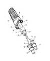
図1及び図10に示すように、ブーツ23は、合成ゴム等の軟質材からなり、光ファイバケーブル25及び金属製の加締めリング21の外周を覆う保護部83を有する。保護部83の基端側には加締め部収容穴85が形成され、加締め部収容穴85は光ファイバケーブル25の外被39を加締め部35に加締め固定した加締めリング21を外周側から覆う。保護部83の周囲には、保護部83に適宜な屈曲性を付与する複数の周溝87が形成される。ブーツ23は、保護部83に連設されてハウジング13の後方開口31を覆う矩形状のフランジ部89を有する。 As shown in FIGS. 1 and 10, the
フランジ部89の両側には、前方(ハウジング内方側)に向かってT字状突起91が突設されている。上述したブーツ係止用切欠部77と、このT字状突起91とは、加締め部35を挟んで左右一対設けられる。T字状突起91は、フランジ部89から垂直に突出する首部93の先端が膨出部となる。本第1実施形態では、膨出部は、首部93に直交する方向の柱状に形成される。この他、膨出部は、底辺側が首部93に接続される三角板状、直径側が首部93に接続される半円板状等に形成されてもよい。 On both sides of the
T字状突起91は、フランジ部89と一体に成形されて可撓性を有している。この可撓性により、T字状突起91は膨出部が外側に変位するように開脚自在となる。そこで、T字状突起91は、首部93がブーツ係止用切欠部77の開口端81から挿入可能となる。首部93がブーツ係止用切欠部77に挿入されたT字状突起91は、膨出部が切欠形成片79に当たって後方への抜けが阻止される。T字状突起91は、フェルール保持部材17がハウジング13に装着されていない状態では、首部93が開口端81から離脱可能となる。一方、フェルール保持部材17がハウジング13に装着されると、開口端81が側壁内面73によって閉鎖されるので、首部93は開口端81から抜けなくなる。これにより、T字状突起91がブーツ係止用切欠部77から確実に抜けなくなり、これらハウジング13、フェルール保持部材17、ブーツ23が一体に固定されて組み付けられる。 The T-shaped
次に、図3〜図8を参照しながら上記構成を有する光コネクタ11の組立方法を説明する。
光コネクタ11を組み立てるには、先ず、図3に示すように、光ファイバケーブル25のケーブル先端部95にブーツ23と加締めリング21を順次通す。そして、ケーブル先端部95の外被39を除去して露出した光ファイバ27の先端部37にフェルール15を固定する。
次に、図4に示すように、フェルール保持部材17に凹設されたファイバ挿入溝47に光ファイバ27を入れながらフェルール15をフェルール保持部材17の支持部43に載せる。この際、支持部43は、一対のU字状支持部44が各フェルール15を外周面に沿って保持すると共に円環部45を係止してフェルール15の先端側への移動を規制することができるので、フェルール15を支持部43に保持させる固定作業が容易となる。Next, an assembling method of the
To assemble the
Next, as shown in FIG. 4, the
図5及び図6に示すように、ファイバ挿入溝47を覆って、フェルール保持部材17に装着したばね部材19の先端を円環部45の後面に係合させることよりフェルール15を軸線方向前方へ付勢する(図7参照)。そして、光ファイバ27の導出された保持部材後端部59の加締め部35に、ケーブル先端部95の外被39を被せた後、その外周を加締めリング21にて加締め固定する。
図7に示すように、フェルール15を保持したフェルール保持部材17をハウジング13の後方開口31から挿入してブーツ23と共にハウジング13に組み付ける。As shown in FIGS. 5 and 6, the
As shown in FIG. 7, the
なお、本第1実施形態では、2芯の光ファイバ27が外被39に覆われる。外被39は、一対の平行なチューブ状外被が接続されたものとなる。この外被39を筒状の加締め部35の外周面61(図2参照)に被せるには、先ず、チューブ連結部97(図4参照)を分離する。そして、それぞれのチューブ状外被のチューブ連結部97を軸線に沿う方向に切り裂く。これにより、それぞれのチューブ状外被は、半円筒状に開くことが可能となる。それぞれ半円筒状に開かれたチューブ状外被は、筒状となった加締め部35の左右の片側に被せられ、その外側が加締めリング21によって一括に固定される。 In the first embodiment, the two-core
ブーツ23は、T字状突起91の首部93が、フェルール保持部材17のブーツ係止用切欠部77に外側(首部93の軸線に直交する方向)から撓ませながら挿入される。これにより、図8に示すように、T字状突起91の膨出部がブーツ係止用切欠部77を挟む一対の切欠形成片79に当たり、光ファイバケーブル25の導出方向への抜けが阻止される。この際、ハウジング内に収容されていないフェルール保持部材17のブーツ係止用切欠部77には、開口端81よりT字状突起91の首部93(図7参照)を弾性変形させて容易に挿入できる。つまり、ブーツ23とフェルール保持部材17との仮組み付けが容易に行える。 The
一方、ハウジング13、フェルール保持部材17、ブーツ23を一体にする本組付けでは、T字状突起91をブーツ係止用切欠部77に係止したフェルール保持部材17が、ハウジング13の後方開口31から挿入される(図8参照)。T字状突起91の首部93が挿入されたブーツ係止用切欠部77は、図9及び図10に示すように、ハウジング13内に収容されると、開口端81(図7参照)がハウジング13の側壁内面73により閉塞される。これにより、T字状突起91は、ブーツ係止用切欠部77から抜けが確実に阻止されることになる。 On the other hand, in the present assembly in which the
本第1実施形態では、外被39が剥かれて露出した光ファイバ27の先端部37側から順に、ブーツ23、加締めリング21が光ファイバケーブル25に通され、その後、光ファイバ27にフェルール15が接続される。外被39が加締めリング21によって加締め部35に固定された後、加締めリング21がブーツ23の保護部83によって覆われる。加締めリング21を覆ったブーツ23は、ハウジング内方側のフランジ部89から前方に突出するT字状突起91が、フェルール保持部材17に係止される。そして最後に、ブーツ23を係止したフェルール保持部材17が、ハウジング13の後方開口31から装着される。即ち、フェルール保持部材17にブーツ23を組み付ける仮組み付けと、フェルール保持部材17とハウジング13を組み付ける本組付けの全てが、光ファイバケーブル25の軸線に沿う同一組立方向となり、組立が容易となる。即ち、組立自動化への対応も容易となる。 In the first embodiment, the
次に、本第1実施形態に係る光コネクタ11の組立方法の作用を説明する。
上述した組立方法では、光ファイバ27に先通しする部材が、ブーツ23と加締めリング21の2部材のみとなる。光ファイバ27の先端部37にフェルール15が固定された光ファイバ27は、ファイバ軸線直交方向からフェルール保持部材17のファイバ挿入溝47に挿入配置される。図7及び図8に示したように、フェルール保持部材17にばね部材19が取り付けられることで、ファイバ挿入溝47が閉鎖されて、閉塞されたファイバ挿入溝47に保持される光ファイバ27フェルール15が脱落しなくなる。フェルール15は、更に支持部43とばね部材19とによって軸線に沿う方向に付勢された状態で円環部45が挟まれることで、保持が確実となる。これにより、光ファイバケーブル25が複数の光ファイバ27を備える場合であっても、それぞれの光ファイバ27に固定されるフェルール15がそれぞればね部材19に付勢されながら支持部43に保持されて、フェルール保持部材17に組み込まれる。即ち、ばね部材19により付勢状態にある複数のフェルール15を同時にハウジング13に挿入することが容易となる。Next, the operation of the assembling method of the
In the assembly method described above, there are only two members, the
次に、上記構成を有する光コネクタ11の作用を説明する。
本第1実施形態に係る光コネクタ11では、ファイバ端末加工時、ばね部材19やフェルール保持部材17を光ファイバ27に先通しする必要がなくなるため、端末加工性が向上する。また、光ファイバ27が収容されたファイバ挿入溝47を覆うようにばね部材19が固定されるため、ハウジング挿入時の光ファイバ27の脱落を防止できる。更に、フェルール保持部材17は、支持部43とばね部材19とでフェルール15の円環部45を挟み、且つこのばね部材19によって支持部43のU字状支持部44に弾性接触させた状態でフェルール15が保持されるため、ハウジング挿入作業が容易となる。Next, the operation of the
In the
また、ブーツ係止用切欠部77にT字状突起91の首部93を挿入したフェルール保持部材17がハウジング内に収容されると、ブーツ係止用切欠部77の開口端81がハウジング13の側壁内面73により閉塞される。これにより、ブーツ23は、T字状突起91を介してフェルール保持部材17に係止され、ハウジング13から抜けなくなる。 Further, when the
更に、フェルール15を保持したフェルール保持部材17が、フェルール15ごとハウジング13の後方開口31から挿入されると、ハウジング13とフェルール保持部材17とに亘って設けられた係止機構75によってフェルール保持部材17の後抜けが規制され、光コネクタ11の組み立てが容易となる。また、この際、フェルール保持部材17のブーツ係止用切欠部77に挿入したT字状突起91の首部93も、上述したように開口端81が側壁内面73によって塞がれて脱落が規制されるので、同時にブーツ23の組み付けも完了し、組み立てが効率的に行える。 Further, when the
次に、図11〜図13に示す本発明の第2実施形態に係る光コネクタ111を説明する。
図11に示すように、本第2実施形態に係る光コネクタ111は、上記第1実施形態の光コネクタ11と同様に、ハウジング113と、フェルール15と、フェルール保持部材117と、ばね部材119と、加締めリング21と、ブーツ123と、を主要な構成部材としている。
但し、上記第1実施形態の光コネクタ11が、2芯の光ファイバ27を外被39で覆った光ファイバケーブル25のケーブル先端部95に取付けられる光コネクタであったのに対し、本第2実施形態に係る光コネクタ111は、1芯の光ファイバ27及び抗張力線140を外被139で覆った光ファイバケーブル125のケーブル先端部195に取付けられる光コネクタである点が異なる。そこで、ハウジング113、フェルール保持部材117、ばね部材119及びブーツ123の形状が異なるが、他の構成は上記第1実施形態の光コネクタ11と同じである。Next, an
As shown in FIG. 11, the
However, the
合成樹脂製のハウジング113は、図示しない相手光コネクタとの一つの結合開口部129を前方に有する。ハウジング113の後方には、後方開口31が形成される。ハウジング113は、結合開口部129の奥側に、フェルール保持部材117に保持された一本のフェルール15を後方開口31から挿入して収容する。 The
ハウジング113の内方には保持部材収容空間が形成され、この保持部材収容空間には、フェルール保持部材117の保持部材本体部133が収容される。保持部材収容空間に保持部材本体部133が収容されたフェルール保持部材117は、加締め部135が後方開口31から突出した状態でハウジング113に装着される。 A holding member housing space is formed inside the
図12(a)に示すように、フェルール保持部材117は硬質樹脂材料よりなり、光ファイバ27を内方に載置する一本のファイバ挿入溝147が形成された保持部材本体部133を有する。ファイバ挿入溝147は、保持部材側面149の前後方向に沿って凹設されている。保持部材本体部133の後端には、後方に向けて加締め部135が突設されている。加締め部135の内方には、上記ファイバ挿入溝147が延在する。フェルール保持部材117は、光ファイバ27がファイバ挿入溝147に挿通された状態でハウジング113内に収容されると共に、ハウジング113の後方開口31から加締め部135が導出される。 As shown in FIG. 12A, the
フェルール保持部材117は、ハウジング113内に装着されてハウジング113内におけるフェルール15及び光ファイバ27を位置決め保持する。フェルール保持部材117の保持部材先端部151には支持部143が設けられ、支持部143は円環部45を係止してフェルール15の先端側への移動を規制する。支持部143は、フェルール15の外周面に沿って延びるU字状支持部144と、U字状支持部144の両端を保持部材先端部151に連設する一対の連結支持部153とを有する。U字状支持部144は、フェルール15を載置して下方から支持できるように半円筒状に形成されている。 The
保持部材本体部133の保持部材側面149には、ファイバ挿入溝147を挟んで一対のばね固定部155が形成される。このばね固定部155には、後述するばね部材119の係合片部157(図11参照)が嵌入される。 A pair of
フェルール保持部材117の保持部材後端部159には光ファイバ27が導出される加締め部135が設けられ、加締め部135は光ファイバケーブル125の抗張力線140及び外被139の少なくとも一方を加締めリング21によってその外周面161に装着する。加締め部135の外周面161には、外被139等の加締め強度を向上させるための環状突起163が軸線方向に複数形成されている。上記ファイバ挿入溝147は、この環状突起163を切断して切り込み形成される。これにより、光ファイバ27は、ファイバ軸線直交方向にファイバ挿入溝147へ挿入が可能となる。即ち、閉じられた筒体の場合のように光ファイバ27を内方に先通しする必要がない。 The holding member
保持部材本体部133の両側の外側部165には、弾性係止片167及びブーツ係止用突起177が設けられる。弾性係止片167は、先端側が保持部材本体部133に接続し、後端側が徐々に離間した自由端となっている。即ち、平面視で逆ハ字状に開脚している(図12(b)参照)。この自由端の先端は、係止爪169として形成される。弾性係止片167は、係止爪169が外側部165に接近離反する方向に弾性変形可能となっている。この係止爪169は、ハウジング113の内方に設けた係止段部(図示せず)に係止される。ブーツ係止用突起177は、保持部材本体部133の後方端のそれぞれの外側部165から外側に向かって垂直に突出している。 Elastic locking
図11に示すように、ばね部材119は、ばね性の高い金属材料や樹脂材料等の薄板からなる。ばね部材119は一対の平行な弾性アーム片171を有し、間に光ファイバ27を配置して、その先端でフェルール15の円環部45を前方へ押圧する。ばね部材119は弾性アーム片171と反対側に下方へ垂直に曲げられる一対の係合片部157が形成され、係合片部157は保持部材本体部133に形成されるばね固定部155に係合する(図12(b)参照)。ばね部材119は、係合片部157をばね固定部155に係合することで、フェルール保持部材117からの離脱が防止され、ファイバ挿入溝147を覆った状態でフェルール保持部材117に装着される(図13(a)参照)。 As shown in FIG. 11, the
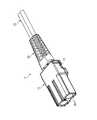
図11及び図13に示すように、ブーツ123は、合成ゴム等の軟質材からなり、光ファイバケーブル125及び金属製の加締めリング21の外周を覆う保護部183を有する。保護部183の基端側には加締め部収容穴185が形成され、加締め部収容穴185は光ファイバケーブル125の外被139を加締め部135に加締め固定した加締めリング21を外周側から覆う。保護部183の周囲には、保護部183に適宜な屈曲性を付与する複数の周溝187が形成される。 As shown in FIGS. 11 and 13, the
保護部183の基端両側には、前方(ハウジング内方側)に向かって一対の掛止突起191が突設されている。掛止突起191は可撓性を有しており、この可撓性により先端が外側に変位するように開脚自在となる。そこで、図13(a)に示すように、掛止突起191の開口部191aにブーツ係止用突起177を挿入することで、ブーツ123はフェルール保持部材117からの抜けが阻止される。
そして最後に、図13(b)に示すように、ブーツ123を係止したフェルール保持部材117が、ハウジング113の後方開口131から装着され、光コネクタ111の組立が完了する。A pair of latching
Finally, as shown in FIG. 13B, the
即ち、本第2実施形態に係る光コネクタ111によれば、上記第1実施形態に係る光コネクタ11と同様に、ファイバ端末加工時、ばね部材119やフェルール保持部材117を光ファイバ27に先通しする必要がなくなるため、端末加工性が向上する。また、光ファイバ27が収容されたファイバ挿入溝147を覆うようにばね部材119が固定されるため、ハウジング挿入時の光ファイバ27の脱落を防止できる。更に、フェルール保持部材117は、支持部143とばね部材119とでフェルール15の円環部45を挟み、且つこのばね部材119によって支持部143のU字状支持部144に弾性接触させた状態でフェルール15が保持されるため、ハウジング挿入作業が容易となる。 That is, according to the
従って、上記第1及び第2実施形態に係る光コネクタ11,111及びその組立方法によれば、加工作業性、組立性の向上によりコストを低減できる。
なお、本発明の光コネクタ及び光コネクタの組立方法は、上述した各実施形態に限定されるものではなく、適宜、変形、改良等が可能である。その他、上述した実施形態における各構成要素の材質、形状、寸法、数、配置箇所等は本発明を達成できるものであれば任意であり、限定されない。
例えば、上記各実施形態おいては、フェルール保持部材17(117)の加締め部35(135)の外周面61(161)に被せられた光ファイバケーブル25(125)の外被39(139)を固定する加締め部材として、楕円筒状の加締めリング21を用いたが、本発明はこれに限定するものではなく、略楕円筒状の加締めプレートを用いることもできる。矩形の金属板を折り曲げ形成して略楕円筒状に形成された加締めプレートは、光ファイバケーブル25(125)の軸線に沿うスリットを備え、光ファイバケーブル25(125)の外被39(139)を加締め部35に加締め固定する。Therefore, according to the
The optical connector and the optical connector assembling method of the present invention are not limited to the above-described embodiments, and can be appropriately modified and improved. In addition, the material, shape, dimensions, number, arrangement location, and the like of each component in the above-described embodiment are arbitrary and are not limited as long as the present invention can be achieved.
For example, in each of the above-described embodiments, the jacket 39 (139) of the optical fiber cable 25 (125) that covers the outer peripheral surface 61 (161) of the caulking portion 35 (135) of the ferrule holding member 17 (117). As the caulking member for fixing the oval tube, the oval
11…光コネクタ
13…ハウジング
15…フェルール
17…フェルール保持部材
19…ばね部材
21…加締めリング(加締め部材)
23…ブーツ
25…光ファイバケーブル
27…光ファイバ
31…後方開口
35…加締め部
37…先端部
39…外被
43…支持部
44…U字状支持部
45…円環部
47…ファイバ挿入溝
49…保持部材側面
51…保持部材先端部
53…延出壁部(連結支持部)
55…ばね固定部
59…保持部材後端部
61…外周面
65…外側部
73…側壁内面
75…係止機構
77…ブーツ係止用切欠部
81…開口端
83…保護部
89…フランジ部
91…T字状突起
93…首部
95…ケーブル先端部DESCRIPTION OF
DESCRIPTION OF
55 ...
Claims (4)
Translated fromJapanese前記フェルール保持部材は、
前記フェルールの先端側への移動を規制するため前記フェルール保持部材の先端部に設けられた支持部と、
前記光ファイバを収容するため前記フェルール保持部材の側面に凹設されたファイバ挿入溝と、
前記光ファイバケーブルの抗張力線及び外被の少なくとも一方を固定する加締め部材をその外周面に装着するため前記光ファイバが導出される前記フェルール保持部材の後端部に設けられた加締め部と、
前記フェルールを前記支持部に弾性接触させると共に前記ファイバ挿入溝を覆った状態で装着される前記ばね部材を固定するため前記フェルール保持部材の側面に設けられたばね固定部と、を備え、
前記ばね部材は、薄板からなると共に、前記ファイバ挿入溝に収容された前記光ファイバを前記ファイバ挿入溝と前記ばね部材とで挟んで脱落不能とするように、ファイバ軸線直交方向から前記フェルール保持部材の側面に装着されて前記ばね固定部に固定されており、
前記フェルールを保持した前記フェルール保持部材は、前記ハウジングの後方に形成された後方開口から挿入されて前記ハウジング内に装着されていることを特徴とする光コネクタ。A ferrule connected to a cable tip of an optical fiber cable; a housing that accommodates the ferrule; a ferrule holding member that is mounted in the housing and positions and holds the ferrule and the optical fiber in the housing; and the ferrule. An optical connector comprising a spring member biased toward the distal end side of the housing,
The ferrule holding member is
A support provided atthe tip of the ferrule holding member to restrict movement of the ferrule towardthe tip ;
A fiber insertion groove recessed ina side surface of theferrule holding member to accommodate the optical fiber;
A caulkingportion provided at arear end portion of the ferrule holding member from which the optical fiber is led out in order to attach a caulking member for fixing at least one of a tensile strength line and a jacket of the optical fiber cable to an outer peripheral surface thereof; ,
A spring fixing portionprovided on a side surface of the ferrule holding member for fixing the spring member mounted in a state of covering the fiber insertion groove while elastically contacting the ferrule with the support portion;
The spring member is formed of a thin plate, and the ferrule holding member from the direction perpendicular to the fiber axis is set so that the optical fiber accommodated in the fiber insertion groove cannot be dropped by being sandwiched between the fiber insertion groove and the spring member. Is fixed to the spring fixing part.
The optical connector, wherein the ferrule holding member holding the ferrule is inserted from a rear opening formed at the rear of the housing and is mounted in the housing .
前記フェルールの外周面には、前記U字状支持部に係止されて先端側への移動が規制される円環部が突設されていることを特徴とする請求項1に記載の光コネクタ。The support portion includes a U-shaped support portion extending along the outer peripheral surface of the ferrule, and a connection support portion that continuously connects the U-shaped support portion to the distal end portion of the holding member,
The optical connector according to claim 1, wherein an annular portion that protrudes from the outer peripheral surface of the ferrule and that is locked to the U-shaped support portion and is restricted from moving toward the distal end is provided. .
前記フランジ部のハウジング内方側に突設されたT字状突起の首部が、前記フェルール
保持部材の外側部に形成されて前記ハウジングの側壁内面により開口端が閉塞されるブーツ係止用切欠部に挿入されることを特徴とする請求項1又は2に記載の光コネクタ。A boot having a protective portion that covers the outer periphery of the optical fiber cable and the caulking member, and a flange portion that is connected to the protective portion and covers a rear opening of the housing;
A notch portion for boot locking, in which a neck portion of a T-shaped projection protruding from the inside of the housing of the flange portion is formed on the outer side of the ferrule holding member and the open end is closed by the inner surface of the side wall of the housing The optical connector according to claim 1, wherein the optical connector is inserted into the optical connector.
前記ケーブル先端部の外被を除去して露出した光ファイバの先端部にフェルールを固定する工程と、
フェルール保持部材の側面に凹設されたファイバ挿入溝に前記光ファイバを入れながら前記フェルールを前記フェルール保持部材の先端部に設けられた支持部に載せる工程と、
前記ファイバ挿入溝に収容された前記光ファイバを前記ファイバ挿入溝とばね部材とで挟んで脱落不能とするように、薄板からなる前記ばね部材をファイバ軸線直交方向から前記フェルール保持部材の側面に装着して固定し、前記固定したばね部材により前記フェルールを軸線方向前方へ付勢する工程と、
前記光ファイバが導出された前記フェルール保持部材の後端部に設けられた加締め部に、前記ケーブル先端部の抗張力線及び外被の少なくとも一方を前記加締め部材にて固定する工程と、
前記フェルールを保持した前記フェルール保持部材を、ハウジングの後方に形成された後方開口から挿入して前記ハウジングに組み付ける工程と、を含むことを特徴とする光コネクタの組立方法。Passing the caulking member through the end of the optical fiber cable;
Fixing the ferrule to the exposed optical fiber tip by removing the outer sheath of the cable tip; and
Placing the ferruleon a supportprovided at thetip of the ferrule holding member while inserting the optical fiber into a fiber insertion groove recessed ina side surface of the ferrule holding member;
The spring member made of a thin plate is attached to the side surface of the ferrule holding member from the direction perpendicular to the fiber axis so that the optical fiber housed in the fiber insertion groove cannot be dropped by being sandwiched between the fiber insertion groove and the spring member. And urging the ferrule forward in the axial direction by thefixed spring member;
Fixing at least one of a tensile strength line and a jacket of the cable tip to the caulking portion provided atthe rear end of the ferrule holding member from which the optical fiber is led, and thecaulking member ;
Inserting the ferrule holding member holding the ferrulefrom a rear opening formed at the rear of thehousing and assembling the ferrule holding member to the housing.
Priority Applications (4)
| Application Number | Priority Date | Filing Date | Title |
|---|---|---|---|
| JP2012277095AJP6122291B2 (en) | 2012-08-10 | 2012-12-19 | Optical connector and optical connector assembling method |
| US13/958,734US9033591B2 (en) | 2012-08-10 | 2013-08-05 | Optical connector and method of assembling the optical connector |
| DE102013215678.2ADE102013215678B4 (en) | 2012-08-10 | 2013-08-08 | Optical connector and method for mounting the optical connector |
| CN201310349603.8ACN103576251B (en) | 2012-08-10 | 2013-08-12 | Optical connector and method of assembling same |
Applications Claiming Priority (3)
| Application Number | Priority Date | Filing Date | Title |
|---|---|---|---|
| JP2012178654 | 2012-08-10 | ||
| JP2012178654 | 2012-08-10 | ||
| JP2012277095AJP6122291B2 (en) | 2012-08-10 | 2012-12-19 | Optical connector and optical connector assembling method |
Publications (2)
| Publication Number | Publication Date |
|---|---|
| JP2014056229A JP2014056229A (en) | 2014-03-27 |
| JP6122291B2true JP6122291B2 (en) | 2017-04-26 |
Family
ID=50048403
Family Applications (1)
| Application Number | Title | Priority Date | Filing Date |
|---|---|---|---|
| JP2012277095AActiveJP6122291B2 (en) | 2012-08-10 | 2012-12-19 | Optical connector and optical connector assembling method |
Country Status (4)
| Country | Link |
|---|---|
| US (1) | US9033591B2 (en) |
| JP (1) | JP6122291B2 (en) |
| CN (1) | CN103576251B (en) |
| DE (1) | DE102013215678B4 (en) |
Families Citing this family (31)
| Publication number | Priority date | Publication date | Assignee | Title |
|---|---|---|---|---|
| JP2012220731A (en)* | 2011-04-08 | 2012-11-12 | Yazaki Corp | Optical connector |
| JP5882765B2 (en)* | 2012-02-02 | 2016-03-09 | 矢崎総業株式会社 | Optical connector |
| JP6122291B2 (en)* | 2012-08-10 | 2017-04-26 | 矢崎総業株式会社 | Optical connector and optical connector assembling method |
| JP6085471B2 (en) | 2012-12-21 | 2017-02-22 | 矢崎総業株式会社 | Optical connector |
| JP6272649B2 (en) | 2013-02-15 | 2018-01-31 | 矢崎総業株式会社 | Optical connector |
| JP6425003B2 (en)* | 2014-01-17 | 2018-11-21 | 矢崎総業株式会社 | Optical connector and mating structure of optical connector |
| US10209459B2 (en) | 2014-09-26 | 2019-02-19 | Commscope Telecommunications (Shanghai) Co., Ltd. | Optical fiber connector and assembly method therefor |
| EP3203586B1 (en)* | 2016-02-02 | 2020-07-22 | Yazaki Europe Ltd | Electrical connector |
| JP6307539B2 (en)* | 2016-02-26 | 2018-04-04 | 株式会社フジクラ | Optical connector with optical fiber and manufacturing method thereof |
| CN107666051B (en)* | 2016-07-29 | 2020-06-16 | 伟电科技股份有限公司 | Multi-core SC connector and socket |
| CN206788418U (en)* | 2017-06-08 | 2017-12-22 | 新科实业有限公司 | Optical module package |
| CN111051945B (en) | 2017-06-28 | 2023-12-29 | 康宁研究与开发公司 | Compact fiber optic connector, cable assembly and method of making the same |
| USD1002540S1 (en) | 2017-11-30 | 2023-10-24 | Corning Research & Development Corporation | Connector for making optical connections |
| CN112534326B (en)* | 2018-07-11 | 2022-10-11 | 扇港元器件股份有限公司 | Ultra small form factor socket for fiber optic connector |
| USD949107S1 (en) | 2019-12-20 | 2022-04-19 | Corning Research & Development Corporation | Dustplug for a multiport optical connection device |
| US11604320B2 (en) | 2020-09-30 | 2023-03-14 | Corning Research & Development Corporation | Connector assemblies for telecommunication enclosures |
| AU2021368055A1 (en) | 2020-10-30 | 2023-06-08 | Corning Research & Development Corporation | Female fiber optic connectors having a rocker latch arm and methods of making the same |
| US11880076B2 (en) | 2020-11-30 | 2024-01-23 | Corning Research & Development Corporation | Fiber optic adapter assemblies including a conversion housing and a release housing |
| US11927810B2 (en) | 2020-11-30 | 2024-03-12 | Corning Research & Development Corporation | Fiber optic adapter assemblies including a conversion housing and a release member |
| US11994722B2 (en) | 2020-11-30 | 2024-05-28 | Corning Research & Development Corporation | Fiber optic adapter assemblies including an adapter housing and a locking housing |
| CN113325536B (en)* | 2021-06-23 | 2023-01-17 | 重庆迎世科技有限公司 | High flame-retardant communication optical cable for rail transit |
| USD1060249S1 (en) | 2021-08-30 | 2025-02-04 | Corning Research & Development Corporation | Multifiber connector for making optical connections |
| USD1070775S1 (en)* | 2022-10-28 | 2025-04-15 | Molex, Llc | Connector |
| USD1047918S1 (en)* | 2022-10-28 | 2024-10-22 | Molex, Llc | Connector |
| USD1047919S1 (en)* | 2022-10-28 | 2024-10-22 | Molex, Llc | Connector |
| USD1070776S1 (en)* | 2022-10-28 | 2025-04-15 | Molex, Llc | Connector |
| USD1065090S1 (en)* | 2022-10-31 | 2025-03-04 | Cps Technology Holdings Llc | Male charging port connector |
| US12386124B2 (en)* | 2022-11-30 | 2025-08-12 | Mellanox Technologies, Ltd. | Device for holding a plurality of ferrules against a respective plurality of receptacles |
| USD986832S1 (en)* | 2023-02-27 | 2023-05-23 | Shenzhen Lisite Trading Co., Ltd. | HDMI splitter |
| USD1089104S1 (en) | 2023-11-17 | 2025-08-19 | Molex, Llc | Connector |
| USD1089105S1 (en) | 2023-11-17 | 2025-08-19 | Molex, Llc | Connector |
Family Cites Families (23)
| Publication number | Priority date | Publication date | Assignee | Title |
|---|---|---|---|---|
| JPH087367Y2 (en)* | 1990-06-26 | 1996-03-04 | 古河電気工業株式会社 | Optical connector |
| US5074021A (en) | 1990-10-19 | 1991-12-24 | Molex Incorporated | Tool to facilitate loading an optical fiber in a connector component |
| US6007256A (en) | 1996-09-24 | 1999-12-28 | Sumitomo Wiring Systems, Ltd. | Optical connector that reduces the number of components used, that facilitates assembly, and that prevents spontaneous disassembly, and structure for attaching a boot to an optical connector |
| JP3306410B2 (en)* | 1999-06-01 | 2002-07-24 | 日本電信電話株式会社 | Optical connector plug, method of manufacturing the same, and assembly tool |
| JP3756703B2 (en) | 1999-08-05 | 2006-03-15 | 矢崎総業株式会社 | Optical connector |
| US6511230B1 (en)* | 2000-02-04 | 2003-01-28 | Panduit Corp. | Fiber optic connection system |
| US6758601B2 (en)* | 2001-09-28 | 2004-07-06 | Adc Telecommunications, In. | Fiberoptic connector and methods |
| US7220061B2 (en) | 2002-06-24 | 2007-05-22 | Diamond Sa | Connector-plug part for an optical plug-in connection, method for connecting a connector-plug part to the end of an optical waveguide cable and device for carrying out said method |
| AU2003240129A1 (en) | 2002-07-16 | 2004-02-02 | Tyco Electronics Raychem Nv | Optical fibre connector |
| US7540667B2 (en)* | 2007-08-01 | 2009-06-02 | Ortronics, Inc. | Positional differentiating connector assembly |
| JP4482591B2 (en)* | 2008-03-28 | 2010-06-16 | ホシデン株式会社 | Optical connector |
| US7712970B1 (en)* | 2009-01-12 | 2010-05-11 | Alliance Fiber Optic Products Co., Ltd. | Detachable fiber optic connector |
| JP2011027876A (en) | 2009-07-23 | 2011-02-10 | Sanwa Denki Kogyo Co Ltd | Multiple-connection optical connector |
| TWI454770B (en)* | 2010-03-01 | 2014-10-01 | Hon Hai Prec Ind Co Ltd | Optical fiber fixing deivce and method for assembling optical fiber |
| JP2011203682A (en)* | 2010-03-26 | 2011-10-13 | Yazaki Corp | Optical connector |
| JP5599237B2 (en)* | 2010-06-23 | 2014-10-01 | 矢崎総業株式会社 | Optical connector |
| US8410909B2 (en)* | 2010-07-09 | 2013-04-02 | Corning Incorporated | Cables and connector assemblies employing a furcation tube(s) for radio-frequency identification (RFID)-equipped connectors, and related systems and methods |
| JP5400744B2 (en) | 2010-10-19 | 2014-01-29 | 古河電気工業株式会社 | Optical fiber terminal, optical fiber cable with terminal, optical connector, optical fiber cable with connector |
| US8662760B2 (en)* | 2010-10-29 | 2014-03-04 | Corning Cable Systems Llc | Fiber optic connector employing optical fiber guide member |
| JP5771075B2 (en)* | 2010-12-28 | 2015-08-26 | 矢崎総業株式会社 | Optical connector |
| JP5779905B2 (en) | 2011-02-25 | 2015-09-16 | 株式会社リコー | Image processing apparatus, image processing system, and image processing program |
| JP2012220731A (en)* | 2011-04-08 | 2012-11-12 | Yazaki Corp | Optical connector |
| JP6122291B2 (en) | 2012-08-10 | 2017-04-26 | 矢崎総業株式会社 | Optical connector and optical connector assembling method |
- 2012
- 2012-12-19JPJP2012277095Apatent/JP6122291B2/enactiveActive
- 2013
- 2013-08-05USUS13/958,734patent/US9033591B2/enactiveActive
- 2013-08-08DEDE102013215678.2Apatent/DE102013215678B4/enactiveActive
- 2013-08-12CNCN201310349603.8Apatent/CN103576251B/ennot_activeExpired - Fee Related
Also Published As
| Publication number | Publication date |
|---|---|
| DE102013215678B4 (en) | 2019-10-17 |
| CN103576251A (en) | 2014-02-12 |
| DE102013215678A1 (en) | 2014-03-06 |
| US20140044397A1 (en) | 2014-02-13 |
| JP2014056229A (en) | 2014-03-27 |
| CN103576251B (en) | 2015-07-15 |
| US9033591B2 (en) | 2015-05-19 |
Similar Documents
| Publication | Publication Date | Title |
|---|---|---|
| JP6122291B2 (en) | Optical connector and optical connector assembling method | |
| JP6272649B2 (en) | Optical connector | |
| JP5599237B2 (en) | Optical connector | |
| JP5882765B2 (en) | Optical connector | |
| JP4957363B2 (en) | Optical connector and optical connector assembling method | |
| CN100533191C (en) | Optical connector and method for assembling the optical connector | |
| JP5518979B2 (en) | Optical connector receptacle, receptacle housing, optical connector adapter, adapter housing | |
| JP6085471B2 (en) | Optical connector | |
| JPH08338924A (en) | Optical connector and method for fixing optical fiber to connector housing | |
| US11294125B2 (en) | Optical connector | |
| JP2012220731A (en) | Optical connector | |
| JP2020046582A (en) | Lc uni-boot plug connector | |
| JP2013160880A (en) | Optical connector | |
| CN115769117A (en) | Optical connector and method for manufacturing optical connector | |
| JP6267875B2 (en) | Optical connector | |
| JP6085489B2 (en) | Optical connector and optical connector assembling method | |
| KR20220145160A (en) | Plug connector | |
| JP2014178617A (en) | Optical connector | |
| JP7089485B2 (en) | Optical connector | |
| JP7144311B2 (en) | Optical connector and harness | |
| JP2007192871A (en) | Optical connector | |
| JP4033867B2 (en) | Optical connector device | |
| JP3751840B2 (en) | connector | |
| CN109891288A (en) | Optical connector plug | |
| KR20180131725A (en) | United optic connector |
Legal Events
| Date | Code | Title | Description |
|---|---|---|---|
| RD02 | Notification of acceptance of power of attorney | Free format text:JAPANESE INTERMEDIATE CODE: A7422 Effective date:20150122 | |
| A621 | Written request for application examination | Free format text:JAPANESE INTERMEDIATE CODE: A621 Effective date:20151119 | |
| A977 | Report on retrieval | Free format text:JAPANESE INTERMEDIATE CODE: A971007 Effective date:20160615 | |
| A131 | Notification of reasons for refusal | Free format text:JAPANESE INTERMEDIATE CODE: A131 Effective date:20160802 | |
| A521 | Request for written amendment filed | Free format text:JAPANESE INTERMEDIATE CODE: A523 Effective date:20160913 | |
| TRDD | Decision of grant or rejection written | ||
| A01 | Written decision to grant a patent or to grant a registration (utility model) | Free format text:JAPANESE INTERMEDIATE CODE: A01 Effective date:20170307 | |
| A61 | First payment of annual fees (during grant procedure) | Free format text:JAPANESE INTERMEDIATE CODE: A61 Effective date:20170331 | |
| R150 | Certificate of patent or registration of utility model | Ref document number:6122291 Country of ref document:JP Free format text:JAPANESE INTERMEDIATE CODE: R150 | |
| R250 | Receipt of annual fees | Free format text:JAPANESE INTERMEDIATE CODE: R250 | |
| R250 | Receipt of annual fees | Free format text:JAPANESE INTERMEDIATE CODE: R250 | |
| R250 | Receipt of annual fees | Free format text:JAPANESE INTERMEDIATE CODE: R250 | |
| R250 | Receipt of annual fees | Free format text:JAPANESE INTERMEDIATE CODE: R250 | |
| S531 | Written request for registration of change of domicile | Free format text:JAPANESE INTERMEDIATE CODE: R313531 | |
| R350 | Written notification of registration of transfer | Free format text:JAPANESE INTERMEDIATE CODE: R350 | |
| R250 | Receipt of annual fees | Free format text:JAPANESE INTERMEDIATE CODE: R250 |